1
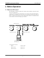
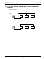
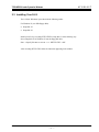
6 F 3 B 0 3 5 7 TOSLINE-S20/S20LP S20 Loader (for Windows) User's Manual Main Menu Contents May 1998 Toshiba Corporation UM-TLS20**-E006 TOSLINE-S20 Loader System for Windows 6 F 3 B 0 3 5 7 Contents 1. Introduction................................................................................................. 3 2. Before Operating........................................................................................ 4 3. 4. 2.1 What is S20 Loader? 2.2 TL-S20 (bus topology) Connection and TL-S20LP (loop topology) Connection 2.3 Installing Your S-LS 2.4 Operating Procedure 2.5 Difference Between the TL-S20 (bus topology) and the TL-S20LP (loop topology) Starting Up the Loader .............................................................................. 9 3.1 Connecting with a Station 3.2 Activating the Loader Operation................................................................................................... 11 4.1 Station Connection Diagram................................................................................ 11 4.1.1 Standard Size Window 4.1.2 Small Size Window 4.1.3 Transmission Error 4.1.4 Rearrangement 4.1.5 Scan Address List 4.2 Setting Information............................................................................................... 17 4.2.1 Scan Transmission Information 4.2.2 Station Control Information 4.2.3 SIF Setting Information 4.2.4 Saving All Setting Information 4.3 Data Access .......................................................................................................... 25 4.3.1 Access the Scan Area 4.4 RAS Information.................................................................................................... 29 4.4.1 Online Map 4.4.2 Scan Healthy Map 4.4.3 Loop Map 4.4.4 Station Status 4.4.5 Station Down Information 4.4.6 RAS Counter Information 1 TOSLINE-S20 Loader System for Windows 5. 6 F 3 B 0 3 5 7 4.5 Online/Standby Request ...................................................................................... 37 4.6 Test Request ......................................................................................................... 39 4.7 Communication Environment .............................................................................. 41 Termination............................................................................................... 44 2 TOSLINE-S20 Loader System for Windows 6 F 3 B 0 3 5 7 1. Introduction This User's Manual describes Toshiba's loader system for the data transmission equipment TOSLINE-S20/S20LP (S-LS for Windows). Toshiba has developed different S-LS versions for Windows 95, based on the S-LS for DOS. The two S-LS versions meet the TOSLINE-S20 for transmission in bus topology (hereafter called the "TL-S20") and the TOSLINE-S20LP for transmission in loop topology (hereafter called the "TLS20LP"). 3 TOSLINE-S20 Loader System for Windows 6 F 3 B 0 3 5 7 2. Before Operation 2.1 What is the S20 Loader? The S20 Loader on a personal computer (PC) monitors station conditions, reads/writes control data, and sets up parameters. As shown in the following figure, the S20 Loader on a PC connects with TL-S20 stations and TLS20LP stations via an RS-232C cable. The loader sets up and monitors the station with which the loader is connected (local station) and other stations being connected via transmission cable (remote stations). The loader can manage up to 64 stations. Transmission cable TL-S20 TL-S20 TL-S20 Request to local station Request to other stations RS-232C PC (IBM PC/AT compatible) OS : Windows 95 <Recommended environment> l CPU Pentium or higher l Main memory 24 MB or more l Hard disk space 20 MB or more 4 TL-S20 TOSLINE-S20 Loader System for Windows 6 F 3 B 0 3 5 7 2.2 TL-S20 (bus topology) Connection and TL-S20LP (loop topology) Connection <Bus topology connection> Loader TL-S20 TL-S20 TL-S20 TL-S20LP TL-S20LP TL-S20LP <Loop topology connection> Loader 5 TOSLINE-S20 Loader System for Windows 6 F 3 B 0 3 5 7 2.3 Installing Your S-LS The S-LS (for Windows) is provided with the following media: For Windows 95 (two 2HD floppy disks) • Setup disk 1/2 • Setup disk 2/2 Install your S-LS by executing SETUP.EXE in setup disk 1/2 in the following way. Insert setup disk 1/2 for Windows 95 into the floppy disk drive. Start → Specify file name to execute → A : ¥SETUP.EXE → OK After executing SETUP.EXE, follow the instruction appearing in the window. 6 TOSLINE-S20 Loader System for Windows 6 F 3 B 0 3 5 7 2.4 Operating Procedure This manual allows you to execute the S20 Loader in the following sequence. 3.1 Connecting with a Station l Connect your S20 Loader (on a PC) with an S20/S20LP transmission station via an RS-232C cable. 3.2 Activating the Loader program l Activate the Loader program. 4.1 Station Connection Diagram Selecting a station l Select specific functions from the station connection diagram. l Select a station. 4.2∼ Executing Commands l Set up parameters by commands to execute. 5 Termination l Terminate the S20 Loader program. 7 TOSLINE-S20 Loader System for Windows 6 F 3 B 0 3 5 7 2.5 Difference Between the TL-S20 (bus topology) and the TL-S20LP (loop topology) The following table lists the differences found between the TL-S20 (bus topology) and the TLS20LP (loop topology) in terms of functions. : Function Yes : Function No Function 1. Station Connection Diagram Detail Connection Diagram display Rearrangement Scan Transmission Address List 2. Setup Information Scan Transmission Information Station Control Information SIF Setup Information 3. Data Access Access to Scan Area Access to System Memory Area Access to SIF Memory Area Access to Dual-port Memory Area 4. RAS Information Online Map Scan Healthy Map Loop Map Station Status Station Down Information RAS Counter Information 5. Online/Standby Online Request Standby Request 6. Test Request Hardware Test Station Loop-back Test 7. Communication Environment Setup Communication Environment Setup 8 Bus topology Loop topology TOSLINE-S20 Loader System for Windows 6 F 3 B 0 3 5 7 3. Starting Up the Loader 3.1 Connecting with a Station The S20 Loader on a PC connects with a S20 transmission station via an RS-232C cable. This allows the loader to set up and monitor the transmission station and the other remote stations being connected via transmission cable. Use the following type of transmission cable to connect the 9-pin connector (male) on the PC with the 9-pin connector (female) on the S20 transmission station for LOADER (for the T series connection). l Transmission cable Product code TCJ905 ∗ CS Specification 9-pin D-Sub connector (both ends) (PC side : male, Station side : female) Length : 5 meters 3.2 Activating the Loader Use the RS-232C to connect your PC with a station before activating your S-LS Loader. The loader recognizes the station type (bus topology or loop topology) when activated; An error message will appear when the loader is not connected with the station. l Activating the Loader on Windows 95 The S-LS will be activated generally in the following sequence when the installation has been completed successfully. Start ↓ Program ↓ S-LS loader system for Windows 95 ↓ S-LS loader system for Windows 95 The above operation allows the loader program to get activated to the following communication environment contirmation window appears. 9 TOSLINE-S20 Loader System for Windows 6 F 3 B 0 3 5 7 l Window Image The communication environment confirmation window is designed for changing connection conditions with stations in future. Therefore, the window is wrrently unavailable. Press the “Continue” button. This operation allows the system configration diagram (base window) to appear. 10 TOSLINE-S20 Loader System for Windows 6 F 3 B 0 3 5 7 4. Operation 4.1 Station Connection Diagram 4.1.1 Standard Size Window l The Function Displays at a glance the types and statuses of the stations being connected. The window can transmit into any of the individual "TOSLINE-S20 Loader System" windows by selecting a station. l Window Image <Connection status> Common with bus topology and loop topology Station.ico Station.ico Online Standby <Transmission status> Station.ico Offline or not connected For loop topology only Normal Transmission Transmission loop 2 abnormal loop 1 abnormal 11 TOSLINE-S20 Loader System for Windows 6 F 3 B 0 3 5 7 l The Menu Individual "TOSLINE-S20 Loader System" windows can be displayed from the menu or the toolbar. Below are the details of the menu. Select an intended station in the Station Connection Diagram window for display and specify the window in the menu or the toolbar. [File] [Display Scan Address List].......................... Displays the Scan Address List window. [Display Station Down Information].............. Displays Down Information when the local station is downed. [Save Files All Station’s Information] ........... Saves the setup information of all stations in the file. [Exit] ............................................................. Terminates the application. [Menu] [Setting Information] ..................................... Displays the Setting Information window. [Data Access]................................................ Displays the Data Access window. [RAS Information] [Online Map] ......................................... Displays the Online Map window. [Scan Healthy Map]............................... Displays the Scan Healthy Map window. [Loop Map] ........................................... Displays the Loop Map window. [Station Status] ...................................... Displays the Station Status window. [Station Down Information] ................... Displays the Station Down Information. [RAS Counter Information] ................... Displays the RAS Counter Information [Online/Standby Request] ...................... Displays the Online/Standby Request window. [Test Request] ............................................... Displays the Test Request window. [Option] [Station Display Position] [Registration]......................................... Registers the display positions of the stations rearranged. [Display]................................................ Reflects the display positions of the registered stations in the window. [Normal] ................................................ Displays the stations rearranged in the ascending order of smaller display position numbers. [Communication Environment Setting].......... Displays the Communication Environment Setting window. [Window] [Display Small Size]...................................... Displays the Station Connection Diagram in small size. [Help] [Contents]...................................................... Displays the Help window. [Key Word Seareh] ....................................... Displays the Retrieve window in Help. [Version Information] .................................... Displays the information of the application version. l The Toolbar Function The toolbar has buttons for the functions frequently used. The following buttons are found from left to right. [Exit button] .................................................. Exits the application. [Setting Information button] .......................... Displays the Setup Information window. [Data Access button] ..................................... Displays the Data Access window. [RAS Information button].............................. Displays the RAS Information Menu window. [Online/Standby Request button] ................... Displays the Online/Standby Request window. [Test Request button] .................................... Displays the Test Request window. 12 TOSLINE-S20 Loader System for Windows 4.1.2 6 F 3 B 0 3 5 7 Small Size Window The small size window can display up to 64 stations in the 800 x 600 dots resolution. This window has the equivalent functions as the standard size window. l Window Image Different types of station icons appear in the window, depending on the station types. "Setting Information -- Scan Transmission Information" window will appear by double-clicking on a station icon. 13 TOSLINE-S20 Loader System for Windows 4.1.3 6 F 3 B 0 3 5 7 Transmission Error One of the following messages boxes will be displayed when an error occurs during the transmission between the TOSLINE-S20 Loader System and the TOSLINE-S20. Transmit Time Out Receive Time Out Start Code Error End Code Error BCC Error Connection Error Receive Data Length Error RX Text not matched TX Text Transmission is performed in 2 second cycle between the TOSLINE-S20 Loader System and the TOSLINE-S20. Clicking on the OK button resumes the 2 second cycle transmission when an error occurs. 14 TOSLINE-S20 Loader System for Windows 4.1.4 6 F 3 B 0 3 5 7 Rearrangement l The Function The display positions order of stations in the Station Connection Diagram window can be changed. However, this function is limited to the loop topology. l Window Image l How to Operate (1) Rearrange the station display positions by inserting the station selected into a desired display position. • Drag the station you want to rearrange while pressing the Shift key. ð The moving icon appears. ‚ While pressing the Shift key, move the dragging station to a position where you want to display, and then drop the icon. ð The station you dragged appears at the display position you dropped it. (2) Register the rearranged display position information. • From the menu, select "Option" - ""Station Display Position" - "Registration." ð The current station display position information is registered. Since this time, the Station Connection Diagram window displays the stations in the order of the display positions registered (3) Return the station display positions to the standard display positions. • From the menu, select "Option" - "Station Display Position" - "Normal." ð The stations appear in the ascending order of smaller display position numbers. 15 TOSLINE-S20 Loader System for Windows 4.1.5 6 F 3 B 0 3 5 7 Scan Address List l The Function Displays the scan address list of the stations being connected with the system. When an overlapped scan address is found in multiple stations, the address appear colored. This address appears only for the onlined or standby station. l Window Image l How to Operate (1) Display the Scan Address List window. • From the menu, select "Menu" - "Display Scan Address List." ð The Scan Address List window appears. (2) Read the information again. • From the menu, select "File" - "Read." ð The Scan Address display is updated. (3) Display the Scan Transmission Information Setting window. • Doubleclick the "No. : Kind" display area in the Scan Address List. ð The Scan Transmission Information Setting window of the corresponding station appears. 16 TOSLINE-S20 Loader System for Windows 6 F 3 B 0 3 5 7 4.2 Setting Information Displaying and setting the parameters of individual stations are available. However, these operations are available only when the station selected is in standby mode. The following information can be set. (1) Scan Transmission Information (2) Station Control Information (3) SIF Setting Information 17 TOSLINE-S20 Loader System for Windows 4.2.1 6 F 3 B 0 3 5 7 Scan Transmission Information l The Function The scan transmission information of the station being selected can be set or displayed. l Window Image l Station Type (1) (2) (3) (4) (5) (6) (7) (8) (9) (10) (11) (12) (13) (14) (15) <Bus topology> T4 : T4 station T3 : T3 station T2 : T2 station HTI : Handy terminal interface PLC-5 : PLC-5 PC/AT : PC/AT bus SIF : Serial interface MDM05 : MDM05 PC98 : PC9801 SG : MCR22 PCS : PCS4000/6000/7000 VME : VME bus CYCLO : TOSCYCLO-u/H850 U/S : TOSVERT-u/S250 VF : TOSVERT-VF <Loop topology> (1) G200H : G200H station (2) MCR25 : MCR station (3) PTLS9 : PCS station (4) SBL22 : Signal transmission device station (5) T3H : T3H station (6) TS25 : Modem interface For the station undefined, the station type code is displayed 18 TOSLINE-S20 Loader System for Windows 6 F 3 B 0 3 5 7 l Possible Setup Items (1) Transmission top address 1 (TL-S20 : 0∼1023) (TL-S20LP : 0∼4095) (2) Number of transmission words 1 (0∼1024) (3) Transmission top address 2 (TL-S20 : 0∼1023) (TL-S20LP : 0∼4095) (4) Number of transmission words 2 (0∼1024) l How to Operate (1) Setting values • Enter the values of transmission top address 1, number of transmission words 1, transmission top address 2, and number of transmission words 2.(Enter values directly, or select from the combo box or using the spin button) ‚ Click on the "OK" or "Update" button. ð The data you set is transmitted to the corresponding station. (2) Canceling the values after setup • Click on the "Cancel" button. ð The data you set becomes invalid and the Setting Information window disappears. (3) Selecting a station • Select a station number from the combo box or using the spin button. ð The window is changed over to the selected station information. (4) Saving in the file (one corresponding station) • Select "Save As " from the menu or click on the "Save As " button in the upper-right corner of the window. ð A dialog box appears for specifying a file name to be saved. ‚ Set up the path of the file name to be saved in the dialog box. ð The setup information file of the corresponding station is output to the path specified. (5) Reading from the file (one corresponding station) • Select "Read File" from the menu, or click on the "Read File" button in the upper-right corner of the window. ð A dialog box appears for specifying a file name to be read. ‚ Set up the path of the file name to be red in the dialog box. ð From the path specified, the setup information of the corresponding station is read and displayed. 19 TOSLINE-S20 Loader System for Windows 6 F 3 B 0 3 5 7 4.2.2 Station Control Information l The Function The station control information of the station being selected can be set and displayed. l Window Image l Possible Setup Items (1) Inhibits/allows scan transmission (2) Number of scan access words (1W/2W) (3) Inhibits/allows message transmission (4) Target cycle time unit: msec 3.07 4.10 5.12 6.14 7.17 8.19 9.22 10.2 11.3 12.3 13.3 14.3 15.4 16.3 20.5 24.6 28.7 32.8 36.9 41.0 45.1 49.2 53.2 57.3 61.4 (5) Standby startup (yes/no) 20 TOSLINE-S20 Loader System for Windows 6 F 3 B 0 3 5 7 l How to Operate (1) Setting inhibit/allow scan transmission, number of scan access words, inhibit/allow message transmission, and standby startup (check box) • Select either of the values in the window ‚ Click on the "OK" or "Update" button. ð The data you set is transmitted to the corresponding station. (2) Setting a target cycle time • From the combo box, select the target cycle time you want to set. ‚ Click on the "OK" or "Update" button. ð The data you set is transmitted to the corresponding station. (3) Canceling the values after setup • Click on the "Cancel" button. ð The data you set becomes invalid and the setup information window disappears. (4) Selecting a station • Select a station number from the combo box or by using the spin button. ð The widow is changed over to the selected station information. (5) Saving in a file (one corresponding station) • Select "Save As ..." from the menu, or click on the "Save As .." button in the upper-right corner of the window. ð A dialog box appears for specifying a file name to be saved. ‚ Set up the path of the saving file name in the dialog box. ð The setup information file of the corresponding station is output to the path specified. (6) Reading from the file (one corresponding station) • Select "Read File" from the menu or click on the "Read File" in the upper-right corner of the window. ð A dialog box appears for specifying a file name to be read. ‚ In the dialog box, set up the path of the file name to be read. ð From the path specified, the setup information of the corresponding station is read and displayed. 21 TOSLINE-S20 Loader System for Windows 4.2.3 6 F 3 B 0 3 5 7 SIF Setting Information l The Function The SIF setting information of the station selected can be set and displayed. This function is available for the TL-S20 (bus topology) only. l Window Image l Possible Setup Items Set the information by ports (port 1/port 2) (1) Baud rate (300, 600, 1200, 2400, 4800, 9600, 19200) BPS (2) Data length (7, 8) bits (3) Stop bits (1, 2) bit (4) Parity bit (none, odd parity, even parity) (5) Yes/No of flow control (6) Transmission type (message transmission, free-run/broadcast) (7) Virtual Circuit target station (none, 1 to 64) (8) Virtual Circuit target port (none, 1, 2) (9) Multicast address (none, 0 to 9) 22 TOSLINE-S20 Loader System for Windows 6 F 3 B 0 3 5 7 l How to Operate (1) Selecting a port to be set up • Select a port (port 1/port 2) you want to set up on the window. ð The setup information for the port selected appears. (2) Setting up individual items information • Change individual items information on the window. ‚ Click on the "OK" or "Update" button. ð The data you set is transmitted to the corresponding station. (3) Canceling the values after setup • Click on the "Cancel" button. ð The data you set becomes invalid, and the Setting Information window disappears. (4) Selecting a station • Select a station number from the combo box or using the spin button. ð The information of the station selected appears. (5) Save in a file (one corresponding station) • Select "Save As ..." from the menu or click on the "Save As .." button in upper-right corner of the window. ð A dialog box appears for specifying a file name to be saved. ‚ Set up the path of the file name to be saved in the dialog box. ð The setup information file of the corresponding station is output to the path specified. (6) Reading from the file (one corresponding station) • Select "Reading File" from the menu, or click on the "Read File" button in upper-right corner of the window. ð A dialog box appears for specifying a file name to be read. ‚ Setup the path of the file name to be read in the dialog box. ð The setup information of the corresponding station is read from the file specified for display. 23 TOSLINE-S20 Loader System for Windows 4.2.4 6 F 3 B 0 3 5 7 Saving All Station’s Information l The Function Currently, all of the setting information of the individual stations being connected with the system can be saved. (1) Scan transmission information (2) Station control information (3) SIF unit setup information l Window Image l How to Operate • From the menu, select "File" - "Save Files All Stations’s Information" in the Station Connection Diagram. ð A dialog box appears for specifying a saving directory. ‚ Set a saving directory name in the dialog box. ð The Setting information file of the individual stations is output onto the directory specified. 24 TOSLINE-S20 Loader System for Windows 6 F 3 B 0 3 5 7 4.3 Data Access Reading and writing are available for the scan memory of the stations being connected. Specify a station number and the top address to access the scan area. The data display format in decimal or hexadecimal notation can be selected. The data at the same address can be read out periodically (2 second cycle) for display by checking "Cyclic Data Read." Scan data can be read and written to/from a file. l Window Image 25 TOSLINE-S20 Loader System for Windows 4.3.1 6 F 3 B 0 3 5 7 Access to Scan Area l The Function The scan area of the stations being selected can be set and displayed. l Window Image l How to Operate (1) Displaying values • Set the station number, top address, number of words to be read in the data access menu. ‚ Click on the "Execute" button ð The data of the station selected appears. (2) Continuous data read • Check the check box for "Cyclic Data Read" in the window, and click on the "Execute" button. ð The data at the same address is read periodically (2 seconds cycle) for display. (3) Changing the data display format • Click on the "Decimal" or "Hexadecimal" button in the window. ð The data display format is changed over to the one specified (display on the button is in current format). 26 TOSLINE-S20 Loader System for Windows 6 F 3 B 0 3 5 7 (4) Setting values (during "Cyclic Data Read" no setup operation is available) • Click on the data you want to set. ‚ Change the data you want to set. ƒ Click on the "Data Write" button. ð The data changed is sent to the corresponding station. (5) Saving data in a file • While the data is being displayed in the window, select "File Operation" – "Save As ... " from the menu, or click on the "Save As ... " button in the window. ð A dialog box appears for specifying a file name to be saved. ‚ Specifying a file name in the dialog. ð The data being displayed is output onto the file name specified. (6) Reading the data in a file • Select "File Operation" – "Read from File" from the menu. Or click on the "Read File" button in the window. ð A dialog box appears for specifying a file name to be read. ‚ Specifying a file name to read in the dialog. ð Data is read from the file specified for display. 27 TOSLINE-S20 Loader System for Windows 6 F 3 B 0 3 5 7 l Window Image (Data display status) l Window Image (Dialog for specifying a file name) 28 TOSLINE-S20 Loader System for Windows 6 F 3 B 0 3 5 7 4.4 RAS Information The RAS information generated in station is read. When the RAS information on the toolbar in the Station Connection Diagram window is clicked on, the RAS Information menu appears. By selecting a window you want to display from the RAS Information menu, the window appears. The RAS Information has the following six types of windows. (1) Online Map Displays the connection status of individual stations. (2) Scan Healthy Map(not found in the TL-S20LP (loop topology)) Displays execution status of scan transmission by the word in the scan area. (3) Loop Map (not found in the TL-S20 (bus topology)) Displays the loop status of individual stations. (4) Station Status Displays the station status of any arbitrary stations. (5) Station Down Information Reads the cause of the down from the station downed for display. (6)RAS Counter Information Displays the RAS counter information of any arbitrary stations. 29 TOSLINE-S20 Loader System for Windows 4.4.1 6 F 3 B 0 3 5 7 Online Map l The Function Displays the connection status of a station, which is read in 3-second interval from the station. l Window Image (Blue) : Online mode. (Red) : Standby mode. l How to Operate • Select Online Map from the RAS Information menu. ð The Online Map window appears. 30 TOSLINE-S20 Loader System for Windows 4.4.2 6 F 3 B 0 3 5 7 Scan Healthy Map l The Function Displays the execution status of scan transmission by the word in the scan area. The status is read in 3 seconds cycle for display from the station. This function is not found in the TL-S20LP (loop topology). l Window Image (Blue) : Scan data is normally updated. (Red) : Scan data is not updated. l How to Operate • Select Scan Healthy Map from the RAS Information menu. ð The Scan Healthy Map window appears. 31 TOSLINE-S20 Loader System for Windows 4.4.3 6 F 3 B 0 3 5 7 Loop Map l The Function The loop statuses of individual stations are displayed. This function is not found in the TL-S20 (bus topology). l Window Image l Status Types No. Loop status mode Station type Display mark 1 Cut off Terminal station Yellow 2 Trough Terminal station Light blue 3 End1 Terminal station Purple 4 End2 Terminal station Green 5 Trough General station Light blue 6 End1 General station Yellow 7 End2 General station Purple End1: Loop 1 side transmission disabled / Loop 2 side reception disabled. End2: Loop 2 side transmission disabled / Loop 1 side reception disabled. l How to Operate • Select Loop Map from the RAS information menu. ð The Loop Map window appears. 32 Color TOSLINE-S20 Loader System for Windows 4.4.4 6 F 3 B 0 3 5 7 Station Status l The Function Reads and displays the station status of the station specified. l Window Image l Display Items (1) Online status (online, offline, standby) (2) Master station / Slave station mode (3) Scan transmission inhibit/allow (inhibit, allow) (4) Test (execute, not execute) (5) External device 1 (normal, abnormal/ not connected) (6) External device 2 (normal, abnormal / not connected) The loop topology version has the following additional items: (5) RCV1: TX2 status (allow, inhibit) (6) RCV2: TX1 status (allow, inhibit) (7) Loop status (Cut-off, Through, End1/2) 33 TOSLINE-S20 Loader System for Windows 4.4.5 6 F 3 B 0 3 5 7 Station Down Information l The Function Reads and displays the down cause of the station being downed. This function is used by directly connecting the S20 loader with the station being downed. Another station in the network cannot read the status information of the station being downed. l Window Image l Down Messages (1) 10H : Watch Dog Timer Error (2) 20H : Memory Bus Error (3) 30H : SIF malfunction (4) 40H : Jabber Timeout (5) 60H : Hardware Error (6) 67H : SIF Initializing Error (7) 77H : Receive Buffer Overflow (8) For the unknown code: error codes and "Undefined Down Code" The following message box appears when the station specified is normal. 34 TOSLINE-S20 Loader System for Windows 4.4.6 6 F 3 B 0 3 5 7 RAS Counter Information l The Function Displays the RAS Counter Information of the corresponding station. l Window Image l Display Items Network Information (clear allowed) Station information (clear inhibited) Entering In The Network Station type Getting Out The Network ROM Rev. Network Error Date of creation Block check code (BCC_L, BCC_H) 35 TOSLINE-S20 Loader System for Windows 6 F 3 B 0 3 5 7 l How to Operate (1) Displaying the RAS Counter Information window • Select RAS Counter Information from the RAS Information menu. ð The RAS Counter Information window appears. (2) Cyclic reading information • Check "Cyclic Reading" in the check box in the window. ð RAS Counter Information is read cyclically (2 seconds) for display. (3) Clearing information in the RAS counter • Select "Operate" - "Clear Counter" from the menu. ð A message box appears to confirm the execution of clearing the information. ‚ Click on "OK" in the Confirm message box. ð RAS Information Counter is cleared. 36 TOSLINE-S20 Loader System for Windows 6 F 3 B 0 3 5 7 4.5 Online/Standby Request 4.5.1 Online/Standby Request l The Function An "Online Request" or "Standby Request" is issued for the station selected. This request is always available for the local station (where the S20 loader is connected). For the other stations, this function is available when the local station is onlined or in standby. l Window Image l Operation (1) Online/Standby request to a station selected • Select the station number. ‚ Select the request type. ƒ Click on "Execute" button ð The request selected is issued for the station selected. 37 TOSLINE-S20 Loader System for Windows 6 F 3 B 0 3 5 7 (2) Online/Standby request for multiple stations • Select "Option" – "Operate Multiple Stations" from the menu. ð A window for operating multiple stations appears. ‚ Select the stations you want to request. ð The stations selected appear reversed. ƒ Select a request type. „ Click on the "Execute" button ð The request selected is issued for the multiple stations selected. 38 TOSLINE-S20 Loader System for Windows 6 F 3 B 0 3 5 7 4.6 Test Request l The Function Hardware test: Checks the ROM area, setup switch, and the station for the appropriateness (for the local station only). Hardware test is available in standby mode only. Note:Separate the station from the other stations. Otherwise, some of them may get malfunctioned. Station loop back test: Transmits data between the local station and the station specified. l Window Image l Operation (1) Hardware test • Select the station you want to test. ‚ Select a request type for hardware test. ƒ Click on the "Execute" button. ð The following Confirm window appears. „ Click on the "OK" button. ð A hardware test is executed. 39 TOSLINE-S20 Loader System for Windows 6 F 3 B 0 3 5 7 (2) Station loop back test • Select a request type for station loop back test. ‚ Select a station you want to test. ƒ Enter the number of the test times. „ Click on the "Execute" button. ð A Confirm window will appear. … Click on the "OK" button. ð A station return test is executed. † Click on the "Break" button when suspension is necessary. ð A station return test is breaked. 40 TOSLINE-S20 Loader System for Windows 6 F 3 B 0 3 5 7 4.7 Communication Environment l The Function Sets up the communication environment for the "TOSLINE-S20 Loader System." Except for setting up the "communication port" in the following (1), special key operation is required. While pressing the Ctrl key, click on the icon at the upper-left in the Communication Environment Setup window for unlocking. l Window Image (environment setup) l Setup Items (1) Communication port ( COMM 1 to COMM 16 ) (2) Baud rate ( 1200, 2400, 4800, 9600, 19200 ) BPS (3) Parity ( none, odd parity, even parity ) (4) Data length ( 7, 8 ) bits (5) Stop bit ( 1, 1.5, 2 ) bits The underline data indicates the default setting. 41 TOSLINE-S20 Loader System for Windows 6 F 3 B 0 3 5 7 l Window Image (how to communicate) l Setup Items (1) Receive buffer size ( 1024 ) (2) Character string size to be read ( 256 ) (3) Transmit buffer size ( 512 ) (4) Replacement Character on parity error ( ? ) (5) Whether Null is transferred to the receive buffer ( True, False ) The underlined data indicates the default setting. 42 TOSLINE-S20 Loader System for Windows 6 F 3 B 0 3 5 7 l Window Image (detailed setup) l Setup Items (1) Whether DTR line is set to active or not ( True, False ) (2) Whether RTS line is set to active or not ( True, False ) (3) Setting handshaking ( XON/XOFF, CTS/RTS ) (4) Occurrence interval of reception OnCom event ( 1 to 256 ) per character (5) Occurrence interval of transmission OnCom event ( 1 to 256 ) per character The underlined data indicates the default setting. 43 TOSLINE-S20 Loader System for Windows 6 F 3 B 0 3 5 7 5. Termination Terminate the S20 Loader from the menu or the toolbar. l Menu [File] [Exit] .................................................. Exits the application. l Toolbar [Exit button] (button at left end)......... Exits the application. 44 Toshiba Corporation FCF50016B