1
USOO5655093A
Umted States Patent [19]
[11] Patent Number:
Frid-Nielsen
[45] Date of Patent:
[54]
INTELLIGENT SCREEN CURSOR
5,235,679
[75] Inventor: Lars Frid-Nielsen, Santa Cruz, Calif.
_
Aug. 5, 1997
8/1993 Yoshizawa et al. .............. .. 395/161 X
OTHER PUBLICATIONS
_
Mastering WordPerfect 5.1 X 5.2 for Windows (Trademark
[73] Asslgnw Borlmld llytema?oml, hm 599m
Valley, Cahf-
of Sybex 1110.), 1992, pp. 6-8, 69-70, 646-649, 659 x
665-666.
Wordperfect 5.1 for Windows by Example (Trademark of
Tony Webster & Associates), 1992, pp. 1, 3, 9, 381, 385 &
[21] Appl. N0.: 751,457
.
5,655,093
_
551-554.
[22] F?ed'
Nov‘ 18’ 1996
Matthies, Kurt W.G., Balloon Help Takes Off, MacUser,
Dec. 1991, pp. 241-248.
Related US. Application Data
Primary Examiner—Phu K. Nguyen
[63]
[51]
Continuation of Ser. No. 847,504, Mar. 6, 1992, abandoned.
Int. Cl.6 ...................................................... .. G06F 3/00
Assistant Examiner_clj?= N, V0
A?vmey’ 48'6"’, 0’ I'm/"John A- SW
[52]
US. Cl. .............. ..
[57]
[58]
Field of Search ................................... .. 395/326, 334,
[56]
395/336 331 337; 345/156. 167
'
References Cited
395/326; 395/334
ABSTRACT
_
_
_
A system for asslstmg a user of a computer system 1n
entering valid information includes a computer having a
processor and a memory, a display device for illustrating
screen objects, a screen cursor for indicating a location on
U-S- PATENT DOCUMENTS
the display device, an input device for positioning the screen
4,622,013
11/1986 Cerchio ............................. .. 434/118 X
Cursor» and Screen i?fomlation for indicating user operations
4,789,962
12/1988
Berry . . . . . .
. . . . .. 395/155 X
available Wlth thc input device
4,964,077
10/1990
Eisen . . . . . . .
. . . . . ..
5,123,087
364/4191
6/1992 Newell .............................. .. 395/155 X
(-280
NONE
(MOVEMENT ONLY)
I
r281
1 Claim, 14 Drawing Sheets
r282
LEFT
SGL CLICK
r283
LEFT SGL
AND DBL
CLICKS
I.‘
v/—2t34
LEFT SGL
AND DBL
LEFT SGL
AND DBL
RIGHT
SGL CLICK
RIGHT SGL
AND DBL
CLICKS
CLICKS;
CLICKS;
I:
LEFT 8G.
AND DBL
LEFT
SGL CLICK
LEFT
DBL CLICK
MODE: DRAW,
LEH' SGL
CLICKS
+ DRAG
+ DRAG;
AND DBL
+ DRAG;
RIGHT
RIGHT
SGL CLICK
SGL CLICK
CUCKS ,
+ DRAG;
RIG
US. Patent
Aug. 5, 1997
Sheet 1 of 14
5,655,093
l°_°_
f.
104
KEYBOARD
(_
POINTING
DEVICE
r
DISPLAY
DEVICE
r’
102
r.
MAIN
MEMORY
MASS
sTORAGE
r
I/O
CONTROLLER
PRINTING
101
DEVICE
r
CENTRAL
PRocEssOR
FIG. 1A
150 x
153
152
r
‘r’
r15‘
APPLICATION %
SOFTWARE 5
OPERATING
I‘!
SYSTEM
2
.___.
mm
FIG. 1B
US. Patent
Aug. 5, 1997
Sheet 2 0f 14
5,655,093
m3
1
mmm
an.
l x+
8.8.
mmm
U.S. Patent
Aug. 5, 1997
com
:N
6w.25.29:8
“x2(m E@5;;25e22“86
H.2m6[v2?
Sheet 4 of 14
5,655,093
US. Patent
Aug. 5, 1997
82.53m%
mmw
K(
258m“i:n.E8a-H“umd
NvN
a.v...
Sheet 5 of 14
5,655,093
U.S. Patent
Aug. 5, 1997
Sheet 6 0f 14
5,655,093
ocm
6Emm
..
US. Patent
Aug. 5, 1997
Q
Elle Edit Icx! ?rawlng Eminence:
Sheet 7 0f 14
.‘lamulc ?pplu mum
/' Q
241
M
FIG. 3A
FIG. 38
FIG. 30
FIG. 30
FIG. 3E
5,655,093
US. Patent
Aug. 5, 1997
Sheet 8 0f 14
5,655,093
llc Elli Iexl Qmdng Entrance:
{- 241
FIG. 3F
DE]
1:]
DE]
CID
E]
[If]
US. Patent
Aug. 5, 1997
5 n W Mr M.
le
Sheet 9 of 14
5,655,093
W u a. u
Edi! Icxl DIM“. Ele'ercnccl
FIG. 4A
241
241
FIG. 4B
FIG. 40
275d
241
FIG. 40
‘\
2750
241
FIG. 4E
US. Patent
Aug. 5, 1997
Sheet 11 of 14
5,655,093
m
a
w
k
E540m .Enaz< 9630
9»6E
m:5
3N8N\
\\
anE56mEm:
5:0+
E59wanEm: v563 has
TimEEx
US. Patent
Aug. 5, 1997
Sheet 12 0f 14
5,655,093
FIG.5B
US. Patent
Aug. 5, 1997
Sheet 13 of 14
Sampte Appm 8mm
I: Ed" Ind Drawing Bckrcnocs
am Lm Bm
T0 SELECT OBJECT
FIG. 6A
5 m W W m. pliuliuu
l6 Elm Ind Drawing Eminence:
FIG. 6B
5,655,093
US. Patent
Aug. 5, 1997
log
I
Sheet 14 0f 14
START
)
w
r 701
DETERMINE IF MOUSE PRESENT
(SM_MOUSEPRESENT)
DETERMINE MOUSE SIGNALS
WHICH ARE VALID
"
r 703
DETERMINE BITMAP ICON
WHICH MATCHES AVAILABLE
VALID INPUT SIGNALS
v
SET MOUSE ICON TO
DETERMINED BITMAP
(SETCURSOR)
NO
FIG. 7
f- 704
5,655,093
5,655,093
1
2
INTELLIGENT SCREEN CURSOR
process one user-typed command at a time. In an effort to
keep the number of keystrokes required for a command to a
manageable level, these command-line interfaces tended to
employ short commands; however, these commands were
often cryptic as well. Thus while VDTs provided increased
?exibility, these “command-line” interfaces were still far
This is a File Wrapper Continuation Patent application of
application Ser. No. 07/847504, ?led Mar. 6, 1992, now
abandoned.
A portion of the disclosure of this patent document
contains material which is subject to copyright protection.
from intuitive for the average user.
The copyright owner has no objection to the facsimile
With increasingly widespread availability of powerful
reproduction by anyone of the patent document or the patent
microprocessors, graphical user interfaces (GUIs, pro
disclosure as it appears in the Patent and Trademark O?ice 10 nounces “gooeys”) have become feasible. A GUI is a type of
display format that enables a user to operate a computer by
patent ?le or records, but otherwise reserves all copyright
rights whatsoever.
pointing to pictorial representations, such as “icons”
(bitmaps) and “pull down” menus, displayed on a screen
BACKGROUND OF THE INVENTION
The present invention relates generally to computer sys
tems and, more particularly, to systems and techniques for
receiving information from and conveying information to a
device. Choices are generally selected by the user with a
15
keyboard and/or pointing device; the latter including such
well-known devices as a mouse, track ball, digitizing tablet,
and light pen, or the like. Thus, the need for the user to
memorize special commands has been lessened by the
ability to operate a computer by selecting screen objects.
user of a computer system.
With the advent of the personal computer. the use of
computer systems is becoming increasingly prevalent in
Well-known GUIs include Apple’s Macintosh (Mac)
interface, Microsoft’s Windows, IBM’s OS/2 Presentation
everyday life. In the past, computers were often housed in
highly restricted areas. with access limited to a few com
Manager, Sun Microsystem’s Open Look, and Open Soft
puter scientists and programmers. Today, however, comput
ware Foundation’s Motif. Employing one or more windows,
a menu bar, and a screen pointer, each of these systems can
ers can be seen on the desktops of most business profes
sionals. Running software applications such as word
processors and spreadsheets, for example, even the average
business professional can realize substantial productivity
gains. Besides the business environment, computers can also
25
be readily distinguished from almost any non-GUI system.
The screen cursor or pointer, typically displayed as a
small arrow icon (bitmap), allows the user to select indi
vidual points on the screen. In operation, the screen cursor
be found in wide use both at home and at school.
Also in contrast to the past, the average computer user of
moves to a desired screen location in response to movements
today is usually not a computer scientist. Instead, he or she
will typically have little or no formal training in the com
movement, most pointing devices include one or more
puter sciences or even in the basic use of a personal
input or “user events.” For example, a user may select a
computer. Nevertheless, these untrained workers often must
be pro?cient in the use of computers in order to compete
effectively in the job market. An applicant for a legal
of a pointing device (e.g., mouse) by the user. Besides
switches or “mouse buttons” for specifying additional user
35
screen point by “clicking” (depressing and releasing) a
mouse button once while the cursor is positioned at the
desired point. By double-clicking (two mouse clicks in rapid
secretary position today, for example, is expected to be
succession) a user may select an item and start an action. By
pro?cient in the use of wordprocessing software, such as
WordPerfectTM. As a result, there have been much interest in
providing computers which are easier to use.
To increase ease of use, designers of computer systems
“dragging” (continually depressing a mouse button) the user
may move objects on the screen or select groups of objects.
Thus, objects can be picked up, moved, and directly manipu
lated with a versatility that is not possible with a keyboard
alone. Moveover, pointing is a very natural, human action
have labored for decades to create architectures which are
intuitive. Most of this effort has been centered around the
user interface or UI-the means by which a user commu
nicates (i.e., supplies input and receives output) with a
45
The menu bar runs across the top of the screen and serves
computer. Not surprisingly, the quality of a user interface
depends to an extent on the technology in the underlying
hardware.
Early advances in user interface design came in the form
to group or categorize commands available to the user.
Clicking on an item on the menu bar typically causes a
“pull-down” menu to appear. This second or “submenu” also
includes a number of items, each of which is associated with
a desired action, including the display of even more menus.
To select a desired action, the user usually clicks the
of “interactive” computer systems. Unlike “batchprocess
ing” systems, these computers allowed users to interact in
real-time, often printing the desired results moments after
the user had keyed in an appropriate command. Employing
teletype ('ITY) terminals, however, these early command
corresponding menu item with the screen or mouse pointer.
For some menu items, particularly those which may be
55
line systems were interactive only to the extent of receiving
or printing one line of text at a time.
As TI'Y interfaces gave way to video display terminals
(V DTs), it became possible for a user to input and receive
information anywhere on a screen. Typically employing
special keystrokes, these character-based VDTs allowed a
terms were still rather limited in their ability to receive user
input, however. A typical system, for example, could only
nested in several layers deep, a keyboard equivalent or “hot
key” may be available but. Unfortunately, these must also be
memorized by the user.
A window is a rectangle displayed on the screen that
allows a user to work within a program. In typical operation,
the user may move the window about on the screen, change
its size or shape, enlarge it to ?ll the screen, close it entirely,
user to move a cursor across the screen. Thus, a user could
“go back” (reposition the cursor) and correct mistakes
and/or otherwise update information.
Exempli?ed by Microsoft’s DOS A> prompt, these sys
which, unlike a keyboard, does not require any special
training to master.
or change how much of its contents are displayed. To aid the
user in the manipulation of its contents, a window will
typically include a number of user interface components,
65
such as buttons, menus, sliders, and the like. Outside the
window, the screen can display other screen objects, such as
other windows, disk drive icons, or even a trash can icon.
5,655,093
4
3
BRIEF/DESCRIPTION OF THE DRAWINGS
Another advantage attendant to a GUI environment is
consistency of operation between application software. For
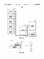
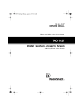
FIG. 1A is a block diagram of a computer system in which
example. a task common to more than one application (e.g.,
the present invention may be embodied.
saving a data ?le) is generally performed in the same manner
regardless of the particular application (e.g., spreadsheet,
FIG. 1B a block diagram of a software system of the
wordprocessor, and the like) currently operating. To foster
this consistency, most GUI vendors publish style guides
setting forth interface guidelines for application developers.
IBM’s System Application Architecture, Common-User
Access: Advanced Interface Design Guide (SC26-4582-O)
present invention, which may include operating system,
application software, and user interface components.
including the operation of a screen (mouse) cursor or
and Microsoft’s Windows style guides are two such
pointer.
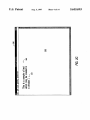
FIG. 2A bitmap screen shots illustrating the basic archi
tecture and functionality of a graphical user interface,
examples.
FIG. 2B is a collection of screen cursor icons. which may
Despite etforts to present a consistent interface, however,
most application software still requires complex user
serve to indicate different modes (e.g., “drawing” mode) of
operation.
actions. such as triple-clicking or dragging a mouse device
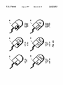
FIGS. ZC-E are bitmap screen shots illustrating the use of
different screen cursors to indicate mode of operation.
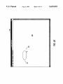
FIGS. 3A-E illustrate the operation of a screen cursor
while a key is held down. Thus, there typically exists a
plethora of ways to do almost anything in a graphical
interface. such as the Mac. While this increases the ?exibil
ity of a system. it also adds to the complexity of the interface
that the user must master. And this problem is by no means
limited just to novice users. Experienced computer users are '
20
which does not provide immediate feedback of the actual
input options available to the user.
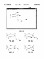
PIGS. 3F-J illustrate the operation of a screen cursor
which. unlike the cursor of FIGS. 3A-E, indicates the
availability of an additional mode; however. the cursor still
than novice users.
does
not provide immediate feedback of the actual input
The problem of interface complexity is even worse
between GUIs from di?erent vendors. In that case, there is 25 options available to the user.
FIGS. 4A-E illustrate an intelligent screen cursor of the
usually no common style guide to which the multi-platform
present invention. which allows the user to immediately
application developer can turn. Moreover, competing GUIs
determine valid options available for an input device.
will often be purposely inconsistent. presumably for mar
keting and/or legal reasons. All told, the user is still required
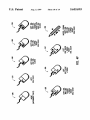
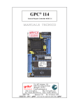
FIGS. 4F-G are a collection of icons for the intelligent
30 screen cursor of the present invention, each of which serves
to memorize special commands.
The present invention recognizes that it is highly desirable
to indicate valid options available for an input device;
reluctant to read user manuals and, hence, often fair no better
to provide computers with system and application software
different modes (e.g., “drawing” mode) of operation may be
which is highly intuitive to users. including those who are
indicated as well.
untrained in the use of the software. What is needed is a
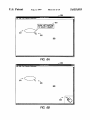
FIGS. SA-B are partial bitmap screen shots illustrating
system and interface methods which require little or no 35 the advantages of the intelligent screen cursor during inter
knowledge of speci?c commands by the user. More
action with a window scroll bar.
particularly, the system should automatically and explicitly
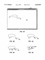
FIG. 6A is a bitmap screen shot illustrating an alternative
indicate to the user the appropriate action he or she may take.
embodiment of the present invention, where the intelligent
The present invention ful?lls this and other needs.
SUIVIMARY OF THE INVENTION
A system of the present invention for assisting the user in
entering valid information includes a computer having a
processor and a memory, a display device for illustrating
screen cursor is augmented with textual screen infonnati'on.
FIG. 6B is a bitmap screen shot illustrating a lesser
preferred embodiment of the present invention, where user
feedback is provided by graphic and/or textual information
or other indicia displayed at a location remote from the
screen objects. a screen cursor for indicating a location on 45 actual screen cursor.
the display device, an input device for positioning the screen
cursor, and displayed screen information for indicating user
operations available with the input device. In a preferred
embodiment, the system includes an intelligent screen cur
sor providing both screen location information as well as
information about which user input(s), if any, are valid in a
given context of the system.
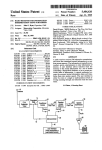
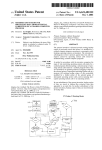
FIG. 7 is a ?owchart of a method of the present invention
for implementing an intelligent screen cursor.
DETAILED DESCRIPTION OF A PREFERRED
ENIBODIMENT
The invention may be embodied on a computer system
such as the system 100 of FIG. 1A, which comprises a
central processor 101, a main memory 102, an input/output
A method of the present invention for assisting a user of
controller 103, a keyboard 104, a pointing device 105 (e.g.,
a computer system having an input device includes deter
mining valid user signals which are available for the input 55 mouse, track ball, pen device, or the like), a display device
106, and a mass storage 107 (e.g., hard disk). Additional
device in the current context of the system, displaying screen
input/output devices, such as a printing device 108, may be
information indicating operation(s) of the input device
included in the system 100 as desired As shown, the various
which correspond to the determined valid user signals, and
components of the system 100 communicate through a
continually updating the screen information for different
screen locations or contexts of the computer system. In a
system bus 110 or similar architecture.
preferred method of the present invention, the valid signals
Illustrated in FIG. 1B, a computer software system 150 is
or user inputs which may be entered with a pointing device
provided for programming the operation of the computer
are indicated to the user by a screen cursor bitmap, which
system 100. Software system 150, which is stored in system
illustrates how the signals are generated. For a two-button
memory 102 and on disk memory 107, includes an kernel or
mouse device, for example. the bitmap cursor may display 65 operating system 151 and a shell or interface 153. One or
a mouse device icon showing which button(s) should be
depressed.
more application programs, such as application software
152, may be “loaded” (i.e., transferred from storage 107 into
5 ,655,093
5
6
memory 102) for execution by the system 100. Under the
command of software 151 and/or application software 152,
spot” (e.g., the tip of the arrow) for indicating an exact
position. Since the most popular pointing device employed
the system 100 receives user commands and data through
user interface 153. The interface 153 also serves to display
is a mouse device, the screen cursor 225 is often referred to
as a “mouse cursor.” Single-button, double-button, and
triple-button mouse devices which may serve to generate
signals for the cursor 225 are available from a variety of
results, whereupon the user may supply additional inputs or
terminate the session.
In a preferred embodiment. the system 100 is an IBM
vendors including Apple Computers of Cupertino, Calif,
compatible personal computer, available from a variety of
vendors (including IBM of Armonk, NY.) Operating sys
Microsoft Corporation of Redmond, Wash., and Logitech
Corporation of Fremont, Calif.
term 151 is MS-DOS and interface 153 is Microsoft
Windows, both of which are available from Microsoft
standard or stock cursors 230-239 for use by application
As shown in FIG. 2B, Microsoft Windows includes
Corporation of Redmond. Wash. Application software 152
be implemented in other platforms, including Macintosh,
programs. As shown in FIGS. 2C—E, these different cursor
bitmaps are employed to indicate different modes of opera
tion. In FIG. 2C, for example. the user has entered a text
object 240 in the client area 220 of the window 200. In this
example, the mouse pointer is displayed as the I-beam cursor
Unix. and the like. While the present invention is best
bitmap 231, for indicating the current insertion point for
implemented in those systems employing computer
entering text into the client area 220. Thus, the cursor 231
indicates a screen position and a system mode (text entry).
can be any one of a variety of software applications,
including word processing. database, spreadsheet. CAD
applications. and the like. Alternatively, the system 100 may
graphics. those skilled in the art will also appreciate that the
present invention may be employed in certain character
15
20
based systems, as well.
In a similar manner, as shown in FIG. 2D, the screen
cursor may be displayed as a crosshair bitmap 233. In this
example, the crosshair indicates a screen position and a
INTRODUCTION
drawing mode, such as an ellipse drawing mode. Once an
user input by means of a screen cursor. Therefore, the
object has been drawn, the screen cursor 225 may revert
back to the default cursor bitmap 230, as shown in FIG. 2E.
The exact function of the default cursor is, however, not
self-evident; instead, the user would likely have to refer to
a user’s manual to discern available input options
Refer now to FIGS. 3A-J, various operations of the
description of the windowing environment which follows is
for purposes of illustration and not limitation.
As shown in FIG. 2A, most all GUIs are based on a
area 220 of the window 200 contains the graphic object
(ellipse) 241. The user desires to move the screen cursor 225
graphical window metaphor. Window 200, which is dis
towards the ellipse 241 (the general direction of movement
The following description will focus on the Microsoft
Windows environment. which is currently one of the most
25
popular GUI interfaces. The present invention, however, is
not limited to any particular interface but, instead, may be
advantageously applied to any environment which allows
screen cursor 225 will be illustrated. In FIG. 3A, the client
played on the screen 106, is a rectangular, graphical user 35 being indicated by a dashed arrow). This operation is
interface for viewing and manipulating graphic images.
illustrated speci?cally in FIGS. 3B-E. From FIG. SE to FIG.
3C, the screen cursor 225 has moved towards the ellipse 241
Window 200 contains a menu bar 210 having a plurality of
choices, each of which may invoke additional submenus and
(as indicated by the transition from cursor 225a to cursor
software tools for use on screen images. Window 200
includes a client area 220 for displaying images, such as
225k), for example, in response to the pointing device 105
being moved in an upward and left direction. In FIGS. 3D
and 3E, the movement of the screen cursor 225 continues
graphics or text objects. In essence, this is a workspace or
viewport for the user to interact with data objects which
towards the screen object 241. In FIG. 3D, for example, the
tip or hot point of the screen cursor 225 is “touching” the
reside within the computer system 100. Regions outside of
object 241 (as indicated by the crn'sor 2250). In FIG. 3E,
the area 220, on the other hand, are commonly referred to as
“non-client” areas.
45
Important to the successful implementation of any GUI is
Throughout the foregoing sequence of operation, the user
receives no indication or feedback of what input signals (i.e.,
mouse clicks) are valid. In FIG. 3D, for example, it may be
a valid operation for the user to select the object 241 by left
separate drawing surface comprised of a two-dimensional
array of picture elements or “pixels.” Default drawing
coordinates are provided so that the origin (0,0) is in the
clicking the pointing device 105. In FIG. 3B, for example, it
may be a valid operation for the user to double click a left
upper-left corner of the windows client area, with corre
user may simply point at a screen object and then indicate
the action desired.
To achieve this “point-and-shoot” functionality, practi
cally all GUIs provide a screen cursor or pointer. such as the
screen cursor 225. Screen cursor 225 is an icon or small
bitmap image or mask. commonly in the form of a slanted
it is now placed within the object 241 (as indicated by screen
cursor 225d).
the ability of the user to access individual points in a
window. Objects within the window 200 may be accessed as
follows. The client area of each window is treated as a
sponding maximum coordinates at the lower right hand
comer. Each pixel may be individually addressed by appli
cation and/or system software, thereby permitting the dis
play and access of any desired graphic image. Thus instead
of entering a series of complex or cryptic commands, the
movement of the screen cursor 225 has continued such that
button of the pointing device 105 to invoke a particular
55
operation, such as duplicating the object 241. As shown,
however, there is no indication which, if any, of these
pointing device operations are available to the user at a given
time.
Merely selecting different cursor bitmaps, such as from
cursors icons 230-239 (of FIG. 2B), does not solve the
problem—the user is still required to know the valid point
ing device operations beforehand. This is illustrated with
particular reference to FIGS. 3F-J. In FIG. 3F, the screen
object 241 (shown again in the client area 220 of window
200) has been selected (e.g., user has invoked a “selection”
mode) as indicated by bounding boxes or handles, such as
arrow. which appears to ?oat (i.e., freely move) across a 65
screen in response to user input signals (e.g., from the
pointing device 105). The screen cursor includes a “hot
handle 243. In FIGS. 3G-J, the movement of the screen
5,655,093
7
8
cursor 225 towards the screen object 241 is again illustrated.
In FIG. 3G. the screen cursor 225 approaches the object 241
(as shown by the cursor 225a). In FIG. 3H, the screen cursor
225 is within a preselected minimum distance (“hit radius”)
of the handle 243. At this point. the screen cursor 225 is
updated with the cursor bitmap 233 to indicate that a
di?erent mode of operation is available to the user, such as
resizing the object 241. As shown in FIG. 31, the screen
cursor (now cursor 225g) will continue to display the cursor
bitmap 233 while the cursor is within the hit radius of the
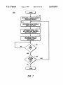
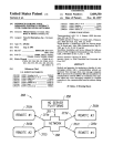
input includes a left single and double clicks and a right
single click. In bitmap 284. on the other hand. valid input
includes a left single and double clicks and a right single and
double clicks.
As shown by bitmaps 285, 286, 287, a drag operation
10
(e.g.. continuous depressing of a mouse button coupled with
movement) may be indicated as well. with appropriate user
motion suggested by arrows or other visual clues. Moreover,
the intelligent cursor of the present invention may also
provide screen information indicating a particular mode of
handle 243. Once the screen cursor is outside of the hit
operation (e.g.. “draw” mode). Bitmap 289, for example,
radius of the handle 243. for example it is inside the object
illustrates the available mode of operation (e.g.. “draw”
mode) as well as the pointing device inputs (e. g.. left single
and double clicks with drag. and right single click) which are
241 as shown by the cursor 225k of FIG. 3]. the screen
cursor reverts back to the default bitmap 230.
While the screen cursor is updated with a dilferent bitmap
currently available.
(e.g.. crosshairs of cursors 225]’, 225g) during the foregoing
As illustrated in FIG. 4G. the intelligent screen cursor of
the present invention may display other screen indicia,
operation, there is still no visual clue or indication to the user
of which pointing device input operations (mouse button
including additional graphic elements and/or alphanumeric
clicks). if any. are available at a given instance. In FIG. 3H,
information, to illustrate or convey available user inputs.
for example, the cursor 225f changes (e. g., into a crosshair)
Screen cursor bitmaps 291. 292. for example, include a
diamond graphic object to indicate an available double click;
to indicate a different mode of operation, such as enlarging
or shrinking the screen object 241. However, there is still no
indication to the user of how such an operation would be
achieved. Should the user perform a left mouse click or a
“drag” to effect the currently available operation? Thus,
25
even though a screen cursor may be updated with di?erent
bitmaps to indicate various modes of operation available to
the user. such updates do not indicate the particular action
unlike previously illustrated cursor bitmaps 282-284, single
click capability is not assumed. As still yet another example,
screen cursor bitmaps 291, 293. 294. and 295 include textual
information indicating available clicks (e.g.. “S” for single
click; “D” for double click). In a similar manner. keyboard
states (e.g., SHIFT, ALT, and CI‘RL) which are to accom
pany a mouse input may also be indicated.
which the user must undertake to accomplish the available
Referring now to FIGS. SA-B, the advantages of the
operation.
intelligent screen cursor of the present invention will be
illustrated. Both ?gures illustrate the interaction between a
INTELLIGENT SCREEN CURSOR
screen cursor and the scroll bar 217 of window 200. In FIG.
5A, as the screen cursor 225 touches diiferent components
Referring now to FIGS. 4-7, a user interface for the 35 of the scroll bar 217. there is no indication or feedback to the
user of what pointing device input(s). if any. are acceptable.
intelligent screen cursor of the present invention will be
In FIG. 5B. in contrast, the intelligent screen cursor 275
illustrated. In FIGS. 4A-E, the screen cursor operation of
1. User Interface
indicates the valid inputs of the pointing device at all times.
At position (1). for example. the cursor 275 displays the
bitmap 280. thus indicating only movement of the pointing
device is available. At position (2), the cursor 275 is updated
FIGS. 3A-E will again be illustrated, this time employing
the intelligent screen cursor of the present invention. In FIG.
4A. screen object 241 is again illustrated in the client area
220 of window 200; in this example. however. the move
ment of an intelligent screen cursor 275 towards the object
with the bitmap 281 to indicate that a left single click is a
241 (indicated by the dashed arrow) will be shown. As
illustrated in FIGS. 4B-E, as the intelligent screen cursor
275 moves towards the object 241. valid input operations
45
valid entry. At position (3), the cursor 275 is again updated,
this time with the bitmap 286, thus indicating valid pointing
device input includes left click and drag operations. Finally,
at position (4). the cursor 275 reverts back to the bitmap 281
to indicate to the user that a left single click is the only
275. In FIG. 4D. for example, a left mouse button of the
currently valid pointing device input (other than movement).
screen cursor 2750 is highlighted with a single caret 265 to
Referring now to FIGS. 6A-B, alternative embodiments
indicate that a left mouse click may be entered by the user
at this point in time. As shown in FIG. 4E, a double click of 50 of the intelligent screen cursor of the present invention will
be illustrated. In FIG. 6A, (which corresponds to previous
the left mouse button may be indicated by additional screen
FIG. 4D), the intelligent screen cursor 275 may be accom
indicia. such as a double caret 266, displayed within the left
panied by additional screen indicia, such as textual mes
button area of screen cursor 275d. In FIGS. 4B and 4C.
sages. Thus. as the cursor 275 touches the object 241, a
however. the mouse button 265 of cursor 275 is not high
screen message 301 is displayed to assist the user even
lighted (i.e., it is displayed as blank or empty) as there are
available to the user are shown directly by the screen cursor
no valid pointing device input signals available (other than
general movement of the pointing device).
As shown in FIG. 4F, exemplary pointing device input
may be indicated as follows. Bitmap 280 illustrates the
system context when no pointing device input is valid (other
than general movement of the pointing device). Bitmap 281
indicates a left single click. Bitmap 282. on the other hand.
further in understanding valid inputs and their conse
quences.
In a lesser preferred embodiment. shown in FIG. 6B, the
intelligent screen cursor of the present invention may pro
60 vide screen information at a region remote from the current
cursor position (e.g.. at a separate window). In this case, a
window 303 containing a functional bitmap (such as those
indicates a valid left single and double clicks. In this
from FIG. 4F) is operationally coupled to the screen cursor
225. Therefore. the intelligent screen cursor of the present
instance. a single click is assumed accompany a double
click; alternatively. each signal may be shown separately, as 65 invention may also employ remote graphical indicia, such as
feedback window 303. to indicate to the user which pointing
described hereinbelow. Moreover, signals from different
device operations are valid. As still yet another embodiment.
buttons may be indicated. In bitmap 283, for example, valid
5,655,093
9
10
pointing device 105 itself may provide this information, for
example. in the form of visual (e. g., LED or LCD) or tactile
From this information, the system may discern a set of
input device signals which are valid. In step 703, a screen
(e.g.. vibrating) clues. The pointing device information itself
cursor bitmap correctly illustrating the pointing device sig
may be provided in addition to or in lieu of the screen cursor.
nals available for input is determined. For example, if the
current hit-test code is HTREDUCE (cursor is positioned at
the window’s minimize button), the left single click cursor
2. Internal Operation
Referring now to FIG. 7, the internal processes of the
system 100 will now be described in detail. The operation of
the intelligent cursor is performed by an event-driven
method 700 which may be invoked by a message dispatcher
bitmap 2.81 is chosen. In step 704, the screen cursor is
updated with the bitmap determined to be appropriate (from
step 703). The actual updating may be accomplished by
employing Windows CreateCursor and SetCursor routines,
in response to user events, including keyboard and mouse
events. Moreover. the method determines user events (e.g.,
left button double-click) which are currently valid and
reports them to the user.
which are fully described in the above-cited Vfrndows SDK
materials.
In step 705, a loop is established to wait for the next user
By way of example, mouse events commonly occurring
within a window’s client area may be reported by the
following messages:
WMJBU'ITONDBLCLK
WM_LBU'ITONDOWN
WM_LBUTI‘ONUP
WIVLMBU'ITONDBLCLK
WM_MBU'ITONDOWN
WM_MBUTI‘ONUP
WM__MOUSEMOVE
Left button double click
Left button down
Left button up
Middle button double-click
Middle button down
Middle button up
Mouse Move
WM_RBUTTONDBLCLK
WNL_RBUTI‘ONDOWN
WLLRBU'ITONUP
Right button double-click
Right button down
Right button up
15 event, such as moving the screen cursor. If a user event has
20
25
Similar messages for mouse events occurring in non-client
areas are also available. Since the non-client area of a
window is maintained by Windows, however. these latter
messages are often safely ignored by a window object.
The dispatching of messages in an event-based system,
30
such as Microsoft Windows. is known in the art; see e.g..
Petzold, C.. Programming Windows, Second Edition,
Microsoft Press. 1990. Additional information can be found
35
The individual steps of the method 700 are as follows. In
40
What is claimed is:
1. In a computer system, an improved method for pro
viding feedback to a user, the method comprising:
array of picture elements (pixels);
querying Windows’ system settings. In step 702. the system
displaying on the user interface a cursor for indicating a
determines a context, including the current mouse cursor
45
position at a particular pixel on the user interface, said
cursor moving on the user interface in response to
movement of a pointing device by a user, said pointing
may be employed to query where a mouse cursor is posi
device including at least two user-activated buttons,
each which generates a ?rst signal when single clicked
by the user and generating a second signal when double
clicked by the user; and
as the pointing device is moved by the user, displaying
tioned on a window. The query returns a “hit-test code”
indicating the location. For example, a code of
HTVSCROLL indicates that the cursor is positioned on the
vertical scroll bar. HTCLIENT, on the other hand, indicates
that the cursor is positioned within the client area. Moreover,
a window object may include additional routines for testing
feedback to the user for indicating all combinations of
said signals which comprise valid input for each pixel
whether the screen cursor is within a prede?ned hit radius
operation (e.g., draw, edit, select, and the like) for the
system.
present invention is not limited to any one of the foregoing
displaying a user interface comprising a two-dimensional
a mouse device. is present. This is a simple matter of
and PtInRect routines) and/or determining a current mode of
include bitmaps of other input devices, including trackballs,
joysticks, light pens, and the like. Moreover, the present
invention may be advantageously implemented in a variety
of other UI platforms, including Macintosh, X-Windows,
exemplary embodiments but is instead de?ned by the fol
lowing claims.
step 701, the system determines if a pointing device, such as
for screen objects (e.g., employing Windows PtInRegion
certain alternatives. there is no intent to limit the invention
to that particular embodiment or those speci?c alternatives.
For example, the intelligent screen cursor of the present
invention has been illustrated with mouse device bitmaps.
Those skilled in the art, however. will appreciate that the
intelligent screen cursor of the present invention may
Motif, Next Step, and the like. Thus, the true scope of the
in Microsoft’s Window Software Development Kit, includ
ing: 1) Guide to Programming, 2) Reference, Vols. 1 and 2.
and 3) Tools, all available from Microsoft Corp. of
Redmond. Wash. The disclosures of each of the foregoing
are hereby incorporated by reference.
location and operation(s), currently available. In Windows,
for example, a mouse pointer message, WM_NCHITES1‘,
occurred and the user has not terminated the event loop (yes
at step 706), then the method loops back to step 702 for
updating the screen cursor, as necessary. Upon termination
of the session by the user (no at step 706), the method
concludes.
While the invention is described in some detail with
speci?c reference to a single preferred embodiment and
55
pointed to by the cursor as it moves across the user
interface.