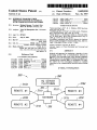
1
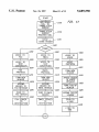
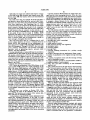
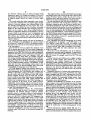
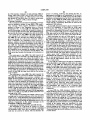
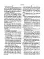
USOO5689550A
United States Patent [191
[11]
Patent Number:
Garson et al.
[45]
Date of Patent:
[54] INTERFACE ENABLING VOICE
MESSAGING SYSTEMS TO INTERACT
WITH COMMUNICATIONS NETWORKS
5,689,550
Nov. 18, 1997
5,351,276
9/1994 Doll, Jr. et a1. ........................ .. 379/67
5,406,557
4/1995
5,426,637
6/1995 Derby et a1. ..
5,440,624
8/1995 Schoof, II ............................. .. 379/202
[75] Inventors: Michael Garson. Cleveland. Ohio;
Baudoin
.. .. . . .. . . ..
. . . . . . ..
370/61
370185.13
OTHER PUBLICATIONS
Bruce D. Stewart. Sebastian. Fla.
“Interconnecting LANs”. R. L. Shanna. IEEE Spectrum,
Aug. 1991. pp. 32-38.
[73] Assignee: Voice-Tel Enterprises, Inc.. Cleveland.
Ohio
“B-ISDN and How it Works”. D. Delisle and L. Pelamour
gues. IEEE Spectrum, Aug. 1991. pp. 39-44.
[21] Appl. No.: 287,822
"Inside Routers: A Technology Guide for Network Build
[22] Filed:
ers”. R. Boule and J. Moy. Data Communications, Sep. 21.
1989. pp. 53-56. 59. 60. 65 and 66.
Aug- 8, 1994
6
_
[51] Int. Cl. ............................. .. H04M lltii?lggg
,
[52]
as. C]. ............................ .. 379/89; 348/15; 370/395;
[58]
Field of Search ................................ .. 379/89. 88. 67.
370/402; 379/32; 379/202; 379/207
379/94. 207. 204. 202. 32; 370/61. 85.13.
60.1. 352. 355. 395. 401. 402. 403. 404.
428; 348/15. 14
,
[56]
VoiceMemo Installation and Service Manual for Software
Release 5033’ Centigmm communica?ons Corp" San Jose.
Cahf" 2700-08854 R“ A‘ Dec‘ 1' 1993‘
Primary Examiner-Thomas W. Brown
Attorney, Agent, or Fime-Townsend and Townsend and
Crew LLP
[57]
ABSTRACT
Methods and apparatus for interfacing a plurality of voice
Refemnces C'ted
Us. PATENT DOCUMENTS
messaging systems with a communications network are
disclosed. Voice messages from voice message computers
4,914,586
I
4/1990 Svvmehart et a]. .................. .. 379/96 X
450 are processed by an interface 410 and transmitted over
communications network 390 to its dcs?nau'om The intcp
5,289 468
551mg?’ Jr‘ et a1‘
2/1994 Yosliidi
""""""
face allows the voice messaging computers to establish
cc’mcc?‘m t° thc communicatmns “work with“ dialing
"""
.'.‘...m370/85.l3
5,309,437
5/1994 Pedman et a1. .
5,333,266
7/1994 Boaz ...... ..
.. 370/8513
379/94 X
5,341,374
8/1994 Lewen et a].
370/854
[ 310a
REMOTE #1
mt“ "
25 Claims, 13 Drawing Sheets
PLATFORMS
351 ‘
31 j \
5
310g
NETWORK
3110
k 390
311d
3100
REMOTE #3
311;
[3105
US. Patent
Nov. 18, 1997
Sheet 1 of 13
110 \
APPLICATION
f 120
___1_____ma
APPLICATION
LAYER
PRESENTATION
LAYER
L
PRESENTATION
LAYER
SESSION
LAYER
1406
___1__..
SESSION
LAYER
TRANSPORT
LAYER
140a
_._i_____
TRANSPORT
LAYER
NETWORK
LAYER
.1406’
E
NETWORK
LAYER
DATA LINK
LAYER
PHYSICAL
5,689,550
LAYER
1402‘
,
I
140g
‘A—_
DATA LINK
LAYER
PHYSICAL
LAYER
LAYER
\iaa
US. Patent
Nov. 18, 1997
Sheet 2 0f 13
210
(T210
APPLICATION
oggiagqs
110 \
PH
SESSION
LAYER
REDUCTION
DATA
APPLICATION
LAYER
OATA uNIT
PRESENTATION
LAYER
SH
I
SESSION
LAYER
TH
TRANSPORT
LAYER
LAYER
NETWORK
LAYER
DATA LINK
LAYER
[120
APPLICATION
OATA
AH
PRESENTATION
LAYER
220
APPLICATION INQAJMIQG APPLICATION
CONSTRUCTION
APPLICATION
LAYER
TRANSPORT
5,689,550
NH
F A c
NETWORK
LAYER
OATA uNIT
OATA UNIT
PHYSICAL
LAYER
OATA LINK
LAYER
FCS F
PHYSICAL
LAYER
BITS
L32
FIG. 2
300\
[350
HO SERVER
PLATFORMS
3100
351\
311a
3””
REMOTE #3
3110
[3106
REMOTE #4
US. Patent
Nov. 18, 1997
[425
420
ethernet
REACT
VOICE-TRAC
SERVER
modern
5,689,550
Sheet 3 of 13
/ 490
430
I 390
REACT
EMAIL
495
SERVER
450
CENTIGRAM
VOICE MEMO ll
PROCESSOR
4505K r
[410
REACT
T
45001 COMMUNICATIONS
450
_
TYPICAL
ATM
BASED
NETWORK
i
__
SERVER
PT :
Ch 1-16
ASYNC
(NIB)
DDCNP
REACT
FAX
sERvER
L__—___J
NETWORK i
CONNECTION
TO WAN/GAN
[440
FIG. 4
TOPOLOGY
US. Patent
Nov. 18, 1997
Sheet 4 of 13
5,689,550
2m .
5%\
mjoz 03 E0 4
xmogzmoE zH 1éo5Em8z
H
NE E
\QQR
Evm
o~E5zo0u
mG?‘
__
m5:j<o
H
Q5/
gm
moz moi?zH
z<mocu
US. Patent
Nov. 18, 1997
Sheet 5 of 13
3E2? m>mw
.NECZMH
5,689,550
mmm
128m: Qm<m VEOBZ
2:‘
5Iowa; 82 0 ~E> m
582L3
gm
US. Patent
Nov. 18, 1997
‘
Sheet 6 0f 13
START
>
VMS INITIATEs / 71 0
CONNECTION
VMS SENDS
/ 7?”
CALL TO NIB
NIB STORES
CALL
/ 730
NIB INITIATEs /740
TCP CONNECTION
NIB TO
/ 750
DESTINATION NIB
CALL TRANSFERRED
750
TO DESTINATION /
NIB
DESTINATION NIB
sENDs CALL To /
DESTINATION VMS
FIG. 7
77o
5,689,550
US. Patent
Nov. 18, 1997
Sheet 7 of 13
INITIALIZE / 8005
NIB
I
USER CALLS /
5010
l
VMS FORWARDS / 5020
CALL TO NIB
NIB ASSIGNS / 5030
CALL 10 TO CALL
NIB ACCEPTS /5040
CALL
NIB EXAMINES /’ 5050
CALL HEADER
NIB PERFORMS
PROTOCOL /
B050
TRANSLATION
NIB QUEUES
CALL TO /
8070
WAN
NIB OPENS
8080
TCP CONNECTION /
NIB RETRIEVES
805,0
CALL FROM /
MEMORY
6)
FIG. 8A
5,689,550
US. Patent
Nov. 18, 1997
Sheet 8 of 13
DESTINATION
NIB RECEIVES
CALL
NIB RELEASES
TCP CONNECTION
DESTINATION NIB
STRIPS TCP
HEADER
DESTINATION NIB
QUEUES TO
VMS
NIB OPENS
CONNECTION +
DELIVERS CALL
TO VMS
VMS STORES
IN DESTINATION
MAIL BOX
FIG. 8B
//a120
5,689,550
US. Patent
Nov. 18, 1997
(
START
Sheet 9 0f 13
)
HELLO
l
DATA LINK
LAYER
CONNECTION
I
NETWORK
LAYER
CONNECTION
I
TRANSPORT
LAYER
CONNECTION
I
APPLICATION
LAYER
CONNECTION
T
BEGIN
APPLICATION
l
SEND
DATA
T
END
APPLICATION
I
CLOSE
APPLICATION
LAYER
TERMINATE
LINK WITH,
NIB
FIG. 9
5,689,550
US. Patent
Nov. 18, 1997
HELLO
Sheet 10 0f 13
/jm
I
OATA LINK
LAYER CONNECTION /
1020
I
NETWORK LAYER
/1030
CONNECTION
I
TRANSPORT LAYER
,0
CONNECTION
/ 40
APPLICATION
LAYER
CONNECTION
1050
/
I
BEGIN
APPLICATION
1050
/
I
SEND
OATA
/
1070
I
ENO
APPLICATION
I
/1030
INFOggAVI-IR
CALL s
0F MESSAGE DELIVERY /”55
I
CISEII
ON
LAYER
APPL
TERMINATE
LINK
@9
FIG. 10
/
1090
/ 10.95
5,689,550
U.S. Patent
Nov. 18, 1997
NIB SENDS
CALL TO
Sheet 11 of 13
/”05
5,689,550
FIG. 11
TRANSLATION
SERvER
l
TRANSLATION
SERvER
RECEIVES CALL
/m0
I
STRIP +
1115
STORE HEADER /
1400
VOICE TO
FAX
l
1205
VOICE TO
TEXT
CONVERSION
1210
FAX
PROTOCOL
1215
FORM NEW
HEADER
I
APPEND
HEADER TO
FAX MESSAGE
1220
|
1225
1
1305
1230
HEADER
I
VOICE TO
vOIcE
1
VOICE
PROTOCOL
1405
1310
1410
FORM NEw
HEADER
/1315
FORM NEW
SEND TO
FAX SERVER
FAX SERVER
TO
DESTINATION
vOIcE TO
EMAIL
T
VOICE TO
TEXT
CONVERSION
I
EMAIL
PROTOCOL
l
1415
APPEND HEADER
1320
TNOE 8213x1605
APPEND
‘
HEADER To
FORM TCP/IP
EMAIL MESSAGE
HEADER
l
1325
1420
I
r1425
SEND TO EMAIL
APPEND TCP/IP
SERVER
HEADER
l
EMAIL SERVER
T0
1330
l
SEND T0
d NIB
DESTINATION
#435
d NIB TO
vMS
END
V
1430
U.S. Patent
Nov. 18, 1997
Sheet 12 of 13
VMS SENDS
CALL TO NIB
NIB CREATES
ORIGIN CDR AND
ORIGIN CALL FILE
T
NIB SENDS
CALL TO DESTINATION
NIB
DESTINATION NIB
CREATES
DESTINATION CDR
DESTINATION CALL FILE
T
NIB SENDS TO
DESTINATION VMS
T
DESTINATION VMS
CONFIRMS
DELIVERY
T
DESTINATION NIB
SENDS CONFIRMATION
TO ORIGIN NIB
DESTINATION CALL
FILE IS DELETED
DESTINATION CDR IS
"AGED" AWAY
T
ORIGIN NIB
RECEIVES
CONFIRMATION
T
ORIGIN NIB
DELETES ORIGIN
CALL FILE
T
ORIGIN NIB
QUEUES
ORIGIN CDR FILE
@5
FIG. 12%
5,689,550
US. Patent
Nov. 18, 1997
Sheet 13 of 13
TCP
CONNECTION
/- 1280
SEND CDR
TO NMS
FIG. 12B
@
CHANGE MASTER
1310
NETWORK
/
DATA BASE
|
UPDATE RECORD
1320
ADDED To
/
UPDATE QUEUE
I
UPDATE sENT /1330
To NIB
I
NIB RECEIVES /1340
UPDATE
1
NIB
1350
ACKNOWLEDGES /
l
NMS DELETE
1 50
UPDATE FROM / 3
QUEUE
@
FIG. 13
5,689,550
5,689,550
1
2
INTERFACE ENABLING VOICE
MESSAGING SYSTEMS TO INTERACT
WITH COMMUNICATIONS NETWORKS
herein may be realized by reference to the remaining por—
tions of the speci?cation and the attached drawings.
BRIEF DESCRIPTION OF THE DRAWINGS
BACKGROUND OF THE INVENTION
FIG. 1 illustrates the 081 Reference Model;
FIG. 2 illustrates data transfer in the 081 Reference
The present invention is related to the ?eld of telecom
munication. In particular. the present invention provides an
interface that enables voice messaging systems to interact
with communications networks.
Voice messaging systems (VMSs) are known in the art of
telecommunications. Such VMSs have internal mass storage
capabilities to assist in the processing of calls. For example,
Model;
FIG. 3 illustrates the topology of the communications
network according to the present invention;
FIG. 4 illustrates hardware architecture of the Network
Interface Box (NIB) according to the present invention;
FIG. 5 illustrates the software architecture of the NIB of
VMSs allow callers to leave messages for a call recipient
FIG. 4;
who is not able to receive a call. The caller‘s message is
FIG. 6 illustrates the hardware architecture of the network
stored in the recipient’s “mailbox” for retrieval by the
management site;
recipient at a later time. A mailbox refers to the location in
a central memory device assigned to a speci?c user or
recipient. Each user in the system is assigned its own
mailbox. which is accessible only by the assigned user. In
addition. VMSs route incoming calls to the appropriate
extensions and provide intra-ot?ce and inter-o?ice messag
20
ing services.
Typically. a user interacts with a VMS through Touch
Tone keys of a telephone keypad. By depressing the appro
25
priate keys. the user can control message delivery and
retrieval. In some systems, voice prompts may guide the
user through the various VMS functions.
In practice. VMSs are linked to private branch exchanges
(PBX). This allows VMSs to take advantage of services such
FIG. 7 is a ?ow chart illustrating the procedure for
effecting a message exchange from an originating VMS to
the destination VMS;
FIGS. 8a-8b are ?ow charts illustrating the procedure for
effecting a message exchange from an originating VMS to
the destination VMS in greater detail;
FIG. 9 is a ?ow chart illustrating the procedure for
forwarding a message by an originating VMS to the NIB;
FIG. 10 is a ?ow chart illustrating the procedure for
forwarding a message by a destination NIB to the VMS;
FIG. 11 is a ?ow chart illustrating the procedure for
message translation;
FIGS. 12a-l2b are ?ow charts illustrating the archiving
as automatic call forwarding on no answer. as well as other
procedure according to the present invention; and
functions provided by the PBX. Of particular interest to the
present invention is the ability of VMSs to automatically call
designated stations and deliver messages stored in the elec
FIG. 13 is a ?ow chart illustrating the procedure for
updating a network database by the Network Manager.
tronic mailboxes.
PBXs are on premises telephone exchange systems
capable of both voice and data connections. Typically. a
TABLE OF CONTENTS
35
I. General
II. System Architecture
PBX provides a point of interconnection for telephone
a. General
extensions or systems within the o?ice and a trunk connec
b. Remote Site Hardware Architecture
c. Remote Site Software Architecture
tion to the nearest central o?ice telephone exchange. Calls or
transmissions within the o?ice are made through the PBX;
calls outside the o?ice are directed by the PBX to the public
telephone network.
By interconnecting VMSs at remote locations through the
public telephone network. messaging services between mail
cL Network Management Site
III. System Operations
a. Message Transfer
45
b. Message Translation
c. Archiving and Deleting Call Files and CDR Records
d. Updating Network Database
boxes maintained at each location are provided. In this
con?guration. access to a remote VMS is achieved via a
modem (i.e.. dialing. connecting. and transferring the mes
sage to the remote VMS). This is cumbersome. time
consuming. and not cost e?ective. It is desirable. therefore.
to provide a more et?cient method and device for delivering
50
I. General
The present invention provides an improved communica
messages to another VMS.
SUI/[MARY OF THE INVENTION
DESCRIPTION OF THE PREFERRED
ENIBODIMENT
SS
Improved devices and methods of voice messaging are
tions system for sending and receiving voice messages over
a communications network. Before describing the invention
in greater detail. it is helpful to ?rst describe general
provided by virtue of the present invention. According to
networking principles.
one embodiment. a voice messaging processor which pro
vides voice messages is linked to an interface. The interface
The basic concern of networking is the ability of the
systems within the network to interoperate with each other.
receives messages from the voice messaging processor
according to a ?rst protocol. The interface processes the
message. which includes translating the ?rst protocol to a
To address this concern. standards have been established to
provide some uniformity in the world of communications.
These standards establish the protocols which systems use to
communicate with each other. The following is a brief
description of the communications standards according to
second protocol. As a result. the message can be transmitted
across a communications network to its destination. The
interface improves the quality and quantity of messages
which are sent over a wide area network. A further under
the Open Systems Interconnection Reference Model. The
model contains seven layers. each layer or protocol de?ning
standing of the nature and advantages of the inventions
di?‘erent functions.
65
5 ,689,550
3
4
The Physical Layer handles bit-transmission between one
node (e.g.. host. workstation) and the next. The Physical
OSI model. each layer will have its own protocol. Typically,
the protocols function on a peer-to-peer basis between each
of the layers as indicated by the logical (or virtual) com
Laym‘ functions include interfacing with the transmission
media; encoding the data signal; de?ning the range of the
voltage or current magnitudes; de?ning the connector sizes.
shapes. and pinouts; and any such function that is generally
associated with the physical transmission of the bit stream.
The Data Link Layer maintains a reliable communication
link between nodes. As such. it assumes that the Physical
layer is noisy or prone to errors. Data Link provides a
munication paths l40a-g. The interface between the layers
within the same system is a vertical relation. whereas the
protocol is a horizontal relationship between peer layers of
the adjacent system. Communication between two systems
is effected in the following manner. A user inputs data such
as electronic mail message in the Application Layer of
10
reliable delivery mechanism to transmit frame (or package)
of data bits to the next node. Data Link Layer inserts
addresses into the ?ame (including source and destination)
and provides aror control for the data. Error control may be
implemented. for example, with a Cyclic Redundancy
FIG. 2 illustrates in detail the process in which data are
Check (CRC) or other error detection technique.
The Network Layer establishes a path for the traveling
data packet along the communication subnet from the source
node to the destination node. The Network Layer switches.
routes. and controls the congestion of these information
packets within the subnet.
transported from host system 110 to destination system 120
through a physical medium 180. Data from an Application
Process 210 in system 110 is passed to the application layer
20
passed to the Presentation Layer. The Presentation Layer
same way that the Data Link Layer assures reliable delivery
treats the data unit as its own data. appends the Presentation
of frames between adjacent nodes. The major difference
between the Data Link and Transport Layers is that the Data
Link domain lies between adjacent nodes. whereas the
net. Issues concerning source-to-destination messages are
Header (PH) and passes the data unit down to the Session.
Transport. and Network Layers in turn. With each successive
transfer. the data is encapsulated with the respective layer’s
header (i.e., SH, TH. and NH).
30
The same process occurs when the encapsulated data
reaches the Data Link Layer. The Data Link Header gener
important in the Transport Layer. For example, the Transport
layer segments a long message into smaller units (packets)
prior to transmission and assures the reassembly of those
packets to form the original message at the receiver's end.
The Session Laym' establishes and terminates process-to
process communication sessions between hosts. Translation
protocol. The Application Layer appends its Application
Header (AH) to the application data. The AH contains
protocol control information necessary for a peer Applica
tion Process 220 to interpret the data The data unit is then
The Transport Layer provides reliable delivery of host
messages originating at Layer 7. the application layer. in the
Transport Layer’s domain extends from the source to the
destination (or end-to-end) within the communication sub
system 110 (host) for transmission to the Application Layer
of system 120 (destination). The message proceeds down
through the seven layers (from the Application Layer to the
Physical Layer) of system 110, across cable 180. and up the
seven layers (Physical Layer to the Application Layer) of
system 120.
ally comprises Framing (F). Address (A). and Control (C)
information. In addition, the Frame Check Sequence (FCS)
35
between name and address databases. as well as synchroni
zation between the two hosts. may be required to manage the
sessions.
and/or additional Framing (F) characters are added as the
Data Link Layer trailer. The assembled frame is then passed
to the Physical Layer wherein the data are encoded for
transmission. Next, the Physical Layer accesses the trans
mission medium and monitors the serial bit transmission. At
the destination node. the reverse of this process occurs. The
Physical Layer hands its bits to the Data Link Layer. which
decodes and then strips off the Data Link Layer header and
trailer. The Data Link Layer data unit is then passed to the
Network. Transport. Session. and higher layers in turn. This
process is completed when the original data is presented to
the Application Process 220.
The Presentation Layer establishes the syntax (or form) in
which data are exchanged between the two hosts. As such,
the Presentation Layer provides a data manipulation
function. not a communication function. Data compression
and data encryption are two examples of Presentation Layer
services.
In practice. numerous LANs are linked together to form.
for example. an “internet.” Each LAN or subnetwork is
The Application Layer provides end-user services. such as
Applican'on Layer ?le transfers. electronic messages, virtual
linked to a backbone network capable of high bandwidth.
terminal emulation, and remote database access. The end
user interacts with the Application. In this manner. the
various other layers appear to be transparent to the end user.
The seven layers are divided into two subsets. The ?rst is
The backbone network is sometimes referred to as wide area
comprised of the lower three layers (the Physical. Data Link.
referred to in the art as a “router”. The router operates at the
and Network layers). These layers are sometimes referred to
“communication subnet" and logically separates the subnet
network (WAN). Generally. the individual LANs are inter
connected to the WAN by a switching router. switching hub.
or the like. Such interconnecting device is commonly
as the “communications subnetwork”. subnet. or the carrier 55 works. Routing tables, which inform the router of the WAN
portion of the system. The upper three layers (Session.
Presentation. and Application layers) are collectively known
topology. provide the information needed to route the data to
its destination. In large networks, the data may travel
as the host process or customer porion of the system. The
through many intermediate nodes before reaching its desti
middle layer (Transport) is the ?rst end-to-end layer and acts
nation. Various methods for transmitting data over commu
as a buffer between the two subsets. Generally, the Transport
nications networks. such as packet switching. are known. In
packet switching, data are transmitted in blocks called
packets. The uppa bound limit on the length of the packets.
for example, may be about 1000 octets (bytes). If a message
Layer is often grouped with the upper layer as part of the
host process.
FIG. 1 illustrates a simple local area network (LAN)
comprising two systems. As depicted. system 110 is linked
to system 120 by a physical medium 180 (i.e.. cable) to form
the LAN. The systems communicate or interact with each
other through a set or suite of protocols. Consistent with the
65
exceeds the limits. it is broken into a series of packets. Each
packet consists of a portion of the data that a system wants
to transmit and a packet header that contains controls
information necessary for the network to route the packet to
5.689,55O
5
6
their intended destination. In large networks. the packet may
be routed through a plurality of nodes before it reaches its
TCP/IP and UNIX, Addison-Wesley Publishing. Jan. 19.
1993. incorporated herein by reference for all purposes.
destination. At each node on route. the packet is received.
stored brie?y. and passed on to the next node. Eventually. all
the packets that comprise the message will be delivered to its
intended destination. There are two approaches. datagram
and virtual circuit. which are implemented by networks to
LAN 490. for example. may be an Ethernet. Alternatively.
token ring. FDDI. or other LAN may be used. Router 495.
for example. may be a digital computer of the type that is
5
well known to those skilled in the art such as a RISC
Networking Processor. In one embodiment. the router net
works TCP/IP data and determines the network tra?ic ?ow.
handle the stream of packets as it is routed to its destination.
In the datagram approach. each packet. which is referred
Generally. the path selection is made from several paths
based on 1) information obtained from speci?c protocols. 2)
algorithms that attempt to identify the shortest or best path.
to as a datagram. is treated independently. with no reference
to packets that have previously been sent. Each intermediate
node chooses the datagrarn’s next path. taking into account
information received from adjacent nodes such as tra?ic.
line failures. and others. As a result. each datagram may
travel different paths even though they contain the same
destination address. Additionally. the datagrams may arrive
in Miller. Internetworking, A Guide to Network
Communications, M&T Books. Feb. 19. 1991. incorporated
herein by reference for all purposes.
at the destination out of sequence. or some may even be lost
The LAN includes a communications server 410 which
and 3) other criteria such as metrics or protocol-speci?c
destination addresses. A discussion on routers can be found
during transit. In some networks. the destination node is
interfaces a VMS 450 with the WAN. Communication
responsible for reordering the datagrams and informing the
Server 410 is referred to elsewhere herein as the “Network
source node to resend the lost data. The datagram approach 20 Interface Box" or “NIBTM”. The NIB includes a digital
is referred to as a “connectionless-mode” transmission. In
computer of the type readily known to those sln'lled in the
other words. units of data are transmitted from the sotn'ce to
the destination without establishing a route or connecting to
art. In some embodiments. the computer is based on current
INTEL 486 technology. although it will be apparent to those
skilled in the art that a wide variety of digital computers.
it.
On the other hand. the virtual circuit approach establishes
25
such as IBM AIX and RES6000. INTEL Pentium. and DEC
ALPHA. can be utilized without departing from the spirit of
the invention herein. According to one embodiment. the
INTEL 486 computer may be installed with Santa Cruz
30
Runtime System (includes SNMP agent). and/or CH lan
guage using RDBMS and Object Oriented Protocols which
a preplanned route before any packets are sent. This route
serves to support a logical connection between the source
and destination node. Once the route is established. all of the
packets are sent using the same route. In this manner. the
packets arrive at the destination in the correct sequence. This
Operation (SCO) UNIX Operating System. SCO TCP/IP
approach is referred to as a “connection-mode”
transmission. which means that a route between the source
and destination is established prior to the transmission. A
more detailed discussion on networking principles may be
found in Miller. lntemetworking, A Guide to Network
Communications, 1991. incorporated herein by reference for
all purposes.
11. System Architecture
a. General
FIG. 3 depicts the general architecture of the communi
cation system 300 disclosed herein. As shown. a plurality of
remote sites 31011-31011. each having voice messaging
capabilities. are attached to a communications network 390
by links 3110-31111 respectively. Each remote site is
assigned a unique network address or node id. The network
address associated with each voice message determines
which remote site receives the message. A network man
are managed by RAIMA and SCO FoxPRO Data Base
Management Systems to facilitate communication between
the VMS and the WAN. Santa Cruz Operations is a corpo
35
ration located in Santa Cruz. Calif. Information regarding
SCO UNIX and SCO TCP/IP Runtime system can be found
in the SCO Manual Set available from SCO. part number
BJOIZOSPOOI. published by P-H on Apr. 19. 1993. This set
includes SCO UNIX Operating System: System Administra
tors Guide, part number AUOlZllPOOl; SCO UNIX Oper
ating System: User’s Guide, part number AU01210P0O1;
SCO TCP/IP Runtime System for SCO UNIX Systems:
Command Reference; part number AUO2802P001; SCO
TCP/IP User's Guide, part number AUOZSOZGOOZ; SCO
TCP/IP Runtime Systemfor SCO UNIX Systems: User’s and
Administrator’s Guide, part number AU02801P001; and
SC'O UNIX Operating System: System Administrator’s
agement site 350. which also is assigned a unique network
address. is connected to network 390 by link 351. The
network management site monitors and manages the net
Reference, part number AU01213P001. all incorporated by
voice messages to one or more subscriber(s) located on the
Calif. although it will be apparent to those skilled in the art
that VMSs manufactured by other vendors such as Octel
Voice mail or NTI (Northern Telecom. Inc.) Meridian voice
reference for all purposes.
50
In one embodiment. VMS 450. is a Centigram Voice
work. In this manner. subscribers of one remote site can send
memo II manufactured by Centigram Inc. of San Jose.
other remote sites.
b. Remote Site Hardware Architecture
FIG. 4 illustrates a remote site in detail. The remote site
comprises a LAN 490 interconnected to communications
network 390 by a router 495. Communications network 390
may. for example. be a wide area network WAN of the type
that is well known in the art such as Asynchronous Trans
mission Mode (ATM). frame relay. or other network. In one
embodiment. data are transmitted through the WAN using
the Transmission Control Protocol/Internet Protocol (TCP/
1?) suite. The TCP/IP suite. for example. may be encom
passed by the entire protocol suite of ATM technology. This
includes ATM. frame relay. ISDN. Broadband ISDN. SMDS
and other network. A description of TCP/IP can be found in
Michell and Quarterman. Practical lntemetworking with
mail may be employed. The communication protocol
employed by the Centigram Voicememo H is a variant of the
Digital Data Communication Message Protocol (DDCMP)
developed by Digital Equipment Corporation. The opera
tions of Voicememo II are described in Centigram Opera
tions Manuals provided by Centigram Inc. of San Jose.
Calif. while DDCMP is described in detail in Tanenbaum.
Computer Networks, Prentice Hall Publishing, 2nd Edition.
1988. all incorporated herein by reference for all purposes.
The NIB communicates with VMS 450 through. for
example. an asynchronous link. In some embodiments. the
NIB provides up to 16 asynchronous links 460a-460p for
communicating with the VMS.
5 ,689.550
8
7
Call Files database 5410 contains the actual voice mes
Optionally. the remote site includes other devices such as
a voice-trak server 420. electronic mail (email) server 430.
and fax server 440. The various devices are interconnected
via LAN 490.
The email server may. for example. be of the type that is
well known to those skilled in the art. such as Lotus Notes.
sage from the voice messaging processor. When the voice
messaging processor executes a call. it is stored in a separate
call ?le which comprises the application layer header infor
mation and compressed voice data for the call. Each call ?le
is assigned a unique ?lename by the origin NIB. In one
embodiment. the ?lename format comprises the voice mes
saging processor node id (4 octets) followed by a 6 octet
Discussion on Lotus Notes may be found in Pyle. Creating
Lotus Notes Application, Que Publishing, Ian. 19. 1994.
sequence of numbers. The ?lename also serves as the
incorporated herein by reference for all purposes. The email
server connects. through the network. to all compatible
“callid” used as the key in the CDR database to store details
about the call.
email services such as MCI Mail. The fax server. which also
is well known in the art. connects via the network to all
group 3 or group 4 compatible faxes. A discussion of group
3 and group 4 faxes can be found in Gri?iths. ISDN
Explained. John Wiley & Sons. 1990. incorporated herein by
15
may include the following information:
a) callid. which corresponds to its call ?le name;
b) message status code;
c) message type (voice or greeting);
reference for all purposes. The email and fax servers enable
users to forward email and fax transmissions. similar to
voice messages. throughout the network.
The voice trak server may be a computer that is well
known to those skilled in art such as a computer based on 20
current INTEL 486 technology. In one embodiment. the
voice trak server is installed with VOCAMTM software from
server performs administrative and accounts receivable
25
requested);
k) length of message plus any attachments (frame count);
1) number of attachments to the original message (message
count);
establish links to other public or private switched networks.
‘The modem. which may be a v.32 bis type or other that is
well known to those skilled in the art. is connected to the
In) number of recipients on the node the message is being
sent to (distribution count);
voice track server's COM 1 or other asynchronous port. The
modem may also provide an alternative way for accessing
the WAN. Thus. data can be sent/received to/from NIBs not
FIG. 5 shows the architecture of the NIB software. A call
server module 5100 controls the overall operations of the
NIB. Call server 5100 interfaces with Con?g 5110. CDR
5120. and Network 5130 databases. which serve as infor
mation servers. A VMS Interface module 5500 and a Net
work Interface module 5400 facilitate data transfers between
the VMS and the WAN. A Call Files database 5410. which
stores the voice messages. is linked to both voice VMS and
WAN interfaces. ATimer module 5300 serves to inform the
g) destination node;
h) message number;
i) message Type;
j) message handling instrucn'ons (i.e.. priority. receipt
In some embodiments. a modem 425 may be provided to
linked to the WAN.
c. Remote Site Software Architecture
d) origin Node ID;
e) origin mailbox number;
f) date and time message was originated;
Voice-Tel Enterprises. ‘Through VOCAMTM. the voice trak
functions. such as generating reports. network tra?ic
statistics. and other functions.
The CDR database (cdr.ddl) contains detailed information
for each voice call. It also contains an associated delivery
record for each destination mailbox for which the call is
destined. The call record and mailbox records collectively
35
n) separate database records for each destination mailbox;
o) mailbox number of each recipient;
p) date. time. and status of delivery to each destination
mailbox; and
q) retry counter for use by the call server in error recovery.
The Network database (net.ddl) contains one record for
each voice message processor node in the network. The
40 record defines the network address associated with the node
on the communications network. The database also contains
a record for each NIB in the network. which associates the
NIB with its network address. For the NIB(s) containing the
network manager. the database also contains the queue of
Call Server when a prede?ned time interval has expired. A
network database updates that are being distributed by
Logger module 5200 accepts preforrnatted log messages
network manager. Once all NIB updates have been
completed. this queue will be empty.
The Log database (log.ddl) contains one record for each
from the Call Server and stores them in in Log database 5210.
In some embodiment. the Logger also displays the log
messages on the Log console. An Operator Interface 5600
loggable event that has occurred on the NIB. In some
provides an interactive interface between the NIB and a user 50 embodiments. a loggable event is de?ned by the header ?le.
A loggable event. may. for example. be the delivery of one
to. for example. examine the status of the NIB or issue NIB
call orVMS message. The record contains an event code. the
commands.
date and time the event occurred. and a text message
The databases are written as Raima DDL ?les.
describing the event. For consistency with the database
Accordingly. the name of the databases will be in form
nameddl. The functions and contents of the various data SS maintained by the network manager. each record also
includes the node id of the NIB.
bases will now be described in detail.
The software architecture also includes de?nition ?les
Con?g database (cfgddl) 5110 contains information that
which are used by the various software modules. Such
de?nes the operating parameters of the NIB. In some
de?nition ?les are referred to as “header ?les." According to
embodiments. the information may be contained in one ?le.
The operating parameters. for example. include: the voice
one embodiment. theNIB includes servenh. asci.i.h. strans.h.
messaging processors node name. NIB network address.
current version of the NIB software. the name of the various
databases (CDR. Network. and Log). address of the Net
work Manager. number of TCP senders. number of TCP
receivers. number and con?guration details of the voice
messaging ports. and current values of the various operating
events.h. and centigramh header ?les.
parameters.
Servenh de?nes general purpose constants and macros
used by all the NIB’s software modules and ascii.h de?nes
65
ASClI constants which are well known in the art The
strans.h header ?le de?nes transactions that are used
between software tasks on the NIB. Generally. each trans
action is associated with its own parameters. Communica
5 .689,550
9
10
The Logger (tcclogc) accepts preformatted log messages
tion between software tasks are effected through UNIX
interprocess queues. The format and contents of a block of
and displays them on the console along with a date and time
stamp. The Timer (timenc) noti?es the call server when a
data passing through these queues are governed by stransh.
prede?ned timer interval has expired. The timer interval is
de?ned in the record contained in the Con?g database.
In addition. stransh de?nes the values for various status
bytes.
The eventh header ?le de?nes reportable events. includ
In some embodiments. the NIB software architecture may
ing event type. reporting level (not logged. logged locally.
include an Interactive NIB Con?gurator (nibsetupc). The
nibsetup is separate from the other software modules and is
used during initialization of the NIB. Nibsetup provides an
reported to network manager). and contents/format of the
test message accompanying the event report. The centi
gramh header ?le de?nes the data structures and header
10
interactive menu driven interface for a user to con?gure and
format for the VMS DDCMP and messaging protocols.
which can be found in Voice Memo Design Reference
Manual, Con?guration Manual, and Installation & Service
Manual, which are provided by Voice Tel Enterprises and
view the Network (net.ddl) and Con?g (cfg.ddl) databases.
Also. the nibsetup initializes the Call Detail (cdr.ddl) and the
local Log (log.ddl) databases. A more detailed description of
are incorporated herein by reference for all purposes. The
NIB software also includes utiLc and log.c utility ?les.
These ?les provide general purpose functions for the various
software modules.
Tel Network Interface Box (NIB) Software Speci?cation.
Mar. 8. 1994. Software Version: 4.1. incorporated herein by
the NIB’s software architecture can be found in TCC/Voice
reference for all purposes.
d. Network Management Site(s)
The various software modules will now be described in
detail. According to one embodiment. the software modules
FIG. 6 illustrates the network management site in detail.
The administrator site includes a LAN 690 linked to the
WAN 390 by a router 695. The LAN. for example. com
are written in C. using SCO UNIX C development system.
The name of the source ?le for each software module will be
in the form name.c.
prises a network management station 620. a mainframe 610.
The Call Server (servenc) controls the operation of the
NIB. At system start up. the Call Server loads con?guration
data from the Con?g database. The data represent operating
translation server 650. and video-conference and multi
a catcher network server 630. an identi?er server 660. a
media server 640.
The LAN. in some embodiments. may be an Ethernet.
parameters of the NIB. The Call Server creates interprocess
queues for tasks that are to be performed by other software
modules (i.e.. Logger. Timer. and Operator. VMS. and
Network Interfaces). These taslm. for example. comprise:
call routing. including address translation from VMS pro
tocol to WAN protocol; managing end-to-end call queuing;
transferring calls across the WAN; managing and updating
the Call Detail Recording database. Log database. system
although other networks may be employed. Communication
between the LAN and WAN 390 is e?fected through a router
30
based on current INTEL 486 technology. In some
embodiments. the computer functions on a Santa Cruz
Operation’s UNIX operating system and/or C-H- language
using RDBMS and Object Oriented Protocols. The Catcher
status and error logs; and reporting system status to the
requesting operator or network manager tasks. Such tasks
are initialized and terminated by the Call Server.
The VMS Interface manages data transfers between the
NIB and the VMS via the asynchronous ports (up to 8). In
some embodiments. the VMS Interface may comprise two
Network server receives the call detail report (CDR) records
which are sent from the NIB remote sites. The Catcher
Network server then stores the CDR records in the Network
Archive database.
Mainframe 610 may be Proliant 4000 manufactured by
Compacq Computer Corp. In one embodiment. the main
frame is equipped with VOCAMTM software from Voice-Tel
subtasks or procedures. centrxc and centtx.c. Centrx man
ages the receive side of the VMS port on the NIB. Centrx
accepts complete messages from the VMS and forwards
them to centtx for processing. which includes issuing appro
priate responses back to the VMS. Centtx performs data
transfers and communications to the VMS. including pro
tocol responses at all levels of the VMS protocol.
Additionally. centtx interacts with the Call Server and the
Call Files database for reading/writing voice call ?les. In one
embodiment. one centrx/centtx pair regulates data transfers
in each VMS asynchronous port.
45
Identi?er server 660 may. for example. be an program
mable computer with an Intel Pentium processor. In some
50
The Network Interface oversees the communication
cation over the WAN. Netsend sends UDP datagrams over
the WAN network to another NIB. Netrecv receives UDP
datagrams from another NIB and queues them to the server.
enterprises. The mainframe accesses the CDR records in the
Archive database for generating billing reports. error
reports. statistical analysis to NIB customers. and other
information service (IS) functions.
embodiments. the Identi?er server may be equipped with
Hewlett-Packard Openview. All undeliverable voice mes
sages are routed to the Identi?er server by the sending NIB.
The Identi?er server examines the TCP/IP header to assesses
the reason for the transmission failure. The Identi?er server
then transmits an error message. which identi?es the
between the NIB and the WAN. According to a speci?c
embodiment. the Network Interface comprises subtasks
netsendc. netrecv.c. callsendc. callrecv.c. and archsendc.
Each subtask performs a speci?c portion of the communi
695. The router. for example. may be an ACC Nile pln
8600390.
Catcher Network server 630 may be a digital computer
55
problem. back to the appropriate send. receive. and any
intermediate NIBs. The NIB. upon receiving the message.
informs the VMS. from which the voice message was sent.
of the malfunction. In some instances. the message may not
have originated from an NIB remote site. If this is the case.
Callsend sends a call ?le over the WAN network to another
the Identi?er server will notify the server at which the
NIB. for example using a TCP connection. This includes
establishing the TCP connection. reading the ?le o? the disk.
and sending it. Callrecv receives a call ?le over the WAN
network from another NIB. This includes accepting the TCP
connection. accepting the call data. and storing it on disk.
Archsend sends CDR records to the network manager for
message originated. The Identi?er server also updates the
appropriate CDR databases with the transmission failure and
archiving.
reports the malfunction to Network Management System
620.
Network Management System (NMS) 620 may be a
computer based on current INTEL 486 technology. Accord
ing to some embodiments. the NMS is installed with Hewlett
5 ,689,550
11
12
Packard Openview. The NMS provides remote network
Voice-Tel Network Interface Box (NIB) User Manual. Mar.
management capability. using. for example. an application
8. 1994. Software Version: 4.1. incorporated herein by
protocol such as Simple Network Management Protocol
reference for all purposes. At step 8010. a user accesses the
(SNMP). A detailed discussion of SNMP can be found in
VMS by calling his assigned mailbox. Once accessed. the
Miller. Managing lntemetworlcs with SNMP, M&T Books.
Jul. 19. 1993. incorporated herein by reference for all
purposes. In some embodiments, the NMS is provided with
an interactive operator interface for performing management
user instructs the VMS to deliver a voice call to a destination
functions such as: monitoring alarms from all remote NIBs.
reviewing alarm history from all remote N'IBs. selecting a
speci?c NIB to monitor. reviewing the con?guration of a
speci?c NIB. reviewing call detail status from a selected
NIB. reviewing the Network database of a selected NIB.
mailbox. The oVMS ascertains whether the destination
mailbox resides in the local or a remote VMS node. If the
destination mailbox is local. the call is forwarded to the
mailbox without need for further processing. On the other
10
hand. if the mailbox resides in a remote site. the oVMS
forwards the call to the NIB for processing at step 8020. In
some embodiments. the call is transmitted to the ONIB using
the DDCMP protocol.
reviewing the alarm history of a selected NIB. interactively
updating the Master Network database (located on the NMS)
The DDCMP protocol provides a header which contains
various information such as synchronization signal. size of
and automatically distributing the updates to all de?ned
data. the originating mailbox. originating VMS node ID.
NIBs. and delivering a complete copy of the Master Net
destination mailbox. destination VMS node ID. detection of
error. and others. A detailed discussion of the DDCMP
work database to any NIB on the WAN. In some
embodiments. the date and time stamp are synchronized by
the NMS. Communication between the NIBs and Network
management station is through User Data Protocol (UDP)
20
datagrams.
protocol standard is provided in James Martin. Joe Leben.
DECnet Phase ll An OSI Implementation, Digital Press.
1992. incorporated herein by reference for all purposes. The
NIB’s VMS interface receives the call from the VMS.
According to one embodiment. the NIB accepts all VMS
messages. regardless of destination. This feature allows the
VMS to quickly deliver all tral?c to the NIB for ftu'ther
processing. At step 8030. the VMS Interface informs the
Call Server of an incoming call from the VMS. This initiates
Translation Server 650. which may be a computer having
a 64 bit address architecture such as ALPHA manufactured
by Digital Equipment Corporation. is provided to translate a
message from one medium to another. such as from voice 25
to-text or text-to-voice. The translation server enables the
the Call Server to assign a unique ?lenarne or callid to the
caller to convert a message created in one medium to
to fax. voice to email. one voice format to another voice
call. The callid. for example. may consist of a 4 byte VMS
node id followed by a 6 byte sequence number.
At step 8040. the ONE accepts the call from the oVMS.
The incoming call. depending on its length. may comprise
format. The translation server may be con?gured in various
manners. For example. each remote site may be equipped
header which identi?es the number of total frames in the
with its own translation server or a central translation facility
call. frame sequence number. originating mailbox. destina
another. for example. fax-to-voice. fax-to-email. one type of
fax to anther type of fax. email-to-fax. email-to-voice. one
type of email service to another type of email service. voice
30
more than one frame. Each frame will include a DDCMP
35 tion mailbox. distribution list. and other information. Once
may be provided to serve the network.
the NIB receives all the frames. the call is stored as a call ?le
Video Conference & Multi-Media server (VCMM) are
in the Call Files database. The Call Server also accesses the
well known in the art such as those manufactured by
Con?g database to identify the CDR database. Once
Compression Labs. Inc. The VCMM provides video con
ferencing and multi-media capabilities to subscribers.
II]. System Operations
a. Message Transfer
FIG. 7 illustrates an overview of the process for transfer
ring a call from one originating VMS (oVMS) to a desti
nation VMS (dVMS). At step 710. oVMs presents a call
presented to the NIB. Each call represents one voice mes
sage between the oVMS node and a single dVMS node. If.
45
however. a caller desires to send the same call to multiple
destination nodes. it is presented to the origin NIB for
delivery as multiple calls. At step 720. the call is transferred
onto the oNIB from the oVMS by the VMS Interface. At step
already incorporated by reference. The Call Server records
50
730. the ONE stores the call in the Call Files database as a
separate call ?le.
At step 740. after the complete ?le is stored on the oN'lB.
the Call Server initiates a TCP connection to the destination
dNIB. At step 750. the call ?le is transferred over the TCP
connection. Once the transfer is complete. the TCP connec
tion is released at step 760. At step 770. the Call Server on
the dNIB passes the call to the dVMS via the VMS Interface
tasks.
As call delivery progresses. the status of the call is
55
the Call Server to create a TCP/[P header containing the
appropriate destination. sequencing. routing. and other TCP/
IP information. Thereafter. the DDCMP frame is encapsu
lated with the TCP/IP header. After the frames have been
reformatted. they are stored in the Call Files Database.
At step 8070. the Call Server queues the call to the
Network Interface. which sends it across the WAN to its
indicate delivery events as they occur. These events include:
call accepted by dVMS and results of call distribution to
destination. According to one embodiment. the callsend
destination mailboxes (using a VMS distribution list
FIGS. 8a-8b illustrates message transfer in greater detail.
At step 8005. the NIB is initialized according to the TCC/
the information in the CDR record.
At step 8060. the Call Server reforrnats each frame for
transmission across the WAN. This procedure includes
accessing the Network Database to obtain information for
translating the destination VMS (dVMS) node name to the
appropriate IP address. Also. routing information such as
TCP port assignment is provided. The information enables
reported to the oNIB using separate UDP transacn'ons to
transaction).
identi?ed. the Call Server creates a CDR ?le in the CDR
database. Both the call ?le and cdr ?le are identi?ed by the
callid. In some embodiments. the Call Server may instruct
the Logger to 1) display the transaction on the console log.
and 2) store the event in the Log database.
At step 8050. the Call Server examines the call’s DDCMP
header. as de?ned in centigramh. to obtain detailed infor
mation pertaining to the call. The information. for example.
includes destination mailbox. originating mailbox. and oth
ers as de?ned by Voice Memo Design Reference Manual,
65
procedure of the Network Interface performs this function.
At 8080. Network Interface establishes a TCP connection
with the destination NIB (dNIB). At step 8090. Network