1
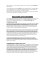
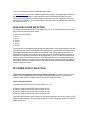
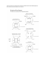
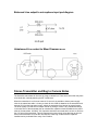
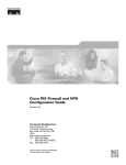
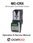
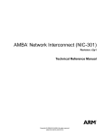
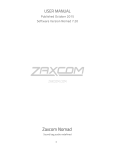
Zaxcom Transmitter Guide
Zaxcom Inc. 230 West Parkway, Unit 9, Pompton Plains, NJ 07444 - 973-835-5000
Document Revision 1.037.00
For Firmware Revision 38 and Higher
This guide assumes the firmware version displayed above is installed. The firmware revision
code is displayed shortly every time the transmitter is turned on.
Important Note for Goldline and Handheld Wireless Transmitters: Only Lithium or
rechargeable NiMH should be used in these models. Any other battery chemistry
(including Alkaline and “Ultra” batteries) will have a substantially reduced run-time
compared to Lithium or rechargeable NiMH cells. This is true for all Zaxcom transmitter
models that accept AA batteries. Never use any battery that is missing insulation on its
body. This can allow a short circuit in the battery compartment causing damage to the
transmitter.
Goldline and Stereoline Power up
Install 2 AA batteries into the transmitter. Press in the battery door and slide the battery door
down to open the compartment. Be sure to install the batteries with the correct polarity.
Damage to the unit may result if the batteries are installed backwards. The Positive and
Negative indicators are printed on the battery contacts inside the unit. The battery next to the
door hinge is positive out and the other battery in negative out. For maximum transmitter time use
Energizer Lithium batteries. This should give a transmitter time of 6-7 hours. On power up the
transmitter will display the version number of the software and then will go to a mode where one
display LED blinks to indicate the power is on.
The power switch is located on the top of the transmitter. Slide it to the on position to turn on the
unit. The power button “PWR” is used to check the battery level of the transmitter.
In the case of a Stereoline transmitter the power switch is labeled “INT” (internal) and “EXT”
(external), if the unit has AA batteries inside, use the Ext position for power off. If external power
is present use the Internal position for power off when AA batteries are not present. If both power
sources are present the unit will not power off until one of them is removed.
Handheld Mic Power up
Operation of the Handheld Mic (or Stick Mic) is similar to the Goldline transmitter: To access the
battery compartment and the user interface, unscrew and remove the bottom of the microphone.
Insert two Lithium or NiMH AA batteries into the unit. The negative contact should be inserted
first into the microphone; the positive contacts of the batteries should be closest to the antenna
side of the unit. The power switch and power indicator LED are both located next to the antenna
on the outside of the unit.
Since the electronics are exposed when the base of the unit is off, make sure to use clean, dry
hands otherwise the transmitter may be damaged or the performance of the transmitter may be
degraded.
Spy II Transmitter Power up
The compatible battery type is a rechargeable cell phone Lithium Ion SNN5705B. To install take
the narrow end of battery, with the contacts facing down and to the left, and place it into the
transmitter at a 45 degree angle. The battery should then be lowered into the transmitter with
light pressure towards where the contacts meet until it clicks into place. Battery should go in
easily and never be forced.
To remove the battery, hold it with your thumb and forefinger, slide it as far to the left side as
possible, and gently lift out.
On power up the transmitter will display the version number of the software and then will go to a
mode where one display LED blinks to indicate the power is on.
The power switch is located on the top of the transmitter. Slide it to the on position to turn on the
unit. The power button “PWR” is used to check the battery level of the transmitter.
Transmitter Menu System
The user interface for the transmitter consists of 3 LED digits and 4 buttons:
PWR = Power on/off: Hold for 3 seconds to turn the transmitter on or off. (Slimeline Only)
FNCT = Function/menu page select: Press to cycle through each menu page.
UP/INC = Increment the current parameter selected by the FNCT key.
DOWN/DEC = Decrement the current parameter selected by the FNCT key.
The transmitter has a few menu pages that allow the user to change various settings. Note that
the transmitter will store the user's settings in FLASH ROM when power is removed. There is no
secondary memory battery so the settings will always remain secure without any power. The
available menu pages are summarized below.
PACIFIER PAGE:
AUDIO GAIN PAGE:
CHANNEL SELECT PAGE:
LOCK MODE PAGE:
Indicates the unit is on by flashing a single LED.
Allows user to change the mic preamp gain.
Selects channel center frequency.
Staying here locks out key presses. PWR+INC exits lock mode.
The last three menu pages are infrequently used special functions. In order to get to those pages
the FNCT key must be held while powering up the transmitter. To exit this special menu system,
press the power key shortly or cycle power.
ID CODE #0 SELECT PAGE:
ID CODE #1 SELECT PAGE:
FORMAT SELECT PAGE:
HIGH-PASS FILTER PAGE:
RF POWER OUTPUT PAGE:
Changes the security0 code (normally should be set to zero)
Changes the security1 code (normally should be set to zero)
Changes the transmission data format (normally zero)
Changes the cutoff frequency of the high-pass filter
Changes RF output power. (version 048/148 or lower)
Repeatedly press the FNCT key to cycle through the following menu pages.
PACIFIER PAGE
At power-up the transmitter will enter the home pacifier page. The UP and DOWN keys have no
function in this page. In this page a single LED will blink periodically to indicate that the
transmitter is on. When used in normal conditions the transmitter should be placed in LOCK
mode in which no LEDs are lit and the keys have no function. Pressing the power key for a short
time will always bring the user to this page (unless in LOCK mode in which case the user must
press PWR+UP).
AUDIO GAIN PAGE(s)
This page is indicated by the letter 'G' followed by a two-digit number. (Stereo transmitters have
two gain pages for the left and right audio channel indicated by “L” and “r”). The two-digit number
indicates the gain setting of the mic preamp. This gain setting code will disappear after 1 second
and the display will be converted into an audio level meter. When audio is applied to the
microphone input the LEDs display the audio level. The audio level is referenced in 6 dB
increments as shown on silkscreen above the display. The mic preamp gain may be adjusted in
this page by pressing the INC or DEC keys repeatedly. Unless a microphone is connected to the
unit's input the display will go blank but stay in the gain setting mode. If a significant audio signal
is present, the display will meter the signal level horizontally from left to right, from -18 dB to +12
dB. As you speak into the microphone, you can raise and lower the gain with the UP key and the
DOWN key. The gain is adjusted in increments of 2 dB.
One of the key features of the unit is a digitally controlled analog limiter located before the A/D
converter. This means that the digital signal processor can automatically turn down the mic
preamp gain when excessive audio is detected to prevent clipping of the A/D converter. This
compressor/limiter will engage before signal exceeds the digital capabilities of the signal path.
This is indicated when 3 horizontal LEDs light simultaneously. The compressor/limiter will
activate at about 10 dB from clipping (digital clipping would occur at +20 dB). The gain level
should be set low enough so the compressor/limiter does not engage even when the talent
is shouting. This can be accomplished by allowing the talent to shout while decreasing the gain
until the unit stops producing a limiting warning. Since actors tend to shout even louder when the
cameras are rolling, it is a good idea to decrease the gain a few dB more to allow some
headroom. This gain setting will remain intact even when the battery is removed.
If the transmitter is a Stereoline it is normal for the gain settings on the left and right sides to be
different. This is due to the differences in component tolerance between the 2 audio channels.
The numbers can be off as much as 10 digits and still be correct.
CHANNEL SELECT PAGE
This page will display the current channel code. To change channels, press the UP and DOWN
keys. The channel code is displayed as the last 3 digits of the true frequency. For example, if the
unit is transmitting at a frequency of 532.1 MHz the channel code will be displayed as "321". The
transmitting frequency is adjusted in 100 kHz (0.1 MHz) increments.
Changing the channel will prevent the transmitter from transmitting for 1 second. This allows the
user to change channels without transmitting over every single channel that is encountered while
obtaining the desired destination channel frequency. If the channel is changed quickly the
transmitter will remain quiet until the desired channel has been selected.
When operating multiple transmitters in the same location it is recommended that a channel
spacing of at least 1 MHz be maintained. This is achieved with ten steps of increment or
decrement in the CHANNEL SELECT page from whatever the adjacent channel is. The
transmitters allow a channel frequency to be chosen anywhere in a 30 MHz range. Utilizing a
large channel spread between transmitters will aid reception. Maintaining a distance of 20 feet or
more between any transmitter and receiver will also aid in reception when many transmitters are
in use at the same time. This prevents any transmitters from de-sensing the receiver.
Channel plan programs used to prevent intermod problems are not needed when using the
Zaxcom Digital Wireless system. However, if regular FM mics are being used close to the
Zaxcom system then the user must choose channels wisely to prevent intermod. When two FM
transmitters come close to each other they can transmit interference on adjacent channels. Since
this interference is transmitted into the air there is no way for the Zaxcom receiver to reject this
interference. The Zaxcom transmitters do not suffer from this problem.
LOCK MODE ACTIVATION PAGE
The purpose of the LOCK MODE is to prevent users from pressing buttons accidentally. LOCK
mode is a safety feature that disables all button functions except the ability to unlock. The display
will show 'LOC'. If left in the LOCK MODE page for a few seconds, the unit will lock when the
display goes dark. If you scan past the LOC display to the next menu item, the LOCK MODE will
not be engaged.
To unlock the transmitter, hold the POWER key and then press the UP key. The display will show
'UNL' indicating that the unit is unlocked. Upon release of the buttons, the single flashing LED
returns, showing that the unit is operating in the home pacifier page.
If for some reason, you forget this procedure, you can always just cycle power on the transmitter.
Disconnecting the battery will also automatically unlock the unit.
SPECIALIZED FUNCTIONS MENU
To access the SPECIALIZED FUNCTIONS menu, make sure the transmitter is powered off. Hold
down the FNCT key while powering up with unit. The display will read 'ID' when the unit has
powered up. This indicates that the transmitter is in the ID CODE SELECTION page.
ID CODE SELECTION
The transmitter has two user selectable Security Identification Codes called ID0 and ID1. Both ID
codes should be set to 000 to allow normal, un-coded operation. The user may enter two 3digit security ID codes which internally are concatenated to form one 6-digit code. If the exact
same codes are not present in the receiver, the receiver will not be able to decode any audio
from this transmitter. The two ID codes are merely the upper and lower half of a single binary
security key. This key is used to scramble all transmitted data.
Unless a receiver has the same security key, it will not be able to make any use of the transmitted
data. This security mode is useful in a corporate board room setting where sensitive information
must not be made public. If an FM transmitter were to be used in this situation the transmitted
audio could be heard over 2 miles away by using a cheap scanner and a high gain antenna. If an
un-coded Zaxcom transmitter were to be used, the unintended listener would not be able to use a
scanner to receive the audio, but he could receive the audio if he had a Zaxcom receiver. By
coding the transmitted audio with a security key the unintended listener would have to check
each of 8 million codes before he could receive any audio.
If a receiver has been programmed with a security code, it will still receive an un-coded
transmitter (both ID#0 and ID#1 codes set to 000). Since this receiver has to check for two
possible code situations a slight performance penalty may occur during long-range reception.
Therefore it is recommended that the transmitter and receiver codes both be set to 000,000 when
high security is not needed.
TRANSMISSION FORMAT SELECTION
The display will show "FoX" where X is the number 0 ,1 or 2. If this item is not set correctly the
receiver will not be able to receive any audio from this transmitter. This item allows the user
to choose between US mode and European mode. This user selection will not take effect
until the unit has been powered down and restarted. The US mode (mode 0) transmits a
signal that occupies a bandwidth of 200 kHz. This is legal in the US and several other countries.
This mode provides the best audio quality. The European mode (mode 1) is designed to occupy
a 140 kHz bandwidth. This mode will allow a greater transmitter range and will allow more
transmitters to operate simultaneously than the US mode. Check local legal requirements to
determine which mode is allowed in the country you are operating in. In the future, there will be
more modes to choose from which will increase range and audio quality even further.
If the TX is a Stereoline unit Fo2 will indicate stereo mode.
Visit www.zaxcom.com for future software additions and updates. By upgrading the software in
the transmitter and receiver the range and feature set will dramatically increase over time.
Zaxcom has a reputation for constantly adding new features and user suggestions during the
entire lifetime of a product. This ensures that your wireless system will perform better and better
the longer you own it.
HIGH-PASS FILTER SELECTION
The display will show 'HPx' where x is a number from 0 to 6. This indicates different high-pass
filter cutoff frequencies as shown below.
0: 30 Hz (no audio filtering)
1: 40 Hz
2: 64 Hz
3: 102 Hz
4: 164 Hz
5: 262 Hz
6: 419 Hz
These frequencies are logarithmically spaced and the filters are implemented digitally. Note that
since the high-pass filter is implemented in the digital domain, the automatic compressor/limiter
may engage even when the user hears no substantial audio. The purpose of the limiter is to
prevent the mic preamp from over-driving the A/D converter. Therefore the limiter operates on
audio before it has been processed by the high-pass filter. If there is a massive amount of low
frequency audio content being filtered out by the high pass filter (such as wind noise) the user
may hear the effects of the limiter without hearing the audio that caused the limiter to engage. If
this problem occurs then the gain is set too high. Reduce the mic preamp gain well below that
which will trigger the limiter.
RF POWER OUTPUT SELECTION
This function is inoperative from version 149/049 and higher. The power output is fixed at
65mW. The new hardware design uses higher battery power when the RF output power is
reduced making 65mW the optimum power level for this hardware version.
Version 148/048 and below
The display will show 'PrX' where X is a number from 1 to 3.
A setting of 0 will produce an RF output of about 3 mW
A setting of 1 will produce an RF output of about 20 mW
A setting of 2 will produce an RF output of about 50 mW
A setting of 3 will produce an RF output of about 90 mW
This mode may be used to extend battery life or reduce interference with nearby receivers or RF
sensitive audio equipment. These settings as well as all other settings are saved even when the
battery is removed.
Hardware and Accessories
Antenna
The transmitter uses a gold plated SSMA connector. Included is an antenna cut to the correct
length for your transmitter's specific frequency. The connector is a simple coaxial thread-on. It is
a good idea to periodically check that the connector is securely mounted.
Wire Clip (Goldline and Stereoline)
The Goldline and Stereoline transmitters use a wire belt clip. Attach the clip to the transmitter by
inserting the clip into the 2 holes in the sides of the transmitter.
Cell Phone Lithium Ion SNN5705B (Spy II only)
The Spy II system comes standard with one battery and charger. Additional batteries may be
purchased from anywhere cell phone accessories are sold.
MICROPHONES AND OTHER AUDIO INPUT
Microphone selection can be a little tricky. This is a current list of microphones that the Goldline,
Stereoline and Spy transmitters will operate with.
Sanken COS-11
Sennheiser MKE2 Platinum
Countryman B6
Countryman EMW
DPA 4063
Shure WL50
(Do not use the Gold model)
(ask for the 3.3v model)
Other microphones will be added as soon as verification of 3.3v power performance and RF
interference susceptibility can be checked.
The Zaxcom transmitter has a balanced microphone input accessed through a 4 pin Micro-Lemo
connector. You can use a balanced dynamic microphone or a powered lavaliere. Zaxcom
recommends 3-wire lavalieres that utilize a separate ground pin, audio pin and power pin.
If it is necessary to transmit a line level input, an inline pad will be required on the standard
dynamic microphone input cable (3 pin XLR to 4 pin Micro-Lemo).
48 Volt phantom microphone powering will require an external 48 Volt power supply when using
the Goldline, SPY II or Slimline transmitters. The MMT transmitter is the only transmitter with a
built in 48V supply.
Warning
Deneke 48 V power supplies will blow up the mic preamp of the transmitter
if they are connected to the transmitter when their power is switched on. The Deneke puts
a 48V spike into the transmitter when this happens. Please avoid this unit if at all possible.
When wiring a microphone it is necessary to connect the shield of the cable to the shell of the
Lemo connector as well as to the ground of the microphone. Separating some ground strands
and pressing them between the shell of the connector and the internal cable strain relief can
accomplish this. To avoid RF interference from getting into the audio it will also be necessary to
add a 200pF capacitor between Mic+ and Ground pins. A 0402 surface mount capacitor
(supplied with all connectors) should be fitted directly between the pins in the connector. If RF
noise is present in the audio then this connection procedure has not been followed properly or
there is a bad connection inside the mic connector.
Balanced Line output to microphone input pad diagram
Unbalanced Line output to Mixer Diagram (Wendt)
Stereo Transmitter and Bag to Camera Notes
The Stereoline transmitter will find use as a bag to camera link. There are 2 issues that may have
to be dealt with, external powering and RF interference.
When the transmitter is run from an external 12v source it is possible to induce power supply
noise in the transmitter audio. It is easy to check for this. With AA batteries in the transmitter and
external 12V from the bag power supply, switch the transmitter from internal to external power.
The audio quality from the receiver output should not change. If there is any substantial change
in the noise floor of the transmitter then an external filter capacitor should be added to the power
cable of the transmitter. A 3300uF 16V Capacitor should be connected within an inch or two from
the 12V input of the transmitter. This will suppress any power supply noise that can get into the
audio of the transmitter as will as the other devices in the bag. A cable with the Capacitor
installed can be purchased from many of our Dealers.
RF interference to other receivers in the sound bag can be a tricky issue. If our transmitter is
within a foot of other wireless receivers the effective range of the other receivers may be affected.
If the RF level meter on the receivers indicates that RF is present then corrective measures
should be taken.
There should be at least 50 MHz frequency separation and 1 foot of physical space between the
stereo transmitter and receivers in the same bag. If the units are closer than this problems may
occur.
To correct an interference problem a Zaxcom filtered antenna model FDP1 can be ordered. This
is a small Dipole antenna with a very high Q tuned filter that can be clipped to the side of the bag
or to the strap. It limits the RF output from the transmitter to a 40 MHz range. This should clean
up any interference to receivers that are operating outside the 40 MHz range of the filter. The
filter must be ordered in a specific frequency block.
As a side note this filter works great to clean up video assist transmitters that can also interfere
with wireless microphones.
Zaxcom Remote Control Quick Guide
1.0
This is a quick guide to using the Zaxcom Remote Control software on the Compaq iPaq.
This document assumes that you are already familiar with using the Zaxcom digital
wireless receiver and digital wireless transmitter. The iPaq software generates audio
tones necessary to alter the settings on the transmitter. It provides a large user-friendly
touch screen that lets the user easily and quickly alter transmitter settings. The remote
control features will not work unless you are using version 25 or greater of the digital
transmitter firmware. The version is briefly displayed when the transmitter is turned on.
2.0
To start the program, use the stylus and press the Start system prompt on the top left
line of the iPaq. The menu shows a list of programs that includes “ZAX Remote” with an
icon next to it similar to an antenna. Click on this line to start the program. On the screen
you will see six buttons. These are: Decrease Gain, Increase Gain, Special Functions,
Utility Functions, Channel, and Exit.
2.1
2.2
The Gain buttons immediately decrease or increase the audio gain in 2dB steps
on the transmitter. Press the button to listen to the tones generated. When using
the iPaq note that the touch screen button changes color when pressed, but
does not actually send the tones until it is released. For best results, place the
microphone from the transmitter within six inches of the iPaq speaker, which is
located near the bottom of the unit on most iPaqs. The transmitter will flash its
LEDs on for 1/2 second when a valid command has been received. The volume
setting on the iPaq should be one tick below its loudest setting. To easily get to
the volume function, press the “Q” button on the iPaq quick keys and then select
volume.
The Channel (Frequency) button brings up an entry screen where you can
change the channel of the transmitter. The last transmitted channel setting is
displayed at the top of the screen. It is very important to make sure that the
setting on the receiver matches this transmitter setting! Warning! No audio will
be received if the transmitter and the receiver's channels do not match. To
completely enter a channel, you must enter four digits. Observe how the display
changes as each digit is pressed. When the SEND button is pressed the remote
control software will save this channel for future use. If the SEND not pressed,
2.3
2.4
this value is discarded when you leave this screen. Pressing the Clear button will
enter “000.0” on this display. Use this if you are uncomfortable viewing the
shifting display when changing the channel values. To return to the previous
screen, press the Prev Screen button.
The Utility Menu has six buttons: TX power, Security, Hi Pass filter, Audio Gain
Presets, and Previous Screen.
2.3.1 The TX Power button allows you to change the transmitted RF output
power setting from 25mW, 50mW or 100mW. The last transmitted power
setting is displayed at the top of the screen. These keys take immediate
action.
2.3.2 The Hi Pass Filter screen allows you to alter the transmitter's internal
audio high pass filter settings from 30Hz, 40Hz, 65Hz, 100Hz, 160Hz,
and 260Hz. These keys take immediate action when pressed. The last
transmitted filter setting is not saved.
2.3.3 Security setting is composed of two parts: Id0 and Id1. When these fields
are set to 000 and 000 on a transmitter, any receiver can get the audio
from a transmitter with just a matching channel. If a transmitter has
values other than Id1 = 000, and Id2 = 000, only a receiver with matching
ID codes will receive the audio from the transmitter. The ID settings will
not be saved until the SEND button is pressed, otherwise, they will be
discarded.
2.3.4 The Audio Gain Presets is different from the Main Menu gain. In the Main
Menu, the commands are sent to change the audio gain up or down in
2dB steps each time a button is pressed. In the Audio Gain Menu, the
gain is set to a fixed value. The current gain value is displayed at the top
left of this screen. The current preset gain values are displayed to the
right of the preset buttons. The current gain is assigned to a preset, after
the desired gain has been selected using the increase and decrease
gain buttons, by pressing the desired preset. This function provides a
means of setting the transmitter gain to a fixed value without having to
repeatedly press the increase or decrease gain buttons.
2.3.5 The Send All button displays the current software version (1.22) and the
four settings that are saved on the iPaq. These are Channel, TX Power,
Security, and Audio Gain. If the SEND ALL button is pressed, all four
values will be sent.
The Special Functions menu has four items: Standby/On, Test Tone On, and
Test Tone Off.
2.4.1 The Standby/On button is used to turn off the transmitter's RF circuitry.
This reduces the transmitter power consumption by 50%.
2.4.2 The Test Tone On button turns on a 2kHz audio reference tone from the
transmitter. There is no time out on this tone. The Tone Off command
must explicitly turn it off or you must cycle the transmitter power.
2.4.3 The Test Tone Off button turns off the 2kHz audio reference tone from
the transmitter.
Supplemental Documentation for Clothing Noise Reduction Software
A transmitter may be supplied with a special version of software that implements an innovative
Clothing Noise Reduction (or CNR) algorithm. Such a transmitter contains a 2 channel (stereo)
audio section and is capable of transmitting 1 or 2 channels to the receiver. The receiver that is
paired with a transmitter with clothing noise reduction does not need to have any special software
installed.
The CNR algorithm allows the transmitter to choose between its two microphones; when audio
from one microphone is noisy or unusually loud the transmitter cross-fades to the other
microphone. The transmitter only transmits one channel at any given time. This greatly reduces
the occurrence of clothing noise in the final transmitted signal.
A transmitter with the CNR option has a two extra menu pages that are not found in a normal
mono or stereo transmitter.
“CLO” page
In the main menu there is a threshold adjust page labeled “CLO”. The value of the CLO threshold
can be adjusted from 00 to 99. Where a setting of 00 results in a very sensitive decision point at
which the CNR algorithm decides to switch microphones. A CLO setting of 99 reduces the
tendency of the CNR algorithm to switch to another microphone. If the transmitter is switching
back and forth between microphones too often, adjust the CLO setting to a higher number. A
setting of 99 is a good place to start.
“BAx” page
In the extended menu pages there is a balance control labeled “BAx” where x is a number from 0
to 8 and 4 is the center (note: hold the FUNC key during power up to get to the extended menu
pages) . This setting allows the user to balance out any differences in gain that might occur
between a pair of microphones. All microphones have a slightly different gain then one another
and the CNR algorithm requires an equal level between microphones to operate effectively. The
balance setting allows the user to pan between the two microphones until they are approximately
the same audio level. If the CNR algorithm seems to be favoring one microphone over the other,
then adjust the balance so the favored microphone has less gain.
Transmission Formats
A transmitter with the CNR option is merely a stereo transmitter with special software installed. In
the extended menu pages the user may choose between 3 transmission formats (Fo0, Fo1, Fo2):
Format 0 (US): This setting transmits in wideband CNR mono mode This mode is recommended
for US customers or other countries where a 200kHz channel bandwidth is legal.
Format 1 (European): This setting transmits in narrowband (less than 160kHz) CNR mono
mode. This setting is recommended for European customers where the channel bandwidth
requirements are stricter.
Format 2 (US Stereo): This mode transmits a 200kHz bandwidth signal that is the same width as
Format 0, but the data that is sent is 2 discreet audio channels. In this mode CNR is disabled and
the audio from each microphone is transmitted as a separate audio channel in a single 200 kHz
wide digital data stream. This format behaves the same as a normal stereo transmitter without
CNR.
Note that the receiver must be told which format setting the transmitter is set up for. Also,
remember that the format menu setting does not take effect until the unit has been powered off
and powered back on again.
The standard Zaxcom receiver operates as both a stereo and a mono receiver. The only
difference between a stereo and a mono receiver is a jumper setting inside the unit which
determines how the headphone monitor circuit operates. It is not necessary to have this jumper
setting setup correctly to use the stereo mic/line output of the receiver.
Transmitter Software Revision History
05-21-02 rom915: beta stereo version for law enforcement applications
06-04-02 rom19 : new LED sw
06-15-02 rom20 : added optional standby mode for power off/on
06-19-02 rom21 : internal changes
07-10-02 rom22 : added battery curve tables for MMT and Goldline
added European Enumerated channel mode
07-12-02 rom922: European mode for BBC testing
07-18-02 rom923: EU: changed format #1 to new audio format
08-19-02 rom023: US: shipped new US audio format
08-20-02 rom024: added remote control sw
swapped menus for ID0, ID1 for better intuitiveness
09-26-02 rom025: added "ooo" remote confirmation to LOCK screen
rom025 added 2khz tone generation (remote control only)
09-04-02 rom025 internal changes
09-11-02 rom026 internal changes
10-25-02 romE26 (no sw change) compiled European channel mode versions
11-08-02 romB26 extended gain table for special unit
12-11-02 rom027 extended gain table for all units
02-06-03 rom029 added lower power setting (P=0) = 3mW RF output
03-29-03 rom930 (for stereo hardware) made changes for clothing noise alg
brought in balance adjust from stereo sw
04-15-03 rom831 changed STICK-MIC gain settings
06-26-03 rom832 switched inc and dec keys for new STICK MIC pcbs
07-28-03 rom033 CHANGED EU FORMAT Major stereo upgrade (added format#2=stereo)
Incompatible with RXer rom30 and lower software (EU fmt)
stereo: added LEFT and RITE gain settings in menu and remote control
fixed power bug in init concerning slimline powering down immediately
09-22-03 rom34 tweaked clothing noise, balance, gatelp display=C00..C99
10-09-03 rom35 fixed EU channel memory bug for stick mic from Rom834
replaced LOC menu page
Block 31 units automatically engage EU channel mode (TV ch68)
increased LOCK timeout from 4 to 6 seconds
10-09-03 r36 <<<<<< use this sw with rom 243 or greater >>>>>>>>>>>
reset automatic EU mode so it is triggered by
by TVchannelMIN=79 (860.0mhz) (blk 33 unit)
(TVMAX should be set to 80 => max ch will be restricted to EU limits)
note: ch1=854.9mhz .. ch14=861.75mhz
EU allows: 863.1 - 864.9mhz + the ch1..14 (1.8mhz of ch79)
(RXer still needs special rom for a blk33 unit)
10-15-03 r37 added RESET audio ADC to fix DC offset intermittent
VERSION
equ $37 ; (last 2 digits of rom number)
prefix code: 0xx=normal mono txer version
1xx=US stereo (stereo audio board installed)
5xx=stereo + clothing noise reduction (stereo audio board installed)
8xx=stick mic