1
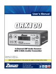
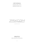
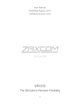
USER MANUAL
Published July 2015
Software Version 1.0
Zaxcom RX12 / QRX212 Module
Streamlined Reception
1
KNOW YOUR RX12 ........................................................................................................................................ 4
FRONT PANEL ............................................................................................................................................................ 4
RIGHT SIDE ................................................................................................................................................................ 5
LEFT SIDE .................................................................................................................................................................. 6
REAR ........................................................................................................................................................................ 6
INSERTING THE QRX212 MODULES .............................................................................................................................. 7
HOME SCREEN EXPLAINED ........................................................................................................................................... 8
SYSTEM MENU .............................................................................................................................................. 9
RECEIVER CONFIGURE MENU ........................................................................................................................ 9
RX MODE ................................................................................................................................................................. 9
Mode .................................................................................................................................................................. 9
Power ................................................................................................................................................................. 9
FREQUENCY ............................................................................................................................................................... 9
TRANSMITTER GAIN .................................................................................................................................................... 9
UNIT CODE .............................................................................................................................................................. 10
OUTPUT TYPE .......................................................................................................................................................... 10
AES MODE.............................................................................................................................................................. 10
TONE ...................................................................................................................................................................... 10
CENTER FREQUENCY SET ..............................................................................................................................10
SCAN MENU.................................................................................................................................................11
CENTER FREQUENCY .................................................................................................................................................. 11
MARKER ................................................................................................................................................................. 11
FREQUENCY LIST / AUTO-PICK ......................................................................................................................12
HOW TO USE AUTO-PICK ........................................................................................................................................... 12
ENCRYPTION ................................................................................................................................................12
SETTINGS MENU ..........................................................................................................................................13
FAN SPEED .............................................................................................................................................................. 13
LCD BRIGHTNESS ..................................................................................................................................................... 13
QRX PROGRAM ....................................................................................................................................................... 13
How to update the software for the QRX212 modules ................................................................................... 13
RECALL FACTORY DEFAULTS ....................................................................................................................................... 14
ZAXNET FREQUENCY CONTROL ................................................................................................................................... 14
SERIAL PORT MODE .................................................................................................................................................. 14
How to send remote commands ..................................................................................................................... 14
ADVANCED SET UP .................................................................................................................................................... 14
Burn Boot loader .............................................................................................................................................. 14
Debug Bits ........................................................................................................................................................ 14
Allow Logging ................................................................................................................................................... 14
Log Screen ........................................................................................................................................................ 14
2
RX12 CONNECTOR ASSIGNMENTS ................................................................................................................15
SINGLE ANALOG CHANNEL OUT OF ONE TA5................................................................................................................. 15
TWO ANALOG CHANNELS OUT OF ONE TA5 .................................................................................................................. 15
AES DIGITAL OUT OF TA5 .......................................................................................................................................... 15
DC POWER IN (HIROSE HR10A-7P 4 PIN MALE) .......................................................................................................... 15
SERIAL CONNECTOR (USB RS-485) ............................................................................................................................ 16
Nomad or QRX ................................................................................................................................................. 16
IFB200 or TRX900 Camera Link ........................................................................................................................ 16
UPDATING THE RX12 FIRMWARE..................................................................................................................17
PRODUCT SUPPORT .....................................................................................................................................18
ZAXCOM RX12 SPECIFICATIONS ....................................................................................................................19
ZAXCOM WARRANTY POLICY AND LIMITATIONS...........................................................................................20
3
Zaxcom RX12
Front
Know Your RX12
Front Panel
1
2
3
6
1.
2.
3.
4.
5.
6.
7.
5
7
UHF Antenna A
Numeric keypad
Back Key
Daylight Readable Color LCD Screen
UHF Antenna B
Enter Key
Menu Encoder Knob - Press the menu knob to access the RX12 menu. Rotate and press to adjust the
menu perimeters.
Navigation shortcut from the home screen:
•
•
4
Pressing the star key will advance to the receiver configuration menu
Pressing the pound key will advance to the scan menu.
4
Zaxcom RX12
Right Side
Right Side
1
2
5
3
4
6
7
1. UHF Antenna B RF Loop through RF Out - The RF out is after the 35MHz filter and has 3dB of gain.
2. External Power Connector (Hirose-4F) Voltage range 10 to 18 VDC
3. Audio Outputs for Modules 1 - 6 (TA-5M)
Each output can be configured to output analog or AES audio.
Please note when outputting more than two signals the modules will need to output an AES signal.
4. QRX212 Module Position 6
5. Power Switch
6. Serial Communication Port
The Serial port is used to connect the RX12 to a Nomad, IFB200, TRX900CL or QRX with QIFB.
When connected the RX12 can send remote frequency and gain commands to the TRX transmitter.
7. QRX212 Module Position 5
5
Zaxcom RX12
Left Side
1.
2.
3.
4.
5.
Left Side / Rear
1
2
4
5
3
QRX212 Module Position 2
QRX212 Module Position 1
UHF Antenna B Loop through RF Out – The RF out is after the 35MHz filter and has 3dB of gain.
QRX212 Module Position 3
QRX212 Module Position 4
Rear
1
1. Vent Fan
6
Zaxcom RX12
Inserting the QRX212 Modules
Inserting the QRX212 Modules
Rear view of the QRX212 Module
QRX212 Modules slide into the RX12 with the arrow pointing to
the top of the RX12
Fastening screws
• With the arrow on the QRX212 module pointing to the top of the RX12 gently insert the QRX212 into the
RX12 frame until you feel the module mate with the RX12.
• Insert the supplied screw through RX12 into the QRX212 to hold the module in place. Caution: do not over
tighten the screw. The screws for the top RX212 modules will go through the top of the RX12 and the
screws for the bottom modules will go through the bottom of the RX12.
7
Zaxcom RX12
Home Screen
Home Screen Explained
The home screen is divided into six sectors, one sector for each QRX 212module. Each sector will display the
following information:
• Frequency - The current selected frequency will be displayed for each receiver. If the module is in dual
mode both frequencies will be displayed. The A frequency will be on the left and the B receiver will be on
the right. If the frequency is highlighted in red that means the selected frequency is outside the 35MHz
filter. Keep in mind while frequencies outside the range of the 35MHz may still work though performance
will be less than optimal.
• Battery level - A battery indicator will display the approximate battery level for each transmitter. A
fully charged battery will display green and then turn red as the battery depletes its charge. The battery
icon will start blinking when the battery has roughly 15 to 30 minutes of charge left. Please note that
when the battery is low the transmitter may not go into record.
• Transport status -The transport status of the TRX transmitter’s onboard recorder will be indicated just
above the RF signal strength meter:
• STOP – Recording / Playback is stopped
• REC – TRX is recording
• PLAY – The TRX is playing back
• RF Signal Strength - Each module has two RF meters, one for each receiver. The meters show the
amount of RF signal being received. The signal level is visually displayed in the ramp shaped RF meter icon.
As the shading increases from the left to the right the more signal is present. If the icon is shaded red that
means the receiver is seeing unwanted RF from a source other than from a TRX transmitter. If the icon is
green the RF is being received from a TRX transmitter. Within the icon the actual signal strength, in
decibels, is displayed numerically.
• Audio meter - Each module will display audio meter(s) for each signal received. If the module is set to
single mode one large meter will be shown. If the module is set to dual mode two large meters will be
shown. If the module is receiving a signal from a stereo transmitter the large meter will be split in half into
two smaller meters, representing the left and right audio of the transmitter. The meters will show the
audio modulation in dBFS. Within each meter the signal will be represented in green, yellow and red
showing the levels, there is also a peak hold indicator. If a meter has a white X through it that is showing
that the receiver is not receiving a valid signal.
• Save Indicator - A pixel on bottom of screen that moves right to left indicates that the RX12 is saving a
parameter setting to its memory. If the RX12 is powered down while the pixel is moving the settings will
not be saved and could possibly corrupt the setting memory.
8
Zaxcom RX12
System Menu
System Menu
To access the system menu press the MENU encoder knob.
Receiver Configure Menu
The receiver configure menu is where each of the 6 QRX212 receiver modules are be set up from. To access the
receiver configure menu press the star key from the home screen. Or select it from the system menu.
Once in the receiver configure menu individual receiver modules can be accessed by pressing the corresponding
number key on the numeric keyboard.
In each receiver configuration menu the status
of each transmitter will be shown. This is the
same configuration that is in the home screen.
Included are the frequency, battery level, signal
strength and audio levels.
RX Mode
From the RX mode menu each individual QRX212 module can be powered on and off and set to single or dual
mode.
Mode
• Single – The QRX212 module is set to receive a single TRX transmitter.
• Dual – The QRX212 module is set to receive signal from two TRX transmitters
Power
This is used to toggle on and off the power to the QRX212 module. Turning power off will shut off the
individual module and will conserve power.
Frequency
This displays the current frequency that the QRX212 is set to and is where the frequency for the A and B receiver
can manually be set from.
To set the frequency highlight the frequency of the receiver you would like to change and rotate the menu
encoder knob, or press the desired frequency on the numeric keypad.
Transmitter Gain
If the RX12 is connected to a Nomad, IFB200, TRX900CL or a QRX with QIFB, the gain for each TRX
transmitters can be adjusted from here and will be remotely sent to the TRX transmitters via the serial port
connection.
9
Zaxcom RX12
System Menu
Unit Code
This is where the ZaxNet unit code for each module is set. The unit code on each QRX212 receiver must
match the unit code set in the TRX transmitter so that remote frequency and gain commands can be sent to
the proper transmitter. Each receiver and transmitter pair must have its own unique unit code. The unit code
number can be set to any number between 1 and 99.
Output Type
The output type sets what audio signal the individual QRX212 module will output via the TA5 connector. Each
module can be set to output the audio as either an analog signal or an AES signal.
AES Mode
There are two AES output pairs per QRX212 module. When receiving two mono transmitter signals on a
single QRX212 module the two audio channels will appear on one AES pair by choosing the AES swapped
mode
Tone
Each QRX212 module has its own tone oscillator. Turning tone on will output tone from the TA5 connector
at -20dBFS allowing for the levels to be calibrated at the mixer or recorder.
Center Frequency Set
The RX12 has a 35MHz tracking front end filter that eliminates unwanted stray RF which can desensitize the
receiver and result in poor performance.
The center frequency is the middle frequency of the 35MHz window.
After deciding on the 35MHz operating range the center frequency should be set to the middle of that range.
Therefore the best performance of the RX12 will be frequencies chosen 17.5MHz above and 17.5MHz below
the center frequency. Please note that this is a global setting for all QRX212 modules meaning that that the
35MHz window will be the same for all modules.
To adjust the center filter rotate the menu encoder knob to the desired frequency, or manually enter the
desired frequency using the numeric keypad.
10
Zaxcom RX12
System Menu
Scan Menu
80 dB
70 dB
60 dB
50 dB
40 dB
From the scan menu is where the RX12 can search the spectrum to determine what RF is present. This will aid
in finding a clear operating frequencies. After a scan the RF that is present will be represented in the graph by
a series of vertical lines extending from the baseline up, the higher line the stronger the RF signal is.
The horizontal lines show the strength of the signal in decibels. Any stray RF below 40dB shouldn’t have too
much effect on the performance.
The yellow area shows the 35MHz window of the filter.
The colored vertical lines will show the frequencies that that the QRX212 modules are currently set to.
To initiate a scan press the star key. After scanning the current 35MHz window the filter can be repositioned
by moving the center frequency and additional scans can be performed to show more of the spectrum; the
RX12 will remember the previous scans and add the new scan to those.
When in the scan menu pressing the number 1 key will zoom out showing more of the scanned spectrum and
pressing the number 2 key will zoom in magnifying the scanned spectrum.
After the scan is completed frequencies can be chosen and set manually or Auto-Pick can be used which
allows the RX12 to determine the frequencies.
Center frequency
The center frequency is the frequency that is in the middle of 35MHz filter. The filter extends 17.5MHz above
and 17.5MHz below the center frequency. Adjusting the center frequency will physically move the location of
the filter. To adjust the filter rotate the menu encoder knob or enter the desired frequency on the numeric
keypad.
Marker
The marker is for visual identification to examine a specific frequency within the scan. To adjust the marker
rotate the menu encoder knob or manually enter the desired frequency on the numeric keypad.
11
Zaxcom RX12
System Menu
Frequency List / Auto-Pick
This page displays the current chosen frequency of each receiver module. If a module is set to dual mode both
frequencies will be displayed. From this page frequencies can be selected so Auto-Pick can change the
frequency of any receiver(s).
How to use Auto-Pick
Select a receiver by rotating the menu encoder knob.
Press the encoder knob to select the receiver. That will put a
green check mark to the right of the frequency that will be
changed.
3. After all the desired receivers are selected, press the star key to
let the RX12 choose a frequency with the cleanest scan for each
receiver.
4. Press the # Key to uncheck the receiver(s).
1.
2.
Encryption
This is where the encryption code of the RX12 is set. If the TRX transmitter that is sending audio has
encryption turned on the RX12 can only listened to it if it has the same matching encryption code entered.
When the codes do not match, all that will be heard is white-noise.
Each individual QRX212 module will share the same encryption code therefore if encryption is turned on all
TRX transmitters will need to have encryption enabled as well.
The encryption code should always be set to 000000 for normal un-encrypted operation.
12
Zaxcom RX12
System Menu
Settings Menu
Fan Speed
The RX12 has an adjustable cooling fan on the bottom of the unit. The fan can be turned off or adjusted from 1
through 10 with 10 being the highest setting.
LCD Brightness
The LCD screen and backlight key board is adjustable; this menu allows for brightness adjustments. The
brightness can be adjusted between 0 and 10 with 10 being the brightest.
QRX Program
This menu will show the status of each QRX212 module and the current software version that the module is
running
How to update the software for the QRX212 modules
1. Insure that a stable power supply is connected to the RX12.
2. Set the frequency on all the receiver modules to the same frequency that the TRX transmitter that is being
3.
4.
5.
6.
7.
8.
9.
10.
11.
12.
used to send the software is set to.
Confirm that the encryption code is set to off on the RX12 and the TRX transmitter.
Go into the QRX program menu on the RX12.
Press the star key, each QRX212 module should then display that it is “WATTING” for software.
Insert the micro SD with the program file (QRX-XXX.BIN) in the programing TRX transmitter.
At the TRX transmitter
• Make sure the TRX has fully charged batteries installed.
• Press and hold the MENU key while powering the TRX ON.
• Verify the allow IFB remote control is set to OFF.
• Go to the send QRX program menu.
• Press the INC key.
• The TRX will indicate that it found the program on the card and has started sending it.
When the program file is being received by the RX12, and the QRX212 modules are receiving the program
file, the sectors will start counting up.
When each module is updated “SUCCESS” will be displayed.
If a module does not receive all of the sectors wait, the TRX will begin resending the software again on its
own, and will continue to transmit until manually stopped.
When all the modules are updated you may stop the TRX transmitter.
Power cycle the RX12 and confirm that each QRX212 module is running the updated software.
13
Zaxcom RX12
System Menu
Recall Factory Defaults
From this menu the RX12 can be reset to the factory default setting.
ZaxNet Frequency Control
When enabled the RX12 will send frequency and gain change commands, via ZaxNet to the corresponding
TRX transmitter when the gain or receiver frequency is changed.
Serial Port Mode
When the ZaxNet frequency control is turned on the RX12 can communicate frequency and gain changes to
the TRX transmitters via the serial port on the RX12. The serial port will need to be plugged into the serial
port of a Nomad with ZaxNet IFB, an IFB200, TRX900CL, or a QRX with the QIFB option. Please note the
Nomad will need to be running software version 7.24 or higher, the IFB200 / TRX900CL will need to be
running software version 1.77 or higher, the QRX will need to be running software version 3.55 or higher.
How to send remote commands
Using an IFB200 or TRX900CL
In the extended menu:
• Set the RS232 MODE to AUDIO INPUT.
• Set the PHASE INVERT CH2 to OFF.
• Set the AUDIO INPUT to ANALOG.
Using an QRX with QIFB
In the extended menu:
• Set the SERIAL PORT MODE to ZAXLAN.
Using a Nomad with ZaxNet IFB
In the mode menu:
• GP REMOTE ROLL needs to be OFF.
In the TRX transmitter (running software version 9.02 or higher)
In the extended menu:
• Set IFB MODE to RX.
• Set the IFB RX FREQ to match the IFB TX FREQ on the IFB / CL / QRX / Nomad.
• Set the group code to match the group code on the IFB / CL / QRX / Nomad.
• Set the unit code matches the unit code on the RX12 receiver configure menu.
Advanced Set up
Burn Boot loader
The boot loader is part of the software that helps boot up RX12. Generally, the boot loader will not need to
update. If the boot loader needs to be updated there will be a note released with the software to do so.
The boot loader software is already contained within the RX12 software.
Debug Bits
The debug bits are a factory diagnostic setting and should stay set to 0.
Allow Logging
Allow logging will turn on the logging feature which will allow the RX12 to log warning and error messages
which then can be used by the factory to diagnose the RX12. The logged messages are displayed on the log
screen. If logging is not turned on, and an error occurs the RX12 will not log the errors.
Log Screen
This is where the RX12 displays the logged errors and warnings.
14
Zaxcom RX12
Pin Configuration
RX12 Connector Assignments
Single Analog Channel out of one TA5
TA5 out on
RX-12
PIN 1
PIN 2
PIN 3
PIN 4
PIN 5
XLR into
Mixer
PIN 1
PIN 2
PIN 3
No Connection
No Connection
Two Analog Channels out of one TA5
TA5 Out on
RX-12
PIN 1
PIN 2
PIN 3
PIN 4
PIN 5
XLR into
Mixer
PIN 1 on both XLRs
PIN 2 - Left
PIN 3 - Left
PIN 2 - Right
PIN 3 - Right
AES Digital out of TA5
Please note while sending digital output, it is necessary that the unit on the other end (recorder, mixer, etc.)
have digital inputs with sample rate convertors, as there is no way to synchronize the output data with the
recorder’s digital input.
TA5 out on
RX-12
PIN 1
PIN 2
PIN 3
PIN 4
PIN 5
Into
Mixer
Ground
AES 1/2
AES 1/2
AES 3/4
AES 3/4
DC power in (Hirose HR10A-7P 4 Pin Male)
DC Power
Source
Negative (Ground)
No Connection
No Connection
Positive
Hirose
4 - Pin
PIN 1
PIN 2
PIN 3
PIN 4
15
Zaxcom RX12
Pin Configuration
Serial Connector (USB RS-485)
Nomad or QRX
RX12
WHITE (TXP)
GREEN (TXM)
RED (RXP)
BLACK (RXM)
Nomad or QRX
RED (RXP)
BLACK (RXM)
WHITE (TXP)
GREEN (TXM)
IFB200 or TRX900 Camera Link
RX12
RED (RXP)
WHITE (TXP)
GREEN (TXM)
BLACK (RXM) THIN
BLACK (SHIELD) THICK
IFB200 or TRX900CL
No Connection
PIN 5
No Connection
No Connection
PIN 1 (GROUND)
16
Zaxcom RX12
Firmware Update
Updating the RX12 Firmware
Each RX12 is shipped with the latest firmware version installed. When newer firmware becomes available, it can be
downloaded from the Zaxcom website: http://www.zaxcom.com/software-updates
Newer version of beta software may be found on the Zaxcom Forums: http://www.zaxcom.com/forum
Updating the Firmware
1. Format a micro SD card using a PC or Mac.
2. Using a PC or Mac download the new software (RX12Profile_vX.XX.bin) and copy it to the card. Make sure
only one .BIN file is on the card.
3. Remove the cover of the RX12 noting the position of the longer and shorter screws.
4. With RX12 powered down, insert the micro SD card, which contains the .bin file, into the card slot inside
the RX12. To insert the card use tweezers to hold the card and insert the left corner of the card first, as
seen in the image below then slide the card fully into the slot
5. Press and hold the STAR key while powering on the RX12. If the RX12 goes blank shortly after powering up,
cycle the power again while holding the star key.
6. Once "PREPARING TO BURN ROM” is displayed, the STAR key can be released.
7. After “POWER DOWN NOW” is displayed, cycle the power.
8. Verify that RX12 is running the version just installed in the about RX12 menu.
17
Zaxcom RX12
Product Support
Product Support
Register your product with Zaxcom:
Download the latest Firmware from:
Download the latest User Manuals from:
Submit Technical Questions at:
Submit information for Repair Services at:
Join the Zaxcom User Forum at:
Join the Zaxcom Face Book User Group at:
http://zaxcom.com/support/product-registration/
http://zaxcom.com/support/updates/
http://zaxcom.com/support/updates/
http://www.zaxcom.com/submit-a-technical-question
http://www.zaxcom.com/support/repairs
http://www.zaxcom.com/forum/forum.php
https://www.facebook.com/groups/682199065139938/
18
Zaxcom RX12
Specifications
Zaxcom RX12 Specifications
Frame specifications
Analog audio output
Digital audio output
Audio connectors
Balanced 0dB @-20dBFS (2 channels receiver)
AESEBU (2 pair per receiver)
6 - TA5M
RF connectors
RF impedance
RF gain input-output
RF amp noise figure
RF amp IP3
RF filter band pass
RF tuning range
4 SMA including loop trough
50 ohms
4.0dB
.5dB
+30dB input
35 MHz
512MHz- 698MHz
Power
LCD screen
Size
Weight
8VDC -18VDC (12VDC nominal @100ma) Hirose- HR10A-7P-4P
TFT daylight readable color 2.2” diagonal
L=10.5 W=8.0 H=2.0 inches
5lbs 6oz (6 receivers loaded)
QRX212 Module specifications
Receivers per module
Receiver modulation
Tuning range
Power consumption
Size
2
Zaxcom digital
512MHz- 698MHz
300ma @12VDC
.8” x 3.0” x 5.0”
All Specifications are subject to change without notice.
19
Zaxcom Warranty Policy and Limitations
Zaxcom Inc. values your business and always attempts to provide you with the very best service.
No limited warranty is provided by Zaxcom unless your RX-12“Product” was purchased from an authorized distributer or authorized reseller. Distributers may
sell Product to resellers who then sell Product to end users. Please see below for warranty information or obtaining service. No warranty service is provided
unless the Product is returned to Zaxcom Inc. or a Zaxcom dealer in the region where the Product was first shipped by Zaxcom.
Warranty Policy
The Product carries a Standard Warranty Period of one (1) year.
NOTE: The warranty period commences from the date of delivery from the Zaxcom dealer or reseller to the end user.
There are no warranties which extend beyond the face of the Zaxcom limited warranty. Zaxcom disclaims all other warranties, express or implied, regarding the
Product, including any implied warranties of merchantability, fitness for a particular purpose or non-infringement. In the United States, some laws do not allow
the exclusion of the implied warranties.
Troubleshooting & Repair Services
No Product should be returned to Zaxcom without first going through some basic troubleshooting steps with the dealer you purchased your gear from.
To return a product for repair service, go to the Zaxcom Repair Services page http://www.zaxcom.com/repairs and fill in your information; there is no need to
call the factory for an RMA. Then send your item(s) securely packed (in the original packaging or a suitable substitute) to the address that was returned on the
Repair Services page. Insure the package, as we cannot be held responsible for what the shipper does.
Zaxcom will return the warranty repaired item(s) via two-day delivery within the United States at their discretion. If overnight service is required, a FedEx or UPS
account number must be provided to Zaxcom to cover the shipping charges.
*Please note a great resource to troubleshoot your gear is the Zaxcom Forum: http://www.zaxcom.com/forum.
Warranty Limitations
Zaxcom’s limited warranty provides that, subject to the following limitations, each Product will be free from defects in material and workmanship and will
conform to Zaxcom’s specification for the particular Product.
Limitation of Remedies
Your exclusive remedy for any defective Product is limited to the repair or replacement of the defective Product.
Zaxcom may elect which remedy or combination of remedies to provide in its sole discretion. Zaxcom shall have a reasonable time after determining that a
defective Product exists to repair or replace a defective Product. Zaxcom’s replacement Product under its limited warranty will be manufactured from new and
serviceable used parts. Zaxcom’s warranty applies to repaired or replaced Product for the balance of the applicable period of the original warranty or thirty days
from the date of shipment of a repaired or replaced Product, whichever is longer.
Limitation of Damages
Zaxcom’s entire liability for any defective Product shall, in no event, exceed the purchase price for the defective Product. This limitation applies even if Zaxcom
cannot or does not repair or replace any defective Product and your exclusive remedy fails of its essential purpose.
No Consequential or Other Damages
Zaxcom has no liability for general, consequential, incidental or special damages. These include loss of recorded data, the cost of recovery of lost data, lost
profits and the cost of the installation or removal of any Product, the installation of replacement Product, and any inspection, testing or redesign caused by any
defect or by the repair or replacement of Product arising from a defect in any Product.
In the United States, some states do not allow exclusion or limitation of incidental or consequential damages, so the limitations above may not apply to you.
This warranty gives you specific legal rights and you may also have other rights, which vary from state to state.
Your Use of the Product
Zaxcom will have no liability for any Product returned if Zaxcom determines that:
• The Product was stolen.
• The asserted defect:
• Is not present,
• Cannot reasonably be fixed because of damage occurring when the Product is in the possession of someone other than Zaxcom, or
• Is attributable to misuse, improper installation, alteration, including removing or obliterating labels and opening or removing external covers (unless
authorized to do so by Zaxcom or an authorized Service Center), accident or mishandling while in the possession of someone other than Zaxcom.
• The Product was not sold to you as new.
Additional Limitations on Warranty
Zaxcom’s warranty does not cover Product, which has been received improperly packaged, altered or physically abused.
20
21
FCC Notice:
NOTE: This equipment has been tested and found to comply with the limits for a Class B digital device, pursuant to
Part 15 of the FCC Rules. These limits are designed to provide reasonable protection against harmful interference
in a residential installation. The equipment generates uses and can radiate radio frequency energy and, if not
installed and used in accordance with the instructions, may cause harmful interference to radio communications.
However, there is no guarantee that interference will not occur in a particular installation. If this equipment does
cause harmful interference to radio or television reception, which can be determined by turning the equipment off
and on, the user is encouraged to try to correct the interference by one or more of the following measures: •
Reorient or relocate the receiving antenna • Increase the separation between the equipment and receiver •
Connect the equipment into an outlet on a circuit different from that which the receiver is connected • Consult the
dealer or an experienced radio/TV technician for help. Changes or modifications to this equipment not expressly
approved by Zaxcom, Inc. could void the user’s authority to operate it.
22