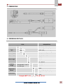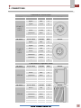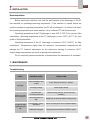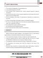
1
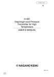
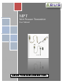
MPT Melt Pressure Transmitter User Manual ABUS TECHNOLOGIES INC. MPT WARNING This manual should be passed on to the end user. The contents of this manual are subject to change without prior notice. All rights reserved. ABUS gives no warranty of any kind with regard to this manual, including, but not limited to, fitness for a particular purpose. If any question arises or errors are found, or if any information is missing from this manual, please inform your supplier or inform at [email protected]. The specifications mentioned in this manual are limited to those for the standard type under the specified model number break-down and do not necessarily apply for customized instruments. Please note that changes in the specifications, construction, or component parts of the instrument may not immediately be reflected in this manual at the time of change. If the customer or any third party is harmed by the use of this product, ABUS assumes no responsibility for any such harm owing to any defects in the product which were not predictable, or for any indirect damages. Although Warning hazards are related to personal injury, and Caution hazards are associated with equipment or property damage, it must be understood that operation of damaged equipment could, under certain operational conditions, result in degraded process system performance leading to personal injury or death. Therefore, comply fully with all Warning and Caution notices. Information in this manual is intended only to assist our customers in the efficient operation of our equipment. Use of this manual for any other purpose is specifically prohibited and its contents are not to be reproduced in full or part without prior approval of Technical Communications Department, ABUS Technologies HEALTH AND SAFETY To ensure that our products are safe and without risk to health, the following points must be noted: 1. The relevant sections of these instructions must be read carefully before proceeding. 2. Warning labels on containers and packages must be observed. 3. Installation, operation, maintenance and servicing must only be carried out by suitably trained personnel and in accordance with the information given. Any deviation from these instructions will transfer the complete liability to the user. 4. Normal safety precautions must be taken to avoid the possibility of an accident occurring when operating in conditions of high pressure and/or temperature. 5. Chemicals must be stored away from heat, protected from temperature extremes and powders kept dry. Normal safe handling procedures must be used. 6. When disposing of chemicals ensure that no two chemicals are mixed. Safety advice concerning the use of the equipment described in this manual or any relevant hazard data sheets (where applicable) may be obtained from the Company address on the back cover, together with servicing and spares information. ABUS TECHNOLOGIES INC. 2 MPT . CATALOGUE Contents Page No. 1. Introduction 4 2. Presentation 4 4 4 1. Features 2. Technical Parameters 3. Dimensions 5 4. Ordering Details 5 5. Connections 6 6. Installation 7 7 Recommendation 7. Maintenance Troubleshooting 7 7 8. Safety Precautions 8 9. Warranty 8 ABUS TECHNOLOGIES INC. 3 MPT 1. INTRODUCTION The MPT-P&T Series transmitter is a +/- 1.0% accuracy sensor ideal for general purpose melt pressure measurements requiring simple installation, repeatability and reliability. The MPT-P&T transmitters provide the industry standard 4 - 20 mA amplified signal designed to work with Recording Indicators and PLCs. The MPT-P&T comes equipped with adjustable zero and span ports. Optional thermocouple or RTD configurations are available to provide melt temperature. The MPT-P&T features a 1/2-20 UNF thread for installation in standard transducer mounting holes and can be supplied with a variety of electrical connections. 2. PRESENTATION 2.1 Features 1. Adjustable zero and span 2. Stainless steel wetted parts 3. 0 - 500 to 0 - 10,000 psi 4. Accuracy better than +/- 1.0% 5. 4 - 20 mA outputs 6. Internal 80% shunt calibration 7. Repeatable, reliable pressure measurements 8. Superior abrasion resistance 9. Direct input to supervisory control systems 10. Easy to install and set-up 11. Wide variety of pressure and temperature combination. 2.2 Technical Parameters Range: 0~10 bar – 2000 bar, (0~150 PSI – 30000 PSI) Accuracy: ±0.50 % FS, ± 1.0 % FS Power: 10Vdc Output: 1.5mV/V, 2mV/V, 2.5 mV/V, 3.33 mV/V Load resistance: 350 ohms±10% Shunt calibration: 80%±1% Overload: 1.5×FS Repeatability: ±0.2%FS Thermocouple: PT 100; E; J; K Max diaphragm temp: Process connection Up to 500 °C 1/2″- 20UNF, M14×1.5, M18×1.5, M22, G3/4 Electronic connection: 6-pin or 8-pin along with connector and cable. ABUS TECHNOLOGIES INC. 4 MPT 3. DIMENSIONS All dimensions in mm 4. ORDERING DETAILS TYPE Product DESCRIPTION MPT Melt Pressure Transmitter Flexible Type with capillary F Type S * Stem Type P&T Lower Range Pressure & Temperature Type __ Upper Range __ Temperature Sensor Accessories Specify Upper Range 3 6 9 12 Stem Length Capillary Length Specify Lower Range * Not applicable in case of “S” or Stem type. N 18 30 N B S Y N 3”, 75 mm 6”, 150 mm 9”, 225 mm 12”, 300 mm No Capillary 18”, 450 mm 30”, 750 mm None Blank, No temperature Sensor Single J TC with 3” Capillary With cable and Female connector. None Example: MPT > S > __ > __ > 3 > N > N > N ABUS TECHNOLOGIES INC. 5 MPT 5. CONNECTIONS Connections for Pressure Sensor OUTPUT 3.33 mV / V 0-5 V 0-10 V OUTPUT 3.33 mV / V 0-5 V 0-10 V FUNCTION COLOR 6PIN Signal + Blue A Signal - Green B Power + Red C Power - Yellow D Calibration Black E Calibration Brown F FUNCTION COLOR 8PIN Signal + Blue A Signal - Green B Power + Red C Power - Yellow D Calibration Black E Calibration Brown F -- -- G IMAGE IMAGE Connections For Temperature Sensor OUTPUT 4~20 mA OUTPUT 4~20 mA FUNCTION COLOR 6PIN Power + Red A Power - Blue B Calibration Black E Calibration Brown F FUNCTION COLOR LEAD Power + Red A Power - Yellow B Calibration Black E Calibration Brown F ABUS TECHNOLOGIES INC. IMAGE IMAGE 6 MPT 6. INSTALLATION Recommendation Before starting the machine, wait until the melt medium at the diaphragm of the PT has reached its operating/processing temperature. If the machine is started before the medium reaches its operating temperature, the PT will be damaged. If it is hard to tell when the operating temperature has been reached, use a combined PT with thermocouple. Operating temperature at the PT diaphragm is max. 400°C (752°F) for mercury filled transmitters. Operating temperature at the PT diaphragm is max. 325°C (617°F) for food grade oil filled transmitters. Operating temperature at the PT diaphragm is maximum 518°C (1000°F) for filled transmitters. Temperatures higher than the maximum recommended temperatures will damage the PT. Ambient temperature for the electronics housing is maximum +85°C. Higher range temperatures can result in damage and malfunction. Do not install the pressure transmitter in places where this temperature is exceeded. 7. MAINTENANCE Troubleshooting FAULT POSSIBLE CAUSE RESOLUTION Cable breakage or poor contact Check cable and contact, or replace. No supply voltage Check supply voltage. Mounting hole incorrectly produced Check hole with test bolt, review with tool if necessary. Mounting torque too high Adjustment to recommended mounting torque. Plug forming in front of diaphragm Check mounting hole; remove solidified plastic. Diaphragm damaged Send pressure transmitter to ABUS for repair. No signal String zero shift when screwing in No signal change despite pressure rise ABUS TECHNOLOGIES INC. 7 MPT 8. SAFETY PRECAUTIONS 1. The unit should be powered for 15 minutes before use. 2. Use in ambient temperature of 0-60˚C. 3. Avoid vibrations, shock, excessive dust, corrosive chemical materials or gaseous environment. 4. Input wire should not be too long. If measured signal have to be far away from the unit, please use 2-core shielded cable. 5. Use this instrument in the scope of its specifications, otherwise fire or malfunctions may result. 6. Contact of the instrument, with organic solvents or oils should be avoided. 7. Do not turn on the power supply until all of the wiring is completed. Otherwise electrical shock, fire or malfunction may result. 8. Do not disassemble, repair or modify the instrument. 9. All connections should be tightened properly. 10. Power supply should be constant, should not be fluctuating. 9. WARRANTY ABUS provides the original purchaser of this instrument a one (1) year warranty against defects in material and workmanship under the following terms: The one year warranty begins on the day of shipment as stated on the sales bill. During the warranty period all costs of material and labor will be free of charge provided that the instrument does not show any evidence of misuse. For maintenance, return the instrument with a copy of the sales bill to our factory. All transportation and insurance costs should be covered by the owner of the equipment. Should any sign of electrical or mechanical shock, abuse, bad handling or misuse be evident the warranty voids and maintenance costs will be charged. ABUS TECHNOLOGIES INC. www.abustek.com, E-Mail: [email protected] ABUS TECHNOLOGIES INC. 8