1
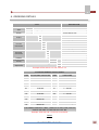
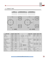
PT Series Pressure Transmitters
User Manual
ABUS TECHNOLOGIES INC.
PT
WARNING
v
This manual should be passed on to the end user.
v
The contents of this manual are subject to change without prior notice.
v
All rights reserved.
v
ABUS gives no warranty of any kind with regard to this manual, including, but not limited to, fitness for a
particular purpose.
v
If any question arises or errors are found, or if any information is missing from this manual, please inform
your supplier or inform at [email protected].
v
The specifications mentioned in this manual are limited to those for the standard type under the specified
model number break-down and do not necessarily apply for customized instruments.
v
Please note that changes in the specifications, construction, or component parts of the instrument may
not immediately be reflected in this manual at the time of change.
v
If the customer or any third party is harmed by the use of this product, ABUS assumes no responsibility
for any such harm owing to any defects in the product which were not predictable, or for any indirect
damages.
Although Warning hazards are related to personal injury, and Caution hazards are associated with
equipment or property damage, it must be understood that operation of damaged equipment could, under
certain operational conditions, result in degraded process system performance leading to personal injury or
death. Therefore, comply fully with all Warning and Caution notices.
Information in this manual is intended only to assist our customers in the efficient operation of our
equipment. Use of this manual for any other purpose is specifically prohibited and its contents are not to be
reproduced in full or part without prior approval of Technical Communications Department, ABUS
Technologies
HEALTH AND SAFETY
To ensure that our products are safe and without risk to health, the following points must be noted:
1. The relevant sections of these instructions must be read carefully before proceeding.
2. Warning labels on containers and packages must be observed.
3. Installation, operation, maintenance and servicing must only be carried out by suitably trained personnel
and in accordance with the information given. Any deviation from these instructions will transfer the
complete liability to the user.
4. Normal safety precautions must be taken to avoid the possibility of an accident occurring when operating
in conditions of high pressure and/or temperature.
5. Chemicals must be stored away from heat, protected from temperature extremes and powders kept dry.
Normal safe handling procedures must be used.
6. When disposing of chemicals ensure that no two chemicals are mixed.
Safety advice concerning the use of the equipment described in this manual or any relevant hazard data
sheets (where applicable) may be obtained from the Company address on the back cover, together with
servicing and spares information.
ABUS TECHNOLOGIES INC.
2
PT
.
CATALOGUE
Contents
Page No.
4
4
1. Introduction
Applications
2. Presentation
1. Features
2. Technical Parameters
4
4
5
3. Dimensions
5
4. Ordering Details
6
5. Connections
7
8
9
7
9
9
10
10
10
Output Characteristics
6. Installation
Recommendation
7. Operation
1. Zero and Span Adjustment Procedure
2. Example for Usage
8. Maintenance
Troubleshooting
9. Safety Precautions
11
10. Warranty
11
ABUS TECHNOLOGIES INC.
3
PT
1. INTRODUCTION
PT Series of Pressure Transmitters are precision engineered to fit most industrial
pressure measurement applications. The compact, rugged design make these instruments
suitable for applications including hydraulics and pneumatics, vacuum, test equipment,
liquid level measurement, pressure control, compressor control, pump protection and
numerous other processing and control operations. A wide range of electrical connection
and process connection options are available to meet almost every requirement.
The PT Series features an all-welded stainless steel measuring cell for improved
media compatibility. There are no internal soft sealing materials that may react with the
media or deteriorate over time. The compact case is also made of stainless steel and is
available with environmental protection ratings.
PT Series industrial Pressure transmitter adopts high performance chips and deals
with special amplified chip, integrative configuration, and smart profile. They are widely
used in field of hydraulic pressure, chemical, petro-chemical, power, food, pharmaceutical
and, OEM Applications.
Applications
•
Industrial OEM Equipment
•
HVAC / R Equipment
•
Water Management
•
Process Control
•
Pneumatics Pressure
•
Hydraulic Systems
2. PRESENTATION
2.1 Features
1. Stainless steel wetted parts.
2. Excellent resistance to corrosive processes.
3. Small figure design, any position to install.
4. Various optional signal output.
5. OEM process to fit application of the customers.
ABUS TECHNOLOGIES INC.
4
PT
2.2 Technical Parameters
Accuracy:
±0.25%FS (BFSL)
±0.5%FS (limit point calibration)
Ranges:
Absolute:
0…1 to 0…50 bar, 0…15 to 0…750 psi
Vacuum:
(-1)… bar, (-15)…0 psi
Gauge:
0…100mB to 0…1000 bar, 0…1.5 to 0…15000 psi
Output:
0...5 V, 0...10 V, 0.5...4.5 V, 4...20 mA (Customized On request)
Power Supply:
24Vdc (10~36Vdc)
Maximum Pressure:
1.5 x F.S.
Adjustability Zero / Span:
± 10 % using potentiometers inside.
Electrical Connections:
M12 connector, Five Pin bendix connector, Hirschman Type or Direct
down-lead.
Process Connection:
G1/4, M20 x 1.5, 1/4NPT (Customized On request)
Pressure Inlet:
All media compatible with stainless steel 316
Operating temperature:
-40 ~ 85°C (125°C for short durations) * Higher range, on request.
Ambient temperature:
-20 ~ +80°C
Wetted Parts:
SS 316L / Al2O3 / NBR
Case:
Stainless steel
Housing:
Stainless steel, protection class IP65.
3. DIMENSIONS
All dimensions in mm
ABUS TECHNOLOGIES INC.
5
PT
4. ORDERING DETAILS
TYPE
Type
DESCRIPTION
PT10
Absolute Pressure Transmitter
PT20
Gauge/Compound Pressure Transmitter
PT30
Vacuum Pressure Transmitter
Range
0 ~ 25 bar
-1 ~ 0 ~ 1800 bar
-760 ~ 0 mmHG
Specify Range code
__
Output
D
4 ~ 20 mA
V
0 ~ 10 V
A
Process
Connection
Others, specify
A
G 1/4”
E
O
G 1/2”
1/4” NPT
U
Others, specify
Electrical
Connection
W
DIN Connector (Hirschman Type)
X
Y
Thread Screw
Bendix Connector
Z
Integral
Indicator (Refer
LPI-PT)
Direct Down-lead
+ LPI-PT
Loop Powered Indicator
0
W/O Indicator
Zero and Span
Adjustment
1
With Internal Z & S
0
W/O
Example: PT20 >10 > D > 1 > W > LPI-PT > 1
STANDARD RANGES FOR PT SERIES
CODE
GAUGE/ABS. PRESSURE
CODE
COMPOUND
01
02
03
04
05
06
07
08
09
10
11
12
13
14
15
16
1.00 bar
1.60 bar
2.50 bar
4.00 bar
6.00 bar
10.00 bar
16.00 bar
20.00 bar
25.00 bar
40.00 bar
60.00 bar
100.00 bar
160.00 bar
200.00 bar
250.00 bar
400.00 bar
17
18
19
20
600.00 bar
1000.00 bar
1500.00 Bar
1800.00 Bar
41
42
43
44
45
46
COMPOUND
-1 ~ 0.6 bar
-1 ~ 1.0 bar
-1 ~ 2.0 bar
-1 ~ 3.0 bar
-1 ~ 5.0 bar
-1 ~ 9.0 bar
61
VACUUM
-760 ~ 0 mm/Hg
CUSTOMIZED RANGES & UNITS - MARK 00 AS THE CODE, SPECIFY
RANGE AND UNIT AT THE END OF PART NO.
Example: PT20 >00 > D > 1 > W >0 > 0 >0-50 PSI
Table 1
ABUS TECHNOLOGIES INC.
6
PT
5. CONNECTIONS
WIRE
SIGNAL OUTPUT
EXCITATION
2-wire
4 ~ 20mA
12 ~ 36 Vdc
3-wire
0 ~ 10 Vdc
12 ~ 18 Vdc
ABUS TECHNOLOGIES INC.
7
PT
Output Characteristics (FOR PT20-12XXXX Pressure Transmitter)
A
B
C
D
C
D
ABUS TECHNOLOGIES INC.
8
PT
6. INSTALLATION
Recommendation
1. Please confirm the configuration for Pressure Transmitter i.e. 2- wire, 3-wire and accordingly follow the
wiring procedure. Ensure that the excitation voltage is supplied to the correct points and is with in the
specified limits for that particular configuration as mentioned in the table above.
2. When installed, ensure that the transmitter is not subjected to the excessive sources, and it should be
considered before installing the Transmitter. Use suitable diaphragm if needed.
3. Process connection must be properly sealed with material compatible with the process liquid / gas.
4. When installing transmitter with diaphragm, seals / process connector should be tightened not the
transmitter, otherwise transmitter calibration may get affected.
7. OPERATION
7.1 Zero and Span Adjustment Procedure
Minor adjustment can be made to the output signal in case of any drift. The procedure for same is indicated
as below:
1. On top of the Pressure Transmitter is the DIN Connector. Remove it by first removing the screw.
2. Four Terminals will be found on top of which will be a rubber washer. Remove the rubber washer
gently.
3. This next step is crucial and to be done very gently. Holding the PT in the palm of the hand, press
down the four terminals and revolve the thread, such that the terminals do not move at all. This is
necessary as the wiring inside the casing might get twisted and the device will be damaged.
4. After the thread is removed, gently lift the terminals. Inside is a PCB, and on each side of the PCB are
two Potentiometers (covered under white wax) using which the Zero and Span adjustments will be
done.
5. The symbols Z & S are etched on the body of the PT casing just below the terminals. Z indicates the
potentiometer for Zero adjustment and S for Span adjustment.
6. Two wires, one for power and one for input are connected and the output is taken.
7. If while applying a pressure of 0 bar, the output deviated from standard Zero Signal (4 mA in case the
output is 4-20 mA). Then the Zero adjustment has to be done till the output is exactly 4 mA. The
same way, the Span adjustment is done with the S potentiometer by applying the full span pressure
and getting an output of exactly 20 mA.
8. After adjustment is done, replace the thread, washer and DIN connector in the reverse order.
ABUS TECHNOLOGIES INC.
9
PT
7.2 Example for Usage
8. MAINTENANCE
Troubleshooting
S. No.
SPECIFICATIONS
ELIMINATE
1
No output
•
•
Check the wiring configuration.
Check the input power supply.
2
No variation in output
•
•
Check for leakage at pressure port / point.
Check the span set of Indicating Instrument.
3
Pressure not holding
at constant input
pressure.
•
•
Check for leakage pressure point.
Check for the connections ensure they are properly
tightened.
ABUS TECHNOLOGIES INC.
10
PT
9. SAFETY PRECAUTIONS
1. The unit should be powered for 15 minutes before use.
2. Use in ambient temperature of 0-60˚C.
3. Avoid vibrations, shock, excessive dust, corrosive chemical materials or gaseous environment.
4. Input wire should not be too long. If measured signal have to be far away from the unit, please use 2core shielded cable.
5. Use this instrument in the scope of its specifications, otherwise fire or malfunctions may result.
6. Contact of the instrument, with organic solvents or oils should be avoided.
7. Do not turn on the power supply until all of the wiring is completed. Otherwise electrical shock, fire or
malfunction may result.
8. Do not disassemble, repair or modify the instrument.
9.
All connections should be tightened properly.
10. Power supply should be constant, should not be fluctuating.
10.
WARRANTY
ABUS provides the original purchaser of this instrument a one (1) year warranty against defects in
material and workmanship under the following terms:
•
The one year warranty begins on the day of shipment as stated on the sales bill.
•
During the warranty period all costs of material and labor will be free of charge provided that the
instrument does not show any evidence of misuse.
•
For maintenance, return the instrument with a copy of the sales bill to our factory.
•
All transportation and insurance costs should be covered by the owner of the equipment.
•
Should any sign of electrical or mechanical shock, abuse, bad handling or misuse be evident the
warranty voids and maintenance costs will be charged.
REV01(070710)
•
Ordering Code updated for better understanding.
•
Output characteristics included for 4-20 mA O/P.
•
Zero and Span Adjustment procedure added
REV02(080710)
•
Output Characteristics Graph A modified
•
Dimension Diagram Changed
• Connection Table Changed
ABUS TECHNOLOGIES INC.
www.abustek.com, E-Mail: [email protected]
ABUS TECHNOLOGIES INC.
11