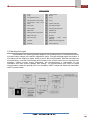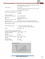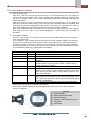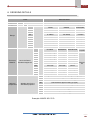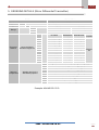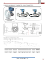
1
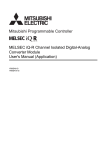
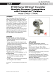
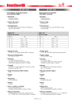
DPT
Smart Pressure/DP Transmitter
User Manual
Flanged Diaphragm
Type
ABUS TECHNOLOGIES INC.
M94
WARNING
v
This manual should be passed on to the end user.
v
The contents of this manual are subject to change without prior notice.
v
All rights reserved.
v
ABUS gives no warranty of any kind with regard to this manual, including, but not limited to, fitness for
a particular purpose.
v
If any question arises or errors are found, or if any information is missing from this manual, please
inform your supplier or inform at [email protected]
v
The specifications mentioned in this manual are limited to those for the standard type under the
specified model number break-down and do not necessarily apply for customized instruments.
v
Please note that changes in the specifications, construction, or component parts of the instrument
may not immediately be reflected in this manual at the time of change.
v
If the customer or any third party is harmed by the use of this product, ABUS assumes no
responsibility for any such harm owing to any defects in the product which were not predictable, or for
any indirect damages.
v
The integral modules specifically HART module are not manufactured by ABUS.
Although Warning hazards are related to personal injury, and Caution hazards are associated with
equipment or property damage, it must be understood that operation of damaged equipment could, under
certain operational conditions, result in degraded process system performance leading to personal injury
or death. Therefore, comply fully with all Warning and Caution notices.
Information in this manual is intended only to assist our customers in the efficient operation of our
equipment. Use of this manual for any other purpose is specifically prohibited and its contents are not to
be reproduced in full or part without prior approval of Technical Communications Department, ABUS
Technologies.
HEALTH AND SAFETY
To ensure that our products are safe and without risk to health, the following points must be noted:
1. The relevant sections of these instructions must be read carefully before proceeding.
2. Warning labels on containers and packages must be observed.
3. Installation, operation, maintenance and servicing must only be carried out by suitably trained
personnel and in accordance with the information given. Any deviation from these instructions will
transfer the complete liability to the user.
4. Normal safety precautions must be taken to avoid the possibility of an accident occurring when
operating in conditions of high pressure and/or temperature.
5. Chemicals must be stored away from heat, protected from temperature extremes and powders kept
dry. Normal safe handling procedures must be used.
6. When disposing of chemicals ensure that no two chemicals are mixed.
Safety advice concerning the use of the equipment described in this manual or any relevant
hazard data sheets (where applicable) may be obtained from the Company address on the back cover,
together with servicing and spares information.
ABUS TECHNOLOGIES INC.
2
M94
CATALOGUE
Contents
Page No.
1. Introduction
4
2. Presentation
1. Structure Overview
2. Working Principle
3. Dimensions
4. Technical Parameters
1. Push Button Functions
4
4
5
6
6
8
3. Electrical Connections
9
4. Ordering Details
11
5. Ordering Details (Micro Differential Transmitter)
12
6. Ordering Details (M94DL)
14
7. Safety Precautions
15
8. Warranty
15
ABUS TECHNOLOGIES INC.
3
M94
1. INTRODUCTION
The ABUS DP Series features high performance with high degree of precision.
Differential pressure measurement can be used to measure flow, level, density and viscosity.
This versatile primary measurement can provide high accuracy results even in harsh
environmental conditions. It is considered on the basis of the proven and reliable sensing
technology and extensive digital technology.
16-bit single chip is adopted as its core element, with its powerful function and highspeed processing capacity, ensures the excellent accuracy with stability of the transmitter. The
whole design frame focuses on its reliability, stability and high precision, meeting the growing
demand of on-site industrial use. To achieve this goal, digital signal processing is used by the
software to ensure minimum disturbance effects and zero point stability. Meanwhile, it has the
Zero Stability Capacity (ZSC) and Temperature Supplementing Capacity (TSC).
The powerful interface guarantees an excellent interaction rarely needing manual
operator. Keypad operation can accomplish the basic settings of zero, range setting, damping
setting under the circumstances of no standard pressure, and proving to be very convenient for
the on-site adjustments.
By connecting with module RS485, it can realize the remote transmission of digital signal
or the building up of RS485 industrial LAN.
Transmitter has an optional HART module. Transmitter added the HART module has
HART communication capabilities, with the conventional operations being controlled by the
manual operator. Transmitter can be widely used in the sectors such as petroleum, chemical,
iron & steel, power supply, light industry and environmental protection, capable of realizing the
measurement of various pressures, differential pressures, flows and fluids, can adapt for all kinds
of harsh and hazardous environment and corrosive processes.
2. PRESENTATION
2.1 Structure Overview
ABUS TECHNOLOGIES INC.
4
M94
Description
1
Cover
14
Cover lock bolt
2
3
O-ring
Wiring terminals cover
15
16
Sensor
O-ring
4
Mounting bolts of circuit board
17
O-ring
5
Thunder-proof
board
18
Position code plate
6
Name plate
19
Zero alignment plate
7
Housing body
20
Housing body lockup bolt
8
Meter head
21
Parallel wires
9
Mounting bolts of meter head
22
Circuit board
10
Meter head cover
23
Nut M10
11
Drain/ vent valve
24
Integrated
(optional)
12
Template
25
Welded connector (optional)
13
Bolts M10
26
Flange (optional)
wiring
circuit
3-valve
group
2.2 Working Principle
As indicated in the working principle diagram, the outside pressure or differential pressure
will cause some change in the sensor capacitance value. Through the digital signal conversion, it
will change into the frequency signal, which is sent to the microprocessor. After the calculation by
microprocessor, a current control signal will be output to the current control circuit, converted into
analogue 4-20mA current output. Meanwhile, the microprocessor is responsible for the
interactive and other actions (display and setting). The communication port used for digital
communication needs the special port of our company. HART module will realize the transmitter
HART communication.
ABUS TECHNOLOGIES INC.
5
M94
2.3 Dimensions
Type
1200
1300
Size (mm)
Type
1400
1500
1600
54
2400
1700
1800
1900
1000
2300
57.2
58.4
59.2
54
5600
6600
7600
8600
9600
6800
7800
8800
55.6
2500
2600
6700
7700
2700
2800
M
Size (mm)
Type
54
5700
Size (mm)
55.6
8700
57.2
9700
55.6
55.6
57.2
NOTE: Pl refer to product manual for any changes
2.4 Technical Parameters
Output Signal:
4 ~ 20mA DC, 2-Wire System with Digital communication,
Reference Accuracy:
±0.075%
Range ability
100 : 1
Overall Performance:
± 0.1 % (for range of 1/10 of max allowed span) including
comprehensive inaccuracy of linearity, changing difference and
repeatability.
Stability:
±0.15% of the span; for Draft Ranges, ±0.25% of the span.
Start-Up time:
Max 2 seconds for minimum damping.
Volume Change:
Less than 0.16cm3.
Response Time:
Less that 100 ms
Damping:
Electrical damping is 0 ~ 32 seconds, continually adjustable at
an interval of 0.1 second. Sensitive components have 0.2
seconds constant damping time. (Span 3 is 0.4 seconds)
Functions:
PushButton configurable Linear/Square root
Effect of Temperature:
Zero Inaccuracy: Max. ±0.25% of span for each 50F (28°C).
Vibration Effect:
At time of 0 ~ 200Hz for shock frequency on any direction, the
error is 0.05%/g of the highest one.
Power Effect:
Less than output range by ±0.005%/V.
ABUS TECHNOLOGIES INC.
6
M94
Mounting Orientation Effect:
Zero drifts no more than 0.24kPa. No effect for movement
parallel to diaphragm. The error could be resolved by quick Zero
reset pushbutton on the instrument.
Power Voltage:
12V ~ 45V DC
Intrinsically safe/explosion-proof products with max 30 VDC
should be powered by safe Barrier
Parameters for intrinsically safety: U0 ≤ 28V DC,
type outsourcing safe barrier
I0 ≤ 30mA
P0 ≤ 0.84W
Physical Parameters:
O Ring of Contacting Medium:
Viton / Glass Filled PTFE
Filling liquid:
Silicone Oil / Inert Gas
Bolt:
Cadmium plated carbon steel.
Outer shell or electronic circuit:
Low Cu Al.
O shaped seal ring:
Acrylotrile-butadiene rubber, fluorine rubber polyurethane.
NOTE: Please refer to Ordering Table for Flange connector, Exhaust/Vent valves and Isolation
Diaphragm Material options
Pressure Connection Part:
¼ - 18 NPT for joint thread in pressure room,
½ - 14 NPT for joint thread in pressure guiding joint.
Weight:
Basic Model, 2.4Kg
Operation Environment under Normal Conditions
Operation Temperature(Ambient): Smart Type:-20°C ~ +85°C.
Storage Temperature:
-40°C ~ +104°C
Humidity:
0 ~ 90%
Atmospheric Pressure:
86 ~ 106 kPa
Operation Environment Conditions for Explosion-Proof Product
Humidity:
-20°C ~ +40°C
Relative Humidity:
5% ~ 95%
Atmospheric Pressure:
86 ~ -106 kPa
ABUS TECHNOLOGIES INC.
7
M94
2.4.1 Push Button Functions
1. Zero & Span Shift
Zero Shift : push key S & Z at the same time (key S on the left while key Z on the right) for 6
seconds, the screen indicates “Hart”, means zero and span adjustment status is activated; push
key Z for 5 seconds, “Hart” on the screen disappeared; zero shifts successfully and exits the
status of activation.
Span Shift: push key S & Z at the same time (key S on the left while key Z on the right) for 6
seconds, the screen indicates “Hart”, means zero and span adjustment status is activated; after
confirming the pressure of equipment is span pressure, push key S for 6 seconds; then “Hart” on
the screen disappeared; span shifts successfully and exits the status of activation.
Note: After entering the status of activation, if you don’t want to adjust, push key S & Z together;
after loosing the key, “Hart” on the screen disappears; it means having exit the status of
activation.
2. Parameter Setting
2-1 keys : Push key S & Z = exit key; exit key comes into force after loosing key S & Z; push key
Z for 4 seconds to shift
2-2 Parameters : After pushing key S for 6 seconds, the screen indicates “PASS”; then push key
Z, the screen indicates value and the cursor flickers. The flickering bit is modifier bit; push key Z
the value increases 1 but not carry. Push key Z for 4 seconds the cursor shifts. Follow the above
mentioned operation to revise the value to be 160, then push key S to enter adjustment procedure
of next parameter. Meanings of parameters are as follows:
Parameter Prompt
Value
PASS
bdSh
bdSL
trAn
XXXXX
XXXX.X
XXXX.X
XXXXX
UnIt
XXXXX
dAhP
PrEL
XXXX.X
XXXXX
PrEh
XXXXX
InIt
yes/no
Meaning
Password Verification, PW: 160
Process value to 20 mA (full scale value)
Process Value to 4 mA (zero value)
Transmitting function, “=0” stands for linearity, “=1” stands for
evolution
Indicating units, 0=KPa, 1=KPa, 2=KPa, 4=KPa, 6=Pi, 7=bar,
8=KPa, 9=KPa, 11=Pa, 12=KPa, 13=KPa, 15=MPa, 16=mA,
17=%, 18=S, 19=m3, 20=t/h
Damping time, max limited value is 30 s when program runs
Low point trimming. Process value adjusted to input value; after
pushing key Z revise low point trimming pressure value; don’t
push key Z if you don’t want to adjust; directly push key S to
enter next parameter
High point trimming. Process value adjusted to input value;
after pushing key Z revise high point trimming pressure value;
don’t push key Z if you don’t want to adjust; directly push key S
to enter next parameter
Hart. Three-point linearization and trimming data initialization
Hotkey: push key Z for 6 seconds to do zero trimming
Note: Please operate carefully for italic part parameters; make sure correct value of pressure
forced on equipment
2
3
DETAILS
1
4
1 Rotating Display
2 Bright White Backlit Display
3 Bar Graph Display
4 Display in various Engineering Units
5 Zero Button
6 Span Button
5
6
ABUS TECHNOLOGIES INC.
8
M94
3. ELECTRICAL CONNECTIONS
Electrical Port: :NPT1/2 load resistance of cable sealed connector: (4-20mA)
=
− 14
−
0.02
where: U is power voltage, RD is cable internal resistance
(Note 1: User can install the distributor or safe barriers per the on-site and design
requirements. For details, see the usage of distributor and safe barrier.)
It is recommended to choose the explosion-proof impulse terminal with the cable
diameter of ö8 – 12. The connection terminal is set with test terminal, convenient for the online
test of the operator.
Signal terminal is situated in a separate housing of the electrical box. Screw up the meter
cover for wiring. The upper end is for signal, while the lower end is for test meter. Fig. 2-13
indicated the terminal location. The test terminal is used for connecting any optional indicator
ABUS TECHNOLOGIES INC.
9
M94
head or test. The power supply goes to the transmitter through the signal line, with no need of
additional wiring.
Special Attention:
Do not connect the power signal line to the test terminal; otherwise the
diode inside the test terminal would be destroyed
In case of the diode being damaged unfortunately, connecting the test terminal can keep
the transmitter working on, except the indicator unable to connect.
No need to shield the signal wire, and litz wire can be used for better effect. Do not lay
together the signal wire and other power wires, to get near to the strong electricity equipment.
The wiring orifice on the housing body of transmitter should be sealed or inserted in a
plug smeared with seal glue to prevent the humidity being accumulated in the housing. In the
case of the wiring not being sealed, the transmitter should be mounted with the wiring orifice
upside down to discharge the moisture.
The signal line may ignore the grounding (hanging) or get to ground at any point on the
loop line. The transmitter housing can have grounding or not, and the power has no need of
being stabilized, even if the power ripples has a peak-to-peak value of 1V. And the output ripples
of transmitter can also be ignored.
Since the transmitter gets grounded by way of capacitance coupling, it is not appropriate
to use a high-voltage mega-ohm meter to check the insulation resistance. The voltage used for
checking the line should be no more than 100 V.
The transmitter circuitry is designed as intrinsic safe circuitry, limiting the output current
below 30 mA DC (35 mA DC under the condition of high temperature or high voltage).
Intrinsically Safety Type Explosion Proof Transmitter System Wiring Diagram
Ui:
li:
Pi:
28V DC
30mA
0.84W
Um ≥ 250V AC/DC
Uo ≤ 28V DC
lo ≤ 30mA
Po ≤ 0.84W
Note: See GB3836, 4-2000 standard for the definitions of Um, Uo, lo, Po, Ui, li, Pi
The connection wire or cable between safe barrier and transmitter has a largest allowed
distribution capacitance of no more than 0.02µF and the largest allowed distribution inductance
of not more than 2.0mH.
ABUS TECHNOLOGIES INC.
10
M94
4. ORDERING DETAILS
TYPE
Product
Type
DESCRIPTION
M94
Smart Transmitter with HART Communication
Differential Pressure
DP
D
B1
B2
B3
D1
STATIC
PRESSURE
1.2~7.2kPa
-7.2~7.2kPa
2.5MPa
1.2~7.2kPa
-7.2~7.2kPa
6.4 MPa
6~36kPa
-36~36kPa
6.4 MPa
30~180kPa
-180~180kPa
6.4 MPa
6~36kPa
-36~36kPa
16 MPa
30~180kPa
-180~180kPa
16 MPa
160~1000kPa
-1000~1000kPa
40 MPa
400~2500kPa
-2500~2500kPa
40 MPa
1600~10000kPa
-10000~10000kPa
32 MPa
FILL
FLANGE
DRAIN/VENT DIAPHRAGM
LIQUID
CS CD-plating
316 L SS
316 L SS
CS CD-plating
Hastelloy C
Hastelloy C
CS CD-plating
Monel
Monel
CS CD-plating
316 L SS
Tantalum
316 L SS
316 L SS
316 L SS
Silicone
316 L SS
316 L SS
Hastelloy C
Oil
316 L SS
316 L SS
Monel
316 L SS
316 L SS
Tantalum
Hastelloy C
Hastelloy C
Hastelloy C
Hastelloy C
Hastelloy C
Tantalum
Monel
Monel
Monel
Digital Backlit LCD Indicator(with programming keys)
Bend bracket for pipe mounting (2” pipe)
Bend Bracket for plate mounting
Flat bracket for pipe mounting (2” pipe)
Side exhaust/vent valve of flange on top
D2
W*
E
I
Side exhaust/vent valve of flange on bottom
WeatherProof Type
Explosion Proof Type
Intrinsically Safe Type
SPAN
Range
Structure
Material
Optional
Components
33
53
54
55
64
65
96
97
88
L22 is the Part of
Standard equipment
L12
L13
L14
L15
L22*
L23
L24
L25
L33
L35
L44
Weather proof is the
Standard equipment
RANGE
Example: M94 DP 65 L22 D
ABUS TECHNOLOGIES INC.
11
M94
5. ORDERING DETAILS (Micro Differential Transmitter)
TYPE
Product
Type
Range
DESCRIPTION
M94
Smart Transmitter with HART Communication
Differential Pressure
SPAN
RANGE
0.20~2kPa
-0.2~+2kPa
0.06~0.3kPa
-0.3~0.3kPa
MD
12
10
FLANGE
Structure
Material
Optional
Components
L22 is the Part of
Standard equipment
L12
L13
L14
L15
L22*
L23
L24
L25
L33
L35
L44
Weather proof is the
Standard equipment
DRAIN/VENT DIAPHRAGM
FILL
LIQUID
D
B1
B2
B3
D1
D2
W*
CS CD-plating
316 L SS
316 L SS
CS CD-plating
Hastelloy C
Hastelloy C
CS CD-plating
Monel
Monel
CS CD-plating
316 L SS
Tantalum
316 L SS
316 L SS
316 L SS
Silicone
316 L SS
316 L SS
Hastelloy C
Oil
316 L SS
316 L SS
Monel
316 L SS
316 L SS
Tantalum
Hastelloy C
Hastelloy C
Hastelloy C
Hastelloy C
Hastelloy C
Tantalum
Monel
Monel
Monel
Digital Backlit LCD Indicator(with programming keys)
Bend bracket for pipe mounting (2” pipe)
Bend Bracket for plate mounting
Flat bracket for pipe mounting (2” pipe)
Side exhaust/vent valve of flange on top
Side exhaust/vent valve of flange on bottom
WeatherProof Type
E
I
Explosion Proof Type
Intrinsically Safe Type
Example: M94 MD 12 L22 D
ABUS TECHNOLOGIES INC.
12
M94
FLANGED DIAPHRAGM DP TRANSMITTER (LEVEL TRANSMITTER)
Remote Sealed Diaphragm DP Transmitters
Direct Flanged Diaphragm
DP Transmitters
C
With Sealing Groove
B
Insert Depth
A
Static Pressure and Overpressure Limit
150lb flange: 15kg/cm2 (at 37° filled with silicon oil)
300lb flange: 30kg/cm2 (at 37° filled with silicon oil)
Connecting Fitting for Process Pressure
High-pressure side :
3” or 4” 150lb flange or 300lb flange
Low-pressure side
:
The connecting thread of the flange is 1/4-18NPT (taper-pipethread)
The connecting thread of the joint is ½-14NPT (taper-pipe-thread)
Code
Size
A
B
C
D
3”
4”
3”
4”
FLANGE SIZE (MM)
Specification
Diameter
150lb
150lb
300lb
300lb
190.5
228.6
209.6
254
A
B
C
Amount
30
30
35
38
66
89
66
89
127
157
127
157
4
8
8
8
BOLT HOLE (MM)
Diameter
Distribution
Diameter
19
152
19
190
22.2
168
22.2
200
ABUS TECHNOLOGIES INC.
13
M94
6. ORDERING DETAILS (M94DL)
TYPE
Product
Type
Range
Diaphragm
Extension
Diaphragm
Material
Capillary
DESCRIPTION
M94
DL
53
64
65
96
97
0
1
2
3
1
2
3
4
00
--
Optional
Weather proof is the Standard
Components
equipment
Smart Transmitter with HART Communication
Flanged Diaphragm (on HP Side) DP Transmitter
SPAN
RANGE
1.2~7.2kPa
-7.2~7.2kPa
6~36kPa
-36~36kPa
30~180kPa
-180~180kPa
160~1000kPa
-1000~1000kPa
400~2500kPa
-2500~2500kPa
None (0 mm)
25 mm
50mm
75mm
SS316L
Hastelloy C
Tantalum
Monel
None
Specify Length in meters
D
Digital Backlit LCD Indicator(with programming keys)
B1
Bend bracket for pipe mounting (2” pipe)
B2
Bend Bracket for plate mounting
B3
Flat bracket for pipe mounting (2” pipe)
D1
Side exhaust/vent valve of flange on top
D2
Side exhaust/vent valve of flange on bottom
W
WeatherProof Type
*
E
Explosion Proof Type
I
Intrinsically Safe Type
Example: M94 DL 64 0 1 00 D
ABUS TECHNOLOGIES INC.
14
M94
7. SAFETY PRECAUTIONS
1.
The unit should be powered for 15 minutes before use.
2.
Use in ambient temperature of 0-60˚C.
3.
Avoid vibrations, shock, excessive dust, corrosive chemical materials or gaseous
environment.
4.
Input wire should not be too long. If measured signal have to be far away from the
unit, please use 2-core shielded cable.
5.
Use this instrument in the scope of its specifications, otherwise fire or malfunctions
may result.
6.
Contact of the instrument, with organic solvents or oils should be avoided.
7.
Do not turn on the power supply until all of the wiring is completed. Otherwise
electrical shock, fire or malfunction may result.
8.
Do not disassemble, repair or modify the instrument.
9.
All connections should be tightened properly.
10. Power supply should be constant, should not be fluctuating.
8. WARRANTY
ABUS provides the original purchaser of this instrument a one (1) year warranty
against defects in material and workmanship under the following terms:
•
The one year warranty begins on the day of shipment as stated on the sales bill.
•
During the warranty period all costs of material and labor will be free of charge
provided that the instrument does not show any evidence of misuse.
•
For maintenance, return the instrument with a copy of the sales bill to our factory.
•
All transportation and insurance costs should be covered by the owner of the
equipment.
•
Should any sign of electrical or mechanical shock, abuse, bad handling or misuse be
evident the warranty voids and maintenance costs will be charged.
ABUS TECHNOLOGIES INC.
www.abustek.com, E-Mail: [email protected]
ABUS TECHNOLOGIES INC.
15