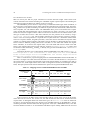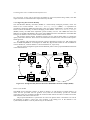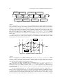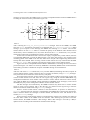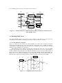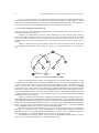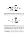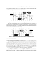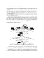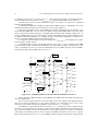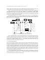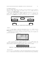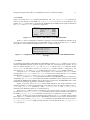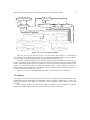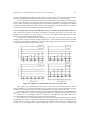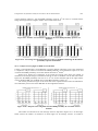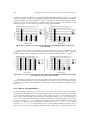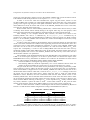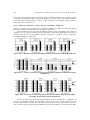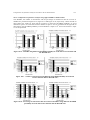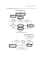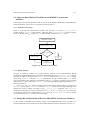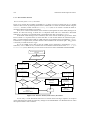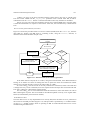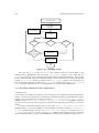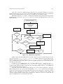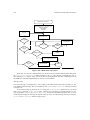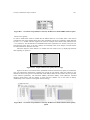
1
www.hurray.isep.ipp.pt
Technical Report
Performance Analysis of Wireless-enabled
PROFIBUS Networks
Paulo Baltarejo Sousa
HURRAY-TR-070607
Version: 1.0
Date: 10-06-2007
Technical Report HURRAY-TR-070607
Performance Analysis of Wireless-enabled PROFIBUS Networks
Performance Analysis of Wireless-enabled PROFIBUS Networks
Paulo Baltarejo Sousa
IPP-HURRAY!
Polytechnic Institute of Porto (ISEP-IPP)
Rua Dr. António Bernardino de Almeida, 431
4200-072 Porto
Portugal
Tel.: +351.22.8340509, Fax: +351.22.8340509
E-mail: [email protected]
http://www.hurray.isep.ipp.pt
Abstract
Most of the industrial community is very reluctant to integrate new technologies in their consolidated automation
systems, either by preconception or by the lack of matureness of these technologies. When addressing communication
systems for control applications, these fears become even more acute. Usually, these communication systems are based
on fieldbus networks, which provide adequate levels of performance, dependability, timeliness and maintainability. The
PROFIBUS (PROcess FIeldBUS) is the most widely used fieldbus, with over 15 million nodes worldwide, in
applications ranging from discrete-part automation to process control.
During the cellular phone and WLAN boom of the last decade, soon it became evident that wireless (radio-based)
communications could leverage a whole new set of potentialities in field level and control applications. Moving parts in
machinery, hand-held equipment, wearable computers, transportation equipment and autonomous vehicles are just a
few examples requiring wireless/mobilecommunications.
However, the requirements of real-time systems, usually served by fieldbuses, impose the use of predictable and reliable
communication services, which provide certain guarantees on eventual delivery of packets and delivery times.
Therefore, running real-time applications using wireless technology can be especially challenging, because the real-time
and reliability requirements are more likely to be jeopardized than they would be over a wired channel.
The RFieldbus architecture, driven by the European Project IST-1999-11316 consortium has provided a complete
solution where multiple segments and multiple wireless cells are interconnected via Physical Layer (PhL) Intermediate
Systems (operating as repeaters). This solution is compatible with standard PROFIBUS, but the fact that all messages
are broadcast throughout the network leads tosome problems, namely no error containment between different segments
and low responsiveness to failures. Additionally, it is also necessary to set the network parameters in a particular way
which guarantees the operation of the network and leads to a lower performance.
These facts triggered the analysis and proposal of an alternative approach where the Intermediate Systems (ISs) operate
at the Data Link Layer (DLL) level as bridges. This approach required two new protocols, one for supporting the
communication between stations in different network segments – the Inter Domain Protocol (IDP), and another to
support the mobility of wireless stations between different wireless segments – the Inter-Domain Mobility Procedure
(IDMP).
The main objective of this dissertation is to compare the timing behaviour of the bridge and repeater-based approaches
over error free and error prone environments. Additionally, we also intended to show that the bridge-based approach
implementation is feasible and propose additional error detection and correction mechanisms which would improve its
performance over error proneenvironments. To achieve these objectives two simulation tools have been developed, one
for the repeater-based approach and another to the bridge-based approach, and a set of result analysis tools.
Additionally, we have also developed another tool to simulate the mobility of wireless stations.
© IPP Hurray! Research Group
www.hurray.isep.ipp.pt
1
UNIVERSIDADE TÉCNICA DE LISBOA
INSTITUTO SUPERIOR TÉCNICO
Performance Analysis of Wireless-enabled PROFIBUS
Networks
Paulo Manuel Baltarejo de Sousa
(Licenciado)
Dissertação para obtenção do Grau de Mestre em
Engenharia Electrotécnica e de Computadores
Orientador: Doutor Luís Miguel Moreira Lino Ferreira
Co-Orientador Doutor Carlos Manuel Ribeiro Almeida
Júri
Presidente: Doutor Mário Serafim dos Santos Nunes
Vogais: Doutor Manuel Alberto Pereira Ricardo
Doutor Luís Miguel Moreira Lino Ferreira
Doutor Carlos Manuel Ribeiro Almeida
Junho de 2007
Table of Contents
CHAPTER 1
OVERVIEW........................................................................................................................................ 1
1.1. Introduction ............................................................................................................................... 1
1.2. Research Context ...................................................................................................................... 2
1.3. Research Objectives .................................................................................................................. 4
1.4. Contributions of this Dissertation ............................................................................................. 4
1.5. Structure of the Dissertation...................................................................................................... 5
CHAPTER 2
TECHNOLOGICAL CONTEXT: COMMUNICATION INFRASTRUCTURE........................ 7
2.1. Introduction ............................................................................................................................... 7
2.2. Relevant Details on PROFIBUS ............................................................................................... 7
2.2.1. General Features ................................................................................................................ 7
2.2.2. Data Link Layer (DLL) ..................................................................................................... 8
2.2.3. Application Layer (AL): PROFIBUS-DP ....................................................................... 12
2.3. Relevant Details on the Repeater-Based Hybrid Wired/Wireless PROFIBUS Architecture.. 12
2.3.1. Repeater Operation .......................................................................................................... 13
2.3.2. Wired/Wireless Domains Interconnection....................................................................... 13
2.3.3. Traffic Adaptation ........................................................................................................... 14
2.3.4. The Mobility Procedure................................................................................................... 16
2.4. Relevant Details on the Bridge-Based Hybrid Wired/Wireless PROFIBUS Architecture..... 17
2.4.1. Supporting Inter-Domain Transactions ........................................................................... 18
2.4.2. Supporting Inter-Domain Mobility.................................................................................. 21
2.5. Summary ................................................................................................................................. 25
CHAPTER 3
ERROR HANDLING IMPROVEMENTS FOR THE BRIDGE-BASED ARCHITECTURE 27
3.1. Introduction ............................................................................................................................. 27
3.2. Error Handling in the IDP ....................................................................................................... 27
3.2.1. Possible IDP Error Situations .......................................................................................... 27
3.2.2. Improving Error Handling in the IDP.............................................................................. 28
3.3. Handling IDMP Errors............................................................................................................ 29
3.3.1. Possible IDMP Error Situations ...................................................................................... 29
3.3.2. Tree-like Topology Based Mechanism............................................................................ 30
3.3.3. Timer-Based Mechanism................................................................................................. 32
3.3.4. The Adopted Mechanism................................................................................................. 35
3.4. Summary ................................................................................................................................. 36
CHAPTER 4
TECHNOLOGICAL CONTEXT: SIMULATION SOFTWARE............................................... 37
4.1. Introduction ............................................................................................................................. 37
4.2. The Basic Steps of a Simulation Study ................................................................................... 37
4.3. Simulator Implementation....................................................................................................... 39
4.4. OMNeT++ (Objective Modular Network Testbed in C++).................................................... 40
4.4.1. Messages, Gates and Links.............................................................................................. 40
4.4.2. Modelling Delays, Bit Error Rate and Data Rate ............................................................ 41
4.4.3. An OMNeT++ Example Model....................................................................................... 41
4.4.4. Event-Based Simulation .................................................................................................. 42
4.5. Summary ................................................................................................................................. 44
CHAPTER 5
PROFIBUS SIMULATION MODEL............................................................................................. 45
5.1. Introduction ............................................................................................................................. 45
5.2. PROFIBUS Basic Architecture............................................................................................... 45
5.2.1. HW2PNet......................................................................................................................... 46
5.2.2. Controller......................................................................................................................... 48
5.2.3. Domain ............................................................................................................................ 49
5.2.4. Master .............................................................................................................................. 50
5.2.5. Slave ................................................................................................................................ 54
5.3. PROFIBUS DLL Basic Implementation................................................................................. 55
5.4. Summary ................................................................................................................................. 57
CHAPTER 6
REPEATER-BASED HYBRID WIRED/WIRELESS PROFIBUS ARCHITECTURE
SIMULATION MODEL .................................................................................................................. 59
6.1. Introduction ............................................................................................................................. 59
6.2. Simulator: Architecture........................................................................................................... 59
6.2.1. Controller......................................................................................................................... 60
6.2.2. Domain ............................................................................................................................ 62
6.2.3. Parameters _location_vector and _is_mobile_station ..................................................... 62
6.2.4. Repeater Architecture ...................................................................................................... 63
6.3. Simulator Implementation....................................................................................................... 64
6.3.1. Interconnection ................................................................................................................ 64
6.3.2. Mobility Procedure .......................................................................................................... 65
6.4. Summary ................................................................................................................................. 66
CHAPTER 7
BRIDGE-BASED HYBRID WIRED/WIRELESS PROFIBUS NETWORK ARCHITECTURE
MODEL ............................................................................................................................................. 67
7.1. Introduction ............................................................................................................................. 67
7.2. Bridge Architecture................................................................................................................. 67
7.3. Simulator Architecture ............................................................................................................ 68
7.3.1. Controller......................................................................................................................... 68
7.3.2. Domain ............................................................................................................................ 71
7.3.3. Master .............................................................................................................................. 71
7.4. Simulator Implementation....................................................................................................... 75
7.4.1. Bridge IDP Functionalities .............................................................................................. 75
7.4.2. Operation of the IDMP related Agents............................................................................ 75
7.5. Summary ................................................................................................................................. 79
CHAPTER 8
MOBILITY SIMULATOR.............................................................................................................. 81
8.1. Introduction ............................................................................................................................. 81
8.2. OpenSceneGraph..................................................................................................................... 82
8.2.1. Scene Graph Concept ...................................................................................................... 82
8.2.2. OpenGL ........................................................................................................................... 82
8.3. Wireless Communications: Radio Signal Propagation ........................................................... 82
8.4. Simulation Model.................................................................................................................... 84
II
8.5. Simulator Architecture ............................................................................................................ 85
8.6. Simulator Configuration.......................................................................................................... 87
8.7. Output Data Files .................................................................................................................... 88
8.8. Summary ................................................................................................................................. 89
CHAPTER 9
COMPARATIVE PERFORMANCE ANALYSIS IN AN ERROR FREE ENVIRONMENT. 91
9.1. Introduction ............................................................................................................................. 91
9.2. Network Scenario Configuration ............................................................................................ 91
9.2.1. Repeater-Based Scenario ................................................................................................. 92
9.2.2. Bridge-Based Scenario .................................................................................................... 93
9.2.3. Message Streams ............................................................................................................. 94
9.3. Performance Analysis ............................................................................................................. 95
9.3.1. Base Configuration Results ............................................................................................. 96
9.3.2. Variability of the Message Stream Response Time as a Function of the Bit Rate.......... 99
9.3.3. Variability of the Message Stream Response Time as a Function of the ISs Delays.... 100
9.3.4. Variability of the Message Stream Response Time as a Function of the Maximum Frame
Size............................................................................................................................................... 101
9.4. Summary ............................................................................................................................... 102
CHAPTER 10
COMPARATIVE PERFORMANCE ANALYSIS IN AN ERROR PRONE ENVIRONMENT
.......................................................................................................................................................... 103
10.1. Introduction ......................................................................................................................... 103
10.2. Gilbert-Elliot Channel Model ............................................................................................. 104
10.3. Network Scenario Configuration ........................................................................................ 105
10.4. Improved IDP Performance ................................................................................................ 106
10.5. Performance Comparison between Repeater and Bridge-based Architectures................... 107
10.5.1. Comparison Using the same BER in All Domains...................................................... 107
10.5.2. Comparison using different BERs in Each Domain .................................................... 109
10.6. Address Assignment Rules ................................................................................................. 110
10.6.1. Comparative Performance Analysis using the same BER in All Domains ................. 112
10.6.2. Comparative Performance Analysis using different BERs in Each Domain .............. 113
10.7. Summary ............................................................................................................................. 114
CHAPTER 11
CONCLUSIONS AND FUTURE WORK.................................................................................... 117
11.1. Research Context and Objectives........................................................................................ 117
11.2. Main Contributions ............................................................................................................. 118
11.2.1. Enhancements to the Bridge-Based Approach ............................................................ 118
11.2.2. Comparison between the Repeater and Bridge-Based Approaches ............................ 118
11.2.3. Software Tools............................................................................................................. 118
11.3. Future work ......................................................................................................................... 119
REFERENCES ............................................................................................................................... 121
ANNEX A
PROBABILITY DISTRIBUTION FUNCTIONS ....................................................................... 125
A.1. Introduction .......................................................................................................................... 125
A.2. Parameterization of Continuous Distributions ..................................................................... 125
A.3. Parameterization of Stochastic Parameters in the Simulators .............................................. 128
III
ANNEX B
BIT ERROR MODELS.................................................................................................................. 131
B.1. Introduction .......................................................................................................................... 131
B.2. Independent Channel Model................................................................................................. 131
B.3. Gilbert-Elliot Channel Model............................................................................................... 131
B.4. Burst-Error Periodic Model.................................................................................................. 132
B.5. Parameterization of the Bit Error Model Parameters Used in both Simulators.................... 133
ANNEX C
IMPLEMENTATION OF THE SIMULATION MODELS....................................................... 135
C.1. PROFIBUS DLL .................................................................................................................. 135
C.1.1. Token Recovery Procedure........................................................................................... 135
C.1.2. Token Reception Procedure .......................................................................................... 136
C.1.3. Message Dispatching Procedure ................................................................................... 136
C.1.4. Pass Token Procedure ................................................................................................... 138
C.1.5. GAP Update Procedure................................................................................................. 138
C.1.6. Send Frame Procedure .................................................................................................. 141
C.2. Repeater-Based Hybrid Wired/Wireless PROFIBUS Architecture Simulator .................... 145
C.2.1. Send Beacon Procedure ................................................................................................ 145
C.2.2. Stations Mobility........................................................................................................... 145
C.3. Bridge-Based Hybrid Wired/Wireless PROFIBUS Architecture Simulator........................ 145
C.3.1. Inter-Domain Protocol .................................................................................................. 146
C.3.2. Inter-Domain Mobility Procedure: Implementation ..................................................... 148
ANNEX D
TOOLS FOR SIMULATION OUTPUT ANALYSIS ................................................................. 159
D.1. Introduction .......................................................................................................................... 159
D.2. Timeline Visualisation Tool................................................................................................. 159
D.3. Output Data Analysis Tool................................................................................................... 160
D.3.1. Message Stream Response Time .................................................................................. 161
D.3.2. State Machine ............................................................................................................... 163
D.3.3. Probability Distribution Function ................................................................................. 163
D.3.4. Bit Error Model............................................................................................................. 164
ANNEX E
ACRONYMS AND SYMBOLS..................................................................................................... 169
E.1. Acronyms ......................................................................................................................... 169
E.2. Symbols............................................................................................................................ 171
IV
List of Figures
Figure 1.1 – Repeater-based network example .................................................................................................................................3
Figure 1.2 – Bridge-based network example.....................................................................................................................................4
Figure 2.1 – PROFIBUS DLL frame formats .................................................................................................................................10
Figure 2.2 – Idle Time parameter – TID1 ..........................................................................................................................................11
Figure 2.3 – Repeater-based hybrid wired/wireless PROFIBUS network example .......................................................................13
Figure 2.4 – Timing behaviour of a repeater...................................................................................................................................14
Figure 2.5 – Increasing queuing delay by a repeater.......................................................................................................................15
Figure 2.6 – Using additional idle time for media adaptation.........................................................................................................15
Figure 2.7 – Slot Time (TSL) ............................................................................................................................................................16
Figure 2.8 – Mobility procedure......................................................................................................................................................16
Figure 2.9 – Basic components of a bridge .....................................................................................................................................17
Figure 2.10 – Bridge-based hybrid wired/wireless PROFIBUS network example (IDP)...............................................................18
Figure 2.11 – Example timeline for an Inter-Domain Transaction (IDT) between master M3 and slave S6 .................................19
Figure 2.12 – Bridge-based hybrid wired/wireless PROFIBUS network example (IDMP) ...........................................................21
Figure 2.13 – Phases of the Inter-Domain Mobility Procedure ......................................................................................................22
Figure 2.14 – Simplified timeline of IDMP Phase 1 .......................................................................................................................22
Figure 2.15 – Simplified timeline of IDMP Phase 2 .......................................................................................................................23
Figure 2.16 – Simplified timeline of IDMP Phase 3 and Phase 4...................................................................................................24
Figure 3.1 – Example timeline for an IDT between M3 and S6 considering transmission errors ..................................................28
Figure 3.2 – Example timeline for an IDT between M3 and S6 considering transmission errors and using SDA service ............29
Figure 3.3 – A simplified timeline for the Phase 1 .........................................................................................................................29
Figure 3.4 –Tree data structure example .........................................................................................................................................30
Figure 3.5 – Simplified timeline of the Tree-like topology mechanism for Phase 1 ......................................................................31
Figure 3.6 – Simplified timeline of the Tree-like topology mechanism for Phase 2 ......................................................................31
Figure 3.7 – Simplified timeline of the Tree-like topology mechanism for Phase 3 ......................................................................32
Figure 3.8 – Simplified timeline of the Tree-like topology mechanism for Phase 4 ......................................................................32
Figure 3.9 – Simplified timeline of the Timer-Based mechanism for Phase 1 ...............................................................................33
Figure 3.10 – Simplified timeline of the Timer-Based mechanism for Phase 2 .............................................................................34
Figure 3.11 –Timeline example for Phase 3 and Phase 4 ...............................................................................................................35
Figure 4.1 – Simulation study steps. Source (Law and Kelton, 2000)............................................................................................38
Figure 4.2 – Simple and compound modules ..................................................................................................................................40
Figure 4.3 – Module’s gates and connections .................................................................................................................................41
Figure 4.4 – Message transmission .................................................................................................................................................41
Figure 4.5 – PROFIBUS transactions events ..................................................................................................................................42
Figure 4.6 – handleMessage(cMessage *msg) function, C++ code (MasterStation)......................................................................43
Figure 4.7 – handleMessage(cMessage *msg) function, C++ code (SlaveStation)........................................................................44
Figure 5.1 – Modules, connections and associated gates ................................................................................................................46
Figure 5.2 – Network definition ......................................................................................................................................................46
Figure 5.3 – HW2PNet module NED definition .............................................................................................................................47
Figure 5.4 –Configuration file related with HW2PNet module instance (excerpt).........................................................................47
Figure 5.5 – Simulator output window screenshot..........................................................................................................................47
Figure 5.6 – Controller module NED definition .............................................................................................................................48
Figure 5.7 – Configuration file related to the Controller module instance (excerpt) ......................................................................49
Figure 5.8 – Domain module NED definition .................................................................................................................................49
Figure 5.9 – Configuration file related to Domain module instance (excerpt) ...............................................................................50
Figure 5.10 – OMNeT++ Master module composition...................................................................................................................51
Figure 5.11 – Master module NED definition.................................................................................................................................51
Figure 5.12 – Configuration file related to Master module instance (excerpt) ...............................................................................52
Figure 5.13 – Master_PHY module NED definition.......................................................................................................................52
Figure 5.14 – OMNeT++ Master_DLL module NED definition....................................................................................................53
Figure 5.15 – Msg_Stream NED definition ....................................................................................................................................53
Figure 5.16 – Deadline missing examples.......................................................................................................................................54
Figure 5.17 – Msg_Stream configuration parameters of a Master..................................................................................................54
Figure 5.18 – OMNeT++ Slave module..........................................................................................................................................55
Figure 5.19 – Slave_DLL module NED definition .........................................................................................................................55
Figure 5.20 – Master state machine diagram...................................................................................................................................57
Figure 6.1 – Modules and connections of the RHW2PNetSim.......................................................................................................60
Figure 6.2 – Screenshot of the output window of the RHW2PNetSim...........................................................................................60
Figure 6.3 – Controller module NED definition of the RHW2PNetSim ........................................................................................61
Figure 6.4 – Configuration file related to the Controller module instance of the RHW2PNetSim (excerpt).................................61
Figure 6.5 – Domain module NED definition of the RHW2PNetSim ............................................................................................62
Figure 6.6 – Configuration file related to the Domain module instance of the RHW2PNetSim (excerpt) ....................................62
V
Figure 6.7 – Configuration file related to the Master module instance of the RHW2PNetSim (excerpt) ......................................62
Figure 6.8 – Repeater’s module instances and their connections....................................................................................................63
Figure 6.9 – ComFunc module NED definition ..............................................................................................................................63
Figure 6.10 – Configuration file related to one ComFunc module instance (excerpt)....................................................................63
Figure 6.11 – Connection_Point module connections.....................................................................................................................64
Figure 6.12 – Connection_Point module NED definition ...............................................................................................................64
Figure 6.13 – Configuration file related to the Connection_Point module instance (excerpt) .......................................................64
Figure 6.14 – Wired/wireless interconnection example ..................................................................................................................65
Figure 6.15 – Simplified timing behaviour of the module instances that model a repeater............................................................65
Figure 7.1 – Bridge architecture......................................................................................................................................................68
Figure 7.2 – Modules and connections of the BHW2PNetSim.......................................................................................................69
Figure 7.3 – Screenshot of the output window of the BHW2PNetSim...........................................................................................69
Figure 7.4 – Controller module NED definition of the BHW2PNetSim ........................................................................................70
Figure 7.5 – Configuration file related to the Controller module instance of the BHW2PNetSim (excerpt).................................70
Figure 7.6 – Domain module NED definition of the BHW2PNetSim ............................................................................................71
Figure 7.7 – Configuration file related to the Domain module instance of the BHW2PNetSim (excerpt) ....................................71
Figure 7.8 – OMNeT++ Master module composition of the BHW2PNetSim................................................................................72
Figure 7.9 – Master module NED definition of the BHW2PNetSim..............................................................................................72
Figure 7.10 – Part of configuration file related to Master module instance....................................................................................73
Figure 7.11 – OMNeT++ Master_DLL module composition.........................................................................................................73
Figure 7.12 – OMNeT++ DLL module NED definition .................................................................................................................73
Figure 7.13 – OMNeT++ BM module NED definition...................................................................................................................74
Figure 7.14 – OMNeT++ DMM module NED definition...............................................................................................................74
Figure 7.15 – OMNeT++ GMM module NED definition...............................................................................................................74
Figure 7.16 – Interconnection schema between two BMs ..............................................................................................................75
Figure 7.17 – GMM state machine..................................................................................................................................................76
Figure 7.18 – BM state machine......................................................................................................................................................77
Figure 7.19 – DMM state machine..................................................................................................................................................77
Figure 7.20 – DLL state machine (IDMP) ......................................................................................................................................79
Figure 8.1 – Wireless communication model..................................................................................................................................83
Figure 8.2 – Network scenario ........................................................................................................................................................85
Figure 8.3 – View of the MSim front end component ....................................................................................................................86
Figure 8.4 – Top view of the MSim front end component..............................................................................................................86
Figure 8.5 – Configuration file related to global simulation parameters (excerpt) .........................................................................87
Figure 8.6 – Configuration file related to the bs parameters (excerpt) ...........................................................................................87
Figure 8.7 – Configuration file related to the agv parameters (excerpt) .........................................................................................88
Figure 8.8 – Output file of wireless mobile station M3 (excerpt) ...................................................................................................89
Figure 8.9 – Output location file of wireless mobile station M3 (excerpt) .....................................................................................89
Figure 9.1 – Repeater-based hybrid wired/wireless PROFIBUS network ......................................................................................92
Figure 9.2 – Bridge-based hybrid wired/wireless PROFIBUS network .........................................................................................94
Figure 9.3 – Response time histogram for the message stream S1M1 ...............................................................................................96
Figure 9.4 – Response time of the message stream S1M2 .................................................................................................................97
Figure 9.5 – Response time histogram for the message stream S3M3 ...............................................................................................98
Figure 9.6 – Number of message stream transactions.....................................................................................................................98
Figure 9.7 – Influence of D4 bit rate on the message stream response time values........................................................................99
Figure 9.8 – Influence of the IS delay on MaxRT.........................................................................................................................100
Figure 9.9 – Influence of the maximum frame size on response time ..........................................................................................101
Figure 10.1 – State machine for the Gilbert-Elliot error model ....................................................................................................104
Figure 10.2 – IDMP timer’s settings .............................................................................................................................................105
Figure 10.3 – Message cycle using the SDN or the SDA service .................................................................................................106
Figure 10.4 – MeanRT using the SDN and the SDA services ......................................................................................................107
Figure 10.5 – Number of transactions using the SDN and the SDA services ...............................................................................107
Figure 10.6 – Percentage of transactions that do not miss its deadline using the SDN and the SDA services.............................107
Figure 10.7 – Message stream response time considering the MeanBER probability equal for all domains...............................108
Figure 10.8 – Number of transactions considering the MeanBER probability equal for all domains ..........................................109
Figure 10.9 – Percentage of transactions that do no miss its deadline considering the MeanBER probability equal for all
domains..........................................................................................................................................................................................109
Figure 10.10 – Response time using different MeanBER probability in wired and wireless domains .........................................109
Figure 10.11 – Number of transactions using different MeanBER probability in wired and wireless domains...........................110
Figure 10.12 – Percentage of transactions that do not miss its deadline using different MeanBER probability in wired and
wireless domains ...........................................................................................................................................................................110
Figure 10.13 – MeanRT using equal MeanBER probability in all domains and the MSASR rules .............................................112
Figure 10.14 – Number of transactions using equal MeanBER probability in all domains and the MSASR rules ......................112
Figure 10.15 – Percentage of transactions that do not miss its deadline using equal MeanBER probability in all domains and the
MSASR rules.................................................................................................................................................................................112
Figure 10.16 – MeanRT using different MeanBER probability in wired and wireless domains and the MSASR rules ..............113
Figure 10.17 – Number of transactions using different MeanBER probability in wired and wireless domains and the MSASR
rules ...............................................................................................................................................................................................113
VI
Figure 10.18 – Percentage of transactions that do not miss its deadlines using different MeanBER probability in wired and
wireless domains and the MSASR rules .......................................................................................................................................113
Figure 10.19 – Percentage of transactions that do not miss its deadline using different MeanBER probability in wired and
wireless domains ...........................................................................................................................................................................114
Figure B.1 – Gilbert-Elliot model .................................................................................................................................................131
Figure B.2 – Simplified timeline of Burst-Error Periodic Model .................................................................................................132
Figure C.1 – handleSelfMessage(msg) function, pseudo-code algorithm ....................................................................................135
Figure C.2 – tokenRecovery() function, pseudo-code algorithm ..................................................................................................136
Figure C.3 – Token Reception procedure......................................................................................................................................137
Figure C.4 – Message dispatching procedure................................................................................................................................137
Figure C.5 – Pass Token Procedure ..............................................................................................................................................139
Figure C.6 – Send FDL_Request_Status procedure......................................................................................................................140
Figure C.7 – Receive FDL_Request_Status procedure.................................................................................................................140
Figure C.8 – Send Frame Procedure..............................................................................................................................................141
Figure C.9 – SDN transaction schema between master and slave ................................................................................................142
Figure C.10 – Send SDN Procedure..............................................................................................................................................142
Figure C.11 – Receive SDN Procedure.........................................................................................................................................143
Figure C.12 – SRD transaction schema between Master and Slave .............................................................................................143
Figure C.13 – Send SRD Procedure ..............................................................................................................................................144
Figure C.14 –Receive SDR Procedure ..........................................................................................................................................144
Figure C.15 – Send Beacon Procedure..........................................................................................................................................145
Figure C.16 – Receive Frame (from Domain) Procedure .............................................................................................................146
Figure C.17 – Receive frame (from ComFunc) procedure ...........................................................................................................147
Figure C.18 – Send IDF Procedure ...............................................................................................................................................148
Figure C.19 – IDMP Phase 1 procedure........................................................................................................................................149
Figure C.20 – IDMP Phase 2 procedure........................................................................................................................................150
Figure C.21 – handleIDMPMessage(msg) function, pseudo-code algorithm...............................................................................151
Figure C.22 – processIDMPmessage(msg) function, pseudo-code algorithm..............................................................................151
Figure C.23 – processRSMPmessage() function, pseudo-code algorithm....................................................................................152
Figure C.24 – handleTimers(msg) function, pseudo-code algorithm ...........................................................................................152
Figure C.25 – dllReceiveToken() function, pseudo-code algorithm.............................................................................................152
Figure C.26 – processRBTmessage() function, pseudo-code algorithm.......................................................................................153
Figure C.27 – processIDMPmessage(msg) function, pseudo-code algorithm..............................................................................153
Figure C.28 – handleTimer(msg) function, pseudo-code algorithm .............................................................................................153
Figure C.29 – Inquiry SubPhase Procedure (Phase 2) ..................................................................................................................154
Figure C.30 – Send Beacon Procedure (Phase 3)..........................................................................................................................154
Figure C.31 –Discovery SubPhase Procedure (phase 4) ...............................................................................................................155
Figure C.32 – Message dispatching procedure (IDMP)................................................................................................................156
Figure C.33 – Mobility procedure .................................................................................................................................................157
Figure D.1 – Screenshot of Timeline Visualisation Tool (BHW2PNetSim) ................................................................................160
Figure D.2 – Screenshot of Timeline Visualisation Tool (RHW2PNetSim) ................................................................................160
Figure D.3 – Screenshot of the Output Data Analysis Tool..........................................................................................................161
Figure D.4 – Output response time file (excerpt)..........................................................................................................................161
Figure D.5 – Screenshot of spread sheet created by Message Stream Response Time Analysis option ......................................162
Figure D.6 – Screenshot of spreadsheet created by Message Stream Response Time Central Limit Theorem option ................163
Figure D.7 – Output state machine file (excerpt) ..........................................................................................................................163
Figure D.8 – Screenshot of spreadsheet created by State machine Analysis option.....................................................................164
Figure D.9 – Output PDF file (excerpt) ........................................................................................................................................164
Figure D.10 – Screenshot of spreadsheet created by the Probability Distribution Functions Analysis option.............................164
Figure D.11 – Output frame accounting file (excerpt) ..................................................................................................................165
Figure D.12 – Information about invalid frames relayed by a Domain module instance .............................................................165
Figure D.13 – Screenshot of spreadsheet created by the Bit Error Model Frame Accounting option..........................................165
Figure D.14 – Output deleted IDTs file (excerpt) .........................................................................................................................166
Figure D.15 – Screenshot of spreadsheet created by the Bit Error Model IDP Timeout option...................................................166
Figure D.16 – Output IDMP alerts and aborts file (excerpt).........................................................................................................166
Figure D.17 – Screenshot of spreadsheet created by the Bit Error Model IDMP Timeout option ...............................................167
Figure D.18 – Output channel state quality file (excerpt) .............................................................................................................167
Figure D.19 – Screenshot of spreadsheet created by the Bit Error Model Channel State Quality option ....................................167
VII
List of Tables
Table 2.1 – Mapping between standard PROFIBUS frames and IDFs...........................................................................................20
Table 2.2 – Format of the IDMP messages (requests) ....................................................................................................................24
Table 5.1 – Summary of the output data information .....................................................................................................................48
Table 8.1 – Path Loss Exponents for Different Environments. Source (Vignaux and Muller, 2006) ............................................84
Table 8.2 – Standard Deviation for Different Environments. Source (Vignaux and Muller, 2006)...............................................84
Table 9.1 – Physical media parameters ...........................................................................................................................................92
Table 9.2 – Station’s address...........................................................................................................................................................93
Table 9.3 – Repeater-based domain parameters..............................................................................................................................93
Table 9.4 – Master’s address ...........................................................................................................................................................94
Table 9.5 – Bridge-based domain parameters .................................................................................................................................94
Table 9.6 – Message streams...........................................................................................................................................................95
Table 9.7 – Response time of the message stream S1M1 ...............................................................................................................96
Table 9.8 – Response time histogram for the message stream S1M2 .............................................................................................97
Table 9.9 – Response time of the message stream S3M3 ...............................................................................................................98
Table 10.1 – Parameters for Gilbert-Elliot Channel Model ..........................................................................................................104
Table 10.2 – Master’s address .......................................................................................................................................................111
Table A.1 – Probability Distribution Functions features ..............................................................................................................126
Table A.2 – Probability Distributions Functions simulators parameters ......................................................................................129
Table B.1 – Bit Error Model simulators parameters .....................................................................................................................133
VIII
Performance Analysis of Wireless-enabled PROFIBUS Networks
Abstract
Most of the industrial community is very reluctant to integrate new technologies in their consolidated
automation systems, either by preconception or by the lack of matureness of these technologies. When
addressing communication systems for control applications, these fears become even more acute.
Usually, these communication systems are based on fieldbus networks, which provide adequate levels
of performance, dependability, timeliness and maintainability. The PROFIBUS (PROcess FIeldBUS)
is the most widely used fieldbus, with over 15 million nodes worldwide, in applications ranging from
discrete-part automation to process control.
During the cellular phone and WLAN boom of the last decade, soon it became evident that
wireless (radio-based) communications could leverage a whole new set of potentialities in field level
and control applications. Moving parts in machinery, hand-held equipment, wearable computers,
transportation equipment and autonomous vehicles are just a few examples requiring wireless/mobile
communications.
However, the requirements of real-time systems, usually served by fieldbuses, impose the use of
predictable and reliable communication services, which provide certain guarantees on eventual
delivery of packets and delivery times. Therefore, running real-time applications using wireless
technology can be especially challenging, because the real-time and reliability requirements are more
likely to be jeopardized than they would be over a wired channel.
The RFieldbus architecture, driven by the European Project IST-1999-11316 consortium has
provided a complete solution where multiple segments and multiple wireless cells are interconnected
via Physical Layer (PhL) Intermediate Systems (operating as repeaters). This solution is compatible
with standard PROFIBUS, but the fact that all messages are broadcast throughout the network leads to
some problems, namely no error containment between different segments and low responsiveness to
failures. Additionally, it is also necessary to set the network parameters in a particular way which
guarantees the operation of the network and leads to a lower performance.
These facts triggered the analysis and proposal of an alternative approach where the Intermediate
Systems (ISs) operate at the Data Link Layer (DLL) level as bridges. This approach required two new
protocols, one for supporting the communication between stations in different network segments – the
Inter Domain Protocol (IDP), and another to support the mobility of wireless stations between different
wireless segments – the Inter-Domain Mobility Procedure (IDMP).
The main objective of this dissertation is to compare the timing behaviour of the bridge and
repeater-based approaches over error free and error prone environments. Additionally, we also
intended to show that the bridge-based approach implementation is feasible and propose additional
error detection and correction mechanisms which would improve its performance over error prone
environments. To achieve these objectives two simulation tools have been developed, one for the
repeater-based approach and another to the bridge-based approach, and a set of result analysis tools.
Additionally, we have also developed another tool to simulate the mobility of wireless stations.
Keywords: Hybrid wired/wireless networks; Network simulation; Real-time systems; Real-time
communications; Fieldbus networks.
Análise de Performance para Redes PROFIBUS Sem Fios
Resumo
A maioria da comunidade industrial apenas integra novas tecnologias nos seus sistemas de automação,
após estas terem sido extensivamente testadas e amadurecidas. No caso dos sistemas de comunicação
usados por aplicações de controlo esta tendência é ainda mais exacerbada devido à sua criticalidade
para o funcionamento de qualquer planta fabril. Geralmente, estes sistemas de comunicação são
baseados em redes de campo (fieldbus), dado que estas disponibilizam níveis adequados de
desempenho, confiança de funcionamento, comportamento temporal e capacidade de manutenção. As
redes baseadas na tecnologia PROFIBUS (acrónimo de PROcess FIeld BUS) são o tipo fieldbus mais
utilizado em todo o mundo em aplicações de automação e controlo.
Durante a última década assistiu-se ao aumento exponencial da utilização de sistemas de
comunicação sem fios (wireless communications), quer através do telefone celular (vulgo telemóvel)
quer através das redes locais sem fios (wireless local area network), cedo ficou evidente que a
tecnologia de comunicação sem fios poderia impulsionar um novo conjunto de potencialidades nas
aplicações de automação e controlo. Veículos auto guiados, sensores em partes móveis de maquinaria e
terminais portáteis, são alguns dos exemplos que requerem comunicação sem fios.
Todavia, os requisitos dos sistemas de tempo real, geralmente servidos por fieldbuses, impõem a
utilização de serviços de comunicação previsíveis e confiáveis, que proporcionem certas garantias
relativas à entrega de mensagens e do respectivo tempo em que são entregues. Consequentemente, o
uso de comunicações sem fios em aplicações de tempo real pode ser um desafio, dado que a
probabilidade dos requisitos de tempo real não serem cumpridos é maior do que usando sistemas de
comunicação cablados.
O projecto Europeu RFieldbus, executado entre os anos de 2000 e 2002, foi uma importante
iniciativa no sentido da concepção de um sistema de comunicação industrial do tipo fieldbus híbrido
suportado pela tecnologia PROFIBUS. Num sistema RFieldbus, a ligação entre componentes cablados
e componentes sem fios é feita através de dispositivos de interligação que operam ao nível da Camada
Física (como repetidores). Esta solução é compatível com o standard PROFIBUS, mas o facto de todas
as mensagens serem enviadas para todos os nós da rede, a não contenção de erros entre os diferentes
segmentos e a necessidade de se efectuar uma configuração especial dos parâmetros da rede, levam a
uma diminuição do seu desempenho.
Estes factos levaram à análise e proposta de uma nova abordagem, na qual os dispositivos de
interligação operam como pontes (bridges, em inglês), e por isso ao nível da Camada de Ligação de
Dados. Esta abordagem define dois novos protocolos, um para processar transacções entre estações
pertencentes a meios de comunicação diferentes – o Inter Domain Protocol –, e outro para processar a
mobilidade das estações móveis entre os segmentos sem fios – o Inter Domain Mobility Procedure.
O principal objectivo desta dissertação é comparar o comportamento temporal destas duas
abordagens em ambientes sem e com erros. Adicionalmente, também se quer mostrar que a abordagem
baseada em bridges é possível de ser implementado num sistema real. Para tal, foram desenvolvidas
duas ferramentas de simulação, uma para a arquitectura baseada em bridges e outras para arquitectura
baseada em repetidores, assim como um conjunto de ferramentas auxiliares de análise de resultados.
Foi também desenvolvida uma outra ferramenta que permite simular a mobilidade das estações
móveis.
Palavras-chave: Redes de comunicação híbridas cabladas e sem fios; Simulação de redes de
comunicação; Sistemas de Tempo-Real; Comunicações de Tempo-Real; Redes Industriais.
Chapter 1
Overview
Fieldbus communications are now the most common way of interconnecting sensors, actuators and
control devices in manufacturing and process control applications. The widespread use of wireless
communication systems in the information technology industry and the availability of mature
technology has triggered the appearance of fieldbus solutions which operate based on wireless
technologies. This dissertation compares two of those approaches, based in results extracted from
simulation. One approach extends PROFIBUS fieldbus technology by the use of repeaters, which
interconnect, wired and wireless network segments and the other approach uses bridges for the same
purpose.
1.1. Introduction
Most of the industrial community is very reluctant to integrate new technologies in their consolidated
automation systems, either by preconception or by the lack of matureness of these technologies. When
addressing communication systems for control applications, these fears become even more acute. That
is why only a few fieldbus communication systems consolidated their market position, due to their
technical features and also to big enterprise lobbies. From these, PROFIBUS (PROcess FIeldBUS)
(IEC, 2000) is the most widely used, with over 15 million nodes worldwide (Weber, 2006), in
applications ranging from discrete-part automation to process control.
During the cellular phone and WLAN boom of the last decade, soon it became evident that
wireless (radio-based) communications could leverage a whole new set of potentialities in the field
level and control applications. Moving parts in machinery, hand-held equipment, wearable computers,
transportation equipment and autonomous vehicles are just a few examples requiring wireless/mobile
communications.
However, the requirements of real-time systems, usually served by fieldbuses, impose the use of
predictable and reliable communication services, which provide certain guarantees on eventual
delivery of packets and delivery times. According to (Stankovic, 1989) a real-time computing system
is a system in which its correctness depends not only on the logical results of computation, but also on
the time at which results are produced. Therefore, running real-time applications using wireless
technology can be especially challenging, because the real-time and reliability requirements are more
likely to be jeopardized than they would be over a wired channel.
Traditionally, real-time systems are classified as being either hard or soft (Burns and Wellings,
2001 ). For hard real-time systems, it is imperative that no deadline is missed, whilst in soft real-time
systems it is acceptable to miss some of them occasionally. In practical engineering contexts, the
occasional loss of some deadline can be tolerated. This is either because the consequences of the loss
can be negligible (i.e. one defectuous part per thousand) or because the robustness of the involved
control algorithms imply the ability to react properly at the next invocation step without serious
consequences.
Within this context, some commercial (Siemens, 2005) and research solutions (Lee and Lee,
2001; Willig, 2002; Miorandi and Vitturi, 2004) for providing the traditional PROFIBUS with wireless
extensions have been proposed. Nevertheless, these solutions are quite limited either in terms of
number of segments or wireless cells and in the support of mobility.
The RFieldbus architecture (RFieldbus, 2000; RFieldbus, 2000a), driven by the European Project
IST-1999-11316 consortium has provided a complete solution where multiple segments and multiple
wireless cells (hereafter, segments and wireless cells will be referred as domains) are interconnected
2
Overview
via Physical Layer (PhL) Intermediate Systems (operating as repeaters). This solution (henceforth
referred as repeater-based) is compatible with standard PROFIBUS, but the fact that all messages are
broadcast throughout the network leads to some problems, namely no error containment between
different domains and low responsiveness to failures.
These facts triggered the analysis and proposal of an alternative approach where the Intermediate
Systems (ISs) operate at the Data Link Layer (DLL) level as bridges (Ferreira, Alves et al., 2002;
Ferreira, Alves et al., 2003; Ferreira, Tovar et al., 2003). This approach (henceforth referred as bridgebased) required two new protocols, one for supporting the communication between stations in different
domains – the Inter Domain Protocol (IDP), and another to support the mobility of wireless stations
between different wireless domains – the Inter-Domain Mobility Procedure (IDMP).
1.2. Research Context
PROFIBUS was standardised in 1996 as an European standard (CENELEC, 1996). It is based on the
International Standards Organisation (ISO) Open System Interconnection (OSI) reference model,
however collapsed to just three layers: Physical Layer (PhL), Data Link Layer (DLL) and Application
Layer (AL).
It is designed to provide different qualities of service in terms of timeliness, providing intrinsic
mechanisms that distinguish the way high and low priority messages are transmitted. Its DLL employs
a token passing mechanism to grant the medium access. Moreover, the PROFIBUS Medium Access
Control (MAC) protocol, being based on the measurement of the real token rotation time, induces a
well-defined timing behaviour to the worst-case message response time, since the upper bound for the
actual token rotation time can be know a priori (Tovar and Vasques, 1999). Therefore, the PROFIBUS
protocol is able to support guaranteed real-time traffic.
There are two kinds of stations: master and slaves. Only masters have access to the medium and
slaves only have access to the medium when they reply to a master request.
The benefits of using wireless technologies are manifold. The ease of equipment installation, the
systems configuration flexibility, the ability to evolve and the cuts in cabling and maintenance costs
just to mention some. However, wireless channels are prone to more transmission errors caused by
either channel outages (which occur when the received signal strength drops below a critical threshold)
and/or interference. Therefore, the use of wireless technologies in a real-time system can jeopardize the
timing requirements and reliability of this kind of system.
To integrate wired and wireless technologies in the same network system, there is the need of a
special purpose device that is able to interconnect the different mediums systems, called Intermediate
System (IS). The behaviour of the ISs is very important in this context. Within the context of this
dissertation only IS operating as repeaters and as bridges are considered.
Traditionally, a repeater act as signal regenerator, but it can also interconnect communication
systems with different Physical Layer (PhL) protocols. For that purpose, a repeater may require the
implementation of more than bit-by-bit repeating functionality. This is the case when it interconnects
communication systems with different frame formats or different bit rates, for instance. A repeater
does not perform any address filtering, thus a “broadcast” network is created. Consequently, the use of
repeaters implies a single MAC address space.
To give a better intuition of the interconnection of wired and wireless communication systems, a
repeater-based hybrid wired/wireless network example is presented in Figure 1.1. The network
comprises four domains. Two are wired domains (D2 and D4) and the other two are wireless domains
(D1 and D3). Three intermediate systems operating as repeaters (R1, R2 and R3) interconnect the wired
and wireless domains. The network comprises two wired masters (M1 and M2), five wired slaves (S1,
S2, S3, S4 and S5) and three wireless mobile stations, two masters (M3 and M4) and one slave (S6).
Wireless communications are relayed through Base Stations (BSs). A BS operates using two
wireless channels: one to receive frames from wireless stations (uplink channel) and other to transmit
frames to wireless stations (downlink channel). The network comprises two BSs, BS1 and BS2, which
relay the wireless communications of wireless domains D1 and D3, respectively.
Overview
3
Wired domain
S1
D2
M1
R2
S2
S3
R1
Wireless domain
D1
Base Station
D3
M3
BS2
BS1
Radio coverage
area of BS1
M4
S6
R3
M2
S4
S5
4
D
Uplink
Downlink
Figure 1.1 – Repeater-based network example
In this approach, all messages transmitted either by the masters (e.g., the token or request
messages) or by the slaves (e.g., responses to masters’ requests) are broadcasted throughout the overall
network. Moreover, all masters in the network belong to the same logical ring. For this particular
example, the token rotation can have the following sequence: … → M1 → M2 → M3 → M4→M1… .
In the repeater-based approach, inter-domain mobility is supported, and is implemented in a very
simple and efficient way. Periodically, one specific master in the system (denoted as Mobility Master)
emits a special non-acknowledged request: the Beacon Trigger. This message is received by all BSs
in the system, which in turn start to transmit Beacon frames in their respective radio channels. When
the wireless stations receive the Beacon frames, they start assessing the quality of the different radio
channels operating in the network. At the end of this assessment phase, wireless stations switch to the
channel with the best quality. Due to the broadcast nature of the network, other timing parameters must
also be properly set for the system to work correctly.
Bridges operate at DLL level. Assuming, a two-port bridge interconnecting two different network
segments, frames arriving to one bridge port are only relayed to the other port if the destination address
embedded in the frame corresponds to the MAC address of a station physically reachable through that
other port.
With a MAC protocol as the one used in PROFIBUS (timed token passing), a bridge needs to
have two network interfaces, both supporting the same DLL and specifically the same MAC protocols.
This means that such a dual-port PROFIBUS bridge would contain two master stations.
Figure 1.2 presents a bridge-based hybrid network example similar to the repeater-based hybrid
network example presented in Figure 1.1. The network is composed by two structured wireless
domains D1 and D3, and two wired domains D2 and D4. In the system there are two wired masters (M1
and M2), two wireless mobile masters (M3 and M4), five wired slaves (S1, S2, S3, S4 and S5) and one
wireless mobile slave (S6). Three bridge devices are considered (B1 (M8:M5), B2 (M6:M9), B3
(M10:M7)).
Network operation is based on the Multiple Logical Ring (MLR) approach (Ferreira and Tovar,
2004). Therefore, each wired/wireless domain has its own logical ring. In this example, four different
4
Overview
logical rings exist, one for each domain: (D1 (M3 → M8), D2 (M1 → M5 → M6), D3 (M4 → M9 →
M10) and D4 (M2 → M7)).
Wired domain
S1
D2
M1
M6
S2
S3
M5
Wireless domain
B2
B1
M9
M8
D1
Base Station
D3
S6
BS2
BS1
Radio coverage
area of BS1
M4
M10
M3
B3
M7
M2
S4
S5
4
D
Uplink
Downlink
Figure 1.2 – Bridge-based network example
As a consequence of the MLR, this approach requires two new protocols, one for supporting the
communication between stations in different domains – the Inter Domain Protocol (IDP), and another
to support the mobility of wireless stations between different wireless domains – the Inter-Domain
Mobility Procedure (IDMP).
1.3. Research Objectives
The main objective of this dissertation is to compare the timing behaviour of the repeater and bridgebased approaches over error free and error prone environments. Additionally, we also intended to show
that the bridge-based approach implementation is feasible and propose additional error detection and
correction mechanisms which would improve its performance over error prone environments. To
achieve these objectives two simulation tools have been developed, one to the repeater-based approach
and another to the bridge-based approach, and a set of result analysis tools. Additionally, we have also
developed another tool to simulate the mobility of wireless stations.
1.4. Contributions of this Dissertation
The main research contributions of this dissertation are the following:
– An analysis of the timing behaviour of the repeater and bridge-based approaches based on
simulation results;
– The proposal of error correction and detection protocol for the bridge-based approach;
– A comparative performance analysis between repeater and bridge-based approach considering
communications over error free medium (Sousa, Ferreira et al., 2006);
Overview
5
–
A comparative performance analysis between repeater and bridge-based approach considering
communications over error prone medium (Sousa and Ferreira, 2007).
The above research contributions were based on a set of tools which have been developed within
the objectives of this dissertation:
– The Bridge-Based Hybrid Wired/Wireless PROFIBUS Network Simulator.
– The Repeater-Based Hybrid Wired/Wireless PROFIBUS Network Simulator.
– The Mobility Simulator.
– Tools for simulation output analysis, which have been used to validate the simulation models
and to extract information from the output data files generated by the simulators:
– Timeline Visualization Tool;
– Output data Analysis Tool
– Message Stream Response Time Analysis
– Central Limit Theorem
– State Machine Statistical Analysis
– Frame Accounting
1.5. Structure of the Dissertation
The structure of this dissertation is as follows.
Chapter 2, presents an overview of the PROFIBUS protocol and the most relevant aspects of the
repeater and bridge-based architectures. In Chapter 3, some problems of the bridge-based architecture
related to the management of errors are identified and a new set of mechanisms to overcome these
problems is proposed.
Chapter 4 surveys some of the existing simulation tools for the development of network simulation
models and describes in more detail the adopted simulation environment.
The repeater and the bridge-based architectures are both compatible with standard PROFIBUS,
therefore their simulation model implementation share the same standard PROFIBUS modules.
Chapter 5 describes the entities which enable the simulation of a standard PROFIBUS network which
are common to both architectures.
The simulation model implementation by the Repeater-Based Hybrid Wired/Wireless PROFIBUS
Network Simulator is detailed in Chapter 6 and Chapter 7 describes the simulation model implemented
by the Bridge-Based Hybrid Wired/Wireless PROFIBUS Network Simulator.
In the approaches analysed in this dissertation, wireless stations are able to move between different
domains. Therefore, in order to achieve more realistic simulation results, it is necessary to know, at
which points in time a wireless mobile station moves between different wireless domains. To obtain
this information, a tool was developed which simulates the mobility of wireless stations over a factory
floor and the radio signal quality of different wireless domains at station location – the Mobility
Simulator. This tool is described in Chapter 8.
A comparative performance analysis between the repeater and bridge-based architectures is
performed in Chapter 9 which evaluates the influence of varying some network parameters in the
timing behaviour of each approach.
In order to evaluate the performance of both architectures considering transmission over an error
prone medium, Chapter 10 presents simulation results in which the transmission errors are modelled
according to the Gilbert-Elliot Channel Model. Additionally, the changes proposed, in Chapter 3 for
the bridge-based architecture of this dissertation are evaluated.
Finally, Chapter 11 summarises the contributions of this dissertation, provides conclusions, and
describes some lines of work that can potentially be explored as a natural sequence of the work
described in this dissertation.
Chapter 2
Technological Context: Communication Infrastructure
This chapter presents an overview of the PROFIBUS protocol as also the most relevant aspects of the
repeater and bridge-based architectures.
2.1. Introduction
The repeater and bridge-based architectures extend the PROFIBUS protocol to support wireless
communications and mobility of the stations between wireless domains. Both approaches are
compatible with PROFIBUS protocol.
In this chapter, we describe the most relevant characteristics of PROFIBUS protocol (Section
2.2). The chapter continues by presenting the most relevant issues of the repeater (Section 2.3) and
bridge-based architectures (Section 2.4). The objective is to provide the reader with the necessary
background and intuition for tackling the remaining chapters of this dissertation.
2.2. Relevant Details on PROFIBUS
2.2.1. General Features
PROFIBUS was standardised in 1996 as an European standard (CENELEC, 1996). It is based on the
International Standards Organisation (ISO) Open System Interconnection (OSI) reference model,
however collapsed to just three layers: Physical Layer (PhL), Data Link Layer (DLL) and Application
Layer (AL). There is also a transversal management functionality called Fieldbus Management
(FMA1/2), which is responsible for the management of the layers 1 and 2, the PhL and the DLL,
respectively.
The PROFIBUS PhL can use the RS-485 standard over twisted pair or coaxial cable for the
transfer of data, with bit rates up to 12 Mbit/s. For special applications, it is also possible to use other
types of physical media, like optical fibre, power cable or RS-485-IS (for intrinsically safe
applications).
The PROFIBUS DLL uses a token passing procedure to grant bus access to masters, and a
master-slave procedure used by masters to communicate with slaves (or other masters). Slaves do not
have communication initiative. They are only capable of transmitting a response (or an
acknowledgement) upon master request. The token is passed between masters in ascending Medium
Access Control (MAC) address order, thus the masters organise network access in a logical ring
fashion.
The PROFIBUS standard considers two different types of Application Layer profiles:
PROFIBUS-FMS (Fieldbus Message Specification), which is being abandoned due to design
complexity and cost, and PROFIBUS-DP (Decentralised Peripherals), which is being increasingly
adopted for industrial automation and process control applications. PROFIBUS-DP is particularly
suited for the cyclic exchange of data between master (Programmable Controllers, PC, etc.) and slave
devices (valves, I/O devices, drives, etc.). In this dissertation DP is assumed to be used in master and
slave devices.
8
Technological Context: Communication Infrastructure
2.2.2. Data Link Layer (DLL)
Message Cycle
In PROFIBUS, only master stations may initiate transactions, whereas slave stations do not transmit on
their own initiative, but only upon (master) requests. The station that sends an Action Frame (the first
frame transmitted in each transaction) is the initiator of the transaction, while the addressed one is the
responder. A transaction (or message cycle) consists on the request or a send/request frame from the
initiator (always a master station) and the associated acknowledgement or response frame from the
responder (either a master station or a slave station, but typically a slave station).
All stations monitor all the requests but will only acknowledge or respond if, and only if, they are
the addressees in the initiator’s request. Moreover, the acknowledgement or response frame must
arrive before the expiration of the Slot Time (TSL), which is a master DLL parameter otherwise the
initiator repeats the request a number of times defined by the max_retry_limit, another master’s
DLL parameter.
Token Passing
The token is passed between masters in ascending address order. The only exception is that in order to
close the logical ring, the master with the highest address must pass the token to the master with the
lowest one. Each master knows the address of the previous station (PS – Previous Station address),
the address of the following station (NS – Next Station address) and, obviously, its own address (TS
– This Station address).
If a master station receives a token addressed to itself from a station (Source address (SA) of
the token frame, a frame format description is presented latter) registered in the List of Active
Stations (LAS) as its predecessor (PS = SA) then this master becomes the token owner, and may
start processing message cycles. On the other hand, if a master receives a token frame from a station
which is not its PS, it assumes that an error has occurred, and it will not accept the token frame.
However, if it receives a subsequent token from the same station, it accepts the token and assumes that
the logical ring has changed. In this case, it updates the original PS value by the new one in its LAS
table.
If after transmitting the token frame and within the Slot Time, the master detects bus activity, it
assumes that its successor owns the token. Therefore, it ceases monitoring the activity on the bus. In
case the master does not recognise any bus activity within the TSL, it repeats the token frame and waits
another TSL. If it recognises bus activity within the second TSL, it stops working as an active master,
assuming a correct token transmission. Otherwise, it repeats the token transmission to its NS for the
last time. If after the second retry there is no bus activity, the token transmitter tries to pass the token to
the next successor. It continues repeating this procedure until it finds a successor from its List of
Active Stations (LAS).
Token Cycle
After receiving the token, a master station is allowed to execute message cycles during Token
Holding Time (TTH) that is computed as follows:
TTH = TTR − TRR
(2.1)
TTH is equal to the difference, if positive, between the Target Rotation Time (TTR) and the Real
Rotation Time (TRR) of the token. TTR is a parameter common to all masters in the network, which
must be set to the expected time for the token cycle. TRR is the time measured between two consecutive
token receptions – the token cycle.
PROFIBUS defines two main categories of messages: high-priority and low-priority, each using
a different transmission queue that is handled differently by the DLL. At the arrival of the token, the
TTH timer is loaded with the value corresponding to the difference between TTR and TRR. If the token is
delayed, then TTH is set to zero and the master is only allowed to perform, at most, one high-priority
Technological Context: Communication Infrastructure
9
message transaction. Otherwise, the master is allowed to perform high-priority message transactions
until the value of the TTH timer becomes negative. Low-priority messages are only transmitted when
the high-priority queue is empty and TTH is still positive. Note that once a message cycle is started it is
always completed, including any retries, even if in meanwhile TTH expires.
(Re)Initializing the Logical Ring
The logical ring of PROFIBUS is supported by two tables: the Gap List (GAPL) and the LAS. It may
also optionally maintain a Live List (LL) table.
The GAPL consists on the address range from address TS until NS. This includes all possible
addresses, except the address range between Highest Station Address (HSA), which cannot be a
master’s address, and 127, which does not belong to the Gap.
Initialization is primarily a special case of updating the LAS and the GAPL. If after power on of
a master station in the LISTEN_TOKEN state a time-out is encountered, i.e., no bus activity within
Time-Out Time (TTO), it shall claim the token in the CLAIM_TOKEN state and it starts initializing
the logical ring.
The master station with the lowest station address starts initialization by transmitting two token
frames addressed to itself (Destination Address (DA) = SA = TS) it informs any other master
stations (entering a NS into the LAS) that it is now the only station in the logical token ring. Then it
transmits an FDL_Request_Status frame to each station in an incrementing address sequence, in
order to register other stations. The first master station to answer with Ready_to_Enter_Logical_
Ring is registered as NS in the LAS and thus closes the Gap range of the token holder. Then the token
holder passes the token to its NS.
When a master station is in the LISTEN_TOKEN state, it shall monitor the bus activity in order
to identify those master stations which are already in the logical token ring. For that purpose token
frames are analyzed and the station addresses contained in them are used to generate the LAS.
After listening to two complete identical token rotations, the master must remain in the LISTEN_
TOKEN state until it is addressed by an FDL_Request_Status transmitted by its predecessor (PS). If
it succeed, it must respond with Ready_to_Enter_Logical_Ring and waits for the token frame
addressed to it in the ACTIVE_IDLE state.
When a master station is in the LISTEN_TOKEN state all frames are neither acknowledged nor
answered.
Ring Maintenance
The ring maintenance mechanism is distributed by all master stations. As mentioned, each PROFIBUS
master maintains two tables: the GAPL and the LAS.
Each master station when holds the token frame checks its Gap addresses every time its Gap
Update Timer (TGUD) expires. If a station acknowledges positively to the GAP request (an
FDL_Request_Status frame), with the state Not_Ready_to_Enter_Logical_Ring or Slave_
Station, it is accordingly marked in the GAPL and the next address is checked. If a station answers
with the state Ready_to_Enter_Logical_Ring, the token holder changes its GAPL and passes the
token to the new NS. This (master) station, which has newly been admitted to the logical ring, has
already built up its LAS when it was in the LISTEN_TOKEN state, so it is able to determine its GAPL
and its NS. This mechanism allows masters to track changes in the logical ring due to the addition
(joining) and removal (leaving) of stations. This is accomplished by examining (at most) one Gap
address per token visit, using an FDL_Request_Status frame after the execution of all high-priority
transactions, and if the value of TTH, is still positive.
Error Handling
Additionally, in order to enhance the communication system’s reliability, PROFIBUS handles some
operational or error states, concerning logical ring management. In (Carvalho, Carvalho et al., 2005)
and (Willig and Wolisz, 2001) is presented which fault-tolerant mechanisms are activated and their
10
Technological Context: Communication Infrastructure
effects on the network behaviour. The most important error situations within the context of this
document are the token lost, “heardback removal” and error skipping:
– Token lost. This abnormal situation is clearly recovered by means of a continuous monitoring
activity performed by each master in the logical ring. If a period of inactivity longer than the
TTO is detected, then the token is claimed by the master with the lowest address in the logical
ring, and the logical ring is re-initialised.
– Heardback removal. Whenever a master is sending a token frame it must hear from the
medium all transmitted bits in order to detect a defective transceiver. If the token frame sender
detects differences between the transmitted and the received token frame in two consecutive
transmissions then it must remove itself from the logical ring.
– Error skipping. A master station must remove itself from the logical ring when a token frame is
transmitted, in which its address is “skipped” (i.e., the address of TS lies within the address
range spanned by the sender and the receiver of the token frame).
DLL Frame Formats
PROFIBUS DLL defines three types of request/response frames, which are the Fixed Length with
no Data Field, the Fixed Length with Data Field and the Variable Data Field Length, as
illustrated in Figure 2.1 a), c) and d), respectively.
Each of these three types includes the following fields: Destination Address (DA), Source
Address (SA) and Frame Control (FC). The FC field is an octet where the frame type is specified
and the function code (for more details the reader is referred to Section 4.7.3 of (CENELEC, 1996)).
These frames also include the Start Delimiter (SDx), Frame Check Sequence (FCS) and the End
Delimiter (ED).
Variable data field length frames additionally contain two Data Length fields (LE and LEr) and
they can optionally include the Destination Address Extension (DAE) and Source Address
Extension (SAE), in the Data field. These extension fields can be used to identify the AL service
which originated the frame, as well as the destination service.
PROFIBUS also defines the Short aCknowledgement frame (SC) and the Token frame,
illustrated in Figure 2.1 b) and e), respectively. The first consists of a single byte frame, and it is used
as positive acknowledgement to a request.
SD1
DA
SA
FC
FCS
ED
SC
a) Fixed length frame w/ no data field
SD3
DA
SA
FC
b) Short acknowledgement frame
Data (8 Bytes)
FCS
ED
c) Fixed length frame w/ data field
SD2
LE
LEr
SD2
DA
SA
FC
Data (max 246 Bytes)
FCS
ED
d) Variable data field length frame
SD4
DA
SA
e) Token frame
Figure 2.1 – PROFIBUS DLL frame formats
Data Link Layer Services
PROFIBUS defines 4 types of data transfer services: Send Data with Acknowledge (SDA); Send
Data with No acknowledge (SDN); Send and Request Data (SRD) and Cyclic Send and
Request Data (CSRD).
The SDA service allows a user to transmit data to another station and receive a Short
Acknowledge confirming its reception by the responder station. The SDN service permits to transfer
data to a single station, to a group of stations (multicast) or to all stations (broadcast). The SRD service
Technological Context: Communication Infrastructure
11
allows the transmission of a message to another station and the retrieval of a response. This service can
be used, for example, to send the output settings for an I/O device and retrieve the state of the device’s
input ports. The CSRD builds upon the SRD service adding the capability of transferring data
periodically, according to the user requirements. The CSRD service is usually not implemented in
current commercial hardware platforms.
Timing Parameters
The PROFIBUS standard defines several timing parameters, some of which are relevant in the context
of this document, such as the Idle Time (TID), the Slot Time (TSL) and Time-Out Time (TTO)
parameters, which are briefly explained next.
There are two Idle Time (TID) parameters - TID1 and TID2. TID1 is a period of inactivity, inserted
by a master station, after an acknowledgment, response or token frame. This parameter must be set as
follows:
TID1 = max{TSYN + TSM , min TSDR , TSDI }
(2.2)
where, TSYN (Synchronisation Time) is the minimum time interval for an idle bus state before a
station may accept the beginning of an action or token frame. TSM (Safety Margin Time) is the time
that elapses after the end of the TSYN which is required by the receiver circuitry to be ready to start
receiving a frame. minTSDR is the minimum Station Delay of a Responder Time. TSDI is the
Station Delay of the Initiator Time, after which the initiator is ready to start receiving a
frame from the responder. Figure 2.2 depicts an example where the Transmission Delay Time (TTD)
due to the network propagation delay is also illustrated.
TID2 is the idle time inserted by a master station after transmitting an unacknowledged request
frame. TID2 must be set as follows:
TID 2 = max{TSYN + TSM , max TSDR }
(2.3)
where, maxTSDR is the maximum Station Delay of a Responder Time.
The Slot Time (TSL) is used by a master station to detect if a transaction with a slave (or with its
successor, in the token passing) has failed. A timer is loaded with TSL at the end of the transmission of
a request frame. Upon its expiration, the master station may execute another retry for the same request,
if the number of retries executed is smaller than the max_retry_limit parameter, or it may inform the
upper layers of a transmission failure. A timer is also loaded with TSL after transmitting the token
frame. If it expires before a master has detected any activity in the bus then it signals the MAC layer in
order to take the appropriate actions according to the token passing procedure.
TTD
Responder
TTD
Resp
Req
TID1
Initiator
Resp
Req
t
Ack/Resp/token frame
Req/Token Frame
Idle Time
Figure 2.2 – Idle Time parameter – TID1
The Slot Time parameter (TSL) must be set to the maximum between two values – TSL1 and TSL2.
TSL1 can be calculated as follows:
TSL1 = 2 × TTD + max TSDR + 11bit + TSM
(2.4)
where bit is the time duration of a bit. TSL2 can be calculated as follows:
TSL 2 = 2 × TTD + max TID1 + 11bit + TSM
(2.5)
12
Technological Context: Communication Infrastructure
Note that all masters in the network must hold the same TSL value, due to the token passing
mechanism.
The Time-Out Time (TTO) controls the token passage, in PROFIBUS, a token lost is detected
when a master does not detect any network activity for a time period defined by its TTO, which is set to
as follows:
TTO = 6 * TSL + 2 * n * TSL
(2.6)
where n is the master address. In Eq. 2.6, the first term makes sure that there is sufficient difference to
the maximum possible TID between two frames (recall Eq. 2.4 and Eq. 2.5). The second term ensures
that the master stations start their token claiming procedure in different moments after an error has
occurred.
2.2.3. Application Layer (AL): PROFIBUS-DP
The PROFIBUS-DP (DP for short) protocol (IEC, 2000) is specially suited for the exchange of data
between controllers (typically masters) and field devices like I/O, drives or valves (typically slaves).
DP provides the functionalities to configure field devices and to perform cyclic exchange of data
between the controller and the field devices.
The main functionalities of PROFIBUS-DP are related to the reading and writing of variables
from/to slave devices. The retrieval of data is made cyclically by the DP protocol, according to the
timing parameters configured by the user. This is an important feature of this protocol, since it enables
the communication between stations in different domains in the Bridge-based solution.
2.3. Relevant Details on the Repeater-Based Hybrid Wired/Wireless
PROFIBUS Architecture
A hybrid wired/wireless fieldbus network is composed of wired and wireless stations. A wired domain
is a set of stations physically connected through a wired bus. A wireless domain is composed by a set
of wireless stations that intercommunicate either directly or indirectly via wireless (e.g., radio)
channels. Wireless communications may be achieved by two ways: in a direct way or via Base Station
(BS). If wireless stations are able to intercommunicate directly, the wireless domain is called an ad-hoc
domain. Otherwise, if messages are relayed by a BS the wireless domain is usually called a structured
domain. In this dissertation we always assume that we are using the structured approach since this is
the only one that permits the mobility of wireless stations.
A BS operates as a wireless repeater using two radio channels, one to receive frames from the
wireless stations (the uplink channel), and another to transmit frames to wireless stations (the downlink
channel). The interconnection between wireless and wired domains is done through a special device
designed as Intermediate Systems (IS). This device has to be provided with two communication
interfaces: one to connect to the wired domain (wired communication interface) and another to connect
to the wireless domain (wireless communication interface).
In the Repeater-Based Hybrid Wired/Wireless PROFIBUS approach (Alves, 2003), the ISs
operate essentially as repeaters, that is, they receive frames from one communication interface and
retransmit those frames using the other communication interface.
Figure 2.3 depicts a wired/wireless fieldbus network scenario. The ISs (operating as repeaters)
may include the BS functionalities in their wireless communication interfaces. This network scenario
comprises four domains, two wired domains (D2 and D4) and two structured wireless domains (D1 and
D3). Three repeaters (R1, R2 and R3) interconnect the domains. The wireless communications are
relayed by two BSs (BS1 and BS2), included in the repeaters. The network also comprises three wired
masters (M1, M2 and MM), two wireless mobile masters (M3 and M4), five wired slaves (S1, S2, S3,
S4 and S5) and one wireless mobile slave (S6).
In order to guarantee the operation and interoperability of the hybrid wired/wireless fieldbus
network there can be no more than one possible path between any two domains (tree-like topology),
Technological Context: Communication Infrastructure
13
i.e., no closed loops can exist. The mobility procedure only makes sense when there are more than one
wireless domain and when these domains are structured. The mobility procedure will be detailed later.
S1
D2
M1
MM
S2
Wired communication
interface
R2
R1
BS2
D3
S3
BS1
Base Station
D1
Wireles communication
interface
M3
Radio coverage area
of BS1
M4
S6
R3
M2
S4
S5
D4
Uplink
Downlink
Figure 2.3 – Repeater-based hybrid wired/wireless PROFIBUS network example
2.3.1. Repeater Operation
As mentioned, in this approach the interconnection between domains is done by ISs operating as
repeaters. Traditionally operating just as a signal regenerator, a repeater can also interconnect two
networks with different PhL protocols (e.g., different bit rates).
A repeater is classified according to its relaying behaviour: store-and-forward, when a PhL frame
must be completely received from one port before being transmitted to the other port; cut-through,
when a repeater starts relaying a PhL frame which has not been completely received yet.
A repeater does not perform any address filtering. This result in a broadcast network, i.e., every
station listens to every frame transmitted by any other station in the network. The use of repeaters
implies a single MAC address space and that only one logical ring exists in the network. For that the
network operation is based on the Single Logical Ring (SLR).
2.3.2. Wired/Wireless Domains Interconnection
A repeater may need to implement more than a bit-by-bit repeating functionality. This is the case when
it interconnects communication media with different PhL frame formats. In order to encompass the
functionalities referred, each repeater has an associated internal relaying delay time (trd). It is
assumed that the repeaters always introduce a minimum inactivity period – minimum idle time
(TIDm) – between any consecutive PhL frames.
When a repeater receives a PhL frame from one port it must start the transmission in an instant,
the start relaying instant (ti→jsr), that guarantees that the retransmission is done without time gaps.
ti→jsr is defined as the earliest time instant for start relaying a specific PhL frame from domain Di to
domain Dj, counted since the beginning of the reception of the PhL frame in domain Di. The ti→jsr
instant for a specific repeater depends on its operation mode – either store-and-forward or cut-through.
For a cut-through repeater, the following is assumed:
14
Technological Context: Communication Infrastructure
When relaying a frame from Di to Dj, it cannot start being relayed while the first char of the
DLL frame of Di is not completely received by the repeater;
– The PhL frame cannot start being relayed while the length of the DLL frame is not known (by
the repeater);
– When relaying a frame from Di to Dj, the instant for start relaying the PhL frame must take into
account that the repeater cannot run out of bits to relay from Di to Dj, i.e., the transmission of a
PhL frame in Dj must be continuous, without time gaps.
Taking these assumptions into account, which are illustrated in Figure 2.4, the start relaying
instant for a cut-through operation mode repeater is defined as:
–
{
t i → j sr = max t i dr , t i lk , t i → j ng
}
(2.7)
where:
– tidr, the data ready instant, is the instant at which a predefined amount of DLL data has been
received from Di (ready to be relayed), counted since the beginning of the PhL frame in Di. For
the cut-through behaviour, it is considered that it is the instant at which the first DLL character
is completely received;
– tilk, the length known instant, is the instant at which the length of the DLL frame in Di is
known, counted since the beginning of the PhL frame in Di;
– ti→jng, the no gaps instant, is the earliest instant to start relaying the PhL frame from Di to Dj in
a way that guarantees that the transmission in Dj is continuous.
Consider the example depicted in Figure 2.4. The first time instant is the data ready (tidr),
followed by the time instant when the length of the frame is known (tilk). The last instant (thus the
maximum of the three) is the time instant that guarantees a continuous retransmission of the PhL frame
(ti→jng). This situation usually happens when the duration of the PhL frame in Dj is smaller than in Di.
ti? jsr
tird
i
D
R
Dj
t=0
tidr
tilk
ti? jng
Figure 2.4 – Timing behaviour of a repeater
2.3.3. Traffic Adaptation
Network interconnection often brings up the problem of network congestion. Generally, if for any time
interval, the total sum of demands on a resource is more than its available capacity, the resource is said
to be congested for that interval. In the case of computer networks, resources include buffer space and
processing capacity in the ISs and for example, if during a short interval, the buffer space of an IS is
smaller than the one required for the arriving traffic, frame loss may occur (dropped frames) and the IS
is said to be congested.
It is also true that the congestion problems depend dramatically on the type of IS used in the
interconnection. Particularly if the ISs act as repeater, traffic congestion may occur as a result of the
heterogeneous characteristics of the interconnected physical media. The heterogeneity in bit rates and
in PhL frame formats in a broadcast network imposes the consideration of some kind of traffic
adaptation scheme.
The timing diagram depicted in Figure 2.5 illustrates a sequence of transactions where one
repeater interconnects the two domains and it is assumed that the PhL frame duration in Dj is twice the
PhL frame duration in Di and that ti→jsr is constant (for the sake of simplicity). Note that since the idle
time is defined as the duration of a predefined number of (idle) bits separating consecutive frames in
the network, its duration is assumed to be different for the two domains.
Technological Context: Communication Infrastructure
15
Figure 2.5 illustrates an increasing queuing delay (q1 < q2 < q3), caused by the different physical
media, that will impact on the system turnaround time (tst) for certain transactions. The tst for a
message transaction is the time elapsed since an initiator ends transmitting a request frame until it
starts receiving the correspondent response frame. For example, in the case of the request that
corresponds to transaction 3, which is addressed to a responder in domain Dj, the system turnaround
time for this transaction (tst3) will be affected by the cumulative queuing delay (q3) in the repeater.
Transaction 1
Transaction 2
tst1
Di
tst2
Req1
R
Resp1
Req2
q1=0
Dj
tst3
Req3
Resp2
q2
q3
Resp1
Req1
Request Frame
Reqx
Transaction 3
Respx
Req2
Req3
Resp2
Idle Time
Response Frame
Repeater Delay
Figure 2.5 – Increasing queuing delay by a repeater
Traffic congestion in a repeater can be avoided through the insertion of additional inactivity
(idle) intervals before issuing a message transactions (Alves, Tovar et al., 2002). Obviously, the
insertion of this additional idle time reduces the number of transactions per time unit when the
responder is not in the same domain as the initiator. The PROFIBUS MAC mechanism allows only
one station (master or slave) to transmit at a given moment in time.
Every master in PROFIBUS has two different Idle Time parameters – TID1 and TID2. As
mentioned in Section 2.2.2, a master always waits TID1 after receiving a response/acknowledgement or
a token frame, before transmitting another frame. It must also wait TID2 after transmitting an
unacknowledged request frame, and before transmitting another frame (request or token). For a
traditional wired network all masters may set their TID1 and TID2 parameters to the minimum default
value, which is usually adequate to cope with bit synchronisation requirements.
In this approach, the traffic adaptation is based on the computation of the additional idle time that
must be inserted by each master, in order to properly encompass the interconnection of heterogeneous
physical media. The timing diagram depicted in Figure 2.6 illustrates a sequence of transactions where
queuing delay is zero for all transactions, on the first repeater. This is due to the additional extra idle
time.
Transaction 1
tst1
Di
R
Reqx
Req2
q1=0
tst3
Req3
Resp2
q3=0
q2=0
Resp1
Req1
Request Frame
Transaction 3
tst2
Resp1
Req1
Dj
Transaction 2
Respx
Response Frame
Req2
Idle Time
Resp2
Repeater Delay
Req3
Additional Idle Time
Figure 2.6 – Using additional idle time for media adaptation
Another consequence of using ISs that act as repeaters is related to the master PROFIBUS DLL
parameter, the Slot Time (TSL). Within the context of this approach, TSL assumes a particular
importance. On one hand, TSL must be set large enough to cope with the extra latencies introduced by
the repeaters. On the other hand, TSL must be set as small as possible such as the system responsiveness
to failures does not decrease dramatically, that is, a master must detect a message/token loss or a
station failure within a reasonably small time. The timing diagram depicted in Figure 2.7 illustrates a
transaction sequence that is relayed by two repeaters. One interconnects domains Di and Dj and another
16
Technological Context: Communication Infrastructure
interconnects domains Dj and Dk. It is assumed that the PhL frame duration in Di and Dk is half the PhL
frame duration in Dj and that tx→ysr is constant (for the sake of simplicity).
TSL
Di
Resp2
Req1
R
Dj
Resp1
Req1
R
Req1
Dk
Reqx
Resp1
Request Frame
Respx
Station Delay Responder
Response Frame
Repeater Delay
Figure 2.7 – Slot Time (TSL)
The setting of these parameters must be performed according to the procedures described in
(Alves, 2003).
2.3.4. The Mobility Procedure
The mobility procedure (Alves, Bangemann et al., 1999) provides a seamless handoff for all kinds of
wireless mobile stations (master/slave).
Due to the broadcast nature of the network, the mobility procedure just encompasses a
mechanism for radio channel assessment and switching. The basics of this procedure are outlined next.
The Mobility Master (MM) (i.e., the master that has the responsibility of triggering the
mobility procedure) sends periodically a special (unacknowledged) frame – the Beacon Trigger
(BT). This BT frame is broadcast to the entire network and causes each BS to start transmitting a predefined number of Beacon frames in its downlink radio channel. Wireless mobile stations receive these
Beacon frames, assess the signal quality of all (downlink) radio channels and switch to the radio
channel set with best quality. Figure 2.8 shows the simplified operation of the mobility mechanism
considering the network scenario depicted in Figure 2.3, in which master MM is operating as
Mobility Master.
TID2
MM
BT
BS1
T
tbgap
R1
BT
CH1
CH1
CH1
CH1
CH1
CH1
CH1
BT
CH2
CH2
CH2
CH2
CH2
CH2
CH2
R2
BS2
Repeater Delay
BT
Beacon Trigger
CHx
Beacon Frame
T
Token frame
Figure 2.8 – Mobility procedure
In (Alves, 2003) the author shows how to calculate the number of beacons to be transmitted in
each domain which guarantees that every wireless station is capable of evaluating the signal quality of
each radio channel set. The setting of this parameter is different between each repeater and it must be
set prior to runtime as well as the mobility period (i.e., the time interval between the queuing of each
BT by the MM).
Technological Context: Communication Infrastructure
17
2.4. Relevant Details on the Bridge-Based Hybrid Wired/Wireless PROFIBUS
Architecture
A Bridge-Based Hybrid Wired/Wireless PROFIBUS Network is composed by wired and wireless
stations. The wireless stations have a wireless interface as defined in RFieldbus (Alves, Tovar et al.,
2002; Rauchhaupt, 2002). The communication between stations is based on the PROFIBUS protocol
with specific extensions to support wireless communications and mobility. In this approach, the IS
operate as bridges. A bridge is a network device capable of relaying PROFIBUS DLL frames between
the domains to which the bridge is connected. Although, a bridge can interconnect more than two
different domains, for the sake of simplicity it is assumed that a bridge only interconnects two different
domains.
The bridge relaying decision is based on a Routing Table (RT) which determines whether an
incoming frame is to be relayed to the other port or not. A bridge is constituted by two Bridge
Masters (BMs). A BM is a modified PROFIBUS master capable of receiving all frames arriving to its
physical interface, and forwarding them to the other BM of the bridge according to the routing
information contained on RT. These BMs operate almost as standard PROFIBUS masters and are
assigned a PROFIBUS DLL address. Consequently, they take part of the domain’s logical ring to
which they are connected. For the sake of simplicity, it is assumed that BMs do not support any AL
functionalities. Figure 2.9 presents a bridge (B3) with two BMs (M7 and M10). Wireless domains in
the bridge-based architecture are structured. Therefore, in each wireless domain there is the need of a
BS, which can be included in the bridge wireless front-end. Bridge B2 depicted in Figure 2.9 is such
kind of bridge.
Wired communication interface
M6
Wired Bridge Master
B2
M7
B3
M9
M10
Wireless Bridge Master
Base Station
Wireless communication interface
Figure 2.9 – Basic components of a bridge
Figure 2.10 illustrates an example network that comprises two structured wireless domains D1
and D3, and two wired domains D2 and D4. In the system there are two wired masters (M1 and M2),
two wireless mobile masters (M3 and M4), five wired slaves (S1, S2, S3, S4 and S5) and one wireless
mobile slave (S6). Three bridge devices are considered (B1 (M8:M5), B2 (M6:M9), B3 (M10:M7)).
Network operation is based on the Multiple Logical Ring (MLR) approach described in (Ferreira,
Alves et al., 2002). Therefore, each wired/wireless domain has its own logical ring. In this example,
four different logical rings exist: (D1 (M3 → M8), D2 (M1 → M5 → M6), D3 (M4 → M9 → M10) and
D4 (M2 → M7)).
This approach requires two new protocols, one for supporting the communication between
stations in different domains – the Inter Domain Protocol (IDP), and another to support the mobility of
wireless stations between different wireless domains – the Inter-Domain Mobility Procedure (IDMP).
18
Technological Context: Communication Infrastructure
S1
M1
S2
S3
D2
M6
M5
B2
B1
M9
M8
D1
S6
3
D
M3
M4
M10
B3
M7
M2
S4
S5
4
D
Figure 2.10 – Bridge-based hybrid wired/wireless PROFIBUS network example (IDP)
2.4.1. Supporting Inter-Domain Transactions
Definitions and Concepts
In PROFIBUS, a message transaction involves a request by the initiator and an “immediate” response
by the responder station. In a bridge-based network, when a transaction involves stations in two
different domains (which is a consequence of the MLR), that sequence of events is not possible, since
the request frame must be relayed by the bridge(s) until reaching the responder. Similarly, the response
must be relayed by the bridge(s) until reaching the initiator. Thus, three types of transactions must be
considered: Intra-Domain, Inter-Domain and Intra/Inter-Domain transactions.
An IntrA-Domain Transaction (IADT) is a transaction that involves stations in the same domain.
In this case, the initiator and responder stations operate according to the rules defined by the standard
PROFIBUS protocol.
An Inter-Domain Transaction (IDT) is a transaction which involves stations in different domains.
In such type of transaction, the request and response frames are relayed by the bridge(s) and their
respective BMs using a specific protocol: the Inter-Domain Protocol (IDP). The frames involved in
IDTs (both the standard PROFIBUS frames and the frames exchanged between the BMs) are referred
to as Inter-Domain Frames (IDFs). IDFs conveying the request are called Inter-Domain Request
(IDreq) frames and, equivalently, the frames which convey the response are called Inter-Domain
Response (IDres) frames.
An Intra/Inter-Domain Transaction (IIDT) is a transaction that can be either an IADT or an IDT,
depending if the involved stations are either in the same domain or in different domains. The stations
involved in this kind of transactions are the wireless mobile stations.
Bridges perform routing based on the MAC addresses contained in the frames and on the RT
entries of the incoming side.
The Inter-Domain Protocol
The IDP explores some PROFIBUS protocol features at the DLL and AL level, which enable a master
to repeat the same request until receiving a response from the responder station. It defines the
behaviour of the bridges and the codification of the frames exchanged between them, related to a
specific IDT.
Technological Context: Communication Infrastructure
19
When a master starts a transaction with a station belonging to another domain (an IDT), it starts
by transmitting a request frame addressed to the responder station (an IDreq frame). This frame is then
relayed by only one of the BMs (denoted as BMini – ini stands for initiator) belonging to the initiator
domain. BMini receives the IDreq frame, codes it according to the IDP (the frame format of IDP is
presented in Table 2.1), and stores internally information about the transaction, in a structure called
List of Open Transactions (LOT). Meanwhile, the PROFIBUS DLL of the initiator retries
transmitting the same request since the BMini does not respond before the expiration of the TSL. The
DLL retries are executed by the initiator a number of times specified by the max_retry_limit, a DLL
parameter.
The IDreq frame is relayed by the bridges until reaching the last BM, which belongs to the
responder domain (denoted as BMres – res stands for responder). BMres decodes the original request
frame and transmits it to the responder, which can be a standard PROFIBUS station (for example a
wired PROFIBUS slave). When decoding the frame, the BMres reconstructs the original frame as
transmitted by the initiator (it even puts the initiator address (SA) on the request frame). Thus, from the
responder’s perspective the initiator seems to belong to the same domain. When the BMres receives the
response to that request, it codes that frame using the IDP and forwards it through the reverse path
until reaching the BMini, where it will be decoded and properly stored.
Since for an IDT the response to the original request takes longer than for an IADT, the initiator
AL must periodically repeat the same request until receiving the related response. After BMini having
received (and stored) the correspondent response frame, it is ready to respond to a new (repeated)
request from the initiator. The response frame is exactly equal to the frame transmitted by the IDT
responder.
Considering the network scenario illustrated in Figure 2.10, Figure 2.11 represents a simplified
timeline regarding a transaction between master M3 and slave S6. Figure 2.11 assumes the typical
behaviour of PROFIBUS-DP, where the slaves read their inputs periodically, placing their image on
the DLL by using the generic Service_upd.req primitive. The image of the input values is placed in
a buffer, which is used by the protocol to build a response to a specific request. An indication can be
transmitted to the higher layers every time a slave receives a request. This type of procedure is usually
referred to as buffered operation.
Codes the frame using
IDP and open a
transaction in LOT
Initiator
M3
AL(DP)
Bridge 1
M8 | M5
DLL
DLL
Token
Service.req
Service.con
(No_Data)
Service.req
Service.con
(No_Data)
Service.req
Service.con
(Data)
PROFIBUS
request
Decodes the IDF
originating a
PROFIBUS frame
Token
IDF
Token
PROFIBUS
request
PROFIBUS
request
PROFIBUS
response
1
Token
PROFIBUS
response
Decodes the IDF and
close the transaction in
LOT
D
Open transaction
AL(DP)
Service_upd.req
Token
PROFIBUS
request
IDF
Token
D
Responder
S6
Bridge 2
M6 | M9
2
Codes the response
frame using IDP
D
3
Close transaction
Figure 2.11 – Example timeline for an Inter-Domain Transaction (IDT) between master M3 and
slave S6
The initiator also uses a buffered communication mode, where the user and the initiator’s
protocol stack interface with the PROFIBUS-DP through a memory area, which allows reading and
writing variables that, represent the state of local or remote variables. It is the responsibility of
PROFIBUS-DP to periodically update the variables using primitives of the type Service.req.
20
Technological Context: Communication Infrastructure
Inter-Domain Frame Formats
IDFs are used by the IDP for proper transmission of frames between bridges. These frames must
contain information that enables decoding the embedded original request/response and matching the
information stored in the BMini LOT and the respective response.
The PROFIBUS protocol allows a request using a variable data field length frame with DAE, to
be answered by a fixed length response frame without data field (thus not supporting DAE). Therefore,
BMini would not be capable of matching two different requests from the same initiator, addressed to the
same responder, but with different DAE. The PROFIBUS DLL protocol also defines that requests
using variable data field length frames can be replied with a SC frame. Obviously, if no special IDF
format was used, the bridges would be unable to route the SC frame back to the initiator station, since
that type of frame does not have a DA field. Therefore, the first problem can be solved by using a
Transaction Identifier (TI), which enables matching the request and the respective response,
while to solve the second problem it is required that every IDF must have a destination address field.
The TI is a sequence number, assigned by the BMini, which must also be included in the response frame
(similar to a TCP/IP sequence number). This field is used by the BMini to distinguish between response
frames related to different pending transactions. The IDF is a new frame that embeds the original
frame. Therefore, to reconstruct the original frame, one of the fields that must be stored in the IDF
frame is the original frame function code (which is stored as Embedded Function Code (EFC)) and
an identifier which enables BMini and BMres to identify the type of the embedded frame – the Embedded
Frame Type (EFT).
Considering the three types of data frames defined in PROFIBUS, the IDP converts Frames of
Fixed Length with no Data Field to Frames of Fixed Length with Data Field, and both
Frames of Fixed Length with Data Field and Frames with Variable Length Data Field
to Frames with Variable Length Data Field.
Table 2.1 illustrates the proposed mapping between standard PROFIBUS frames and the IDFs. In
the table, a rectangle with a dash means that the field is not used in the IDF because it is not present in
the original frame. A rectangle with diagonal stripes means that the field is not available to the IDF (in
this specific case, fixed length frames with no data are mapped into frames of fixed length with data
field). The equal symbol means that the field must the equal to the original embedded frame field.
Table 2.1 – Mapping between standard PROFIBUS frames and IDFs
Original Type of
Frame
Fixed length
no data
Fixed length
w/ data
Frame Header (PROFIBUS
defined)
LE
SD
DA
SA
FC
Frame Data
(IDP defined)
DAE
SAE
TI
EFT
EFC
Data
Unit
Req
SD3
=
=
10
-
-
TI
1
EFC
-
Ack
SD3
=
=
10
-
-
TI
2
EFC
-
Short
ack
SD3
Req.
SA
Req.
DA
10
-
-
TI
3
EFC
-
SD2
=
=
10
=
=
TI
4
EFC
=
SD2
=
=
10
=
=
TI
5
EFC
=
SD2
=
=
10
=
=
TI
6
EFC
=
SD2
=
=
10
=
=
TI
7
EFC
=
Req
Res
Req
Var. length
Res
Data
len
Data
len
Data
len
Data
len
In the conversion, the IDFs preserve the same DA and SA, except in the case of the SC frame,
which does not have DA or SA. In this case, the IDF includes the DA and SA obtained from the
request frame. To distinguish IDFs from other frame types, the Function code of the FC field must
be equal to 10 (note that this feature also imposes a non standard behaviour by the BMs DLL). And its
remaining sub-fields should be filled with the appropriate values (for a PROFIBUS frame). Note that
all frames defined in Table 2.1 are transmitted as individual requests. Finally, SDN frames do not need
Technological Context: Communication Infrastructure
21
any conversion, so they can be relayed by the bridges as received (without being coded). Note that
response frames are transformed into request frames by the IDP.
2.4.2. Supporting Inter-Domain Mobility
The Inter-Domain Mobility Procedure (IDMP) is a hierarchically managed procedure, where one
master in the overall network – the Global Mobility Manager (GMM) – is responsible for
periodically starting the IDMP and controlling some of its phases. Additionally, in each domain, one
master controls the mobility of stations belonging to that domain – the Domain Mobility Manager
(DMM). Finally, the BMs must implement specific mobility services. The GMM must know the
addresses of all BMs and DMMs in the system. Each DMM must know the addresses of the BMs that
belong to its domain as well as of the wireless mobile stations.
The wireless mobile stations implement specific services which enable them to evaluate the
quality of the radio channels. These services are assumed to be similar to the ones used in the repeaterbased approach.
For example, and concerning the network scenario illustrated in Figure 2.12, M6 assumes the
role of GMM and DMM for wired domain D2. BMs M5, M9 and M7 assume the role of DMMs for
wireless domain D1, wireless domain D3 and wired domain D4, respectively.
The role of the management agents and the different phases of the proposed handoff mechanism
will be described next.
S1
GMM
DMM
M1
S2
S3
D2
M6
DMM
M5
DMM
B2
B1
M9
M8
D1
S6
3
D
M3
M4
M10
DMM
B3
M7
M2
S4
S5
4
D
Figure 2.12 – Bridge-based hybrid wired/wireless PROFIBUS network example (IDMP)
Phases of the IDMP
The IDMP evolves through 4 phases, as shown in Figure 2.13. The objective of these phases is to
insure that the procedure will not generate errors, that the inaccessibility periods are minimal
(especially in the case of IADTs) and that the wireless mobile stations are able to evaluate all wireless
radio channels and switch to the best one.
The proposed mechanism is synchronous in some of its phases: Phase 1 and Phase 2 as well as
the beginning of Phase 3. But in the case of Phase 3, the ending of it in the domains is not
synchronised, and Phase 4 runs asynchronously for each domain.
22
Technological Context: Communication Infrastructure
GMM sends Start
Mobility Procedure
(SMP) message
Normal
operation
GMM sends Prepare for
Beacon Transmission
(PBT) message
Bridges finish all
inter-domain
transactions
GMM receives all Ready
for Beacon Transmission
(RBT)
DMMs rec. the
PBT and holding
the token
Phase 1
Inquiry phase
Beacon transmission
period ends
Beacon
transmission
DMMs inquiring
BMs for RBT
Phase 2
All Bridges replyed with Ready
to Start Mobility Procedure
(RSMP) messages
Mobile
stations join
new domains
Phase 4
Phase 3
DMMs start sending Ready
for Beacon Transmission
(RBT) messages
Normal
operation
GMM sends Start Beacon
Transmission (SBT)
messages
Bridges send Route
Update (RU) messages
Figure 2.13 – Phases of the Inter-Domain Mobility Procedure
Phase 1
Phase 1 starts with a Start_Mobility_Procedure (SMP) message sent by the GMM. This message is
sent periodically according to the mobility requirements of the wireless mobile stations involved in the
application. When the BMs receive a SMP message, they stop processing new IDTs from the masters
belonging to their domains. Nonetheless, they keep handling pending IDTs (still present in their LOTs)
and, importantly, they keep relaying IDF originated in other domains. After completing all pending
IDTs (those from their LOT), the BMs transmit a Ready_to_Start_Mobility_Procedure (RSMP)
message to the GMM. When the GMM has received RSMP messages from all BMs in network, the
Phase 1 ends.
Figure 2.14 shows a simplified timeline related to IDMP Phase 1 assuming the network scenario
presented in Figure 2.12. For the sake of simplicity, it is assumed that when a BM receives a SMP
message there is no open transaction in its LOT.
Phase 1 starts
BM
M7
BM
M10
BM
M9
Token
Token
SMP
SMP
RSMP
(M7)
RSMP
(M10)
RSMP
(M7)
Phase 1 ends
4
SMP
RSMP
(M9)
SMP
Token
Token
D
GMM
M6
D
3
BM
M6
SMP
RSMP
(M6)
BM
M5
Token
SMP
Token
RSMP
(M10)
RSMP
(M5)
BM
M8
SMP
RSMP
(M8)
Token
SMP
RSMP
(M5)
Token
RSMP
(M7)
RSMP
(M5)
RSMP
(M8)
D
2
D
1
Figure 2.14 – Simplified timeline of IDMP Phase 1
Phase 2
Phase 2 is triggered by the GMM broadcasting the Prepare_for_Beacon_Transmission (PBT)
message. After receiving the PBT message, a DMM retains the token (after token reception,
obviously), starting the inquiry sub-phase. When receiving a PBT message all BMs in the network
clear their RT entries related to wireless mobile stations.
On the inquiry sub-phase, the DMMs start by transmitting a Ready_for_Beacon_Transmission
(RBT) message to the GMM signalling that they are on the inquiry sub-phase, ready for Beacon
transmission. Then, every DMM sequentially sends Inquiry frames addressed to the BMs belonging
to its domain. The BMs use the response message to transmit any mobility-related message that they
require to transmit.
Wireless terminating domains (i.e., wireless domains connecting to only one bridge) emit Void
frames in order to maintain network activity. Note that in this kind of domains, a DMM does not have
to retrieve any mobility-related message from the other bridges. This procedure allows a faster
communication between the GMM and the DMMs, while at the same time the inaccessibility period of
the wired stations is kept small. Phase 2 ends when all Ready_for_Beacon_Transmission (RBT)
Technological Context: Communication Infrastructure
23
messages are received by the GMM. Figure 2.15 shows a simplified timeline related to IDMP Phase 2
assuming the network scenario presented in Figure 2.12.
Phase 2 starts
DMM
M7
BM
M10
DMM
M9
Token
Token
PBT
PBT
RBT
(M7)
PBT
4
DMM
M6
PBT
PBT
RBT
(M9)
RBT
(M6)
D
3
BM
M5
RBT
(M7)
RBT
(M8)
DMM
M8
Token
PBT
Inquiry
(M5)
Inquiry
(M10)
RBT
(M7)
D
GMM
M6
PBT
RBT
(M8)
Token
PBT
RBT
(M8)
Phase 2 ends
D
2
D
1
Figure 2.15 – Simplified timeline of IDMP Phase 2
Phase 3
After collecting all Ready_for_Beacon_Transmission messages from all the DMMs, the GMM
starts the Beacon transmission sub-phase by broadcasting the Start_Beacon_Transmission (SBT)
message. Upon reception of this message, the DMMs start emitting Beacon frames. The wireless
mobile stations use the Beacon frames to evaluate the quality of the different radio channels and to
decide if they want to handoff (or not). So, before the end of the Beacon transmission, every wireless
mobile station that wants to handoff must switch to the new radio channel.
Note that all wired domains that evolved to the inquiry sub-phase may resume IADTs, after the
correspondent DMM has received the SBT message, since their intervention is not required on the
remaining phases of the IDMP. Note also that, IDTs can be relayed if the neighbouring domains have
already their IDTs enabled. IDTs involving wireless mobile stations are only resumed when the BMs
receive Route_Update (RU) messages specifying the location of the wireless mobile stations.
Figure 2.16 shows a simplified timeline related to IDMP Phase 3 assuming the network scenario
presented in Figure 2.12. Phase 3 is started by GMM but is finished by DMM of each wireless domain.
The mobility procedure is finished at reception of the SBT message for wired domains.
Phase 4
After the end of the Beacon transmission, every wireless DMM (still holding the token) inquires all
wireless mobile stations in order to detect if they are present in its domain, using Discovery messages.
This period can also be referred to as the discovery sub-phase.
From this instant onwards, wireless mobile slaves are already capable of answering requests, but
wireless mobile masters must still enter the new logical ring, using the standard PROFIBUS ring
management mechanisms. Since the RT entries related to wireless mobile stations have been cleared,
only when the BMs receive updated routing information (embedded on RU messages), at the end of
the IDMP, they may restart routing IDTs related to wireless mobile stations.
The RU messages are transmitted by the DMMs whenever they detect that a wireless mobile
station is ready to start operating, that is, after the entry of a master into the logical ring or after the
detection of wireless mobile slave using Discovery messages.
When a wireless mobile station continues in the same domain, its presence is detected by a
Discovery message and a RU message is transmitted by the DMM before releasing the token frame.
When a wireless mobile slave changes to another domain, the detection in the new domain is also
made by a Discovery message.
When a wireless mobile master changes to another domain, its detection is made by the update of
the LAS and/or GAPL of the DMM of the new domain. After detecting the presence of wireless
mobile stations, the DMM broadcasts a RU message. When a RU message is received by a BM, it
updates its RT according to the information contained in the message.
24
Technological Context: Communication Infrastructure
In Figure 2.16 is shown a simplified timeline related to IDMP Phase 4 assuming the network
scenario presented in Figure 2.12. Phase 4 is started independently by each DMM and ends also
independently after the discovery sub-phase.
IDMP ends
Phase 3 starts
DMM
M7
BM
M10
DMM
M9
IDMP ends
SBT
SBT
SBT
SBT
GMM
M6
DMM
M6
BM
M5
SBT
SBT
DMM
M8
SBT
PBT
Token
Beacon
Token
Beacon
Token
RBT
(M7)
Token
Beacon
Phase 3 ends and
Phase 4 starts
Discovery
M3
Discovery
M4
Discovery
S6
Token
Beacon
Token
Discovery
M3
Phase 3 ends and
Phase 4 starts
Phase 4 ends
Phase 4 ends
RU
RU
Discovery
M4
Discovery
S6
Token
RU
RU
D
4
D
3
D
2
D
1
Figure 2.16 – Simplified timeline of IDMP Phase 3 and Phase 4
Inter-Domain Mobility Procedure Messages
To reduce the cost and complexity of implementing the IDMP, this procedure is based on standard
features offered by PROFIBUS. Therefore all mobility-related messages use standard Frames of Fixed
Length with Data Field, addressed to a specific Source Address Extension (SAE), e.g., 55, that
handles the IDMP. Table 2.2, synthesizes these messages.
Table 2.2 – Format of the IDMP messages (requests)
SD
Frame Header
DA
SA
FC
Start Mobility Procedure
SD3
127
GMM
Ready to Start Mobility Procedure
SD3
GMM
Prepare for Beacon Transmission
SD3
Ready for Beacon Transmission
Start Beacon Transmission
Frame
Frame Data
MC
Data
DAE
SAE
6
55
55
1
-
Bri.
6
55
55
2
-
127
GMM
6
55
55
3
-
SD3
GMM
DMM
6
55
55
4
-
SD3
127
GMM
6
55
55
5
-
Route Update
SD3
127
Bri.
6
55
55
6
Station
Addrs
Inquiry
SD3
Bri.
DMM
13
55
55
7
-
Void
SD1
DMM
DMM
6
Since most of the messages are sent in broadcast mode, thus not requiring any response, the
frames are coded using high priority SDN frames. Therefore the FC code value, of most protocol
message, is set to 6. The field Mobility Code (MC) codes the type of operation that must be
performed when the destination station receives the frame.
For the Beacon message is used the same type of message used in the RFieldbus system, which is
described in (Rauchhaupt, 2002). This message must have a specific format which allows the wireless
mobile station to evaluate the radio channel quality.
The Inquiry message request may have a response from the addressed BM, thus it is coded as a
SRD high service. In that case, the response to that service can only contain a mobility related message
Technological Context: Communication Infrastructure
25
from the output queue of the addressed BM. Finally, when a wireless domain has only one BM, and
the bridge is also the DMM, it must transmit a Void message (to maintain the network activity).
2.5. Summary
This chapter presented an overview of the most relevant features of the PROFIBUS protocol necessary
to tackle the remainder of the dissertation, it also highlighted the main architectural features of the
repeater and bridge-based approaches. The objective was to provide the reader with the necessary
background and intuition for tackling the remainder chapters of this document.
In this chapter, the mobility procedure for the repeater-based architecture was described. It is
very simple and errors occurring during its execution can be tackled by native PROFIBUS error
handling mechanisms. But, the mobility mechanism used on the bridge-based architecture is more
complex and involves the exchange of many messages between the intervening stations. Errors during
the execution of the IDMP must be tackled by specific mechanisms implemented in the bridges. The
next chapter will analyse those error situations and propose solutions for the error handling problem of
the IDMP.
Chapter 3
Error Handling Improvements for the Bridge-based
Architecture
The original IDMP protocol did not define any error handling mechanisms, regardless of the
mechanism used in PROFIBUS. The IDP also relies on a simple timeout timer to control the success
of an IDT. As a consequence, these error handling mechanisms could lead to fault situations and to
situations in which the protocol state machines can be blocked. In this chapter, the error situations
which can occur during the evolution of the IDP and the IDMP are analysed and solutions to the
problems are proposed.
3.1. Introduction
Wired fieldbus networks usually exhibit a low Bit Error Rate (BER), however the integration of
wireless communications (radio based) in such kind of network may increase the BER, since a wireless
transmission medium can not be shielded from the influence of noise sources. Nevertheless, this
increase can be somewhat reduced by the use of more robust modulation technologies like spread
spectrum and frequency hopping, and by the use of more sophisticated error detection and correction
mechanisms.
The IDP relies on a timeout timer to control the success of an IDT. This timer is started by the
BMini when the IDT is initialised and cleared if it receives a response. The IDMP has been originally
developed without error handling mechanisms, but in this protocol if a frame is lost or corrupted due to
transmission errors the evolution of the mobility procedure could be blocked. Consequently, one of the
main objectives of this chapter is to propose improved error handling mechanism for the IDP and for
IDMP.
This chapter is organised as follows. In Section 3.2 we analyse the error handling mechanism
used by the IDP protocol and propose some improvements. Then, in Section 3.3 the error situations
which can occur during the evolution of the IDMP are analysed and the section continues by
discussing two alternative mechanisms which support the error handling. Section 3.4 presents the
reasons which supported the error handling mechanism implemented in our simulator.
3.2. Error Handling in the IDP
3.2.1. Possible IDP Error Situations
As outlined in Chapter 2, the bridge-based approach requires a new kind of transaction – Inter-Domain
Transaction (IDT) – in which the involved stations do not belong to the same domain. The IDP error
handling mechanism is a simple mechanism based on timers which are handled by the IDT’s BMini.
Therefore, whenever a new transaction is opened at the BMini LOT a timer, the BM_IDT_Abort_Timer
(TBM-IDTAbort), is loaded with the worst-case time required by the BMini to complete a transaction (for
additional details about how to obtain these values see (Ferreira, 2005)). If the timer expires before the
completion of the transaction then the entry at the LOT is deleted and the IDT can be reinitialised by
the next initiator’s request.
In order to illustrate the influence of transmission errors in the IDP, consider the network
example presented in Figure 2.10, Figure 3.1 presents a simplified timeline regarding a transaction
28
Error Handling Improvements for the Bridge-based Architecture
between master M3 and slave S6. When master M3 is holding the token frame it sends a PROFIBUS
request addressed to slave S6. Using the information contained in its RT and List of Active
Stations in Domain (LASD), BM M8 RT (which operates as BMini for this transaction) opens a new
entry in its LOT related to this transaction. After coding an IDF, BM M8 transmits the frame to BM
M5. When BM M5 has the right to access the medium it transmits the IDF, but assuming that a
transmission error occurs in domain D2, the frame is discarded by all stations belonging to domain D2.
Since IDF frames are coded using standard non-acknowledge PROFIBUS frames there is no
retransmission by BM M5, and consequently the frame is lost and the IDT can only be recovered when
the BM_IDT_Abort_Timer expires.
Codes the frame using
IDP and open a
transaction in LOT
Initiator
M3
AL(DP)
Bridge 1
M8 | M5
DLL
Responder
S6
Bridge 2
M6 | M9
DLL
Token
Service.req
Service.con
(No_Data)
Service.req
AL(DP)
Service_upd.req
PROFIBUS
request
Token
Transmission error
IDF
Token
PROFIBUS
request
Service.con
(No_Data)
Service.req
Token
Service.con
(No_Data)
D
Token
Token
PROFIBUS
request
1
2
D
Open transaction
3
D
Transmission error
Figure 3.1 – Example timeline for an IDT between M3 and S6 considering transmission errors
3.2.2. Improving Error Handling in the IDP
The main reason for the original protocol was mainly related to provide simple functionalities capable
of being implemented, in resource constrained devices, since the receiving BM would only process the
received IDF when it had available resources. An obvious improvement to this protocol would be to
use the SDA service instead of SDN. Nevertheless, this change requires that the BM must receive the
frame, decode its content, consult its RT and send a confirmation to the initiator station. These
operations must be done within the time allowed for the transmission of a confirmation frame, which is
defined by the TSDR parameter.
Using the SDA service all IDFs, either embedding a request or a response, are acknowledged.
Figure 3.2 presents a simplified timeline of an IDT where IDFs are transmitted using the SDA service.
In this case a transmission error occurs when the IDF embedding the response is transmitted between
BM M6 and BM M5. Since the frame has not been acknowledge by BM M5, the BM M6 retransmits
the frame after the expiration of TSL. Although, this mechanism adds some overhead to the network, it
improves the error handling in error prone environments as it will be shown in Chapter 10. As
illustrated in Figure 3.2, if a transmission error occurs the IDF will be retransmitted. The number of
retransmission is defined by max_retry_limit DLL parameter.
This mechanism can cause duplication of IDFs, when the acknowledge frame is corrupted.
Therefore, the BM has to check for IDFs duplication and it has to assure that only one IDF of each IDT
is relayed by the BMs.
Error Handling Improvements for the Bridge-based Architecture
29
Initiator
M3
Bridge 1
M8 | M5
DLL
AL(DP)
Codes the frame using
IDP and open a
transaction in LOT
Token
Service.req
PROFIBUS
request
Token
Service.con
(No_Data)
IDF
Token
Service.req
PROFIBUS
request
PROFIBUS
response
IDF
TSL
IDF
Service.req
Service.con
(Data)
Service_upd.req
Decodes the IDF
originating a
PROFIBUS frame
Token
Transmission
error
Token
AL(DP)
DLL
Token
PROFIBUS
request
PROFIBUS ack
Service.con
(No_Data)
Responder
S6
Bridge 2
M6 | M9
PROFIBUS
request
PROFIBUS ack
PROFIBUS
response
Decodes the IDF and
close the transaction in
LOT
1
Codes the response
frame using IDP
TSL
expiration
2
D
3
D
Open transaction
D
Close transaction
Transmission error
Figure 3.2 – Example timeline for an IDT between M3 and S6 considering transmission errors
and using SDA service
3.3. Handling IDMP Errors
The original IDMP version is also prone to errors, similarly to the IDP case. In this section the
vulnerabilities of the IDMP are identified and solutions to those problems are outlined.
3.3.1. Possible IDMP Error Situations
Figure 3.3 presents an error scenario for possible IDMP errors. This scenario assumes the network
configuration presented in Figure 2.12, where BM M6 assumes both roles, of GMM and DMM of
wired domain D2. BMs M8, M9 and M7 assume the role of DMMs for wireless domain D1, wireless
domain D3 and wired domain D4, respectively.
The GMM M6 starts the IDMP by broadcasting a SMP message. After that, it waits for RSMP
messages from all BMs in the network. Assuming that a transmission error occurs when BM M9 is
sending a SMP message to BM M10, then BM M10 and BM M7 will not receive the SMP message. If
they do not receive a SMP message, they will not reply with a RSMP message. Consequently, the
IDMP will not evolve because the GMM M6 is expecting RSMP messages from all BMs. Further, the
BMs that have replied stop accepting new IDTs, therefore blocking the evolution of the IDMP.
Phase 1 starts
BM
M7
BM
M10
BM
M9
Token
Transmission
error
Token
SMP
GMM
M6
SMP
RSMP
(M9)
BM
M6
SMP
RSMP
(M6)
BM
M5
Token
SMP
Token
Token
Token
RSMP
(M5)
Token
4
SMP
RSMP
(M8)
Token
SMP
RSMP
(M5)
Token
Token
D
BM
M8
3
D
RSMP
(M5)
RSMP
(M8)
2
D
Figure 3.3 – A simplified timeline for the Phase 1
D
1
30
Error Handling Improvements for the Bridge-based Architecture
To overcome such problems, we propose two mechanisms, the Tree-like Topology Based and the
Timer-Based. These mechanisms respect the main features of the IDMP, they simply add error control
and correction detection capabilities to the protocol. The IDMP agents are the same and maintain the
same functionalities. The meaning and the purpose of each message is also the same.
3.3.2. Tree-like Topology Based Mechanism
Due to the routing mechanism a bridge-based network can be represented by a tree, since there is no
close path between any two stations.
Usually, a tree data structure: places one node (called the root), then, proceeds down connecting
one or more nodes beneath each node on the previous level, until n nodes have been placed. The nodes
below each node are called its sons; the node above each node is called its father. The sons are
themselves the roots of trees, called the sub-tree. A leaf node is one which is not a root of any tree or
sub-tree.
Figure 3.4 shows the above concepts. Node 0 is the root of the tree and has two sons, nodes 1 and
2, consequently it is the father of these nodes. Since node 1 is not a leaf node then it is a root of a subtree.
0
1
3
7
2
4
5
9
8
Root node
6
Node
Leaf node
Figure 3.4 –Tree data structure example
This error handling proposal requires some adaptations to the original IDMP. For Phase 1 the tree
is composed by the GMM, as root, and the network BMs. Phase 1 is started by the GMM when it sends
a SMP message and finishes when all BMs reply with a RSMP message. To handle transmission
errors, each root node, of every sub-tree, periodically sends SMP messages until receiving a RSMP
message from its son nodes. When all son nodes have replied with a RSMP message, which means that
their LOTs are empty, then the root node stops sending SMP message. After, when its LOT is empty, it
replies with a RSMP message to its father node. Therefore, Phase 1 ends when the GMM has received
a RSMP message from its son nodes. This procedure supports errors on the transmission of the SMP
message and on its reply message.
Figure 3.5 illustrates this mechanism considering the network example presented in Figure 2.12.
GMM M6 repeatedly sends a SMP message to BMs M6 and M9 until receiving a RSMP message from
them. BMs M6 and M9 stop accepting new IDTs and repeatedly send a SMP message until receiving a
RSMP message from BMs M5 and M10, respectively. When leaf nodes (BMs M8 and M7) have their
LOTs empty, they reply with a RSMP message to their father nodes. Phase 1 ends when the GMM
receives a RSMP message from all of its son nodes, BMs M6 and M9.
Note that the occasional transmission errors are overcome by periodic message re-transmissions.
In Figure 3.5 a transmission error occurs when BM M10 is sending a RSMP message, consequently
BM M9 does not receive a RSMP message from BM M10. In order to receive a RSMP message from
BM M10, BM M9 re-transmits the SMP message until receiving a RSMP message.
The mechanism concerning to Phase 2 is very similar to the mechanism used in Phase 1, but now
the tree is composed by the GMM, as root, and the DMMs as leafs
Error Handling Improvements for the Bridge-based Architecture
31
Phase 1 starts
BM
M7
BM
M10
Transmission
error
BM
M9
Token
RSMP
(M7)
SMP
BM
M6
SMP
SMP
SMP
SMP
SMP
Token
RSMP
(M10)
Token
RSMP
(M10)
D
Phase 1 ends
RSMP
(M9)
3
D
SMP
Token
Token
SMP
Token
Token
Token
4
RSMP
(M8)
RSMP
(M5)
RSMP
(M6)
SMP
BM
M8
SMP
Token
SMP
Token
BM
M5
Token
SMP
SMP
Token
GMM
M6
2
D
D
1
Figure 3.5 – Simplified timeline of the Tree-like topology mechanism for Phase 1
Phase 2 starts when the GMM sends a PBT message to its son nodes. In this schema, the GMM
periodically sends a PBT message until receiving a RBT message from all its son nodes. The same
mechanism is used by the sub-tree root nodes. They periodically send a PBT message until receiving a
RBT message from its son nodes. When all son nodes have replied with a RBT message, then the root
node of each sub-tree stops sending PBT messages and, if it is holding the token frame, replies with a
RBT message to its father node. When a DMM replies with a RBT it starts the inquiry sub-phase. The
BMs at reception of PBT message clear all entries of their RT concerning wireless mobile stations.
Figure 3.6 illustrates this mechanism considering the network example presented in Figure 2.12.
Phase 2 starts
DMM
M7
BM
M10
DMM
M9
Token
Token
PBT
PBT
RBT
(M7)
GMM
M6
DMM
M6
PBT
PBT
PBT
PBT
PBT
BM
M5
Token
PBT
Token
PBT
Token
PBT
DMM
M8
PBT
RBT
(M8)
Token
PBT
Token
RBT
(M7)
PBT
Token
D
4
D
3
RBT
(M9)
PBT
RBT
(M6)
RBT
(M8)
Token
Phase 2 ends
D
2
D
1
Figure 3.6 – Simplified timeline of the Tree-like topology mechanism for Phase 2
When all DMMs are holding the token frame, the GMM starts Phase 3 by sending a SBT
message. This procedure requires the use of a new kind message, the Emitting_Beacon_Frame (EBF)
message, which signals that a son node is transmitting Beacon frames. Contrarily to the IDMP outlined
in Section 2.4.2, the GMM will wait for EBF message from its node sons. The mechanism is similar to
the previous. When a leaf node receives a SBT message it sends an EBF message to its father. And, in
order to assure that its father node receives the transmitted EBF message, it waits during some time for
a repeated SBT message. If it does not receive a SBT message it means that its father node received
correctly the transmitted EBF message. After, if the domain is wireless it starts emitting Beacon
frames, otherwise it starts processing message cycles.
This mechanism is illustrated in Figure 3.7, where the GMM repeatedly sends a SBT message
until receiving an EBF message from its son nodes, at this point its role in the IDMP ends. However,
the IDMP continues in wireless domains controlled by DMMs. Each wireless DMM emits Beacon
frames during a predefined time.
After the end of the Beacon transmission, that is when Phase 3 ends, Phase 4 starts (Figure 3.8).
Every wireless DMM (still holding the token) inquires all wireless mobile stations in order to detect if
32
Error Handling Improvements for the Bridge-based Architecture
they are present in its domain, using Discovery messages. After the discovery sub-phase finish, a RU
message is transmitted by the DMMs whenever they detect that a wireless mobile station is in their
domain. These messages are used by the BMs to update their RTs.
Phase 3 starts
DMM
M7
BM
M10
DMM
M9
IDMP ends
SBT
SBT
SBT
SBT
EBF
(M7)
Token
GMM
M6
EBF
(M7)
SBT
SBT
Phase 3 ends
4
D
DMM
M8
SBT
EBF
(M8)
Token
SBT
Beacon
SBT
Token
EBF
(M8)
Token
Beacon
EBF
(M6)
Beacon
D
SBT
EBF
(M9)
Beacon
Token
BM
M5
SBT
SBT
IDMP ends
DMM
M6
3
D
2
D
1
Figure 3.7 – Simplified timeline of the Tree-like topology mechanism for Phase 3
Note that if a wireless mobile station is not discovered during the discovery sub-phase due to
transmission errors or if a RU message is corrupted by a transmission error, the transactions with these
stations would not possible until the next mobility procedure. In order to handle with problem, the
DMMs must periodically send Discovery messages addressed to the wireless mobile stations, if such
stations are found, the DMMs broadcast RU message.
«
DMM
M7
BM
M10
DMM
M9
Token
GMM
M6
DMM
M6
BM
M5
DMM
M8
Phase 4 starts
Token
Phase 4 starts
Discovery
(M3)
Token
RU
D
Discovery
(M4)
Token
Discovery
(S6)
RU
Token
Discovery
(M3)
Discovery
(M4)
RU
RU
RU
Phase 4 ends
Phase 4 ends
4
Discovery
(S6)
Token
D
3
D
2
D
1
Figure 3.8 – Simplified timeline of the Tree-like topology mechanism for Phase 4
3.3.3. Timer-Based Mechanism
A solution to handle errors in the IDMP can also be based in a set of timers, enabling the error
detection and handling during the evolution of the IDMP.
This error handling procedure is based in four timers which are assigned to the GMM, one to
each BM and one to each DMM present in the network. Two of the timers associated to the GMM are
used to detect and handle the errors during Phase 1, while the other two are related to Phase 2. The
timers associated to Phase 1 are designated as GMM_Phase_1_Alert_Timer (TGMM-P1Alert) and GMM_
Phase_1_Abort_Timer (TGMM-P1Abort). The timers associated to Phase 2 are designated as GMM_
Phase_2_Alert_Timer (TGMM-P2Alert) and GMM_Phase_2_Abort_Timer (TGMM-P2Abort). The timers
associated to BMs and DMMs are designated as BM_IDMP_Abort_Timer (TBM-IDMPAbort) and DMM_IDMP
_Abort_Timer (TDMM-IDMPAbort), respectively. The purpose of each timer is detailed next.
The TGMM-P1Alert and TGMM-P1Abort are started (the TGMM-P1Alert < TGMM-P1Abort) when the GMM sends
the SMP message. If the GMM receives a RSMP message from all BMs in the network before the
expiration of the TGMM-P1Alert it stops both timers. If TGMM-P1Alert expires, i.e., if it did not receive a
RSMP message from all BMs, it sends again a SMP message and waits for the reception of a RSMP
Error Handling Improvements for the Bridge-based Architecture
33
message from all BMs in lack. If it receives a RSMP from the BMs in lack before the expiration of the
TGMM-P1Abort it evolves to Phase 2. Otherwise, the IDMP is aborted.
Each BM starts its TBM-IDMPAbort when it receives the first SMP message. The BM will reply with a
RSMP message when its LOT is empty. If a BM has already sent a RSMP message and it receives
again a SMP message it also replies again with a RSMP message. If the IDMP takes longer than TBMIDMPAbort, the BM aborts the IDMP and starts accepting new IDTs. Otherwise, the TBM-IDMPAbort is
stopped at the end of Phase 2.
Considering the system scenario illustrated in Figure 2.12, Figure 3.9 represents a simplified
timeline of IDMP Phase 1. For the sake of simplicity, it is assumed that there are no open transactions
in the LOTs of the BMs in the network.
When the IDMP is triggered the GMM M6 starts TGMM-P1Alert and TGMM-P1Abort and a SMP message
is broadcasted by network. As soon as the BMs receive a SMP message they start the TBM-IDMPAbort and
no new IDTs are accepted. In this example, it is assumed that there are no open transactions in their
LOTs, therefore the BMs reply with a RSMP message. However, a transmission error occurs when a
RSMP message from BM M7 is transmitted by BM M10. As no retries are performed by BM M10, the
GMM will not receive all RSMP messages. Consequently, the TGMM-P1Alert expires. Then the GMM
broadcasts again a SMP message. All BMs reply with a RSMP message even the BMs that had already
replied. Assuming, that no transmission errors occurred, the GMM receives all RSMP messages from
all BMs in the network and then it stops the TGMM-P1Abort.
TGMM-P1Alert
TGMM-P1Abort
BM
M7
BM
M10
BM
M9
Token
TBM-IDMPAbort
SMP
RSMP
(M7)
SMP
RSMP
(M10)
RSMP
(M7)
RSMP
(M9)
RSMP
(M10)
Token
RSMP
(M7)
TGMM-P1Abort
D
4
Start timer(s)
RSMP
(M5)
SMP
RSMP
(M9)
SMP
D
3
Expire timer
TBM-IDMPAbort
SMP
RSMP
(M8)
Token
SMP
RSMP
(M5)
SMP
RSMP
(M6)
RSMP
(M8)
Token
SMP
Token
RSMP
(M10)
TBM-IDMPAbort
Token
RSMP
(M8)
SMP
Token
RSMP
(M10)
BM
M8
Token
Transmission
error
Token
SMP
SMP
RSMP
(M6)
Token
TGMM-P1Alert
SMP
RSMP
(M7)
BM
M5
TBM-IDMPAbort
SMP
SMP
Token
Token
Token
BM
M6
TBM-IDMPAbort
TBM-IDMPAbort
Token
GMM
M6
RSMP
(M5)
RSMP
(M7)
SMP
RSMP
(M8)
Token
SMP
RSMP
(M5)
Token
RSMP
(M8)
RSMP
(M8)
D
2
Stop timer(s)
D
1
Transmission error
Figure 3.9 – Simplified timeline of the Timer-Based mechanism for Phase 1
A similar mechanism is used to control the Phase 2. When the GMM broadcasts a PBT message,
Phase 2 starts and the TGMM-P2Alert and TGMM-P2Abort timers are started (the duration of the TGMM-P2Alert
must be smaller than TGMM-P2Abort). At reception of the PBT message, the DMMs start the TDMMIDMPAbort, and a RBT message is transmitted when it holds the token frame.
The GMM stops the TGMM-P2Alert and TGMM-P2Abort if it receives a RBT message from all DMMs in
the network and the IDMP evolves to Phase 3. Otherwise, the GMM broadcasts again a PBT message
34
Error Handling Improvements for the Bridge-based Architecture
at expiration of the TGMM-P2Alert. If the TGMM-P2Abort expires before the reception of all RBT messages,
then the IDMP is aborted. Otherwise, the TGMM-P2Abort is stopped and the IDMP evolves to Phase 3.
Considering the system scenario illustrated in Figure 2.12, Figure 3.10 represents a simplified
timeline regarding Phase 2.
Assuming that DMM M9 is holding the token frame a RBT message is immediately sent to the
GMM and the PBT message is forward to domain D3 (at the start of Phase 3).
Supposing a transmission error when DMM M9 is sending the PBT message to domain D3, this
means that the DMM M10 will not receive the PBT message. When DMM M6 receives the token
frame it replies with an RBT message to the GMM, and forwards the PBT message to domain D2. As
soon as the DMM M8 receives the token frame it replies with an RBT message and the GMM receives
the RBT message from DMM M5, i.e., the RBT message is forwarded by BM M5 as a response to an
inquiry request from DMM M6 without transmission errors.
At reception of the first PBT message the DMMs start TDMM-IDMPAbort and the BMs clear all RT
entries related to mobile stations.
As DMM M7 did not reply with an RBT message, the TGMM-P2Alert expires. Therefore the GMM
broadcasts again a PBT message and the DMMs reply with an RBT message. Assuming that, at this
time no transmission errors occur, then the GMM M6 receives all RBT messages from all DMMs.
Thus, Phase 2 ends and the GMM stops the TGMM-P2Abort.
TGMM-P2Alert
TGMM-P2Abort
DMM
M7
BM
M10
DMM
M9
GMM
M6
DMM
M6
TDMM-IDMPAbort
Transmission
error
Token
PBT
PBT
RBT
(M9)
RBT
(M6)
Inquiry
(M10)
TGMM-P2Alert
Inquiry
(M10)
Token
PBT
Token
PBT
Inquiry
(M5)
Inquiry
(M10)
TDMM-IDMPAbort
PBT
RBT
(M8)
PBT
Inquiry
(M10)
RBT
(M7)
Void
RBT
(M8)
PBT
RBT
(M9)
RBT
(M6)
RBT
(M8)
Token
PBT
Void
Inquiry
(M5)
PBT
RBT
(M7)
TDMM-IDMPAbort
PBT
RBT
(M8)
Void
Void
PBT
Token
RBT
(M7)
DMM
M8
TDMM-IDMPAbort
PBT
Token
BM
M5
Inquiry
(M5)
RBT
(M8)
PBT
RBT
(M8)
PBT
Void
Void
TGMM-P2Abort
D
4
Start timer(s)
D
3
Expire timer
D
2
Stop timer(s)
D
1
Transmission error
Figure 3.10 – Simplified timeline of the Timer-Based mechanism for Phase 2
After collecting all RBT messages from the DMMs, the GMM broadcasts a SBT message and its
role in the IDMP ends.
For the wireless mobile stations to assess the quality of the radio channel in all domains, Phase 3
must occur almost simultaneously in all wireless domains. If a transmission error occurs at the
transmission of the SBT message some DMMs will not transmit Beacon messages.
If a DMM of a wireless domain does not transmit Beacon messages the wireless mobile stations
present in its wireless domain are not able to perform radio channel assessment and consequently they
stay in the same domain. On the other hand, other wireless mobile stations are not able to evaluate the
radio quality of the domain where an error occurred. The IDMP ends when the TDMM-IDMPAbort expires.
But, at the expiration of the TDMM-IDMPAbort the DMMs send RU messages related to the wireless mobile
Error Handling Improvements for the Bridge-based Architecture
35
stations present in its domain. In this way the BMs, which have cleared all entries related to the
wireless mobile stations from their RT at the reception of the PBT message, update its RT.
Figure 3.11 presents an example timeline of Phase 3 and Phase 4. In this example, a transmission
error occurs when the SBT message is forwarded by DMM M6 and consequently the BM M5, DMM
M8 and BM M8 will not receive the SBT. Since domain D2 is a wired domain, no further IDMPrelated action will be taken in this domain. Stations in this domain may start performing message
cycles. However, BM M5 will not accept new IDTs, since it did not receive a SBT message. But, when
the TBM-IDMPAbort expires it will accept new IDTs.
Since DMM M8 did not receive a SBT message it did not transmit Beacon messages and no
wireless mobile stations entered to or left from its domain. Thus, to update the BMs RT, DMM M8
sends a RU message containing the information about wireless mobile station that still belong to its
domain when TDMM-IDMPAbort had expired.
DMM
M7
BM
M10
TDMM-IDMPAbort
TBM-IDMPAbort
SBT
SBT
TGMM-P2Alert
TGMM-P2Abort
TDMM-IDMPAbort
TBM-IDMPAbort
TBM-IDMPAbort
DMM
M9
SBT
GMM
M6
SBT
TDMM-IDMPAbort
TBM-IDMPAbort
DMM
M6
SBT
Beacon
BM
M5
DMM
M8
Transmission
error
SBT
Void
Token
Token
Token
Void
Beacon
Token
Void
Discovery
(M3)
Token
Token
Discovery
(M4)
Void
Discovery
(S6)
TDMM-IDMPAbort
TBM-IDMPAbort
Void
RU
RU
RU
TBM-IDMPAbort
RU
D
4
D
Expire timer
3
D
Stop timer(s)
2
RU
D
1
Transmission error
Figure 3.11 –Timeline example for Phase 3 and Phase 4
Due to transmission errors a wireless mobile station may not be discovered during the discovery
sub-phase or a RU message may not arrive to all BMs in network. A mechanism similar to the GAP
Update mechanism is triggered on the DMMs in order to detect wireless mobile stations. To perform
this objective the DMMs periodically send Discovery messages to all wireless mobile stations and
broadcast RU messages containing information about wireless mobile stations. Obviously, this
mechanism introduces a small overhead to the network.
3.3.4. The Adopted Mechanism
The Tree-Like Topology mechanism assures that the four phases of IDMP will always take place.
However, this mechanism increases the network traffic in each domain, i.e., some kind of messages are
periodically transmitted. Therefore, there is the need to define the periodicity of each repetition. And,
in order to minimize the IDMP latencies, this period must take in attention the message’s kind. For
example, a SMP message takes longer to reach a leaf node than a SBT message, because when a SMP
message is transmitted the network is in normal operation, i.e., the token frame is rotating by domain’s
masters and the IADTs and IDTs are both enabled. When a SBT is transmitted the domains are in
inquiry sub-phase, the DMMs are holding the token frame, IADTs and also the IDTs are both disable
and therefore these messages are relayed faster.
The Timer-Based mechanism does not assure that the four phases of the IDMP will always take
place. It is possible that some wireless mobile stations are not able to assess the quality of the radio
channel, because there is no emission of Beacon frames in their domains. As a consequence, these
wireless mobile stations will continue on same domain.
36
Error Handling Improvements for the Bridge-based Architecture
However, the Timer-Based mechanism was adopted. The reasons for the choice are outlined
next. First, the network traffic does not increase as in the Tree-Like Topology mechanism. Second, this
mechanism is more similar to the original IDMP than the Tree-Like Topology. Therefore, less
implementation effort is required in the Timer-Based solution. Third, the station parameterization is
less labour in the Timer-Based than in the Tree-Like Topology mechanism. Fourth and the most
important, the Tree-Like Topology implies that the real time analyses proposed in (Ferreira, 2005) for
the IDMP to be invalid. On the other hand, the formulations proposed in (Ferreira, 2005) can be used
to set the timers according to that worst-case analysis.
3.4. Summary
In this chapter we identified some weaknesses of the error handling capabilities of the original IDP
which used the unacknowledged SDN service to transmit IDFs between bridges. To improve the error
handling capabilities of the IDP, we had proposed to use, instead of the SDN service, the SDA service
which allows the retransmission of faulty frames.
Additionally, the original IDMP had very limited error handling capabilities. In an error prone
environment this protocol could lead to blocking situations, therefore we had proposed an error
handling mechanism which permits to solve the problems detected. In Chapter 10, we will analyse the
behaviour of these enhancements to the original protocols in error prone environments.
Chapter 4
Technological Context: Simulation Software
This chapter gives a description of how a simulation study should be performed and it presents the
main characteristics of the simulation environment framework used as a basis for the developed of
the simulators used within this dissertation.
4.1. Introduction
A simulation is the imitation of the operation of a real-world process or system over time (Banks,
Nelson et al., 2001). For the study of any system, it is necessary to develop a model that represents the
system. Since a system is a collection of entities, e.g., people or machines, that act and interact together
toward the accomplishment of some logical end, the details and behaviour of these entities must be
represented in that model.
A simulation model can be classified along three different dimensions. A simulation model can
be static or dynamic, discrete or continuous and deterministic or stochastic. A static simulation model
is a representation of a system at a particular time while dynamic simulation model represents a system
as it evolves over the time. If a simulation model does not contain any random components, it is called
deterministic, otherwise, is called stochastic. A discrete model is one for which the state variables
change instantaneously at separated points in time. A continuous model is one for which the state
variables change continuously according to time. In practice, very few systems are strictly discrete or
strictly continuous, but since one type predominates for most systems, it is usually acceptable to
classify a system as either being discrete or continuous (Law and Kelton, 2000).
Several aspects have made simulation one of the most widely used and accepted tools in
operations research and systems analysis (Banks, Nelson et al., 2001). Particularity, the availability of
special-purpose simulation languages, massive computing capabilities at a decreasing cost per
operation, and advances in simulation methodologies are some of these aspects.
This chapter starts by presenting the basic steps of a simulation study (Section 4.2). Section 4.3
presents a survey of the simulation tools for the development of network simulation models as well as
the reasons that sustained the choice for the OMNeT++ simulation package, to which some further
details are provided in Section 4.4.
4.2. The Basic Steps of a Simulation Study
The development of a simulation study involves several steps. Usually, a simulation study is not a
simple sequential process but often there is the need to go back to a previous step.
In (Law and Kelton, 2000), the authors divide the simulation study in ten steps. However, in
(Banks, Nelson et al., 2001) the development of a simulation study evolves through 12 steps.
Figure 4.1 shows the steps that compose a typical simulation study based on the methodology
proposed by (Law and Kelton, 2000). The first step involves defining the goals of the study and
determining what needs to be solved. The problem is further defined through objective observations of
the process to be studied. Care should be taken to determine if simulation is the appropriate tool for the
problem under investigation.
If simulation is the appropriate tool for the problem, then the simulation study evolves to a
second step. The goal of this step is to collect data about the system under study and delineates the
conceptual simulation model. Information must be collect about system layout, operating procedures,
38
Technological Context: Simulation Software
model parameters, input probability functions and performance measures to be analyzed. These tasks
must be carefully done because sometimes the information is inaccurate and the operating procedures
are not formalized. After collecting information of the system under study the conceptual model can be
developed. It is not necessary to do one-to-one correspondence between each element of the
conceptual model and the corresponding element of the system. Additionally, the conceptual model
must also define the model assumptions. The degree of detail of the conceptual model must be as fine
as possible according to the simulation study objectives.
Formulate problem and plan the study
Collect data and define a model
Conceptual
model valid?
No
Yes
Construct a computer program and verify
Make pilot runs
Programmed
model valid?
No
Yes
Design experiments
Make production runs
Analyze output data
Document, present, and use results
Figure 4.1 – Simulation study steps. Source (Law and Kelton, 2000)
The third step is to validate the conceptual model, which must occur before programming begins.
In order to validate the conceptual model a structured walk-through of the conceptual model and
simulation objectives must be performed. If the conceptual model is valid, then the simulation study
evolves to the next step. Otherwise the simulation study must return to the previous step.
After validating the conceptual model, it must be translated to a computer program (fourth step).
The choice of the tools used on the development of the computer program is crucial for the next steps.
More details about this will be given later.
After the development of a computer program that implements the conceptual model, there is the
need to make pilot simulation runs with the purpose of validating the implemented model.
The sixth step is to verify if the computer program is valid. Validation ensures that no significant
difference exists between the programmed conceptual model and the real system. If it is an invalid
program the simulation study must return to step 2, otherwise the simulation study evolves to step 7.
After the implemented model has been validated it must be specified for each system
configuration the length of each simulation run and the number of independent simulation runs, each
run must use different seed numbers for random number generation (step 7).
The following step is to make simulation runs (step 8) and analyze the output data produced by
the simulation runs. In the last step documentation must be produced about the simulation runs as well
as about the simulation system and simulation implementation.
Technological Context: Simulation Software
39
4.3. Simulator Implementation
One of the most important decisions in a simulation study concerns to the choice of the simulation
software. Simulation software can be divided into three categories. The first category includes all
general-purpose programming languages such as C, C++ and Java, just to mention some. The second
category includes simulation programming languages, such as PARSEC (Meyer and Bagrodia, 1998) ,
SIMSCRIPT II.5 (Russell, 1999) and SimPy (Vignaux and Muller, 2006). The third category is related
to simulation environments, such as OPNET (Chang, 1999), ns-2 (Fall and Varadhan, 2006) and
OMNeT++ (Varga, 2004).
Nowadays, the use of the general-purpose languages is considered not appropriate for the
development of simulation models with some level of complexity. However, understanding how to
develop a simulation model in a general-purpose language helps to understand the basic concepts of
the simulation. On the other hand, if the execution speed of the simulation is an important feature, then
general-purpose languages can be a good choice.
Simulation languages provide more flexibility for the simulation developer than the generalpurpose programming languages. The simulation developer has greater flexibility in designing and
implementing the simulation model, since much work has been done at the simulation language level,
usually as function libraries.
Network simulation packages can provide a more comprehensive support than simulation
languages. They include the basic constructs for the development of network simulations, typically
require less programming effort and have a smoother learning curve, when compared to simulation
languages. Many network simulation packages include some type of pre-built and reusable models of
networking protocols, devices and applications. Additionally, they also provide means for using and
creating user interfaces to the simulation models, facilitating the development, debugging and
understanding of the code.
Three simulation packages have been evaluated in this dissertation: OPNET, ns-2 and
OMNeT++.
OPNET is widely held as the state-of-art in network simulation. It is a suite of products that
combines predictive modelling and a comprehensive understanding of networking technologies to
enable design, deployment, and management of network infrastructures, network equipments, and
networked applications. In particular, OPNET Modeller is a development environment, allowing to
design and study communication networks, devices, protocols, and applications. However, OPNET is a
commercial product, with some limited academic licensing programmes.
ns-2 (Network Simulator 2) is a discrete event simulator targeted at networking research. ns-2
provides substantial support for simulation of TCP, routing, and multicast protocols over wired and
wireless (local and satellite) networks. The full source code of ns-2 can be downloaded from the
Internet and it can be compiled for multiple platforms, including the most popular Linux flavours and
Windows.
OMNeT++ (Objective Modular Network Testbed in C++), is a public-source, object-oriented
modular discrete event simulation package that can be used for modelling communication protocols,
computer networks, traffic modelling, multiprocessors and distributed systems. OMNeT++ also
supports animation and interactive execution.
The OPNET simulation package was discarded because it was a commercial product at the
moment when this choice was made. Therefore, only ns-2 and OMNeT++ were assessed has possible
solutions for the implementation of the simulation models in this dissertation. While ns-2 is a network
simulation classic, it has many drawbacks, when compared with OMNeT++, which is a more modern
and structured simulation package. The following summarises a number of advantages of OMNeT++
over ns-2:
– The OMNeT++ simulation kernel is a class library: the components are developed as any other
class library, and then linked with the executable library. There is no need to modify
OMNeT++ sources anywhere. In contrast, ns-2 tends to be a bit monolithic: to add
implementations to it, it is necessary to download the full source and modify it in several
places;
40
Technological Context: Simulation Software
–
OMNeT++ follows a modular approach: the model is assembled from self-contained building
blocks. These components are reusable in other simulations;
– ns-2 has some considerably detailed built-in concepts about nodes, agents, protocols, links,
packet representation, network addresses, etc. This often increases the difficulty in developing
models that include even slightly different concepts. OMNeT++ is completely flexible and
generic: it is possible to simulate anything that can be mapped to active components that
communicate by passing messages;
– In OMNeT++, it is possible to fight model complexity by using hierarchical design: any
complex component can be implemented as one unit or built out of several smaller
components. In ns-2, models are “flat”;
– OMNeT++ has a powerful interactive graphical environment, where it is possible to examine
nearly everything during execution. ns-2 only includes Network AniMator (NAM), which is a
playback tool.
For the reasons presented above OMNeT++ has been chosen.
4.4. OMNeT++ (Objective Modular Network Testbed in C++)
OMNeT++ (Varga, 2004) is an object oriented modular discrete event simulator, which provides a
reusable component framework, where the system components can be independently built,
characterized and assembled into larger components and models. The basic system components are
built using the C++ programming language and then assembled into larger components and models
using a high level language, named NED (an OMNeT++ specific scripting language).
An OMNeT++ model consists of hierarchically nested modules which communicate between
them using messages. OMNeT++ models are often referred to as networks. The top level module is the
system module. The system module contains sub-modules, which can also contain sub-modules
themselves. The depth of module nesting is not limited, consequently providing a useful way to reflect
the logical structure of the system in the model structure (Figure 4.2).
System module
Compound module
Simple module
Simple module
Simple module
Figure 4.2 – Simple and compound modules
Modules that contain sub-modules are termed compound modules, in opposite to simple modules
which are at the lowest level of the module hierarchy. The simple modules of a model contain the
algorithms coded using C++ programming language. The full flexibility and power of the C++
programming language can be used, in conjunction with the OMNeT++ simulation class library.
Further, OMNeT++ has a consistent object-oriented design. Thus, Object-Oriented Programming
concepts (like inheritance and polymorphism) can be used to extend the basic functionality of the
simulator.
4.4.1. Messages, Gates and Links
Modules communicate by exchanging messages which represent frames or packets in a computer
network. These messages can contain arbitrarily complex data structures. Simple modules send
messages through gates or directly based on their unique identifier. Messages can arrive from another
module or from the same module (self-messages are used to implement timers).
Gates are the input and output interfaces of modules. Messages are sent out through output gates
and arrive through input gates. Each connection (also called a link) is created within a single level of
the module hierarchy and is composed by two gates. Within a compound module, one can connect the
corresponding gates of two sub-modules, or a gate of one sub-module and a gate of the compound
module (Figure 4.3).
Technological Context: Simulation Software
41
Due to the hierarchical structure of the model, messages typically travel through a series of
connections, but these messages are sent and received by simple modules. Such series of connections,
which go from simple module to simple module, are called routes. Compound modules act as
“cardboard boxes” in the model, transparently relaying messages between their inside and their outside
world, i.e., they are used to aggregate other modules relaying messages from inside to the outside and
vice-versa without any processing.
Compound module
Simple module
Gate
Simple module
Connection
Figure 4.3 – Module’s gates and connections
4.4.2. Modelling Delays, Bit Error Rate and Data Rate
Connections can be assigned three parameters which facilitate the modelling of communication
networks: propagation delay (sec), bit error rate (errors/bit) and data rate (bits/sec). Each of these
parameters is optional. One can specify link parameters individually for each connection, or define link
types (also called channel types) once and use them throughout the whole model.
The propagation delay is the amount of time the arrival of a message is delayed when it travels
through a communication channel. The bit error rate has influence on the transmission of messages
through the channel. The bit error rate is the probability that a bit is incorrectly transmitted. The data
rate is specified in bits/second, and it is used for transmission delay calculation. The sending time of a
message normally corresponds to the transmission of its first bit, and the arrival time of the message
corresponds to the reception of the last bit (Figure 4.4).
A
Message transmission tA
B
tB
Transmission delay
Propagation delay
Message arrival
Figure 4.4 – Message transmission
In OMNeT++, the length of a message does not depend of its data structure composition, but on
the length attribute. This attribute is used to compute the transmission delay when the message travels
through a connection with an assigned data rate.
4.4.3. An OMNeT++ Example Model
An OMNeT++ model consists of the following parts:
– NED language topology description(s) which describes the module structure and respective
parameters, gates, etc. These are files with .ned suffix. NED files can be written with any text
editor or using the GNED graphical editor.
– Simple modules are C++ sources files, with .h/.cc/.cpp suffix.
The simulation system provides the following components:
– Simulation kernel, which contains the code that manages the simulation and the simulation
class library. It is written in C++, compiled and put together to form a library.
42
Technological Context: Simulation Software
–
User interfaces. OMNeT++ user interfaces are used with simulation execution, to facilitate
debugging, demonstration, or batch execution of simulations. There are several user interfaces,
written in C++.
– Simulation programs are built from the above components. First, the NED files are compiled
into C++ source code, using the NEDC compiler which is part of OMNeT++. Then all C++
sources are compiled and linked with the simulation kernel and a user interface to form a
simulation executable.
The simulation executable is a standalone program, which can be run in any machine. When the
program is started, it reads from a configuration file (usually omnetpp.ini) settings that control how the
simulation is run and values for model parameters. The configuration file can also specify several
simulation runs; in the simplest case, they will be executed by the simulation program one after
another or executed on a parallel environment.
4.4.4. Event-Based Simulation
As mentioned, an OMNeT++ model consists of hierarchically nested modules which communicate
between them using messages. Each message can be exchanged directly between simple modules or
via a series of gates and connections. The local simulation time advances when a module receives
messages from another module or from itself. Self-messages are used by a module to schedule events
at a later time.
In the initialization step, OMNeT++ builds the network: it creates the necessary simple and
compound modules and connects them according to the NED definitions. OMNeT++ calls the
initialize()functions of all simple modules, which is usually used to initialize the data members.
The handleMessage()function is called during event processing. This means that the behaviour of
each module is coded in this function. The finish() function is called when the simulation terminates
successfully, it is usually used to write statistics at the end of a simulation run.
In order to clarify these concepts, Figure 4.5 presents a typical PROFIBUS network transaction,
which consists on the request frame from the initiator (master M1) and the associated response frame
by the responder (slave S1). The initiator has to wait an Idle Time (TID) before sending a request
frame and the responder has to wait Station Delay Responder Time (TSDR) before sending a
response frame.
e1
e2
M1
e3
e5
e4
DA=S1
DA=M1
S1
t1
t2
Request Frame
Station Delay Responder
t3
t5
t4
Response Frame
Token Reception
Idle Time
Frame Reception
Figure 4.5 – PROFIBUS transactions events
Assuming that master M1 (initiator) has just received the token (event e0 at the instant t0), then it
will schedule a self message for instant t1, which marks the beginning of a request frame transmission
and the end of the TID (event e1).
Event e2, at instant t2 represents the reception of the request frame’s last bit by slave S1. This
instant is calculated as function of the request frame’s length and the data rate of the connection. As
soon as the slave S1 receives the request frame’s last bit it schedules a self message to simulate the end
of the TSDR and begin of the response frame transmission (event e3 at the instant t3). Event e4
corresponds to the reception of the response frame’s last bit by master M1.
Technological Context: Simulation Software
43
In order to model the system described above two simple modules can be used, one to model the
master station (hereafter called MasterStation module) and another to model the slave station
(hereafter called SlaveStation module).
Figure 4.6 shows part of the handleMessage(cMessage *msg) function (or method) of the
MasterStation module. This function is automatically invoked at reception of every message.
Therefore, the arriving of the token frame to the MasterStation module instance called M1 is
handled by this function. This message is a PROFIBUS message where the DA and SA are equal to TS
and PS (line 20), respectively. M1 computes the TTH (line 22) and in order to wait TID before sending a
frame it schedules a self message to arrive at instant TID counted from the current instant (the current
simulation time is given by simTime() function) (line 24). When M1 receives a self message (line 6)
that marks the end of the inactivity time (TID), it removes a message from its message output queue
(line 10) and starts transmitting the request frame addressed to the SlaveStation module instance
called S1(line 11).
1. void MasterStation::handleMessage(cMessage *msg)
2. {
3.
cMSG_Profibus *msg_profibus=NULL;
4.
cMSG_Self *msg_self=NULL;
5.
// handle the message according to the simple module algorithm
6.
if (msg->isSelfMessage()) {
//usually used as timer
7.
msg_self=(cMSG_Self s *) msg;
8.
switch(msg_self->getAction()){
9.
case SEND_MESSAGE:
10.
dequeueMessage(&msg_profibus);
11.
send(msg_profibus, "out");
12.
}
13.
...
14.
}
15.
}
16.
else{
17.
msg_profibus=(cMSG_Profibus *) msg;
18.
switch(msg_profibus->getType()){
19.
case TOKEN_FRAME: //if it is a token frame
20.
if(msg_profibus->getDA()==TS &&msg_profibus->getSA()==PS){
21.
...
22.
computeTHT();
23.
msg_self->setAction(SEND_MESSAGE);
24.
scheduleAt(simTime()+TID, msg_self);
25.
}
26.
break;
27.
case RESPONSE_FRAME: //if it is a response frame
28.
if(msg_profibus->getDA()==TS && ...){
29.
scheduleAt(simTime()+TID, msg_self);
30.
}
31.
break;
32.
...
33.
34.
}
35.
}
36. }
Figure 4.6 – handleMessage(cMessage *msg) function, C++ code (MasterStation)
Figure 4.7 presents handleMessage(cMessage *msg) function of the SlaveStation module.
In same way this function is automatically invoked as soon as a SlaveStation module instance
receives a message. At reception of the message, slave S1 checks if the received frame is addressed to
it (line 20). It schedules the sending of the response (line 23) if it is. Otherwise, no action is taken.
44
Technological Context: Simulation Software
1.
2.
3.
4.
5.
6.
7.
8.
9.
10.
11.
12.
13.
14.
15.
16.
17.
18.
19.
20.
21.
22.
23.
24.
25.
26.
27.
28.
29.
30.
31.
32.
void SlaveStation::handleMessage(cMessage *msg)
{
cMSG_Profibus *msg_profibus=NULL;
cMSG_Self *msg_self=NULL;
// handle the message according to the simple module algorithm
if (msg->isSelfMessage()) {
//usually used as timer
msg_self=(cMSG_Self s *) msg;
switch(msg_profibus->getAction()){
case REPLY_MESSAGE:
buildResponseMessage(&msg_profibus);
send(msg_profibus, "out");
}
...
}
}
else{
msg_profibus=(cMSG_Profibus *) msg;
switch(msg_self->getType()){
case REQUEST_FRAME: //if it is a request frame
if(msg_profibus->getDA()==TS && ...){
msg_self->setAction(REPLY_MESSAGE);
scheduleAt(simTime()+TSDR, msg_self);
}
....
}
break;
....
}
}
}
Figure 4.7 – handleMessage(cMessage *msg) function, C++ code (SlaveStation)
4.5. Summary
This chapter discussed the main characteristics of the OMNet++ simulation environment used in this
dissertation. It described its main characteristics and provides an example of how a PROFIBUS
message cycle can be modelled in such architecture.
Chapter 5
PROFIBUS Simulation Model
The repeater and the bridge-based approaches are both compatible with standard PROFIBUS,
therefore their simulation software share the same standard PROFIBUS modules. This chapter
describes the entities which enable the simulation of a standard PROFIBUS network.
5.1. Introduction
The repeater (Alves, 2003) and bridge-based (Ferreira, 2005) approaches are both compatible with
standard PROFIBUS and both extend the PROFIBUS protocol in order to support wireless
communication.
This chapter describes the architecture of the standard PROFIBUS simulation model (Section
5.2) which is used by the Repeater-Based Hybrid Wired/Wireless PROFIBUS Network Simulator
(RHW2PNetSim) and the Bridge-Based Hybrid Wired/Wireless PROFIBUS Network Simulator
(BHW2PNetSim) for the simulation of repeater and bridge-based approaches, respectively. These
modules implement most of the relevant features of the PROFIBUS protocol. For each module this
chapter also presents its main parameters which can be configured by the use of NED files. This kind
of text file allows the definition of the network configuration and the setting of the module parameters.
The chapter continues by presenting the implementation of the PROFIBUS DLL simulation model
(Section 5.3).
5.2. PROFIBUS Basic Architecture
The PROFIBUS functions are implemented in the HW2PNet, Controller, Domain, Master and Slave
OMNeT++ modules. The left side of Figure 5.1 shows the main OMNeT++ modules used in both
simulation models. The HW2PNet module represents the entire network, that is, the system module in
the context of the OMNeT++ framework. The Controller is the module that coordinates the
simulation and performs several tasks, such as, parameterization, configuration of the other module
instances and it is also responsible for the setup of the simulation run. The Domain module models a
network domain and interconnects all components in a single network domain. The Master and Slave
modules model a master or slave standard PROFIBUS network device.
On the left side, Figure 5.1 shows how the main modules are interconnected. There are 2 kinds of
the connections: ctrl_con and domain_con connections. The ctrl_con connections are used to
establish the connections between the Controller module instance and all module instances in the
overall system. This kind of connection has no delay and is used for simulation control and
configuration purposes. The domain_con connections are used to establish the connections among all
domain components (between Master and Slave module instances and the Domain module instance).
On the right side Figure 5.1 there is a connection example between a Master and a Domain
module instances. The Master instance is called M1 and Domain instance D1. Each of these
connections is composed of four gates, two for each connected module instance. One gate is for input
and it is connected to the output gate of the other module instance and vice-versa.
The messages are sent to D1 from M1 through a gate called domain_gateOut. Consequently D1
receives messages from M1 through a gate called station_gateInM1. D1 sends messages to M1
through a gate called station_gateOutM1.
46
PROFIBUS Simulation Model
Some station parameters, like TSDR or TID are modelled either by Probability Distribution
Function (PDF) or by a constant value. The PDFs implemented require at most four parameters. One of
them defines which PDF is used and the other three are the arguments of the PDF. The name of all
these parameters uses the _pdf prefix. For example, the parameters associated to TSDR are the
following: _pdf_tsdr_type, _pdf_tsdr_par1, _pdf_tsdr_par2 and _pdf_tsdr_par3. The
_pdf_tsdr_type indicates which PDF will be used to generate the value of the TSDR and the other
parameters are the arguments of the PDF. The PDFs supported by both simulators are described in
detail in Annex A. Additionally the same parameters can also be used to make a configuration using
constant values.
HW2PNet
Master
Master (M1)
ctrl_con
domain_gateIn
domain_gateOut
domain_con
Domain
ctrl_con
Controller
domain_con connection
domain_con
Slave
station_gateOutM1 station_gateInM1
ctrl_con
Domain (D1)
Output gate
Input gate
Figure 5.1 – Modules, connections and associated gates
One of the most important steps of a simulation study is to analyze output data generated by the
simulator (Law and Kelton, 2000). Our simulators enable gathering information about the response
time of transactions, information about state machine transitions of each module, information about the
PDFs in use and information about the Bit Error Model (BEM) in use. The name of the parameters
related to these functions use the _output prefix.
Master, Slave and Domain modules are all identified by a parameter called _name. The value of
this parameter must be unique in the overall network, since it identifies a module instance.
To simplify the parameterization of the module instances, all common parameters to the network
are associated with the Controller module and all common parameters to the domain are associated
to the Domain module. These parameters are used by the Controller module instance to do the
station parameterization. This characteristic makes the simulation configuration less complex and less
error prone.
In the next sections, further details are provided concerning model architecture and
implementation.
5.2.1. HW2PNet
In OMNeT++ to actually get a simulation that can be run, it is necessary to write a network definition.
A network definition declares a simulation model as an instance of the system module, in this case of
the HW2PNet module. A network definition is declared with keyword network, followed by the network
instance’s name and ends with the keyword endnetwork. Figure 5.2 presents the network definition in
which the system module instance is called theProfibusNet. No simulation parameters are assigned
in the network definition, since they are assigned by the configuration file named omnetpp.ini.
network
theProfibusNet:
Endnetwork
HW2PNet
Figure 5.2 – Network definition
PROFIBUS Simulation Model
47
HW2PNet module is a compound module that contains all other module instances. An OMNeT++
network has at least one instance of each module. The number of module instances is specified in the
HW2PNet module instance.
Figure 5.3 presents part of the OMNet++ NED definition of the HW2PNet module. This kind of
compound module definition must be contained between the keywords module and endmodule. It is
composed by the module parameters and by its sub-modules. Additionally, in the declaration of the
compound modules elements, like gates and connections can be specified.
Parameters are mainly used to define the module behaviours. These parameters can be strings or
numeric values as well as random values from different PDFs. Within a compound module, parameters
can define the number of sub-modules as well as the number of gates. In this case, the gates and
connections are assigned dynamically at run time.
module HW2PNet
parameters:
_num_domains:
_num_masters:
_num_slaves:
…
Submodules:
master:
slave:
domain:
…
controller:
numeric,
numeric,
numeric,
Master[_num_masters];
Slave[_num_slaves];
Domain[_num_domains];
Controller;
endmodule
Figure 5.3 – HW2PNet module NED definition
Figure 5.4 depicts parts of the configuration file with the settings related to the HW2PNet module
instance, which is the simulation network. This is a typical PROFIBUS network composed by only one
domain (_num_domains parameter). This network is composed by four masters (_num_masters
parameter) and six slaves (_num_slaves parameter).
theProfibusNet._num_domains=1
theProfibusNet._num_masters=4
theProfibusNet._num_slaves=6
Figure 5.4 –Configuration file related with HW2PNet module instance (excerpt)
Figure 5.5 shows a screenshot of the simulator output window for the network configuration
referred to above. In this figure it is clear that the Controller instance (labelled controller) is able to
communicate with all module instances. Master and Slave module instances are connected to the
Domain module instance, symbolized by a rectangle.
Figure 5.5 – Simulator output window screenshot
48
PROFIBUS Simulation Model
5.2.2. Controller
The Controller is a simple module that coordinates the simulation and performs several managing
tasks, acting as the simulation supervisor. Parameters that are specific of one module instance or
common to all module instances in the network are assigned to the Controller module instance. On
simulation setup, the Controller module instance makes the parameter setting of the all other module
instances. Additionally, due to memory limitations, the Controller module instance is responsible
for periodically sending commands to other module instances, commanding them to dump the
information gathered to data files. Finally, whenever a Master or Slave module instance changes
between domains, this module updates the network configuration and the corresponding connections.
Note that, OMNeT++ does not provide any native mechanism for mobility.
A simple module is declared with keywords simple, followed by the modules’ name, and
endsimple. The parameters and the gates can be specified in the declaration of a simple module.
Figure 5.6 presents the NED definition of the Controller simple module. Parameter _domain is
a string which defines the configuration of the domain. It is written using predefined structure based in
tags. The Controller module instance extracts information from these strings to perform the network
configuration.
simple Controller
parameters:
_output_gant_diagram:
_output_resp_time:
_output_states:
_output_pdf:
_output_bem:
_output_period:
_output_path:
…
numeric,
numeric,
numeric,
numeric,
numeric,
numeric,
string,
endsimple
Figure 5.6 – Controller module NED definition
The parameters with the _output prefix are related to the output data files. If one of these
parameters has a value of one it means that the information referred to, by the parameter, must be
gathered by the module instances (Table 5.1). A detailed description of the output data files is
presented in Annex D.
Figure 5.7 presents a configuration example of the _domain parameter used in BHW2PNetSim
(there is a slightly difference in the configuration of the parameter of the two simulators) by the
network showed in Figure 5.5.
Table 5.1 – Summary of the output data information
Parameter
_output_gant_diagram
_output_resp_time
_output_states
_output_pdf
_output_bem
_output_period
_output_path
Information
Information necessary to build event Gant Diagrams.
Information about the response time of each transaction.
Information about module instances’ state machine and their transitions.
Information about the probability distribution functions used.
Information about the bit error model used.
Period for dumping the gathered information on to data files.
The path of the directory output files
The meaning of the tags used in _domain parameter are the following: <d> and </d> specify a
domain; the tags <n> and </n> enclose the name of the Domain module instance; <m> and </m>
enclose the name of the masters belonging to the domain, which are separated by a colon; <s> and
</s> tags are similar to the previous case but associated with slaves; <dmm> and </dmm> define the
Master module instance that is the DMM of the domain; <pos> and </pos> indicate the position of
the domain for graphical representation purposes. Note that coordinate (0, 0) represent the top-left
corner of the window as shown in Figure 5.5. In this particular case, the first domain
(“<d><n>D1</n><m>M1:M2:M3:M4</m><s>S1:S2:S3:S4:S5:S6</s><dmm>M1</dmm><pos>
400:300</pos></d>”) is referred to as D1 and is composed by four Master module instances (which
are named M1, M2, M3 and M4) and six Slave module instances (S1, S2, S3, S4, S5 and S6). Its
PROFIBUS Simulation Model
49
DMM is Master module instance named M1. The Domain module instance is depicted in the screen at
position (400, 300).
This information enables the Controller to set the LAS of all Master module instances as well
as PS, NS and GAPL parameters. It also assigns the token frame to the master defined as DMM, thus,
avoiding the need to perform the standard PROFIBUS network initialization procedure.
…
theProfibusNet.controller._domain="
<d><n>D1</n><m>M1:M2:M3:M4</m><s>S1:S2:S3:S4:S5:S6</s><dmm>M1</dmm><pos>100:200</pos></d>”
…
Figure 5.7 – Configuration file related to the Controller module instance (excerpt)
5.2.3. Domain
In spite of the OMNeT++ capacities, only one-to-one connections are supported. One-to-many and
many-to-one connections can only be achieved using special purpose simple modules. Therefore, it
was necessary to develop a simple module – the Domain module which is able to connect all stations in
a domain and simulate a broadcast network. The connections are created and assigned dynamically
enabling the support of mobility. In our model we assume that the propagation delay is ignorable. The
transmission delay is simulated by the Domain module as a function of the Baud_rate parameter and
the message length.
The parameters that are common to all modules connected to a domain are assigned to the
Domain module and the Controller module instance performs the domain configuration and other
module instance parameterization using this information.
Figure 5.8 presents the Domain simple module NED definition. The parameter _medium defines
if the Domain module instance maps into wired (different to zero) or wireless (equal to zero) domain.
Due to the use of different media in the network, the format of the wired and wireless frames is
different. As an example, each DLL character can be coded using 8 or 11 bit, for wireless and wired
frames, respectively. The wireless frames can also include additional preamble and header fields. The
parameters bitsPerChar, frameHeadLen and frameTailLen are the number of bits per character, the
number on the bits of the frame head and the number of the bit on the frame tail, respectively.
simple Domain
parameters:
Baud_rate:
bitsPerChar:
frameHeadLen:
frameTailLen:
G:
HSA:
TTR:
TSL:
max_retry_limit:
_bem_type:
_bem_par1:
_bem_par2:
_bem_par3:
_bem_par4:
_name:
numeric,
numeric,
numeric,
numeric,
numeric,
numeric,
numeric,
numeric,
numeric,
numeric,
numeric,
numeric,
numeric,
numeric,
string;
in:
out:
ctrl_gateIn;
ctrl_gateOut;
gates:
endsimple
Figure 5.8 – Domain module NED definition
The parameter G is the Gap Update factor. The HSA parameter defines the Highest Station
Address in the domain. The TTR parameter is the Target Rotation Time (TTR) of the token and TSL
is the Slot Time (TSL). The number of retries is defined by the max_retry_limit parameter. The
parameters with _bem prefix are used to define the channel Bit Error Model (BEM) in use. In Annex B
we describe the BEM supported by these simulators.
Figure 5.9 presents part of the configuration file related to one instance of the Domain module.
This Domain module instance is called D1 and maps a wireless domain operating at 2 MBits/s
50
PROFIBUS Simulation Model
(Baud_rate parameter). Each frame has a head of 32 bits, no frame tail and each character is coded
using 8 bits. The G is set to one, therefore the GAP Update mechanism is always active. The HSA can
be set differently for each domain according to the highest address of the stations that can belong to its
domain. The TTR and TSL parameters are set in bit times and represent the TTR and TSL PROFIBUS
parameters, respectively.
Transmission errors are modelled using the Independent Channel Model (Willig and Wolisz,
2001) (_bem_type parameter equal to 1) with a bit error probability of 10-5 (0.00001) ( _bem_par1
parameter).
theProfibusNet.domain[0]._name="D1"
theProfibusNet.domain[0]._medium=0
theProfibusNet.domain[0].Baud_rate=2000000
theProfibusNet.domain[0].frameHeadLen=32
theProfibusNet.domain[0].frameTailLen=0
theProfibusNet.domain[0].bitsPerChar=8
theProfibusNet.domain[0].G=1
theProfibusNet.domain[0].HSA=5
theProfibusNet.domain[0].TTR=300
theProfibusNet.domain[0].TSL=115
theProfibusNet.domain[0].max_retry_limit=1
theProfibusNet.domain[0]._bem_type=1
theProfibusNet.domain[0]._bem_par1=0.00001
Figure 5.9 – Configuration file related to Domain module instance (excerpt)
5.2.4. Master
A Master module is a compound module that maps a master station. It is composed by three modules:
Master_PHY, Master_DLL and Msg_Stream. In each Master module instance there is one instance of
Master_PHY and Master_DLL modules. The number of the Msg_Stream module instances can be from
1 up to 64. A Master module is connected to the Domain module through gates domain_gateIn and
domain_gateOut. Master_PHY and Master_DLL model the PhL and DLL of the PROFIBUS protocol,
respectively. The Msg_Stream module models the operation of the Application Layer (AL), therefore it
can be configured to periodically request services from the DLL. These modules are hierarchically
organized as illustrated in Figure 5.10.
As mentioned, compound modules are modules composed of one or more sub-modules. Any
module type (simple or compound module) can be used as a sub-module. Further, sub-modules may
use parameters of the compound module.
The compound module definition specifies how the gates of the compound module and its
immediate sub-modules are connected. Connections that span multiple levels of the hierarchy are not
allowed. This restriction enforces compound modules to be self-contained. These concepts are
presented in the Master module NED definition depicted in Figure 5.11. In this definition some
parameters are omitted since its definition is very long.
The address of the Master module instance is set using the TS parameter. The number of
message streams is defined by the _num_streams parameter. This parameter is used to define the
number of Msg_Stream module instances and also to specify the number of gates between the
Master_DLL module and Msg_Stream module instances. The parameters with _pdf_tid1 prefix are
related to TID1 PROFIBUS DLL parameter.
Figure 5.12 shows part of the configuration file related to a Master module instance. The
parameter _pdf_tid1_type is set to three meaning that the TID1 duration evolves according to a
Triangular PDF. A Triangular PDF requires three parameters. In this case, the value of TID1 will be
between 11 bit times (_pdf_tid1_par1 parameter) and 100 bit times (_pdf_tid1_par3 parameter)
and the mode is 70 bit times (_pdf_tid1_par2 parameter).
PROFIBUS Simulation Model
51
Master
Msg_Stream[0]
lower_gateIn
upper_gateOut[0]
Msg_Stream[N]
lower_gateOut
lower_gateIn
lower_gateOut
upper_gateIn[0]
upper_gateOut[N]
upper_gateIn[N]
Master_DLL
lower_gateIn
lower_gateOut
upper_gateOut
upper_gateIn
Master_PHY
ctrl_gateOut
ctrl_gateOut
ctrl_gateIn
lower_gateOut
ctrl_gateIn
domain_gateOut
lower_gateIn
domain_gateIn
Figure 5.10 – OMNeT++ Master module composition
module Master
parameters:
TS:
numeric,
_num_streams:
numeric,
_name:
string,
_pdf_tid1_type:
numeric,
_pdf_tid1_par1:
numeric,
_pdf_tid1_par2:
numeric,
_pdf_tid1_par3:
numeric,
…
gates:
in:
domain_gateIn,ctrl_gateIn,bridge_gateIn;
out:
domain_gateOut,ctrl_gateOut,bridge_gateOut;
submodules:
phy_layer:
Master_PHY;
dll_layer:
Master_DLL;
parameters:
TS=TS,
_num_streams=_num_streams,
_pdf_tid1_type=_pdf_tid1_type,
..
gatesize:
upper_gateOut[_num_streams],
upper_gateIn[_num_streams];
stream:
Msg_Stream[_num_streams];
connections nocheck:
phy_layer.upper_gateOut --> dll_layer.lower_gateIn;
phy_layer.upper_gateIn <-- dll_layer.lower_gateOut;
phy_layer.lower_gateIn <-- domain_gateIn;
phy_layer.lower_gateOut -->domain_gateOut;
phy_layer.ctrl_gateIn <-- ctrl_gateIn ;
phy_layer.ctrl_gateOut --> ctrl_gateOut;
dll_layer.bridge_gateIn <-- bridge_gateIn;
dll_layer.bridge_gateOut -->bridge_gateOut;
for i=0.._num_streams-1 do
dll_layer.upper_gateOut[i] --> stream[i].lower_gateIn;
dll_layer.upper_gateIn[i] <-- stream[i].lower_gateOut;
endfor;
endmodule
Figure 5.11 – Master module NED definition
52
PROFIBUS Simulation Model
theProfibusNet.master[2].TS=3
theProfibusNet.master[2]._name="M3"
theProfibusNet.master[2]._pdf_tid1_type=3
theProfibusNet.master[2]._pdf_tid1_par1=11
theProfibusNet.master[2]._pdf_tid1_par2=70
theProfibusNet.master[2]._pdf_tid1_par3=100
Figure 5.12 – Configuration file related to Master module instance (excerpt)
The following sections describes the implementation of each module that composes a Master
module instance and their interactions.
Master_PHY
The Master_PHY module models the PhL of the PROFIBUS protocol. It represents the network
interface of the Master module, it receives messages from a Domain or from a Controller module
instance and passes the messages to the Master_DLL module and vice-versa. For that reason, this
module is connected to the Master compound module through four gates (see Figure 5.10):
domain_gateIn, domain_gateOut, ctrl_gateIn and ctrl_gateOut, the first two are related to
domain_con connections and the last two are related ctrl_con connections. Figure 5.13 shows the
Master_PHY NED definition.
simple Master_PHY
gates:
in: lower_gateIn, ctrl_gateIn, upper_gateIn;
out: lower_gateOut, ctrl_gateOut, upper_gateOut;
endsimple
Figure 5.13 – Master_PHY module NED definition
Master_DLL
The Master_DLL module is structurally different in RHW2PNetSim and BHW2PNetSim. On the
RHW2PNetSim it is a simple module, while on the BHW2PNetSim it is a compound module.
However, the behaviour of the PROFIBUS DLL is the same, as well as the implementation.
The Master_DLL module is directly connected to the Master_PHY and the Msg_Stream
modules. It is connected to the Master_PHY module instance through lower_gateIn and lower_
gateOut gates and it is connected to N Msg_Stream module instances through 64 gates
upper_gateIn[x]and upper_gateOut[x], where x is a number between 1 and 64.
Figure 5.14 presents part of the Master_DLL NED definition used in the RHW2PNetSim. Its
NED definition is very simple since most of its parameters are dynamically configured by the
Controller module instance.
Msg_Stream
The Msg_Stream module models the typical behaviour of the AL. It can be configured to periodically
request services from the Master_DLL module instance through the lower_gateOut gate. Each
Msg_Stream module instance must be configured with the parameters necessary to build PROFIBUS
messages. Figure 5.15 shows the Msg_Stream NED definition. The parameters DA and SA refer to
Destination Address and Source Address, respectively. The local access address to the AL is
defined in the SAE - Source Address Extension - and the remote access address to the AL is
defined in the DAE - Destination Address Extension.
The parameter DATA_UNIT maps the content of a frame data field. For simplification reasons this
parameter is a numeric data field. Serv_class parameter defines the priority (high or low) for the data
transfer and the service parameter defines if a message maps into a Send Data with No
Acknowledge (SDN) or a Send and Request Data with Reply (SRD) PROFIBUS service. If the
service parameter value is set to 1, it means that it models a SDN service. In the case of being 3, it is
a SRD service. The PROFIBUS SDA service can be modelled by using a SRD with a one byte
response frame.
PROFIBUS Simulation Model
53
simple Master_DLL
parameters:
TS:
_pdf_tid1_type:
_pdf_tid1_par1:
…
_pdf_tid2_type:
_pdf_tid2_par1:
…
_pdf_tsdr_type:
_pdf_tsdr_par1:
…
gates:
in:
out:
endsimple
numeric,
numeric,
numeric,
numeric,
numeric,
numeric,
numeric,
upper_gateIn[],lower_gateIn,bridge_gateIn;
upper_gateOut[],lower_gateOut,bridge_gateOut;
Figure 5.14 – OMNeT++ Master_DLL module NED definition
The message generation can be active or inactive. If the value of the _active parameter is 0,
then no messages are generated, otherwise messages are periodically generated.
simple Msg_Stream
parameters:
DA:
DAE:
SA:
SAE:
DATA_UNIT:
Serv_class:
service:
_active:
_deadline:
_output_color_red:
_output_color_green:
_output_color_blue:
_pdf_length_type:
…
_pdf_period_type:
…
_pdf_offset_type:
…
gates:
in:
out:
endsimple
numeric,
numeric,
numeric,
numeric,
numeric,
numeric,
numeric,
numeric,
numeric,
numeric,
numeric,
numeric,
numeric,
numeric,
lower_gateIn;
lower_gateOut;
Figure 5.15 – Msg_Stream NED definition
Typically, a transaction (or message cycle) consists of the request or a send/request frame from
the initiator and the associated response frame from the responder, especially for SRD. The response
time of each transaction is computed from the time in which the request frame is queued on the DLL
output message queue until it receives the response frame.
However, the response time of a transaction can be theoretically unlimited in error prone
environments. In order to deal with transmission medium characteristics, real time systems must be
provided with mechanisms to detect and handle these error situations (Burns and Wellings, 2001 ). In a
communication system these mechanisms are implemented at all levels of the communication stack.
At the AL level the Msg_Stream module is provided with a parameter (the _deadline
parameter) which is used to detect if a transaction is not concluded before the expiration of the
deadline.
In our simulation model we consider that a transaction misses its deadline in two situations. First,
when the response time of a transaction is higher than its deadline even when a valid response is
obtained from the IDT BMini, this is illustrated on the left side of Figure 5.16. The second case is the
most common case in which a deadline is considered missed when the response frame is not received
within its deadline. This case is illustrated on the right side of Figure 5.16.
As mentioned, these simulators produce information enabling the display of the Gant diagrams
concerning message transactions. To distinguish between the different message streams it is possible to
assign a colour to each message stream using the parameters with _output_color_red, _output
_color_green and _output_color_blue.
The length in bits, the period and offset of the first activation of the message streams can be
assigned either using random or constant values.
54
PROFIBUS Simulation Model
Initiator
AL(DP)
DLL
DLL
Token
Start transaction
Deadline
Service.req
Service.con
(No_Data)
Initiator
Responder
AL(DP)
AL(DP)
Service_upd.req
Service.req
Start
transaction
Service.con
(No_Data)
PROFIBUS
request (retry)
Transmission error
Service.req
Deadline
Service.req
Service.con
(No_Data)
Response time
Token
Service.con
(No_Data)
Service.req
PROFIBUS
request
Service.con
(Data)
PROFIBUS
response
D
PROFIBUS
request (retry)
Token
PROFIBUS
request (retry)
Service_upd.req
Transmission error
Transmission error
Service_upd.req
Transmission error
Token
Service_upd.req
Finish transaction
AL(DP)
Transmission error
PROFIBUS
request
PROFIBUS
request
Service_upd.req
Service.req
DLL
DLL
Token
Transmission error
PROFIBUS
request
Responder
Start new
transaction
i
PROFIBUS
request
D
Service_upd.req
i
Figure 5.16 – Deadline missing examples
Figure 5.17 depicts an example of an Msg_Stream module instance configuration. This message
stream involves a Master module instance with address 3 (SA) and Slave module instance with
address 46 (DA). The SAE and DAE have the same value, which is equal to 7.
theProfibusNet.master[2].stream[1].DA=46
theProfibusNet.master[2].stream[1].SA=3
theProfibusNet.master[2].stream[1].DAE=7
theProfibusNet.master[2].stream[1].SAE=7
theProfibusNet.master[2].stream[1].DATA_UNIT=0
theProfibusNet.master[2].stream[1].Serv_class=1
theProfibusNet.master[2].stream[1].service=3
theProfibusNet.master[2].stream[1]._active=1
theProfibusNet.master[2].stream[1]._deadline=100ms
theProfibusNet.master[2].stream[1]._pdf_length_type=0
theProfibusNet.master[2].stream[1]._pdf_length_par1=15
theProfibusNet.master[2].stream[1]._pdf_period_type=0
theProfibusNet.master[2].stream[1]._pdf_period_par1=0.005
theProfibusNet.master[2].stream[1]._pdf_offset_type=0
theProfibusNet.master[2].stream[1]._pdf_offset_par1=0.0
theProfibusNet.master[2].stream[1]._output_color_red=100
theProfibusNet.master[2].stream[1]._output_color_green=255
theProfibusNet.master[2].stream[1]._output_color_blue=0
Figure 5.17 – Msg_Stream configuration parameters of a Master
As the Serv_class parameter is equal to 1 this is a high priority message stream using the SRD
service (since the service parameter is equal to 3).
The period of this message stream is constant (since the _pdf_period_type parameter is equal
to zero) at 0.005 s (_pdf_period_par1 parameter). The length of the message is also constant (since
the _pdf_length_type parameter is equal to zero) at 15 bytes (_pdf_length_par1 parameter). The
first message does not have any initial offset. The colour of this message stream on the Gant diagram is
(100, 255, 0) in RGB notation.
5.2.5. Slave
A Slave is a compound module which maps into a standard PROFIBUS slave station. It is structured
similarly to the Master module. The Slave_PHY module is equal to the Master_PHY module. The
Msg_Stream module is the same module used by the Master module and is used for the same purpose,
although in the case of a Slave module it generates periodical response messages. The Slave_DLL
module is a simple module, which maps the PROFIBUS DLL of a slave.
In each Slave module instance there is one instance of Slave_PHY and Slave_DLL modules.
The number of the Msg_Stream module instances can be from 1 up to 64. As shown in Figure 5.18 the
Slave module structure is very similar to the Master module structure presented in Figure 5.10.
Since the Master_PHY and Msg_Stream modules were already described in Section 5.2.4, in this
sub-section only the Slave_DLL module will be described.
PROFIBUS Simulation Model
55
Slave
Msg_Stream[0]
lower_gateIn
upper_gateOut[0]
Msg_Stream[N]
lower_gateOut
lower_gateIn
lower_gateOut
upper_gateIn[0]
upper_gateOut[N]
upper_gateIn[N]
Slave_DLL
lower_gateIn
lower_gateOut
upper_gateOut
upper_gateIn
Slave_PHY
ctrl_gateOut
ctrl_gateOut
ctrl_gateIn
lower_gateOut
ctrl_gateIn
domain_gateOut
lower_gateIn
domain_gateIn
Figure 5.18 – OMNeT++ Slave module
Figure 5.19 presents the Slave_DLL NED definition. The address of This Station is set on its
TS parameter. The TSDR parameter is assigned according to the mode, defined in Section 5.2 for these
types of parameters (which can receive values from PDF functions).
simple Slave_DLL
parameters:
TS:
_pdf_tsdr_type:
_pdf_tsdr_par1:
…
gates:
in:
out:
endsimple
numeric,
numeric,
numeric,
upper_gateIn[],lower_gateIn;
upper_gateOut[],lower_gateOut;
Figure 5.19 – Slave_DLL module NED definition
5.3. PROFIBUS DLL Basic Implementation
In this Section an overview of the PROFIBUS DLL basic implementation in both simulators is
provided. A more detailed description can be found in Annex C.
In a standard PROFIBUS a slave state machine is composed by two states: OFFLINE and
PASSIVE_IDLE. In our implementation of both simulators, the slave state machine only uses one
state, the PASSIVE_IDLE state.
A slave does not have initiative, it only responds to requests addressed to it. The Slave_DLL
behaviour depends on the kind of the received frame. In the implementation of both simulators, a slave
is only able to receive SDN, SRD and FDL_Request_Status request frames. More details about this
behaviour can be found in Sections C.1.5 and C.1.6 of Annex C.
The remainder of this Section will focus on the implementation of the Master_DLL and the DLL
simple modules of the RHW2PNetSim and of the BHW2PNetSim, respectively. For that purpose, in
this chapter we use the term Master when referring to the PROFIBUS DLL module.
The operation mode of a standard master PROFIBUS DLL is supported by a state machine
composed by 10 states (IEC, 2000). For simplification reasons, in both implementations only 8 states
are considered.
56
PROFIBUS Simulation Model
According to the PROFIBUS protocol, after turning on the power of a master station it will go
into the LISTEN_TOKEN state in order to generate the List of Active Stations (LAS) and GAP
List (GAPL). However, in RHW2PNetSim and BHW2PNetSim all Master module instances start in
the ACTIVE_IDLE state with all configurations and parameterization performed by the Controller
module instance, at the simulation setup. In order to start the network simulation operation, the
Controller module instance sends a token frame to the Master module instance that acts as a
Mobility Master (MM), in the case of RHW2PNetSim or sends a token frame to the Domain
Mobility Manager (DMM) of each domain, in the case of the BHW2PNetSim. Then the state
machine of the Master module instances evolves to the USE_TOKEN state.
Figure 5.20 presents the Master state machine diagram related to the implementation of the
PROFIBUS DLL in both simulators.
In this state machine diagram an oval shape represents a state and an arrow a transition. For
better identification, within of the oval shape the state identification is written and each transition is
identified by a number.
In the description of the Master state machine diagram it is assumed that the Time-Out Time
(TTO) and the Slot Time (TSL) related timers are automatically started and stopped in the following
situations. The PROFIBUS protocol, defines that when a master frame’s last bit is transmitted or when
a master frame’s last bit is received a timer is loaded with the TTO value and is started (hereafter
referred to as TTO timer). The TTO timer is stopped after receiving the first bit of the following frame.
The value of this timer is set according to the Eq. 2.2. Whenever a request frame’s last bit is
transmitted by an initiator that requires either a response or an acknowledgement a timer is loaded with
TSL parameter value and is started (hereafter referred to as TSL timer).
When a Master is in the ACTIVE_IDLE state, 3 transitions (1, 19 and 13) are possible.
Transition 1 is triggered either by the reception of a valid token frame from its Previous Station
(PS) (see Section C.1.2 for more details), or when TTO expires.
Transition 19 occurs when a Master receives either a valid frame (without bit errors) not
addressed to it or if the frame is valid and addressed to it but is not a token frame, for example an
FDL_Request_Status frame (more details are given in Section C.1.5). If the received frame is an
invalid frame (containing bit errors) the Master continues in the same state.
A Master in the ACTIVE_IDLE state continually analyses all received frames. If a token frame
is received when This Station (TS) is “skipped“ (i.e., the address of TS lies within the address range
spanned from the sender address to the receiver address in the token frame), then it removes itself from
the logical ring and evolves to the LISTEN_TOKEN state (transition 13).
When the Master is in the USE_TOKEN state, i.e., when it holds the token frame, it behaves
according to the message dispatching procedure (a detailed description of this procedure is presented in
Section C.1.3). A Master in the USE_TOKEN state can perform one of 4 transitions (2, 3, 5 and 7).
The Master stays on the same state (transition 2) if it transmits a frame that does not need to receive a
response frame (e.g., when using the SDN service, see Section C.1.6 for more details). It changes to
the AWAIT_DATA_RESPONSE state (transition 3) if it sends a message that requires a response
frame (e.g., when using the SRD service, see Section C.1.6) and returns to the USE_TOKEN state
when it receives a response frame or the Slot Time (TSL) expires (transition 4).
Transition 5 occurs, when the Master transmits an FDL_Request_Status frame and evolves to
the AWAIT_STATUS_RESPONSE state. The Master returns to the USE_TOKEN state (transition 6)
when it receives either a response frame or the TSL expires (in Section C.1.5 the Gap update procedure
is described in detail).
From the USE_TOKEN state it changes to the PASS_TOKEN state (transition 7) when its Token
Holding Time (THT) expires. The THT is computed at token frame reception according to Eq. 2.1.
The transitions 8, 9, 10 and 11 are handled by the pass token procedure (a detailed description of
this procedure is presented in Section C.1.4).
From the PASS_TOKEN state it evolves to the CHECK_TOKEN_PASS state (transition 8) after
transmitting a token frame to its Next Station (NS). In the CHECK_TOKEN_PASS state 2
transitions (9 and 12) can occur. If it detects a valid frame in its domain then it changes to the
ACTIVE_IDLE state (transition 12). Otherwise, if after expiring TSL no activity is detected it returns to
the PASS_TOKEN state (transition 9) and stays into these two states (PASS_TOKEN and
PROFIBUS Simulation Model
57
CHECK_TOKEN_PASS) until passing the token to another station in its LAS or to itself (transition
11).
12
13
15
LISTEN_TOKEN
ACTIVE_IDLE
16
17
CLAIM_TOKEN
9
8
4
18
11
PASS_TOKEN
AWAIT_DATA_RESPONSE
2
19
10
CHECK_TOKEN_PASS
1
14
7
3
USE_TOKEN
6
5
AWAIT_STATUS_RESPONSE
Figure 5.20 – Master state machine diagram
In order to detect a defective transceiver when a Master is transmitting a token frame, in the
TOKEN_PASS state, it also receives the token frame. If it detects a difference between the transmitted
and received frame it waits, in the CHECK_TOKEN_PASS state, TSL for activity from its NS. If no
activity is detected after expiring TSL, it again transmits the token frame, if it again detects a difference
between the transmitted and received frames its state machine evolves to the LISTEN_TOKEN state
(transition 10). This process is designated as “heardback removal” in (Willig and Wolisz, 2001).
Whenever a Master evolves to the LISTEN_TOKEN state the LAS is cleared and it starts
listening on the medium for at least two successive identical token cycles. During this time it is not
allowed to send or respond to data frames or to accept the token, but it builds the LAS. After that, its
state machine evolves to the ACTIVE_IDLE state (transition 14).
The Master state machine evolves to the CLAIM_TOKEN state from the LISTEN_TOKEN
state when the TTO timer expires (transition 16). In this case there is the need to recover the token
(Section C.1.1 presents more details about this procedure). In this procedure it transmits two token
frames addressed to itself and if no difference between transmitted and received frames occur its state
machine evolves to the USE_TOKEN state (transition 18). Otherwise, the state machine evolves to the
LISTEN_TOKEN state (transition 17) as a consequence of “heardback removal”.
5.4. Summary
This chapter provided a high level overview about the implementation of the main PROFIBUS
standard functionalities available in both the Repeater and Bridge-based simulators. For details about
the implementation of these modules the reader is referred to the Annex C.
The next two chapters describe the implementation of the specific functions required by the
repeater and bridge-based approaches.
Chapter 6
Repeater-Based Hybrid Wired/Wireless PROFIBUS
Architecture Simulation Model
This chapter describes how the repeater-based approach has been implemented in the RepeaterBased Hybrid Wired/Wireless PROFIBUS Network Simulator by presenting the main architectural
modules and its configuration parameters.
6.1. Introduction
The Repeater-Based Hybrid Wired/Wireless PROFIBUS Network Simulator (RHW2PNetSim) is
based on the network model developed within the aims of the RFieldbus project (RFieldbus, 2000a)
and particularly on the architecture detailed in (Alves, 2003). It has been developed using the
OMNeT++ discrete event simulation platform, described in the Chapter 4. The RHW2PNetSim is
composed by 7 main components (modules): HW2PNet, Controller, Master, Slave, Domain,
ComFunc and Connection_Point.
The modules HW2PNet, Controller, Master, Slave and Domain control the main PROFIBUS
functionalities, and they were already detailed in Chapter 5. Therefore in this chapter, only the modules
which implement the repeater functionalities are described, the ComFunc and Connection_Point
modules. For the sake of simplicity, the functionalities of the Base Stations (BSs) are incorporated into
the repeaters and the repeaters are only able to operate in cut-through mode.
This chapter starts by describing the main architectural components of the RHW2PNetSim and
its configuration parameters (Section 6.2). Details regarding the implementation of the RHW2PNetSim
are discussed in Section 6.3.
6.2. Simulator: Architecture
In order to model a repeater, two simple modules were developed the Connection_Point and
ComFunc modules, Figure 6.1 illustrates these modules.
The Connection_Point is a simple module that establishes the connection with the Domain
module. A repeater must include at least two of these module instances. The ComFunc is also a simple
module that links Connection_Point module instances of the same repeater.
In addition to the ctrl_con and domain_con connections, already referred to in Chapter 5, there
is another kind of connection: the repeater_con. This kind of connection is used to connect a repeater
to a Domain module instance. For that purpose the Domain module is provided with a set of input and
output gates, whose names use the repeater_gate prefix.
Figure 6.2 depicts a graphical representation of the network presented in Figure 2.3. In this figure
it is clear that the Controller instance (labeled controller) is able to communicate with all module
instances, for parameterization and control purposes. Master and Slave module instances are
connected to their correspondent Domain module instances, symbolized by a rectangle or a cloud for
the case of wired or wireless domains, respectively. Each repeater is composed by two Connection_
Point module instances (labeled cp[x], where x is a number between 0 and 5) and one ComFunc
module instance (labeled repeater[x], where x can be 0, 1 or 2). Note that, the Connection_Point
module instance, which is symbolized by a large ball, also models the BS functions.
60
Repeater-Based Hybrid Wired/Wireless PROFIBUS Architecture Simulation Model
HW2PNet
Repeater
com_func_con
ComFunc
com_func_con
Connection_Point
Connection_Point
Domain
repeater_con
ctrl_con
repeater_con
ctrl_con
Controller
ctrl_con
domain_con
domain_con
Master
Domain
ctrl_con
ctrl_con
Slave
Figure 6.1 – Modules and connections of the RHW2PNetSim
Figure 6.2 – Screenshot of the output window of the RHW2PNetSim
6.2.1. Controller
The configuration mode used by the Controller assumes that all Master, Slave, Connection_
Point and ComFunc module instances have a unique identifier in the overall network. Therefore, each
module has a parameter called _name.
Figure 6.3 presents part of the NED definition of the Controller module related to the
configuration of repeater-based networks. To define the Mobility Master (MM) of the network it is
Repeater-Based Hybrid Wired/Wireless PROFIBUS Architecture Simulation Model
61
necessary to assign the name of the Master module instance to the _mm parameter. The mobility
procedure period is defined by the _tmob parameter.
The parameters _domain and _inter_domain are strings, which define the configuration of the
network domains and repeaters. Both of them are written using predefined structure based in tags. The
Controller module instance extracts information from these strings to perform the network
configuration.
simple Controller
parameters:
_mm:
_tmob:
…
_domain:
_inter_domain:
endsimple
string,
numeric,
string,
String;
Figure 6.3 – Controller module NED definition of the RHW2PNetSim
Figure 6.4 presents the parameter values related to the Controller module instance, assuming
the network depicted in Figure 2.3. This file also includes information about MM (Master module
instance named M5) and about the periodicity (_tmob).
theRHW2PNet.controller._mm="M5"
theRHW2PNet.controller._tmob=200ms
…
theRHW2PNet.controller._domain="\
<d><n>D1</n><m></m><s>S6</s><cp>CP8</cp><bs>CP8</bs><pos>400:300</pos></d>\
<d><n>D2</n><m>M1:M5</m><s>S1:S2:S3</s><cp>CP6:CP5</cp><bs></bs><pos>200:150</pos></d>\
<d><n>D3</n><m>M3:M4</m><s></s><cp>CP9:CP10</cp><bs>CP9</bs><pos>50:300</pos></d>\
<d><n>D4</n><m>M2</m><s>S4:S5</s><cp>CP7</cp><bs></bs><pos>250:450</pos></d>"
theRHW2PNet.controller._inter_domain="\
<l><n>R1</n><cp>CP5:CP8</cp><pos>400:150</pos></l>\
<l><n>R2</n><cp>CP9:CP6</cp><pos>50:150</pos></l>\
<l><n>R3</n><cp>CP10:CP7</cp><pos>120:400</pos></l>"
Figure 6.4 – Configuration file related to the Controller module instance of the RHW2PNetSim
(excerpt)
The meaning of most of the tags used on the _domain string has been described in Chapter 5.
<cp> and </cp> tags enclose the names of the Connection_Point module instances that are
connected to the Domain module instance, the names must be separated by colon; <bs> and </bs> tags
enclose the name of the Connection_Point module instance, which operates as a BS of a wireless
domain. In the particular case of Figure 6.4, the second domain D2, is described by:
(“<d><n>D2</n><m>M1:M5</m><s>S1:S2:S3</s><cp>CP6:CP5</cp><bs></bs><pos>200:1
50</pos></d>”), it is composed by two Master module instance (M1 and M5), and three Slave
module instances (S1, S2 and S3) and this Domain module instance is connected to two Connection_
Point module instances (CP6 and CP5). The Domain module instance is depicted in the screen at
position (200,150).
The parameter _inter_domain is a string that is similar to the _domain string. This string
defines the repeater configuration, and the meaning of the tags is the following: <r> and </r> define a
repeater; <n> and </n> enclose the name of the ComFunc module instance; between tags <cp> and
</cp> and separated by a colon appear the names of the Connection_Point module instances; <pos>
and </pos> are used to define the location of the repeater. The first repeater presented in Figure 6.4
(“<r><n>R1</n> <cp>CP5:CP8</cp><pos>400:150 </pos></r>”) is referred to as R1, it is
composed by two Connection_Point module instances (CP5 and CP8) and is positioned at (400,150).
Note that, this repeater interconnects domains D1 and D2.
The Controller module instance stores into internal variables, the structure of the network. By
manipulating this information it changes the network configuration when wireless mobile stations
(Master and Slave module instances) move between domains.
62
Repeater-Based Hybrid Wired/Wireless PROFIBUS Architecture Simulation Model
6.2.2. Domain
Figure 6.5 presents the Domain simple module NED definition. The length of the Beacon frame is set
by beacon_len parameter. n_beacon parameter is used to define the number of the Beacon frames
relayed in the mobility procedure. The time interval between two consecutive Beacon transmissions is
set on the beacon_gap parameter (tbgap parameter referred to in Section 2.3.3). These parameters are
used by the Controller module instance to parameterize the Connection_Point module instance
which is operating as a BS.
simple Domain
parameters:
_beacon_len:
n_beacon:
beacon_gap:
…
_name:
endsimple
numeric,
numeric,
numeric,
string;
Figure 6.5 – Domain module NED definition of the RHW2PNetSim
During the mobility procedure a BS will transmit 14 Beacon frames with an interval of 25 µs
between them and the length of each Beacon frame is equal to 10 bytes (Figure 6.6).
theRHW2PNet.domain[0].beacon_len=10
theRHW2PNet.domain[0].n_beacon=14
theRHW2PNet.domain[0].beacon_gap=25us
…
theRHW2PNet.domain[0]._name=”D1”
Figure 6.6 – Configuration file related to the Domain module instance of the RHW2PNetSim
(excerpt)
6.2.3. Parameters _location_vector and _is_mobile_station
Besides the parameters referred in Chapter 5, Master and Slave modules have two more parameters.
One called _location_vector and the other called _is_mobile_station, these parameters are
highlighted in Figure 6.7. The _location_vector is a string which defines the location of each
Master and Slave module instance during time. In order to limit the size of the configuration files
used, the _location_vector parameter is written in a compact format. Each location is represented
by a tuple (n_mob,Dx), where n_mob represents the number of mobility procedures during which the
Master or Slave module instance will stay on domain Dx.
The _is_mobile_station parameter is used to define if a Master or a Slave module instance
models a mobile station (assigned with one) or not (assigned with zero).
Figure 6.7 depicts part of the configuration file related to a Master module instance, which
models a wireless mobile station called M3. This station stays in domain D1 for five mobility
procedures, and then it changes to domain D3 where it will stay for another 10 mobility procedures.
This sequence of events repeats itself until the end of the simulation.
theRHW2PNet.master[2]._name="M3"
theRHW2PNet.master[2]._is_mobile_station=1
theRHW2PNet.master[2]._vector_location="5,D1:10,D3:"
Figure 6.7 – Configuration file related to the Master module instance of the RHW2PNetSim
(excerpt)
In order to set the _location_vector parameter according to the radio channel quality and the
mobility of wireless mobile station the Mobility Simulator (MSim) has been developed. This simulator
models the radio wave propagation according to the Log-normal Shadowing model (Rappaport, 1996)
and the mobility of wireless mobile stations. A detailed description of this simulator is found in
Chapter 8.
Repeater-Based Hybrid Wired/Wireless PROFIBUS Architecture Simulation Model
63
6.2.4. Repeater Architecture
There is no module called repeater, the repeater is in fact an abstraction, since its operation is
supported by three module instances, one instance of the ComFunc module and two of
Connection_Point module (Figure 6.8).
The ComFunc module instance establishes connections between the Connection_Point
module instances that belong to the repeater through the com_func_con connections. The
Connection_Point module instances establish the connections to the Domain module instances by
the repeater_con connections.
Repeater
com_func_con
ComFunc
com_func_con
Connection_Point
Connection_Point
repeater_con
repeater_con
Domain
(Wired)
Domain
(Wireless)
Figure 6.8 – Repeater’s module instances and their connections
ComFunc
ComFunc is a simple OMNeT++ module. The NED definition of the ComFunc module is given in
Figure 6.9. The main function of this module is to model the internal relaying delay – trd (see
Section 2.3.2).
Frames relayed by the repeater are delayed by this module. The delay value is assigned to the
parameters with the prefix _pdf_delay.
simple ComFunc
parameters:
_pdf_delay_type:
_pdf_delay_par1:
_pdf_delay_par2:
_pdf_delay_par3:
_name:
gates:
in:
out:
endsimple
numeric,
numeric,
numeric,
numeric,
string;
ctrl_gateIn;
ctrl_gateOut;
Figure 6.9 – ComFunc module NED definition
Figure 6.10 presents part of a configuration file related to a ComFunc module instance. This
instance is called R1 and the delay introduced is equal to 30 µs. The parameter _pdf_delay_type
defines if the delay is constant (0) or random according to a PDF, see Annex A for details.
theRHW2PNet.repeater[0]._name="R1"
theRHW2PNet.repeater[0]._pdf_delay_type=0
theRHW2PNet.repeater [0]._pdf_delay_par1=0.00003
Figure 6.10 – Configuration file related to one ComFunc module instance (excerpt)
Connection_Point
Connection_Point is a simple OMNeT++ module. This module establishes the connections between
the Domain module instances and assures that a frame is transmitted without time gaps. Additionally,
64
Repeater-Based Hybrid Wired/Wireless PROFIBUS Architecture Simulation Model
the BS functions are also modelled in this module like for instance, sending Beacon frames during the
mobility procedure. Figure 6.11 shows the Connection_Point connections.
Figure 6.12 presents the NED configuration of the Connection_Point module. The inactivity
time between two consecutive frames (TIDm described in Section 2.3.4) can be assigned in a stochastic
way. For this reason, the timing delay can be assigned by four parameters. The parameters related to
the TIDm have the _pdf_tidm prefix.
Repeater
ComFunc
com_func_con
Connection_Point
Repeater
com_func_con
Base Station
repeater_con
com_func_con
ComFunc
com_func_con
Connection_Point
Connection_Point
Connection_Point
repeater_con
repeater_con
repeater_con
Domain
(Wireless)
Domain
(Wired)
Domain
(Wired)
Figure 6.11 – Connection_Point module connections
simple Connection_Point
parameters:
_pdf_tidm_type:
_pdf_tidm_par1:
_pdf_tidm_par2:
_pdf_tidm_par3:
_name:
gates:
in:
out:
endsimple
numeric,
numeric,
numeric,
numeric,
string;
com_func_gateIn,domain_gateIn;
com_func_gateOut,domain_gateOut;
Figure 6.12 – Connection_Point module NED definition
Figure 6.13 presents part of a configuration file related to a Connection_Point module instance.
This instance is called CP8. Since the parameter _pdf_tidm_type is set to zero, then the inactivity
period between the two consecutive frames is constant and equal to 100 bit times.
theRHW2PNet.cp[3]._name="CP8"
theRHW2PNet.cp[3]._pdf_tidm_type=0
theRHW2PNet.cp[3]._pdf_tidm_par1=100
Figure 6.13 – Configuration file related to the Connection_Point module instance (excerpt)
6.3. Simulator Implementation
This simulator encompasses the functions concerning the PROFIBUS (described in Chapter 5), related
to the domains interconnection and to the mobility procedure.
As previously mentioned, the repeater model is made up of two simple modules, ComFunc and
Connection_Point. In our simulator implementation IS and BS functions are supported by the
modules that model a repeater. It is assumed that the operation mode of the repeater is cut-through.
6.3.1. Interconnection
To interconnect different domains it is necessary to convert the received frame to the format of the
destination domain and transmit the frame with a precise timing which guarantees minimal delays. For
that purpose, there is the need to know the length of the DLL frame, the Baud_rate parameter value of
the interconnected domains and how each frame is coded.
Figure 6.14 and Figure 6.15 illustrate a transaction between a Master module instance named
M2 and a Slave module instance named S6, according to the network configuration presented in
Figure 6.4, where M2 belongs to domain D4 and S6 belongs to domain D3.
In order to simulate bit by bit reception, Connection_Point module instance named CP7 delays
the frame just enough time for it to know its length. Note that, the number of bits necessary to know
Repeater-Based Hybrid Wired/Wireless PROFIBUS Architecture Simulation Model
65
the frame length depends on the PhL frame format and the PROFIBUS DLL frame type. For instance,
wireless PhL frames include a head, tail fields and each DLL character is coded using 8 bits. Wired
PhL frames do not include any head or tail fields, but each DLL character is coded using 11 bits.
Concerning the frame length, PROFIBUS DLL has two kinds of frames: fixed and variable length
frame. In order to know the length, in the first case, the first DLL character (SD field) is enough, but in
the second case there is the need to receive the second DLL character, the LE field.
Repeater
ComFunc
(R3)
Connection_Point
(CP7)
Master
(M2)
Connection_Point
(CP10)
Domain
(D4)
Slave
(S6)
Domain
(D3)
Frame
Figure 6.14 – Wired/wireless interconnection example
D4
CP7 knows the
frame’s length
CP7 receives the
frame’s first bit
R3 receives the
frame’s first bit
R3 delays the
frame during TIDm
CP7
TIDm
R3
CP10
D3
CP10 receives the
frame’s first bit
CP10 starts the frame
transmission after delaying the
frame to guarantee the
transmission without time gaps
D3 receives the
frame’s first bit
Figure 6.15 – Simplified timing behaviour of the module instances that model a repeater
After delaying the frame, CP7 passes the frame to the ComFunc module instance named R3. The
frame is delayed by R3 during the time defined by a PDF configured by its parameters using the
_pdf_delay prefix, after that, it passes the frame to the Connection_Point module instance named
CP10. CP10 computes the frame last bit reception instant and the frame last bit transmission instant in
order to determine the first bit transmission frame instant in its domain. In this calculation the CP10
has to respect the idle time (defined by parameters that use _pdf_tidm prefix) between two
consecutive transmissions.
The frame is transmitted to the Domain module instance named D3 by CP10 through repeater_
con connection. D3 delays the frame according to the frame length and then the frame is transmitted
through domain_con connections arriving at S6.
All these delays had been implemented according to the principles presented in (Alves, 2003)
which guarantees that there is no need to queue a frame in the first repeater which relays a frame.
Nevertheless, in the following repeaters the queuing of frames might occur. For that reason, each
Connection_Point module instance is provided with a queue.
6.3.2. Mobility Procedure
The mobility procedure is triggered in a periodical fashion. The periodicity is defined by the _tmob
parameter. In this implementation we assume that the MM is a dedicated master, i.e., it only controls
the mobility procedure. For that reason, a mobility-related timer is loaded, with a value defined by the
_tmob parameter, which is started when it starts operating.
After the mobility-related timer expires and when it holds the token frame, it broadcasts a
Beacon Trigger (BT) frame. The BT is an unacknowledged frame, therefore after sending the BT
66
Repeater-Based Hybrid Wired/Wireless PROFIBUS Architecture Simulation Model
frame it waits TID2 to schedule the next action according to the message dispatching procedure
presented in C.1.3. Usually, it passes the token frame to its Next Station (NS). After sending the BT
the mobility-related timer is reloaded.
Connection_Point module instances that are operating as BSs receive a BT frame and after
relaying the received BT frame they start sending a pre-defined number (defined by n_beacon
parameter) of Beacon frames (see Section C.2.1 for more details). The BS waits for TIDm before
transmitting a Beacon frame.
Wireless mobile stations receive these Beacon frames and changes to domain according to the
_location_vector parameter, which defines the domain location for each wireless mobile station
(more details in Section C.2.2).
6.4. Summary
This chapter presented the main architectural components used on RHW2PNetSim and some
implementation details. Additionally, we had also described the format of the NED files required for
the configuration of the modules used in this simulator.
Chapter 7
Bridge-Based Hybrid Wired/Wireless PROFIBUS Network
Architecture Model
This chapter describes how the bridge-based approach has been implemented in the Bridge-Based
Hybrid Wired/Wireless PROFIBUS Network Simulator. It presents the main architectural modules
and the main configuration parameters.
7.1. Introduction
As mentioned in Chapter 2 the Intermediate Systems (IS) of the bridge-based approach operate at Data
Link Layer (DLL) level as bridges. A bridge can interconnect two or more domains. Although, it is
assumed that a bridge only interconnects two domains.
Each bridge is composed by two modified PROFIBUS masters, called Bridge Master (BM). A
BM is capable of receiving all frames arriving at its physical interface, and forwards them to the other
BM of the bridge according to the routing information. These BMs operate almost as standard
PROFIBUS masters and are assigned a PROFIBUS DLL address. Consequently, they take part on their
domain logical ring.
This chapter presents the main architectural components of the Bridge-Based Hybrid
Wired/Wireless PROFIBUS Network Simulator (BHW2PNetSim) in Section 7.2. In Section 7.3, some
relevant details of the implementation of the BHW2PNetSim are described.
7.2. Bridge Architecture
Figure 7.1 illustrates the main building blocks of a two-port bridge. In order to support the required
functions, there must be a set of mechanisms related to the Inter-Domain Protocol (IDP) and to the
Inter-Domain Mobility Procedure (IDMP). These mechanisms operate at DLL level and consequently
the existing PROFIBUS DLL must be adapted. The operation of the IDP and IDMP are managed by
three components: Bridge Master (BM), Global Mobility Manager (GMM) and Domain
Mobility Manager (DMM).
The BM component, which gives the device its name and is mandatory, contains the routing and
the IDF handling functions which are crucial to the IDP and to the IDMP. These two functions are
associated with three data structures: the Routing Table (RT), the List of Open Transactions
(LOT) and the List of Active Stations in Domain (LASD).
Frames are relayed by a BM according to the information contained in its RT. The LOT is used
to store information about on going IDT in which the BM assumes the role of BMini (see Chapter 2 for
details). For the BM which operates as BMres i.e., the last BM in the transaction path, it has to know
which masters and slaves belong to its domain. Therefore, the LASD is a list of all masters and slaves
that belong to the domain.
The other two components, GMM and DMM, are optional and their functions are related to the
IDMP. The DMM functionalities require two data structures: the List of Bridge Masters in the
Domain (LBMD) and the List of Wireless Mobile Stations in the Network (LWMSN). The
LBMD is a list that contains the domain’s BMs addresses and is used in the IDMP inquiry sub phase.
The LWMSN is list of address of all wireless mobile stations present in the network and is used in the
IDMP discovery sub-phase.
68
Bridge-Based Hybrid Wired/Wireless PROFIBUS Architecture Simulation Model
The GMM must also be provided with two data structures: the List of Bridge Masters in
Network (LBMN) and the List of Domain Mobility Managers in the Network
(LDMMN). The LBMN is a list of address of all BMs present in the network and is used to control the
received RSMP messages during the IDMP Phase 1. The LDMMN contains all network DMM
addresses and is used to control the received RBT messages during the IDMP Phase 2.
the
Bridge Master
Bridge
Bridge Master
PhY
Adapted MAC (promiscuous mode, IDP and IDMP support)
DLL
(adapted)
BM
RT
Common
Funcionalities
LOT
DMM
LASD
LBMD
GMM
LBMN
LWMSN
LDMMN
DLL
(adapted)
Mandatory
Optional
PhY
Figure 7.1 – Bridge architecture
Figure 7.1 also shows the Common Functionalities box, which is supported by a shared
memory area and is responsible for the communication between the two BMs of a bridge.
7.3. Simulator Architecture
The BHW2PNetSim was developed using the OMNeT++ discrete event simulation platform. It is
composed by six main components (modules): HW2PNet, Domain, ComFunc, Slave, Master and
Controller. Except for the HW2PNet and Controller modules the others can be clearly mapped on
the main devices of the bridge-based architecture.
The main features of the HW2PNet, Controller, Master, Slave and Domain modules were
already detailed in Chapter 5 and the ComFunc module was detailed in Chapter 6. Therefore, only the
differences and extensions to these modules will be described in this chapter.
Figure 7.2 shows how the main modules are interconnected. Besides the domain_con and ctrl_
con connections (described in Chapter 5), there is another kind of connection called bridge_con. This
connection is used to model a bridge. In this simulator architecture, there is no module called bridge. A
bridge is an abstraction which is composed by two Master module instances connected by a ComFunc
module instance.
Figure 7.3 shows a graphical representation used by the simulator to represent the network
scenario shown in Figure 2.12. This network scenario is composed by three bridges. The ComFunc
module instance of each bridge is labelled bridge[x], where x can be 0, 1 or 2.
7.3.1. Controller
Figure 7.4 presents the NED definition of the Controller simple module. To define the GMM it is
necessary to assign the name of the Master module instance to the _gmm parameter. The parameter
_tmob is used to define the period of the IDMP. The duration of the GMM_Phase_1_Alert_Timer
(TGMM-P1Alert), GMM_Phase_1_Abort_Timer (TGMM-P1Abort), GMM_Phase_2_Alert_Timer (TGMM-P2Alert),
Bridge-Based Hybrid Wired/Wireless PROFIBUS Architecture Simulation Model
69
GMM_Phase_2_Abort_Timer (TGMM-P2Abort), described in Chapter 3, are set by _gmm_phase1_
alert_timer, _gmm_phase1_abort_timer, _gmm_phase2_alert_timer and _gmm_phase2_abort_
timer parameters, respectively. These parameters are only configured on the Master module instance
that acts as GMM.
HW2PNet
Bridge
Master
domain_con
Domain
bridge_con
ctrl_con
ctrl_con
ComFunc
ctrl_con
Controller
bridge_con
ctrl_con
ctrl_con
domain_con
Domain
domain_con
domain_con
Slave
Master
ctrl_con
ctrl_con
Slave
Figure 7.2 – Modules and connections of the BHW2PNetSim
Figure 7.3 – Screenshot of the output window of the BHW2PNetSim
In order to gather the output data files information about aborted IDT and IDMP the
Controller module is provided with two more parameters (_output_timeout_idt and
_output_timeout_idmp) apart from the parameters described in Chapter 5. A detailed description of
the output data files generated by both simulators (the RHW2PNetSim and BHW2PNetSim) is
presented in Annex D as well as some tools used to extract information from them.
70
Bridge-Based Hybrid Wired/Wireless PROFIBUS Architecture Simulation Model
If _output_timeout_idt parameter is set equal to one, it means that the BM module instance
will be configured to gather information about which IDT transactions were aborted. In the same way,
if _output_timeout_idmp parameter is set equal to one the BMs, DMMs and GMM will be
configured to gather information about IDMP timers expiration.
simple Controller
parameters:
_gmm:
_tmob:
_gmm_phase1_alert_timer:
_gmm_phase1_abort_timer:
_gmm_phase2_alert_timer:
_gmm_phase2_abort_timer:
…
_output_timeout_idt:
_output_timeout_idmp:
…
_domain:
_inter_domain:
endsimple
string,
numeric,
numeric,
numeric,
numeric,
numeric,
numeric,
numeric,
string,
string;
Figure 7.4 – Controller module NED definition of the BHW2PNetSim
The parameters _domain and _inter_domain (bold lines in Figure 7.5) are strings, which define
the configuration of domains and bridges. Both of them are written using a predefined structure based
in tags. Figure 7.5 presents an example of the parameter values related to the Controller module
instance for the network depicted in Figure 2.12.
theBHW2PNet.controller._gmm="M6"
theBHW2PNet.controller._tmob=200ms
theBHW2PNet.controller. _gmm_phase1_alert_timer =20ms
theBHW2PNet.controller. _gmm_phase1_abort_timer =30ms
theBHW2PNet.controller. _gmm_phase2_alert_timer =10ms
theBHW2PNet.controller. _gmm_phase2_abort_timer =20ms
theBHW2PNet.controller. _output_timeout_idt =1
theBHW2PNet.controller. _output_timeout_idtmp=1
…
theBHW2PNet.controller._domain="\
<d><n>D1</n><m>M8:M3</m><s></s><dmm>M8</dmm><pos>400:300</pos></d>\
<d><n>D2</n><m>M6:M1:M5</m><s>S1:S2:S3</s><dmm>M6</dmm><pos>200:150</pos></d>\
<d><n>D3</n><m>M9:M10:M4</m><s>S6</s><dmm>M9</dmm><pos>50:300</pos></d>\
<d><n>D4</n><m>M7:M2</m><s>S4:S5</s><dmm>M7</dmm><pos>250:450</pos></d>"
theBHW2PNet.controller._inter_domain="\
<b><n>B1</n><m>M8:M5</m><pos>350:150</pos></b>\
<b><n>B2</n><m>M6:M9</m><pos>50:150</pos></b>\
<b><n>B3</n><m>M10:M7</m><pos>120:400</pos></b>"
Figure 7.5 – Configuration file related to the Controller module instance of the BHW2PNetSim
(excerpt)
The meaning of the tags used in the _domain parameter was already defined in Chapter 5. The
parameter _inter_domain defines the configuration of a bridge. The meaning of the tags is similar to
that described in Chapter 6 for the repeaters. Tags <b> and </b> define a bridge; <n> and </n> are
used to set the name of the ComFunc module instance; between tags <m> and </m> enclose the names
of the Master module instances composing a bridge separated by colon; <pos> and </pos> indicate
the position of the ComFunc module instance for graphical representation purposes.
The first bridge presented in Figure 7.5 (“<b><n>B1</n><m>M5:M8</m><pos>350:150
</pos></b>”) is referred to as B1 and it is composed by two Master module instances (M5 and M8),
which are depicted at position (350,150). This bridge interconnects two domains D1 and D2.
The Controller module instance use the _domain and _inter_domain parameters information
to perform the parameterization of the module instances, such as the RT of each BM, LBMD of each
DMM and LDMMN of a GMM, just to mention some parameters. It also stores, in internal variables,
the structure of the network. Using this information the network configuration can be changed when a
Master or Slave module instance moves between wireless domains.
Bridge-Based Hybrid Wired/Wireless PROFIBUS Architecture Simulation Model
71
7.3.2. Domain
Figure 7.6 presents the Domain module NED definition. The _dmm_idmp_abort_timer parameter is
used to set the duration of the DMM DMM_IDMP_Abort_Timer (TDMM-IDMPAbort) of this domain. The
number of Beacon frames that are transmitted by DMM during the IDMP and its length are defined in
the n_beacon and beacon_len parameters, respectively.
simple Domain
Parameters:
_dmm_idmp_abort_timer:
_n_beacon:
_beacon_len:
…
_name:
endsimple
numeric,
numeric,
numeric,
string;
Figure 7.6 – Domain module NED definition of the BHW2PNetSim
Figure 7.7 shows a configuration example of a domain in which the IDMP must end after 40 ms
since the DMM receives a PBT message from the GMM and the DMM has to transmit 14 Beacon frames
during Phase 3 of the IDMP. The length of each of Beacon frame is 10 bytes.
…
theBHW2PNet.domain[0]._dmm_idmp_abort_timer=40ms
theBHW2PNet.domain[0]._n_beacon=14
theBHW2PNet.domain[0]._beacon_len=10
…
theBHW2PNet.domain[0]._name=”D1”
Figure 7.7 – Configuration file related to the Domain module instance of the BHW2PNetSim
(excerpt)
7.3.3. Master
On the Bridge-based Hybrid Wired/Wireless PROFIBUS simulator a Master module can be used to
simulate a PROFIBUS master (wired or wireless) or a BM. It is composed by three modules. Two of
them are simple modules (Master_PHY and Msg_Stream) and the other is a compound module
(Master_DLL). As described in Section 5.2.4, each Master module instance is composed by one
instance of Master_PHY and Master_DLL modules and at most 64 Msg_Stream module instances.
This kind of Master module (Figure 7.2 and Figure 7.8) is connected to the Domain module
(through gates domain_gateIn and domain_gateOut) and it can be connected to the ComFunc module
(through gates bridge_gateIn and bridge_gateOut), when it operates as a BM.
Master_PHY and Master_DLL model the PhL and DLL of the PROFIBUS protocol, respectively.
Additionally, the Master_DLL also implements the IDP and IDMP functions, namely the ones related
to the BM, the DMM and the GMM as well as the necessary extension to the PROFIBUS DLL. These
modules are hierarchically organized as illustrated in Figure 7.8.
Figure 7.9 presents part of a Master module NED definition (the omitted parameters were
defined in Chapter 5). Concerning the parameters presented some were described in Chapter 5 like TS,
_name and _num_streams parameters, while _is_mobile_station and _location_vector
parameters were detailed in Section 6.2.3 of the Chapter 6.
When a Master module instance is a BM there is the need to assign two timers. One related to
the entries in its LOT (_bm_idt_abort_timer parameter) and the other one related to the duration of
the IDMP (_bm_idmp_abort_timer parameter). See Section 3.2.1 and Section 3.3.3 for details.
Figure 7.10 shows part of the configuration file related to one Master module instance named
M10. If this Master module instance acts as a BM all IDTs opened in its LOT must be finalized within
20 ms after being created (_bm_idt_abort_timer parameter) and the IDMP must end 40 ms after a
Start_Mobility_Procedure (SMP) message has been received (defined by the _bm_idmp_abort_
timer parameter).
72
Bridge-Based Hybrid Wired/Wireless PROFIBUS Architecture Simulation Model
In the following section a description of the Master_DLL module and its interactions are
presented. In Chapter 5, a detailed description of the Master_PHY and Msg_Stream modules can be
found.
Master
Msg_Stream[0]
lower_gateIn
Msg_Stream[N]
lower_gateOut
lower_gateIn
lower_gateOut
upper_gateIn[0]
upper_gateOut[N]
upper_gateIn[N]
bridge_gateIn
upper_gateOut[0]
bridge_gateIn
Master_DLL
bridge_gateOut
lower_gateIn
lower_gateOut
upper_gateOut
upper_gateIn
bridge_gateOut
Master_PHY
ctrl_gateOut
ctrl_gateOut
ctrl_gateIn
lower_gateOut
ctrl_gateIn
domain_gateOut
lower_gateIn
domain_gateIn
Figure 7.8 – OMNeT++ Master module composition of the BHW2PNetSim
module Master
parameters:
TS:
numeric,
_station_mobile:
string,
_vector_location:
string,
_bm_idt_abort_timer:
numeric,
_bm_idmp_abort_timer:
Numeric,
…
_name:
string;
submodules:
…
dll_layer:
Master_DLL;
parameters:
TS=TS,
_vector_location_location_vector,
_bm_idt_abort_timer _bm_idt_abort_timer
_bm_idmp_abort_timer=_bm_idmp_abort_timer
gatesize:
upper_gateOut[_num_streams],
upper_gateIn[_num_streams];
…
…
endmodule
Figure 7.9 – Master module NED definition of the BHW2PNetSim
Master_DLL
As mentioned a Master_DLL module models the PROFIBUS DLL and the necessary functions to
support part of the IDP and IDMP functionalities. Consequently, in the BHW2PNetSim a Master
module, besides modelling a simple PROFIBUS DLL master, can also operate as a BM and/or as a
DMM and/or as a GMM. For that reason, the Master_DLL module is a compound module composed
by 4 simple modules: DLL, BM, DMM and GMM, as shown in Figure 7.11.
Bridge-Based Hybrid Wired/Wireless PROFIBUS Architecture Simulation Model
73
The DLL module models the PROFIBUS DLL as well as the required adaptations in order to
support the IDP and the IDMP. BM, DMM and GMM modules model IDP and IDMP agents.
theBHW2PNet.master[9].TS=10
theBHW2PNet.master[9]._name="M10"
theBHW2PNet.master[9]._idt_error_timer=20ms
theBHW2PNet.master[9]._idmp_error_timer=40ms
Figure 7.10 – Part of configuration file related to Master module instance
The DLL module (Figure 7.8 and Figure 7.11) is directly connected to every module that
composes a Master_DLL module, and also to the Master_PHY and the Msg_Stream modules through
the gates of the Master_DLL. It is connected to the Master_PHY module instance through
lower_gateIn and lower_gateOut gates and it is connected to N Msg_Stream module instances
through gates upper_ gateIn[x]and upper_gateOut[x]. Similarly, The BM module is connected to
ComFunc module instance through gates bridge_gateIn and bridge_gateOut.
upper_gateIn[]
upper_gateOut[]
Master_DLL
bridge_gateIn
bridge_gateOut
DMM
BM
bridge_gateIn
dll_gateIn
dll_gateIn
dll_gateOut
dll_gateOut
GMM
dll_gateIn
dll_gateOut
bridge_gateOut
bm_gateOut
bm_gateIn upper_gateOut[]
upper_gateIn[] dmm_gateOut dmm_gateIn
gmm_gateOut gmm_gateIn
DLL
lower_gateIn
lower_gateOut
lower_gateIn
lower_gateOut
Figure 7.11 – OMNeT++ Master_DLL module composition
Figure 7.12 presents the DLL NED definition. Its NED definition is very simple and is very
similar to the definition of the Master_DLL module presented in Chapter 5, except for the definition of
the bridge gates.
simple DLL
parameters:
TS:
_pdf_tid1_type:
_pdf_tid1_par1:
…
_pdf_tid2_type:
_pdf_tid2_par1:
…
_pdf_tsdr_type:
_pdf_tsdr_par1:
…
gates:
in:
out:
endsimple
numeric,
numeric,
numeric,
numeric,
numeric,
numeric,
numeric,
upper_gateIn[],lower_gateIn,bridge_gateIn;
upper_gateOut[],lower_gateOut,bridge_gateOut;
Figure 7.12 – OMNeT++ DLL module NED definition
74
Bridge-Based Hybrid Wired/Wireless PROFIBUS Architecture Simulation Model
The BM module is a simple module that models the mechanisms necessary for the IDP and the
IDMP-related functions. Figure 7.13 presents the BM NED definition. The address of the BM (the same
of the Master module) module instance is set by the TS parameter.
simple BM
parameters:
TS:
_bm_idt_timer:
_bm_idmp_abort_timer:
gates:
in:
out:
endsimple
numeric,
numeric,
numeric,
bridge_gateIn,dll_gateIn;
bridge_gateOut,dll_gateOut;
Figure 7.13 – OMNeT++ BM module NED definition
Whenever a new transaction is open in the LOT, an IDT-related timer is started, which is used to
clear the transaction from the LOT when it expires. The value of this timer is assigned by the
_bm_idt_timer parameter. In the same way, at the reception of a SMP message the
BM_IDMP_Abort_Timer (TBM-IDMPAbort) is loaded and started. This timer is used to detect errors during
the evolution of the IDMP. The value of this timer is assigned by _bm_idmp_abort_timer parameter.
The BM operation depends on its Routing Table (RT) and on its List of Active Stations
in Domain (LASD). These elements are generated by the Controller module instance at simulation
initialisation and are updated in run time.
The DMM module is a simple module that models the DMM functions required by the IDMP. This
module is responsible for controlling Phase 3 and Phase 4 of the IDMP
Figure 7.14 depicts the DMM module NED definition in which there is only one parameter (TS
parameter). The LBMD and LWMSD are generated by the Controller module instance at simulation
initialisation and are updated in run time. There are other parameters that must be assigned to the DMM
module like _dmm_idmp_abort_timer, _n_beacon and _beacon_len parameters for instance, but to
simplify the configuration procedures, they are assigned to the Domain module, instead.
simple DMM
parameters:
TS:
gates:
in:
out:
endsimple
numeric,
dll_gateIn;
dll_gateOut;
Figure 7.14 – OMNeT++ DMM module NED definition
The GMM module is a simple module that models the GMM required functionalities. This module
is responsible for the control of Phase 1 and Phase 2 and also the beginning of Phase 3 of the IDMP.
For its operation, the GMM must be provided with the LBMN and also with the LDMMN. These lists are
also generated by the Controller module instance at simulation initialisation.
The IDMP is triggered in a periodical fashion. The value for this period is assigned to the
Controller module through the _tmob parameter. Figure 7.15 depicts the GMM module NED definition
in which there is only one parameter (TS parameter).
simple GMM
parameters:
TS:
gates:
in:
out:
endsimple
numeric,
dll_gateIn;
dll_gateOut;
Figure 7.15 – OMNeT++ GMM module NED definition
Bridge-Based Hybrid Wired/Wireless PROFIBUS Architecture Simulation Model
75
7.4. Simulator Implementation
7.4.1. Bridge IDP Functionalities
When a frame is received by a BM it tests if the addressed station (using the Destination Address
(DA) of the frame and its RT) is reached by forwarding the frame to the other BM of the bridge. If the
test succeeds then the frame is forwarded to the ComFunc module instance. The ComFunc module relays
the frame to the other BM that composes the bridge. The frame received from the ComFunc is passed by
the BM to the DLL which queues the message. Figure 7.16 illustrates the interconnection schema
between two BMs.
In Section C.3.1 a detailed description of the IDP procedures can be found, namely: the receive
frame (from ComFunc) procedure; the receive frame (from Domain) procedure and the send IDF
procedure.
Master
Bridge
Master_DLL
BM
ComFunc
DLL
Message
output queues
Master_PHY
Domain
(wired)
Master
Master_DLL
BM
DLL
Master_PHY
Frame
Domain
(wireless)
Figure 7.16 – Interconnection schema between two BMs
7.4.2. Operation of the IDMP related Agents
Global Mobility Manager (GMM)
The operation mode of the GMM is based on the state machine diagram illustrated in Figure 7.17. The
state machine of the GMM is composed by three states: INACTIVE, WRSMP (Wait Ready to Start
Mobility Procedure) and WRBT (Wait Ready for Beacon Transmission).
The state machine diagrams shown in this chapter use an oval shape representing a state and an
arrow for a transition. For better identification, the name of each state is written within the oval shape
and each transition is identified by a number.
The IDMP is triggered in a periodic a fashion. At power on, the GMM enters into the INACTIVE
state, and the IDMP-related timer is loaded with a time defined by the _tmob parameter. When the
IDMP-related timer reaches zero the GMM sends a Start_Mobility_Procedure (SMP) message
(starting IDMP Phase 1) and the state machine evolves to the WRSMP state (transition 1). In order to
detect and handle IDMP errors two timers are started: TGMM-P1Alert and TGMM-P1Abort. The duration of each
timer is defined by the _gmm_phase1_alert_timer and _gmm_phase1_abort_timer parameters,
respectively.
It stays in the WRSMP state until it receives a Ready_to_Start_Mobility_Procedure (RSMP)
message from every BM (transition 2) in the network. However, if the TGMM-P1Alert expires before the
GMM receives a RSMP from every BM in the network, then it re-sends a SMP message and waits in the
WRSMP state until it receives RSMP messages from BMs which had not replied. If it receives the
remaining RSMP messages before the expiration of the TGMM-P1Abort then it sends a Prepare_for_
76
Bridge-Based Hybrid Wired/Wireless PROFIBUS Architecture Simulation Model
Beacon_Transmission (PBT) message and evolves to the WRBT state (transition 3). Otherwise, it
aborts the IDMP and returns to the INACTIVE state (transition 6).
When the GMM sends a PBT message, Phase 2 starts and it evolves to the WRBT state. In the same
way, to detect and handle errors during Phase 2 two timers are loaded and started: TGMM-P2Alert and
TGMM-P2Abort. The timer TGMM-P2Alert is loaded with a time defined by the _gmm_phase2_alert_timer
parameter while the TGMM-P2Abort is loaded with a time defined by the _gmm_phase2_abort_timer
parameter. It stays in this state until it receives a Ready_for_Beacon_Transmission (RBT) message
from every DMM in the network. If TGMM-P2Alert expires before the GMM receives a RBT from every DMM in
network, then it re-sends a PBT message and waits in WRBT state for the reception of RBT messages
from the DMMs in lack. If TGMM-P2Abort expires before the GMM receives a RBT from the remainder DMMs,
then it aborts the IDMP and evolves to INACTIVE state (transition 5). Otherwise, it sends the Start_
Beacon_Transmission (SBT) message and evolves to INACTIVE state (transition 5).
6
INACTIVE
5
1
4
WRSMP
3
2
WRBT
Figure 7.17 – GMM state machine
A detailed description of the procedures related to the GMM operation can be found in Section
C.3.2.
Bridge Master (BM)
The role of a BM in the IDMP is based on the state machine, presented in Figure 7.18. The state
machine of the BM is composed of the 3 states: INACTIVE, WIDT_END (Wait Inter-Domain
Transactions End) and WINQUIRY (Wait Inquiry).
The BM role during the evolution of the IDMP is essential in ensuring the finalization of pending
IDTs and in the relaying of IDMP-related messages. When the IDMP is not active the BM is in the
INACTIVE state. In this state, a BM can update its RT according to the information contained into
Route_Update (RU) messages (transition 1).
When a BM receives a SMP message the timer BM_IDMP_Abort_Timer (TBM-IDMPAbort) is loaded
with the value of the _bm_idmp_abort_timer parameter and is started. It evolves to either
WIDT_END state (transition 2) or WINQUIRY state (transition 3), depending if its LOT is empty or
not, respectively.
In the WIDT_END state a BM waits until all open IDTs contained in its LOT are finalized
(transition 4). In this state, if it receives a duplicated SMP message, then it replies with a RSMP
message. After this, the BM will not accept new IDTs. When all IDTs have been completed, it sends a
RSMP message to the GMM and enters into the WINQUIRY state (transition 5).
In the WINQUIRY state BM only communicates with its domain DMM using the Inquiry service.
In this state, when a BM receives an Inquiry request (IQ_REQ) message (transition 6) and if there is a
IDMP-related message on the DLL high priority output message queue, then it commands the DLL to
transmit that message as a response, otherwise no response is transmitted. In this state, if it receives
another SMP message, then it will reply with another RSMP message (transition 6).
When a BM receives a PBT message it clears all wireless mobile station related entries in its RT
and stays in the same state. When it receives a SBT message it changes into INACTIVE state
(transition 7) and the TBM-IDMPAbort is stopped.
If the TBM-IDMPAbort expires the BM evolves to the INACTIVE state from either the WIDT_END
state (transition 8) or WINQUIRY state (transition 7).
Bridge-Based Hybrid Wired/Wireless PROFIBUS Architecture Simulation Model
77
A more detailed description of the procedures that support this transition is presented in Section
C.3.2.
8
INACTIVE
3
1
WIDT_END
2
6
5
4
7
WINQUIRY
Figure 7.18 – BM state machine
Domain Mobility Manager (DMM)
The operation mode of the DMM is based on the state machine diagram presented in Figure 7.19. The
state machine of the DMM is composed of five states: INACTIVE, WTOKEN (Wait Token),
INQUIRY, BEACON_TX (Beacon Transmission) and IDENT (Identification).
The DMM goes into the INACTIVE state after power-on. When the DMM receives a PBT message,
the DMM_IDMP_Abort_Timer (TDMM-IDMPAbort) is loaded with _dmm_idmp_abort_timer parameter
value and is started. Then, it evolves to either WTOKEN state (transition 2) or INQUIRY state
(transition 3), if the DLL is holding the token or not, respectively. If the DLL is holding the token at
reception of a PBT message, it sends a RBT to the GMM and its state machine evolves to the INQUIRY
state (transition 2), otherwise it evolves to the WTOKEN state (transition 1) and waits for the token
frame reception. As soon as its DLL receives the token frame, it sends a RBT message to the GMM and
evolves to the INQUIRY state (transition 3).
14
2
12
INACTIVE
11
1
WTOKEN
9
4
3
7
10
IDENT
8
INQUIRY
5
6
BEACON_TX
Figure 7.19 – DMM state machine
Thereafter, the DMM uses the Inquiry service in order to exchange IDMP-related messages with
the BMs present in its domain (transition 5). If a DMM does not have any other BM belonging to its
domain, then it transmits Void frames in order to maintain the network activity. When it is in the
WTOKEN state or in the INQUIRY state, a DMM may again receive a PBT message, transition 4 and 5,
respectively. If a DMM is in the WTOKEN state then it again checks if the DLL is holding the token. If it
is, it sends again a RBT message and evolves to INQUIRY state (transition 3). It also sends another
RBT message if it is already in the INQUIRY state (transition 5).
When a DMM receives a SBT message from the GMM two transitions may occur (transition 6 or
13). The DMM evolves either to INACTIVE state, if it is a wired domain (transition 13), or to the
BEACON_TX state (transition 6), if is a wireless domain. The TDMM-IDMPAbort is stopped in both cases.
In the BEACON_TX state it transmits (transition 7) a predefined number of Beacon frames
(defined by the _n_beacon parameter). It is in this Beacon frame transmission period that wireless
mobile stations may change to a new domain. When this period ends (transition 8) the DMM evolves to
the IDENT state and the DMM tries to detect if wireless mobile stations are present in its domain by
78
Bridge-Based Hybrid Wired/Wireless PROFIBUS Architecture Simulation Model
inquiring them using Discovery request (D_REQ) messages (transition 9). If wireless mobile stations
are detected then it broadcasts a RU message and its state machine evolves to the INACTIVE state
(transition 10).
If the TDMM-IDMPAbort timer expires its state machine evolves to the INACTIVE state from either
WTOKEN or INQUIRY states. This event is supported by transitions 12 and 14, respectively. When
the TDMM-IDMPAbort expires it means that no wireless mobile stations have entered or left of domain, and
in order to update the RT of the BMs, a RU message is broadcasted by the DMM with information about
which wireless mobile stations continue in its domain.
Section C.3.2 presents a detailed description of the DMM procedures that support it state machine
transitions.
PROFIBUS master DLL
The IDMP has been designed in order to keep the number of protocol modifications low, therefore
most of the functions can be implemented as an independent module above the DLL or at PhL level
(like channel assessment functionalities required by the mobile wireless stations). However, some
functionality related to the DMM must be implemented at the DLL level. Figure 7.20 depicts the
changes required in the state machine of the DLL of a Master to support the functions required by a
DMM.
The operation of the DLL is based on the state machine diagram present in Figure 7.20. There is
the need for five more states: INQUIRY_MODE, WAIT_INQUIRY_RESPONSE, BEACON_TX
(Beacon Transmission), DISCOVERY and AWAIT_DISCOVERY_RESPONSE.
After beginning the IDMP the DLL state machine of a BM which also operates as a DMM, evolves
according to the IDMP message received and the current state of the DMM state machine. In this case,
i.e., when a Master is also acting as a DMM then it repeatedly sends messages. During the mobility
procedure IDMP-related messages have more priority than other messages, even the PROFIBUS high
priority messages.
After the DMM state machine has left the INACTIVE state, the DLL enters into the
INQUIRY_MODE state at the reception of the token (transition 20) or after completing any task when
it is holding the token (transition 21).
In the INQUIRY_MODE state four transitions may occur (transition 22, 23, 25 and 26). If it
sends an Inquiry request (IQ_REQ) message then the DLL evolves to the WAIT_INQUIRY_
RESPONSE state (transition 19) and when it detects a valid frame or the TSL expires its state machine
evolves to the INQUIRY_MODE state (transition 24). At this moment the DLL notifies the DMM about
what happened.
In the INQUIRY state, the DMM commands its domain BMs (if it is the case) to send messages. For
that purpose, it sends IQ_REQ messages to its domain BMs in sequence, allowing them to transmit any
mobility–related messages on their output message queue (transition 22).
From the INQUIRY_MODE state the DLL state machine can evolve to the USE_TOKEN state
(transition 25) or to the BEACON_TX state (transition 26). If the domain’s type is wired the DLL state
machine evolves to the USE_TOKEN state and the DMM state machine evolves to the INACTIVE state.
Therefore, the IDMP ends and the DLL performs another action according to the message dispatching
procedure presented in Section C.1.3. If the domain is wireless, then the DLL evolves to the
BEACON_TX state and the DMM state machine also evolves to the BEACON_TX state.
When the DMM is in the BEACON_TX state it passes to the DLL a number of Beacon messages
defined by _n_beacon parameter (transition 27).
At the end of the Beacon messages transmission the DMM state machine evolves to the IDENT
state and the DLL state machine evolves to the DISCOVERY state (transition 28). When the DMM is in
the IDENT state it sends Discovery messages (D_REQ) addressed to the wireless mobile stations to
the DLL, in order to detect which stations belong to its domain. When the DLL sends D_REQ message
its state machine evolves to the AWAIT_DISCOVERY_RESPONSE state (transition 29) and, as soon
as, it receives a response or when TSL expires, it returns to the DISCOVERY state (transition 30).
Whenever this happens, the DMM is notified and in case it has received a message, it passes it to the DMM.
When this operation ends, the DMM builds and broadcasts RU messages
Bridge-Based Hybrid Wired/Wireless PROFIBUS Architecture Simulation Model
22
24
23
28
BEACON_TX
AWAIT_INQURY_RESPONSE
79
27
26
29
AWAIT_DISCOVERY_RESPONSE
INQUIRY_MODE
20
12
13
21
ACTIVE_IDLE
33
32
31
1
AWAIT_DATA_RESPONSE
2
19
16
17
CLAIM_TOKEN
10
CHECK_TOKEN_PASS
25
14
15
LISTEN_TOKEN
DISCOVERY
30
9
8
18
11
PASS_TOKEN
4
7
3
USE_TOKEN
6
5
AWAIT_STATUS_RESPONSE
Figure 7.20 – DLL state machine (IDMP)
After that, the DMM state machine evolves to the INACTIVE state and the DLL state machine
enters into the USE_TOKEN state (transition 31). Therefore, the IDMP ends and DLL perform another
action according to the dispatching message procedure presented in Section C.1.3.
In order to handle transmission errors of the RU message, when the IDMP is not active, the DMM
sends in a periodical fashion D_REQ messages to wireless mobile stations and if the wireless mobile
stations acknowledge positively the DMM sends a RU message containing information about the new
stations in a domain. When the DLL sends the D_REQ message its state machine evolves to the
AWAIT_DISCOVERY_RESPONSE state (transition 32) and returns to USE_TOKEN state (transition
33) when it receives a response or TSL expires.
Section C.3.2 presents a detailed description of the DLL procedures that these transitions.
7.5. Summary
This chapter presented the main architectural components of a bridge and the implementation of the
Bridge-Based Hybrid Wired/Wireless PROFIBUS Network Simulator. Additionally, we have also
described the format of the NED files required for the configuration of the modules used in this
simulator.
The following chapters will present the mobility simulator, used to simulate the physical
displacement of the wireless mobile station and results obtained by the simulators.
Chapter 8
Mobility Simulator
In order to achieve more realistic simulation results it is necessary to know, at which points in time
a wireless mobile station moves between different wireless domains. To obtain this information a
tool was developed which simulates the mobility of wireless stations over a factory floor and the
signal quality of the different wireless domains at station location – the Mobility Simulator. This
chapter describes this tool.
8.1. Introduction
Every radio technology has a limited physical coverage area within which radio communications can
be performed in acceptable conditions. The area characteristics depend on several aspects such as the
dimensions and layout of obstacles, the existence of electromagnetic interference and the radio
technology (including its antenna type) in use. Therefore, to cover wider areas it is necessary to divide
the application area into several radio cells, each one operating at its own radio channel.
While moving wireless mobile stations will always try to use the best radio cell signal to
communicate, therefore these stations will belong to different radio cells, also called domains within
the context of this dissertation. The domain, to which a wireless mobile station belongs, depends on its
location over time and on the signal strength in that location. In a simplified model the signal strength
depends on the distance to the wireless cell base station.
There are several models to estimate the radio signal strength (Rappaport, 1996). Simple models
estimate radio signal strength between a transmitter and a receiver based solely on the distance
between them. More sophisticated models use environment information, such as buildings, mountains,
wall materials and location of obstacles. These models require a very detailed representation of the
objects in the environment and are computationally very demanding.
This chapter describes the Mobility Simulator (MSim) which simulates the mobility of wireless
mobile stations and the radio signal strength on the current wireless mobile station location. With this
information it is possible to generate a vector containing the wireless domains to which the wireless
mobile station belongs. That information is used by the Repeater-Based Hybrid Wired/Wireless
PROFIBUS Network Simulator (RHW2PNetSim) and in the Bridge-Based Hybrid Wired/Wireless
PROFIBUS Network Simulator (BHW2PNetSim), in order to determine the points in time at which the
stations must move to another domain. The results from this simulator are feed into the other
simulators on the content of the _location_vector parameter.
The MSim has been developed using an open source high performance 3D graphics toolkit called
OpenSceneGraph (Barros, 2005) and the C++ programming language.
This chapter is structured as follows. A brief description of the simulation environment used to
develop the MSim is presented in Section 8.2. A detailed description of the adopted radio signal model
is given in Section 8.3. Section 8.4 presents a description of the simulation model of the MSim. The
architecture of the MSim and the simulator configuration are presented in Section 8.5 and Section 8.6,
respectively. The output data files generated by this simulator are presented and described in Section
8.7.
82
Mobility Simulator
8.2. OpenSceneGraph
The OpenSceneGraph is an open source cross platform graphical toolkit for the development of high
performance graphical applications such as visual simulation, flight simulation games, virtual reality,
scientific visualization and modelling. Based around the concept of scene graph (detailed below), it
provides an object oriented framework on top of OpenGL freeing the developer from implementing
and optimizing low level graphics calls, and provides many additional utilities for rapid development
of graphics applications.
Written entirely in standard C++ and OpenGL, it makes full use of the Standard Template
Library and it runs on all Windows platforms, OSX, GNU/Linux, IRIX, Solaris and FreeBSD
operating systems.
8.2.1. Scene Graph Concept
The scene graph concept is tree-like. It starts with a top-most root node which encompasses the whole
virtual world, be it 2D or 3D. The world is then broken down into a hierarchy of nodes representing
spatial groupings of objects, object positions, object animations, or definitions of logical relationships
between objects. The leaves of the graph represent the physical objects themselves, the drawable
geometry and their material properties.
A scene graph is not a complete game or simulation engine, although it may be one of the main
components of such an engine. Its primary focus is the representation of 3D worlds, and efficient
rendering. Physics models, collision detection and audio are left to other development libraries that a
user may integrate with it, like Open Dynamics Engine (Smith, 2004).
8.2.2. OpenGL
OpenGL (Shreiner, Woo et al., 2005) is a software interface to the graphical hardware. This API
consists of about 150 distinct commands that developers use to specify the objects and operations
needed to produce interactive 2D and 3D applications.
OpenGL is designed as a streamlined, hardware-independent interface to be implemented on
many different hardware platforms. In order to achieve these qualities, no commands for performing
windowing tasks or obtaining user input are included in OpenGL.
OpenGL does not provide high-level commands for describing models of 2D and 3D objects.
With OpenGL, models must be built from a small set of geometric primitives (points, lines, and
polygons).
8.3. Wireless Communications: Radio Signal Propagation
In wireless communication the information is delivered to the transmitter and modulated into radio
waves. The radio wave is radiated through the air, using a radio channel, to the receiving antenna. At
the receiving antenna, the radio wave is demodulated and the transmitted information is extracted
(Figure 8.1).
In a wireless communication based on Base Station (BS), the coverage area is divided into small
coverage areas (called cells) in which wireless communications are all relayed by a BS. In such
systems, all stations transmit on one channel (uplink) and listen on a second channel (downlink). The
BS functions are to receive a frame from one station through its uplink channel and retransmit the
frame on its downlink channel.
Several aspects have influence in the quality of wireless communications. The transmission path
between transmitter and receiver can vary from a simple line-of-sight to one severely obstructed by
objects, like buildings, mountains and other surrounding objects. These objects can cause reflection,
diffraction and scattering of the radio waves.
Reflection of the radio waves occurs when the radio wave impinges upon an object which has
very large dimensions compared to the wavelength. Diffraction occurs when a radio wave encounters
obstructions and propagates around the edges, corners and behind the obstruction causing secondary
Mobility Simulator
83
radio waves to form behind the obstruction. Scattering, results from rough surfaces whose dimensions
are of the order of the wavelength, which causes the reflected energy to scatter in all directions.
Information source
Information destination
Channel
Transmitter
Receiver
Figure 8.1 – Wireless communication model
Additionally, the objects could be perfect dielectric, perfect conductor or in-between. A dielectric
object absorbs some of the radio wave energy, while the remainder is reflected back to the medium. A
perfect dielectric object absorbs all radio wave energy without reflection. A perfect conductor reflects
all radio wave energy. As a consequence, a radio wave breaks into several parts so that the received
signal is a multiple delayed copy of the transmitted signal. This phenomenon is known as multipath
propagation.
Radio wave quality depends on the type of antennas, the frequency and the bandwidth. On the
other hand, the strength of a radio wave decreases as the distance between transmitter and receiver
increases (fading) and a radio wave may be altered due to electromagnetic interference and noise.
Another aspect is, the Doppler spread. Doppler spread results when radio waves transmitted to or
from a moving device undergo a shift in frequency if transmit-receive distance changes with time. The
difference in frequency of the received signal and the transmitted signal is called the Doppler shift. In a
multipath propagation the angles of arrival of the multipath components are different and each has a
different Doppler shift.
Consequently, the wave propagation is very difficult to characterize, because it requires a very
detailed representation of the objects in the environment, and is computationally very complex to treat.
In (Tranter, Shanmugan et al., 2003) several simulation models for radio wave propagation are
presented. In (Rappaport, 1996) the author presents the main wireless communication principles and
more specifically it also presents some models for radio wave propagation. According to this author
the Log-normal Shadowing is a more general and widely-used model. In this models the power at the
receiver (Pr(d)) can be calculated as follows:
Pr (d ) = Pt + Gt − PL(d ) + Gr
(8.1)
where Pt is the transmitted power, Gt is the transmitter antenna gain, Gr is the receiver antenna gain, d
is the distance between transmitter and receiver in meters. PL(d) is the average path loss at distance d
between transmitter and receiver and is given by:
⎛ d
PL(d ) = PL0 (d 0 ) + 10n log10 ⎜⎜
⎝ d0
⎞
⎟⎟ + X σ
⎠
(8.2)
where n is the path loss exponent which indicates the rate at which the path loss increases with
distance. Xσ is the shadowing term (the zero-mean Gaussian random variable in dB with standard
deviation of σ). PL0(d0) is the free-space path loss distance d0 (d0 is the close-in reference distance
which is determined from measurements close to the transmitter) and is given by:
⎛ 4πd 0 ⎞
PL0 (d 0 ) = 20 log10 ⎜
⎟
⎝ λ ⎠
where λ is the wavelength in meters and is related to the carrier frequency by:
(8.3)
84
Mobility Simulator
λ=
c
f
(8.4)
where f is the carrier frequency in Hertz and c is the speed of the light (3*108m/s).
Table 8.1 and Table 8.2 list some typical path loss values exponents and the standard deviation
on specific environments, respectively.
Table 8.1 – Path Loss Exponents for Different Environments. Source (Vignaux and Muller, 2006)
Environment
Outdoor
In building
Free space
Shadowed Urban area
line-of-sight
Obstructed
Path Loss Exponent, n(dB)
2
2.7 to 5
1.6 to 1.8
4 to 6
Table 8.2 – Standard Deviation for Different Environments. Source (Vignaux and Muller, 2006)
Environment
Outdoor
Office, hard partition
Office, soft partition
Factory, line-of-sight
Factory, obstructed
Standard deviation , σ (dB)
4 to 12
7
9.6
3 to 6
6.8
It is important to select a free space reference distance that is appropriate for the propagation
environment. Usually, in large coverage cellular systems, a 1 km reference distance is commonly used,
in microcellular systems, much smaller distances (such as 100 m or 1 m) are used. The reference
distance should always be in the far field of the antenna so that near-field effects do not alter the
reference path loss.
8.4. Simulation Model
This simulator models the radio signal strength using the Log-normal Shadowing model. Since, this
model takes into account, not only, the distance between the transmitter and receiver, but also, the
empirical characteristics of the environment.
The station mobility is calculated according to the wireless mobile station velocity and its path on
the plant floor. In order to illustrate the simulation model, Figure 8.2 presents an example, with the
same topology as the scenarios presented in Figure 2.3 and Figure 2.12.
The network comprises four domains, two wired domains (D2 and D4) and two wireless domains
1
(D and D3). Three intermediate systems (IS1, IS2 and IS3) interconnect the wired and wireless
domains. The network also comprises seven wired stations (S1, S2, S3, S4, S5, M1 and M2), three
mobile wireless stations (M3, M4 and S6).
The wireless communications are relayed by two base stations (BSs), which are included in the
ISs. Wireless mobile stations (M3, M4 and S6) move in a specific path, consequently the radio signal
quality varies according to the propagation model. Further, in the mobility model of the wireless
mobile station it is possible define stop points.
The handoff procedure is triggered in a periodic fashion and the BSs transmit a special purpose
frame (the Beacon frame) during a pre-configured amount of time, which the wireless mobile stations
use to assess the radio signal quality and change to the radio frequency of the BS with the strongest
radio signal.
Mobility Simulator
85
S1
D2
S2
M1
S3
IS2
BS2
IS1
STOP
STOP
STOP
S6
BS1
STOP
D1
D3
M4
STOP
STOP
STOP
STOP
STOP
STOP
IS3
M2
S4
M3
S5
4
D
Path of M3
Path of M4
Path of S6
STOP
Stop points
Figure 8.2 – Network scenario
8.5. Simulator Architecture
The following modules compose the MSim: bs, agv, box, pc, antenna, camera, nhp and ground. All
these modules are implemented as C++ classes. There are two kinds of modules, the modules used for
simulation and the modules used to compose the scenario. The first group includes the modules:
antenna (which models a radio antenna), bs (which models a BS), agv (which models a wireless
mobile station) and nhp (which models the handoff procedure). The second group includes: box, pc
and camera. The box can be used to model a wall or a machine, the pc is used to model a personal
computer or similar device. The camera is used on the agv module with esthetical purpose.
The main parameters (or attributes in the context of object-oriented programming) of the
antenna module are: frequency; Pt; Gt and Gr. The frequency parameter contains the main radio
frequency in use. Pt, Gt and Gr parameters are the transmitted power, the transmitter gain and the
receiver gain of the antenna, respectively.
The bs module includes an instance of the antenna module. Each bs module instances is
characterized by the parameters name, domain_name, position and color. The parameter name
identifies a BS instance in the overall network, its value should be equal to the domain name (defined
by domain_name parameter) in which it is operating. The position parameter specifies the bs module
instance position and is used to calculate the distance between bs and agv module instances and the
correspondent signal quality at the wireless mobile station location. The color parameter permits the
assignment of a colour for easy visual identification of the wireless domain.
The agv module also includes an instance of the antenna module. The main parameters of the
agv module are: name, path, velocity and color. The parameters name and color have the same
purpose as in the bs module. The parameter path is used to assign a path to the agv module instance,
using a list of points in Cartesian notation. Additionally, it is possible to define stop points by defining
the stop duration together with path point coordinates.
To network handoff procedure is modelled by the nhp module. This module has the following
parameters: period, duration, exponent, std_dev and d0. The period parameter is used to define
the periodicity of the mobility procedure and the parameter duration the respective duration. The
exponent, std_dev and d0 are related to the Log-normal Shadowing model used in this simulator.
86
Mobility Simulator
The values of path loss exponent, standard deviation and close-in reference distance are assigned to the
parameters exponent, std_dev and d0, respectively.
Each simulation run has a predefined duration which is set in global simulation parameter called
sim_duration.
The MSim is composed by two components, one is the front end and the other one is the
simulator engine. The front end component can show two graphical 3D views of the simulation. It is
useful to validate the simulation configuration. Figure 8.3 and Figure 8.4 present a screenshot of the
simulator views.
In the view presented in Figure 8.3 the user is able to zoom and rotate of the simulation
environment. The other view (Figure 8.4) shows a top level view of the simulator execution. This
component allows checking the position and the radio frequency of bs instances, the path and the stop
points of the agv instances. When these screenshot were taken, the agv instances M4 and S6 were
operating at the same frequency as bs instance BS2 (at 2.3GHz) and agv instance M3 was operating at
the same frequency of BS1 (at 2.4GHz). This means that M4 and S6 belong to domain D3 and M3
belongs to domain D3.
Figure 8.3 – View of the MSim front end component
Figure 8.4 – Top view of the MSim front end component
It is also possible to interact with this simulator using the keyboard. The ‘Esc’ key finishes the
simulation run, The ‘f’ key allows increasing the simulation clock and in opposite the ‘s’ key decreases
the clock. The goal of this component is not to run a simulation, but to validate the simulation
environment. The ‘r’ key allows running simulation runs in a background process (which was referred
as the simulation engine module). Since this component does not have any graphics output, then the
simulation runs can be performed in much less time.
Mobility Simulator
87
8.6. Simulator Configuration
The simulation configuration is done through two text files. One of them specifies the parameter values
of all components and the other specifies the seed number for the generation of random values used in
the Log-normal Shadowing model. For each seed number a simulation run is done. Therefore, the
number of simulation runs depends on the number of text lines.
Figure 8.5 presents part of configuration file. The duration of each simulation run (defined by the
sim.duration parameter) is equal to two minutes. The network mobility procedure is triggered every
0.2 s (defined by the nhp.period parameter). The duration of each network handoff procedure is equal
to 0.005 s (defined by the nhp.duration parameter).
The path loss exponent (defined by nhp.exponent parameter) is set to five and the standard
deviation (defined by nhp.std_dev parameter) is set to 6.8. The close-in reference distance (defined
by nhp.d0 parameter) is set equal to one meter.
The simulated factory floor dimensions are 100 m per 200 m (defined by ground.width and
ground.length parameters). The output directory for the simulation output files is called
“output_files” (defined by the output.dir parameter).
sim.duration=2
nhp.period=0.2;
nhp.duration=0.005;
nhp.exponent=5
bnp.std_dev=6.8
bmp.d0=1
ground.width=100
ground.length=200
output.dir=../output_files;
Figure 8.5 – Configuration file related to global simulation parameters (excerpt)
Figure 8.6 presents part of a configuration file related to the bs module instance parameters. The
system is composed by two bs instances (defined by the sim.bs_num parameter). One is called BS1
and the other is called BS2 (defined by the bs[x].name parameter). Wireless communications in
domains D1 and D3 are done through BS1 and BS2, respectively (bs[x].domain parameter).
sim.bs_num=2;
bs[0].name=BS1;
bs[0].domain=D1;
bs[0].position=80.0,37,5.0,5.0;
bs[0].color=1.0,0.0,0.0,1.0;
bs[0].ant.freq=2.4;
bs[0].ant.pt=1;
bs[0].ant.gt=1;
bs[0].ant.gr=1;
bs[1]. name =BS2;
bs[1]. domain =D3;
bs[1].position=-80.0,37,5.0,5.0;
bs[1]. color =0.0,1.0,0.0,1.0;
bs[1]. ant.freq =2.3;
bs[1]. ant.pt =1;
bs[1]. ant.gt =1;
bs[1]. ant.gr =1;
Figure 8.6 – Configuration file related to the bs parameters (excerpt)
The definition of the bs module instance position (defined by bs[x].position parameter) is
done by Cartesian coordinate (x,y,z) with origin at the centre of the ground. In this case, BS1 is located
at position (50.0, 0.0, 5.0) and BS2 is located on the opposite side, at (-50, 0.0, 5.0). The colour of the
bs module instances is defined by bs[x].color parameter and is set by four values (all in the range
between 0.0 to 1.0). The first three are the RGB values and the fourth is the transparency.
Each bs module instance operates at different radio channel, BS1 operates on the 2.4GHz
bandwidth and BS2 on the 2.3GHz bandwidth (defined by bs[x].ant.freq parameter). The
transmitted power of each antenna module instance is defined by bs[x].ant.pt parameters, the
88
Mobility Simulator
transmitter gain is defined by the bs[x].ant.gt parameters and the receiver gain is defined by
bs[x].ant.gr parameters, which have been set equal to one in all bs module instances.
Figure 8.7 shows part of the configuration file related to an agv module. In this example there are
two agv module instances (defined by sim.agv_num parameter). One is called M3 and the other S6
(defined by the agv[x].name parameter). Their velocity is set to 8 m/s and 6 m/s for M3 and S6,
respectively.
The path and the stop points are defined by the agv[x].path parameter. This parameter is a
string that is written using a pre-defined structure as follows. Each point of the path is defined using
the coordinates x, y and z. The path is a set of points separated by colons. When a point is also a stop
point, the stop time is defined after character ‘$’. For example, M3 starts at point (90, 10, 0), it follows
in the direction of point (80, 20, 0), then goes to point (70, 30, 0). As soon as it arrives to the last point
it follows to the next point in the path (40, 30, 0) where it stops for 0.125 seconds. After that, it follows
to the next point (-40, 30, 0) and it again stops for 0.125 seconds. The path definition is cyclical,
therefore when it reaches the last point it continues to the first.
The parameter freq of the agv antenna module instance changes during the simulation run, its
value depends on the domain to which the agv module belongs to.
sim.agv_num=3;
agv[0].anme=M3;
agv[0].vel=8;
agv[0].path=90,10,0:80,20,0:70,30,0:40,30,0$0.125:-40,30,0$0.125:-70,30,0:-80,20,0:-90,10,0:-90,-10,0:-80,-20,0:-70,-30,0:-40,30,0$0.125:40,-30,0$0.125:70,-30,0:80,-20,0:90,-10,0;
agv[0].color= 0.6,0.5,0.1,1.0;
agv[0].ant.freq=2.4;
agv[0].ant.pt=1;
agv[0].ant.gt=1;
agv[0].ant.gr=1;
agv[1].name=M4;
agv[1].vel=6;
agv[1].path= -50,0,0$0.250:0,0,0$0.250:50,0,0$0.25;
agv[1].color= 0.2,0.6,0.3,1.0;
agv[1].ant.freq=2.3;
agv[1].ant.pt=1;
agv[1].ant.gt=1;
agv[1].ant.gr=1;
agv[2].name=S6;
agv[2].vel=6;
agv[2].path=-80,-10,0:-70,-20,0:-40,-20,0$0.125:40,-20,0$0.125:70,-20,0:80,-10,0:80,10,0:70,20,0:40,20,0$0.125:-40,20,0$0.125:70,20,0:-80,10,0;
agv[2].color= 0.1,0.5,0.6,1.0;
agv[2].ant.freq=2.3;
agv[2].ant.pt=1;
agv[2].ant.gt=1;
agv[2].ant.gr=1;
Figure 8.7 – Configuration file related to the agv parameters (excerpt)
8.7. Output Data Files
This simulator produces two kinds of output files. One contains information about the timings when
the network handoff procedure was active, the domains to which the stations belong to and additional
information (these files use the extension “.li”). The other type of file contains a text file with the
information required to set the _location_vector parameter used in the RHW2PNetSim and
BHW2PNetSim (these files use the extension “.sd”).
Figure 8.8 presents part of the output file related to the agv module instance named M3 using the
network configuration presented in Figure 8.2.
The first column (Time) refers the timestamp when the radio signal quality was evaluated. The
second column (SHandProc) indicates the instant in time when the handoff procedure started and the
third column (EHandProc) refers to the end of the handoff procedure. The radio frequency value, the
BS name and domain name are in fourth (Freq), fifth (BS) and sixth (D) columns, respectively. The
seventh column (Position(x,y,z)) contains data related to the agv position. The distance between the
Mobility Simulator
89
agv instance and the bs instance with the best radio quality is presented in the eighth column (Dist).
The signal power at the receiver location appears in the last column (Pr).
Time
…
0.200000
0.400500
0.600500
0.800500
1.000.000
1.200.500
1.400.500
1.600.500
1.800.500
2.000.500
2.200.500
2.400.500
2.600.500
2.800.500
0.200000
0.400500
0.600500
0.800500
…
SHandProc
EHandProc
Freq
BS
D
Position(x,y,z)
Dist
Pr
0.200000
0.400000
0.600000
0.800000
1.000.000
1.200.000
1.400.000
1.600.000
1.800.000
2.000.000
2.200.000
2.400.000
2.600.000
2.800.000
0.200000
0.400000
0.600000
0.800000
0.205000
0.405000
0.605000
0.805000
1.005.000
1.205.000
1.405.000
1.605.000
1.805.000
2.005.000
2.205.000
2.405.000
2.605.000
2.805.000
0.205000
0.405000
0.605000
0.805000
2.30
2.30
2.30
2.30
2.30
2.30
2.30
2.30
2.30
2.30
2.30
2.30
2.30
2.30
2.30
2.30
2.30
2.30
BS2
BS2
BS2
BS2
BS2
BS2
BS2
BS2
BS2
BS2
BS2
BS2
BS2
BS2
BS2
BS2
BS2
BS2
D3
D3
D3
D3
D3
D3
D3
D3
D3
D3
D3
D3
D3
D3
D3
D3
D3
D3
-49.17,0.00,0.00
-48.33,0.00,0.00
-47.50,0.00,0.00
-46.67,0.00,0.00
-45.84,0.00,0.00
-45.00,0.00,0.00
-44.17,0.00,0.00
-43.33,0.00,0.00
-42.50,0.00,0.00
-41.67,0.00,0.00
-40.84,0.00,0.00
-40.00,0.00,0.00
-39.17,0.00,0.00
-38.34,0.00,0.00
-49.17,0.00,0.00
-48.33,0.00,0.00
-47.50,0.00,0.00
-46.67,0.00,0.00
48.80
49.34
49.87
50.42
50.97
51.54
52.11
52.68
53.27
53.86
54.45
55.06
55.66
56.28
48.80
49.34
49.87
50.42
-104.40
-120.04
-117.47
-127.38
-120.68
-120.72
-117.13
-128.74
-128.30
-115.78
-124.12
-123.01
-126.10
-118.07
-104.40
-120.04
-117.47
-127.38
Figure 8.8 – Output file of wireless mobile station M3 (excerpt)
Figure 8.9 presents part of the output file related to the agv module instance M3, which contains
the domain sequence to which a wireless mobile station belongs to during the simulation runs. In this
file the information is organized as tuples separated by a colon. The first element indicates during how
many handoff procedures the agv module instance stays in the domain referred in the second element.
In this example, the agv module instance M3 stays in domain D1 for 43 network handoff procedures,
and then it changes to the domain D3 where it stays for another 10 handoff procedures.
The information contained in this file can be assigned to the _location_vector parameter (see
Section 6.2.3 for details) which determines to which domain a Master or a Slave module instance
belongs to.
43,D1:10,D3:29,D1:1,D3:12,D1:2,D3:3,D1:3,D3:3,D1:
Figure 8.9 – Output location file of wireless mobile station M3 (excerpt)
8.8. Summary
This chapter describes the Mobility Simulator, which permits to determine to which domain a wireless
mobile station belongs to at a specific point in time. That information is then feed into the
RHW2PNetSim and BHW2PNetSim through the setting of the _location_vector parameter. The
information produced by this simulator is very important for the quality of the simulation results since
it provides a way to determine the domain to which a station belongs through time.
Chapter 9
Comparative Performance Analysis in an Error Free
Environment
This chapter provides a comparative performance analysis between the repeater and bridge-based
architectures. In this comparison study we studied the influence of varying certain network
parameters on the response time and throughput of message streams existing in a network scenario.
Additionally, we also present several response time histograms which characterize the network
behaviour of both architectures.
9.1. Introduction
This chapter provides a comparative performance analysis between the repeater and bridge-based
architectures. For that purpose, we performed a set of simulation runs varying several important
network parameters on the network performance, like bit rate, internal delay of the Intermediate
Systems (ISs) and the frame size.
This comparative performance analysis is based on the message stream response time and on the
number of transactions of each message stream. These comparative metrics were chosen because the
response time of the message streams reflect the timing behaviour of the entire network. The number
of transactions gives us an idea of the throughput which can be achieved by the network.
This chapter starts by presenting, in Section 9.2, the network scenario and respective parameters
to be used on the comparison study. Section 9.3 presents simulation results upon variation of the some
network parameters. Finally, in Section 9.4 we summarize our comparative study.
9.2. Network Scenario Configuration
The network scenarios presented in the Figure 9.1 and Figure 9.2 were used to compare the
performance of the two approaches. In the remainder of this chapter these scenarios are referred to as
network base configuration.
The network comprises four domains: two wired domains (D2 and D4) and two wireless domains
1
(D and D3). These domains are interconnected by three Intermediate Systems (ISs), which act either as
a repeater or as a bridge according to the correspondent network scenario.
It is assumed that the wireless domains, D1 and D3, use the 802.11b Direct Sequence Spread
Spectrum (DSSS) PhL at 2.0 Mbit/s, coding every character using 8 bits. The frames have a head of 32
bits and no tail. The reason for the use of a frame head is related to the specific requirements of the
DSSS modulation schema used by 802.11b. These bits are used by the receiver to acquire the incoming
signal and to synchronise the demodulator.
The wired domains, D2 and D4, use a standard PROFIBUS Physical Layer (PhL) operating at
1.5 Mbit/s and 0.5 Mbit/s, for domains D2 and D4, respectively. Since these domains use the RS-485
standard for the transmission of the PhL frames, each character is coded using 11 bits. The three
additional bits are related to one start, one stop, and one parity check bit. In wired domains, the PhL
frames do not have a head or a tail sequence of bits. Table 9.1 shows for each domain the bit rate, the
length (in bits) of the frame head and of the frame tail as well as the number of bits used to code a
character.
92
Comparative Performance Analysis in an Error Free Environment
We have assumed that the time required by a slave to answer a request frame (TSDR) can be
modelled stochastically using a triangular distribution function with apex at 70 bit times and extremes
at 11 and 100 bit times (triang(11, 70, 100)). This distribution has been chosen since the triangular
distribution function is a rough model when there is no data available about the real distribution
function (Law and Kelton, 2000). Henceforth the following notation, for the triangular distribution
function, triang(minimum, apex, maximum) will be used.
Table 9.1 – Physical media parameters
Domain
D1 and D3
D2
D4
Parameters
(2000000, 32, 0, 8)
(1500000, 0, 0, 11)
(500000, 0 , 0, 11)
The internal delay of the ISs is equal to 30 µs and the maximum number of master DLL retries
(max_retry_limit) parameter has been set to one.
The mobility procedure is triggered every 200 ms and it is assumed that the wireless mobile
stations move in the simulated environment according to pre-defined path. In this path there are several
stop points at specific locations (see Figure 9.1 and Figure 9.2).
The domain location of each wireless mobile station was set according to the results provided by
the Mobility Simulator (MSim) described in Chapter 8.
Another important detail concerns the Gap Update factor (G), which is set to 1 in all domains, in
order to have the GAP Update mechanism always active. This feature effectively increases the network
load, but since the FDL_Request_Status frames used by the GAP Update mechanism have lowpriority, the response time of the high-priority message streams is only minimally affected.
9.2.1. Repeater-Based Scenario
The repeater-based network scenario (Figure 9.1) is comprised of three wired masters (M1, M2 and
MM), two mobile wireless master (M3 and M4), five wired slaves (S1, S2, S3, S4 and S5), and one
mobile wireless slave (S6). Master MM is the Mobility Master (MM).
S1
D2
M1
MM
S2
S3
R2
R1
STOP
STOP
S6
STOP
STOP
D1
D3
M4
STOP
STOP
STOP
STOP
STOP
STOP
R3
M2
S4
M3
S5
4
D
Path of M3
Path of M4
Path of S6
STOP
Stop points
Figure 9.1 – Repeater-based hybrid wired/wireless PROFIBUS network
Comparative Performance Analysis in an Error Free Environment
93
Table 9.2 presents the station’s address used in this network scenario. The Highest Station
Address (HSA) master parameter was set equal to five in all masters. The repeater-based approach
requires the specific setting of the TID and TSL parameters, which depend on the maximum size of the
frames relayed by the repeaters, the number of repeaters in cascade, the bit rate in each medium and
the delays in each repeater. These parameters and the parameters related to the Beacon message were
calculated with the help of the RFieldbus System Planning application, which is described in
(Behaeghel, Nieuwenhuyse et al., 2003).
Table 9.2 – Station’s address
Master
M1
M2
M3
M4
MM
Address
1
2
3
4
5
Slave
S1
S2
S3
S4
S5
S6
Address
41
42
43
44
45
46
In this approach the setting of the TID2 parameter on the MM (2677 bit times) must be made
differently in relation to the remaining stations in the network. This is because after transmitting the
Beacon Trigger message this master enters into an inactivity period for the duration of the channel
assessment period, which allows the wireless mobile stations to assess the quality of the other radio
channels.
Additionally, a repeater always introduces a minimum inactivity period between two consecutive
frames being forwarded. This value, the minimum idle time (TIDm), has been set to 100 bit times.
In order to guarantee that, at the token arrival, there will always be enough time to execute all
pending high-priority traffic the master TTR parameter has been set according to the formulations
proposed in (Tovar and Vasques, 1999), assuming no errors. However, the TTR parameter has to be
equal to all masters in each domain, therefore the TTR parameter was set considering the high value
computed of each domain. Table 9.3 presents the settings of the TID1, TID2, TSL and TTR master DLL
parameters for each domain.
Table 9.3 – Repeater-based domain parameters
Domain
D1 and D3
D2
D4
TID1
2132
1447
100
TID2
1088
740
100
TSL
2856
2142
714
TTR
39712
27520
4858
9.2.2. Bridge-Based Scenario
The bridge-based network scenario (Figure 9.2) comprises two wired master (M1 and M2), two mobile
wireless master (M3 and M4), five wired slaves (S1, S2, S3, S4 and S5), and one mobile wireless slave
(S6). Domains are interconnected by three bridges (B1, B2 and B3) and each of them is composed by
two Bridge Masters (BMs) - B1 (M8, M5), B2 (M6, M9) and B3 (M10, M7).
Each wired/wireless domain has its own logical ring. In this example, four different logical rings
exist: (D1 (M8 →M3→ M5), D2 (M1 → M5 → M6), D3 (M9 →M4→ M10) and D4 (M2 → M7)).
Note that, the wireless mobile stations M3 and M4 can belong to wireless domains D1and D3.
Concerning the IDMP, M6 assumes both the role of GMM and the DMM of wired domain D2.
BMs M5, M9 and M7 assume the role of DMMs for wireless domain D1, wireless domain D3 and
wired domain D4, respectively.
Table 9.4 presents the addresses of the master stations. The slave addresses are equal to those
addresses used in the repeater-based scenario, presented in Table 9.2.
The timing parameters have been set according to the recommendation of the PROFIBUS
standard (IEC, 2000), therefore the TID and the TSL parameter have been set to 100 and 115 bit times,
respectively. The TTR parameter has been set according to the formulations proposed in (Tovar and
Vasques, 1999) in order to guarantee that, at token arrival, there will be enough time to execute all
94
Comparative Performance Analysis in an Error Free Environment
pending high-priority messages. The HSA was set differently for each domain according to the highest
address for all stations belonging to that domain. This setting reduces the impact of the GAP Update
mechanism, since in this way the master with the highest address has a minimum number of station
addresses to inquiry (from 0 to the station with the lowest address in the logical ring). Table 9.5
presents the settings of the TID1, TID2, TSL, TTR and HSA master DLL parameters for each domain.
Table 9.4 – Master’s address
Master
M1
M2
M3
M4
M5
S1
GMM
DMM
Address
1
2
3
4
5
Master
M6
M7
M8
M9
M10
M1
Address
6
7
8
9
10
S2
S3
D2
M6
DMM
M5
DMM
B2
B1
M9
M8
STOP
STOP
S6
STOP
D1
STOP
D3
M4
STOP
M10
DMM
STOP
STOP
STOP
STOP
STOP
M3
B3
M2
M7
S4
S5
4
D
Path of M3
Path of M4
Path of S6
STOP
Stop points
Figure 9.2 – Bridge-based hybrid wired/wireless PROFIBUS network
Table 9.5 – Bridge-based domain parameters
Domain
D1 and D3
D2
D4
TID1
100
100
100
TID2
100
100
100
TSL
115
115
115
TTR
2076
2046
1306
has
8/10
7
6
9.2.3. Message Streams
A message stream is a periodic sequence of message cycles, related for instance, to the reading of a
sensor. Each message stream associates an initiator (a master) with a responder (usually a slave). The
notation Six is used to identify a message stream i from an initiator station x (e.g. S1M1 is the first
message stream of master M1).
The set of message streams presented in Table 9.6 tries to illustrate some probable transaction
scenarios in the network. The message streams are specified as tuples (destination address, request
frame length (in bytes), response frame length (in bytes) and priority).
Comparative Performance Analysis in an Error Free Environment
95
As an example, S1M1 and S2M1 are IADTs between master M1 and slaves S1 and S2, respectively.
S3 is an IDT between master M1 and slave S5. S2M3 is a transaction between two wireless mobile
stations: master (M3) and slave S6. When both are in same domain this transaction is an IADT, but if
they are in different domains the system handles it as an IDT. To simplify, we will refer to this
transaction as an Intra/Inter Domain Transaction (IIDT).
M1
Table 9.6 – Message streams
Stream
S1
M1
S2M1
S3M1
Parameters
Stream
(S1, 15, 20, high)
S1
M2
(S2, 15, 20, high)
S2M2
(S5, 15, 20, high)
S1M3
Parameters
Stream
Parameters
(S3, 15, 20, high)
S2
M3
(S6, 15, 20, high)
(S6, 15, 20, high)
S3M3
(S3, 15, 20, high)
(S4, 15, 20, high)
S1M4
(S6, 15, 20, high)
A PROFIBUS standard master is usually a dedicated device composed by a communication
module (mostly in hardware) and a CPU module running the control software. Therefore, master
stations used in our simulation have been modelled according to the following operational
characteristic assumptions:
− The variability of the master timing parameters is usually reduced, as confirmed by some
experimental measurements (Behaeghel, Nieuwenhuyse et al., 2003);
− It is expected that the clocks of the master stations in the system may have some drift between
them;
− The masters are not synchronised between them.
These assumptions were applied to the simulation models of both approaches by setting the offset
of the message streams and its period using probabilistic variables. However, the response time
depends on the message stream period (particularly in the Bridge-based approach), for that reason the
simulation runs have been made independently for each master’s message stream set:
− For the master to which we want to perform the measurements, the message stream periods
were set to a constant value;
− For the other masters, the message streams parameters were set using a triangular distribution
function.
In the repeater-based approach, the period of the message streams being measured has been set to
40 ms with no initial offset. The period and the initial offset of the other message streams has been set
using triang(38, 40, 42) and triang(0, 38, 40), respectively. Similar rules are used in the bridge-based
approach, the period of the message streams being measured has been set to 8 ms with no initial offset
and the period and the initial offset of the other message streams has been set using triang(7.8, 8, 8.2)
and triang(0, 7.8, 8), respectively
In the following section a performance analysis based in simulation results is presented. The
results for each master message stream set have been obtained as the aggregate result of 100 runs, each
with 120 s of duration, using a different seed value, in order to improve the randomness of the data. It
is interesting to note that the results presented in this chapter are equivalent to the aggregate of the 170
hours of real operation.
According to the Central Limit Theorem (Law and Kelton, 2000), the simulation results
presented in the next section presents a confidence level higher then 99.95%. The largest confidence
interval for a message stream response time has a range of +/- 8% of the mean response time value.
9.3. Performance Analysis
In this section, we present and analyse some simulation results upon variation of some network
parameters: bit rate, ISs internal delay and maximum frame size.
The message streams used on the comparison between these two approaches were S1M1, S1M2 and
M3
S3 , one IADT and two IDTs, respectively, where S3M3 involves mobile stations.
96
Comparative Performance Analysis in an Error Free Environment
In the repeater-based scenario there was the need to adjust the period of the message streams,
because with some parameter setting, the network enters into saturation since the network is used
beyond its maximum throughput.
9.3.1. Base Configuration Results
This subsection discusses the results obtained using the base configuration described in Section 9.2.
Figure 9.3 shows a histogram of the measured response time values for S1M1 in both scenarios. Note
that, in the subtitle of this figure and on the remaining figures in this chapter, a R or a B before the
message stream symbol (RSik and BSik) specify that the values are related to the repeater-based or to the
bridge-based architecture, respectively.
In the repeater-based scenario, the minimum response time (MinRT) value is equal to 1.23 ms
and the maximum response time (MaxRT) value to 16.09 ms.
Figure 9.3 – Response time histogram for the message stream S1M1
In the bridge-based scenario, the MinRT value and the MaxRT value of message stream S1M1 are
0.27 and 4.27 ms, respectively. Nevertheless, it is important to note that 96.20% of the transactions
present a response time smaller or equal to 1 ms (see Table 9.7) and 98.25% of the transactions have a
response time value smaller than 1.23 ms, which is the MinRT of the repeater-based scenario. In this
scenario, S1M1 benefits from the smaller setting of the TID parameters as well as from the traffic
segmentation resulting from the use of the bridges. The first reduces the message cycle duration, while
the second reduces the traffic within domain D1.
Table 9.7 – Response time of the message stream S1M1
R S1M1
(%)
B S1M1
(%)
Interval
(ms)
R S1M1
(%)
B S1 M
(%)1
Interval
(ms)
]0-1]
0
96,20190
]6-7]
12,43433
0
]1-2]
10,06433
3,65463
]7-8]
9,87200
0
]2-3]
11,88800
0,13480
]8-9]
6,67867
0
Interval
(ms)
R S1M1
(%)
B S1 M
(%)1
]12-13]
0,34800
0
]13-14]
0, 12200
0
]14-15]
0, 04700
0
]3-4]
12,65600
0,00840
]9-10]
3,76400
0
]15-16]
0,01000
0
]4-5]
14,38667
0, 00027
]10-11]
1,92033
0
]16-17]
0,00033
0
]5-6]
14,93633
0
]11-12]
0,87200
0
Figure 9.4 depicts a response time histogram for message stream S1M2 in both scenarios. The
repeater-based scenario presents the MinRT (1.22 ms) and MaxRT (18.49 ms) values smaller than in
the bridge-based scenario. The MinRT and MaxRT values, in the bridge-based scenario, are 8.80 ms
and 26.80 ms, respectively.
In the repeater-based scenario, the histogram for S1M2 is similar to the histogram of S1M1 as it
would be expected, since the use of repeaters creates a broadcast network.
Comparative Performance Analysis in an Error Free Environment
97
Figure 9.4 – Response time of the message stream S1M2
In the bridge-based scenario, the timing behaviour of message stream S1M2 is different than for
S1 , since S1M2 is an IDT. Therefore, such kind of transaction requires that the initiator performs at
least one Application Layer (AL) retry before obtaining a response (meanwhile stored at the BMini (BM
M7)). The period of this message stream is equal to 8 ms, and consequently the MinRT value in the
bridge-based scenario is greater than 8 ms. It is noticeable that 94.23% (which is sum of the percentage
or results in the intervals ]8-9]…]11-12]) of the transactions require only one AL retry and 4.13%
(which is sum of the percentage in the intervals ]16-17]…]19-20]) of the transactions required two AL
retries and the remaining (1.64%) three AL retries. The mean response time (MeanRT) value is equal
to 10.02 ms on bridge-based scenario.
M1
Table 9.8 – Response time histogram for the message stream S1M2
Interval
(ms)
R S1M2
(%)
B S1M2
(%)
Interval
(ms)
R S1M2
(%)
B S1M2
(%)
Interval
(ms)
R S1M2
(%)
B S1M2
(%)
]1-2]
10,55100
0
]10-11]
3,18733
8,15101
]19-20]
0
0, 01120
]2-3]
13,25933
0
]11-12]
1,76800
0, 28249
]20-21]
0
0
0
]3-4]
12,34733
0
]12-13]
0, 92533
0
]21-22]
0
]4-5]
11,97600
0
]13-14]
0, 48300
0
]22-23]
0
0
]5-6]
12,60500
0
]14-15]
0, 09400
0
]23-24]
0
0
]6-7]
10,97600
0
]15-16]
0, 03367
0
]24-25]
0
0, 14035
]7-8]
9,55333
0
]16-17]
0,00767
0, 18625
]25-26]
0
1,47371
]26-27]
0
0,02337
]8-9]
7,21067
6,13680
]17-18]
0,00233
3,09011
]9-10]
4,84000
79,66181
]18-19]
0
0, 84291
The response time histogram of message stream S3M3 is shown in Figure 9.5 and Table 9.9. The
results are very similar to message stream S1M2. However, in the repeater-based scenario the MinRT
(4.61 ms) and MaxRT (19.85 ms) values are higher than the MinRT and MaxRT of the message
streams S1M1 and S1M2.
The main reason for these results is due to the simulation model in which message stream S3M3 is
always queued in third place on M3 output queue. Therefore, frames related to message stream S3M3
have to wait for the transmission of frames related to the other two message streams in which the
initiator is M3. This operation mode is similar to the typical behaviour of a Programmable Logical
Controller (PLC) running PROFIBUS.
In the bridge-based scenario, the MinRT and MaxRT values for message stream S3M3 are 8.66 ms
and 26.08 ms, respectively. These results are similar to the results presented by message stream S1M2 as
would be expected since both are IDT.
98
Comparative Performance Analysis in an Error Free Environment
Figure 9.5 – Response time histogram for the message stream S3M3
Table 9.9 – Response time of the message stream S3M3
Interval
(ms)
R S3M3
(%)
B S3M3
(%)
Interval
(ms)
R S3M
(%)
B S3M3
(%)
Interval
(ms)
R S3M3
(%)
B S3 M
(%)3
]4-5]
1,28067
0
]12-13]
5,47100
0
]20-21]
0
0
]5-6]
14,19700
0
]13-14]
3,19200
0
]21-22]
0
0
]6-7]
14,40467
0
]14-15]
1,65500
0
]22-23]
0
0
]7-8]
13,35167
0
]15-16]
0, 68300
0
]23-24]
0
0
]8-9]
13,15400
75,89062
]16-17]
0, 26800
0,75880
]24-25]
0
2,60896
]9-10]
12,97300
19,69454
]17-18]
0,07233
0, 31097
]25-26]
0
0, 64214
]10-11]
11,11733
0, 08483
]18-19]
0,02233
0,00858
]26-27]
0
0,00028
]11-12]
8,15633
0,00014
]19-20]
0,00167
0,00014
It is important to note that, if message stream S3M3 had been queued in first place instead of third,
the results obtained, in the repeater-based scenario, would be equal to 1.41 ms and 16.30 ms, for
MinRT and MaxRT, respectively. In the bridge-based scenario the results would be equal to 8.18 ms
and 25.05 ms, for MinRT and MaxRT, respectively. From this results we conclude that the message
streams queuing order has higher influence in the repeater-based scenario than in the bridge-based
scenario, due to the fact of a single transaction in the repeater-based scenario takes much more time.
It is also important to note that the bridge-based scenario presents a much higher throughput than
the repeater-based scenario. Figure 9.6 shows a histogram of the number of transaction for each
message stream.
Figure 9.6 – Number of message stream transactions
In the bridge-based scenario the number transactions for message stream S1M1 is approximately
500% more, for message streams S1M2 and S3M3 the ratio drops to 240% more since these are IDTs. The
main reason to this disparity in results is due to the traffic segmentation provided by the MLR
Comparative Performance Analysis in an Error Free Environment
99
approach, the lower overhead caused by the IDTs, smaller settings of TID parameter and additionally
the message stream period is much lower (8 ms and 40 ms for the bridge and repeater-based scenarios,
respectively).
In the following subsections, we will analyse the network timing behaviour when certain network
parameters are varied.
9.3.2. Variability of the Message Stream Response Time as a Function of the Bit Rate
This subsection analyses how the setting of different bit rates in some network domains affects the
timing behaviour of the two approaches. For this purpose, the results presented were obtained by
varying the bit rate in domain D4.
Figure 9.7 compares the MinRT, MeanRT and MaxRT values of the two scenarios for messages
streams S1M1 and S3M3, assuming the base configuration described in Section 9.2 and by varying the bit
rate in domain D4 from 0.5 Mbit/s to 5 Mbit/s.
In these conditions, parameters TSL, TID1 and TID2 must be recalculated for every bit rate in the
repeater-based approach and these changes are applied to all domains. In the bridge-based scenario the
parameter changes only affect domain D4.
In Figure 9.7 and in the following figures of this section the MinRT, MeanRT and MaxRT values
are identified by a dash. The MinRT and MaxRT values are placed on the lower and upper extremes of
the line and the MeanRT is placed between MinRT and MaxRT using a wider dash.
Figure 9.7 – Influence of D4 bit rate on the message stream response time values
From the observation of Figure 9.7, we can conclude that in the repeater-based scenario the
variability of the bit rate in domain D4 has a strong influence on response time of these message
streams. In this scenario, the lower MaxRT occurs when D4 is operating at 1.5 MBit/s but it keeps
increasing afterwards. The main reason for this behaviour is due to the need of inserting an additional
idle time to compensate the dissimilarities of the bit rates.
In the bridge-based scenario the bit rate variation in domain D4 has a small influence on the
response time values of message streams S1M1and S3M3, since these message streams are not relayed by
domain D4. The decrease verified in the MaxRTs value when the bit rate increases is mainly due to a
reduction of the IDMP–related latencies.
100
Comparative Performance Analysis in an Error Free Environment
Again in this case, in the bridge-based scenario the number of concluded transaction is almost
more 500% for IADTs, and 240% for IDTs than in the repeater-based scenario. For instance, the
number of transactions for message streams S1M1and S3M3 in the bridge-based scenario, considering a
bit rate in domain D4 of 5 MBit/s is 1500000 and 722900, respectively. In the repeater-based scenario,
the number of transactions is 300000 for both message streams.
9.3.3. Variability of the Message Stream Response Time as a Function of the ISs Delays
The ISs delay is the time required by an IS to relay a frame between the domains which it connects,
either a bridge or a repeater. In the repeater-based approach it is the time required by the repeater to
convert between frame formats. In the bridge-based approach it is the time required for the routing
decisions, for the conversion of frame formats and for its queuing on the output queue of the other BM
of a Bridge.
In order to analyze the ISs internal delay influence on the network timing behaviour we
performed six simulations in which the internal delay varied between 30 and 1000 µs.
In the repeater-based scenario, there was the need to increase the message streams period to 80
ms since with higher values of the internal delay (500 and 1000 µs) the network entered into
saturation. The period for the other messages streams has been set using triang(78, 80, 82) and the
offset has been set using triang(0, 78, 80).
Figure 9.8 presents the MinRT, MeanRT and MaxRT values for message streams S1M1 and S3M3as
a function of the ISs delays.
Figure 9.8 – Influence of the IS delay on MaxRT
In the repeater-based scenario, the internal delay of the repeater has a stronger influence on the
MeanRT and MaxRT values, due to the increase on the message cycle latencies. Additionally, the
internal delay of the repeater requires a new setting of the TID2 parameter of the MM, and consequently,
the mobility procedure takes longer.
In the case of the bridge-based scenario, the internal delay of the bridge has a small influence on
the response time values of message stream S1M1 (an IADT), since the frames exchanged in these kind
of transactions are not relayed by bridges. The small MaxRT value increase is mainly due to the
Comparative Performance Analysis in an Error Free Environment
101
increase of the IDMP-related latencies. The effect on message stream S3M3 (an IDT) is attenuated due
to several repetitions performed by the initiator until retrieving a response from the IDT BMini.
It is also important to note that the internal delay of the ISs has a strong influence in the repeaterbased scenario throughput. As mentioned, there was the need to increase the message stream period to
80 ms, which is twice the message stream period of the base configuration. Consequently, the number
of transaction decreased for half. For this reason, in the bridge-based scenario the number of concluded
transaction is 1000% more for IADTs, and 480% more for IDTs.
9.3.4. Variability of the Message Stream Response Time as a Function of the Maximum Frame Size
The variation of the frame size impacts the duration of message transactions not only due to the
increase on the message cycle time, but also, in the case of the repeater-based approach, due to the
need to increase some network timing parameters.
To perform this comparison we have chosen to vary the frame size of message stream S1M3. This
message stream is the first message stream of master M3, a wireless mobile station and the responder
is slave S4, which belongs to domain D4. The size of the request and response frames varies between
15 and 250 bytes. Figure 9.9 depicts those results.
Figure 9.9 – Influence of the maximum frame size on response time
Once again, in the repeater-based scenario there was the need to increase the period to 160 ms
and to adjust the TSL, TID1 and TID2 parameters for every frame size. The period for the others messages
streams was set using triang(140, 160, 180) and the offset was set using triang(0, 140, 160).
All message streams are affected by the increase of the maximum frame size. In the bridge-based
scenario, this influence is stronger for message streams which are routed through the same domains as
S1M3, which is the case of message stream S1M2. But for S1M1 that influence is ignorable, contrarily, in
the repeater-based scenario all message streams are severely affected.
It was necessary to increase the message stream period in the repeater-based scenario to 160 ms,
consequently, the number of transaction performed in the bridge-based scenario is 2000% more for
IADTs, and 943% more for IDTs. As an example, the number of transactions for message streams
S1M1and S1M2 in the bridge-based scenario considering a frame size of 250 Bytes is 1500000 and
102
Comparative Performance Analysis in an Error Free Environment
707809, respectively, in the repeater-based scenario the number of transactions is 75000 for both
message streams.
9.4. Summary
In this chapter, we have performed a performance comparison between the repeater and the bridgebased architectures based on simulations results in an error free environment. We have carried out
experiments which showed the influence of varying certain network parameters in message response
times.
From these experiments, we noted that in the bridge-based approach the variability of the
response time histograms is smaller than in the repeater-based approach. Although, in some cases, the
maximum response time for IDTs can be superior.
The bridge-based approach benefits from the multiple logical ring segmentation, which isolates
the traffic between domains permitting lower response times for IADTs. Additionally, the network
segmentation permits the independent setting of the network parameters (e.g. TID and TSL) in every
domain. Contrarily, in the repeater-based approach, the parameter setting depends on the network
parameters and configuration, resulting on higher duration for a message cycle. The segmentation also
permits a better responsiveness to errors (transmission and token loss) in the bridge-based approach
since TSL can be set to smaller values.
Additionally, the segmentation operated by the bridges permits a higher throughput of the overall
network, which can be confirmed in our experiments, since in the bridge-based case the number of
message transaction performed is in all cases much higher.
It is also noticeable that the messages queuing order has practically no influence in the maximum
response time of a message stream in the bridge-based approach, contrarily to the repeater-based
approach.
From the experiments in which the network parameters have been varied, it can be concluded
that the repeater-based approach is more influenced by these changes especially when the maximum
frame size in the network is increased. Nevertheless, the use of repeaters leads to a simpler solution
since the repeater devices only operate at the PhL level, contrarily to the bridge-based approach which
requires a more complex set of protocols – the IDP and the IDMP – implemented at the DLL level.
Additionally, the mobility procedure used in the bridge-based approach leads to higher inaccessibility
times for the wireless mobile stations, since these stations must deregister from the original domain
and register in the destination domain.
The results in this chapter were obtained considering the inexistence of errors in message
transactions in the following chapter we will present some results which characterise the behaviour of
both networks in the error prone environments.
Chapter 10
Comparative Performance Analysis in an Error Prone
Environment
This chapter provides a comparative performance analysis between the repeater and bridge-based
architectures considering its operation over error prone mediums. In this comparison study, we
analysed the influence of transmission errors on the network performance of both architectures.
Additionally, a set of rules are proposed, which try to reduce the impact of the PROFIBUS token
recovery mechanism in the bridge-based approach.
10.1. Introduction
When considering communications over an error prone and lossy medium, performance degradations
mainly stem from two sources: one, is the loss of data, making retransmissions necessary, the other is
the station outage (i.e., when a master station is out of the logical ring), as a consequence of the faultrecovery mechanisms used by the PROFIBUS protocol to handle and detect errors.
The simulation models used in this study, considers that a frame is corrupted if it contains a bit
error, independently of which bit or bits are wrong. Three stations outage situations can occur:
“heardback” removal, token lost and error skipping.
A master leaves the logical ring, i.e., its state machine evolves to the LISTEN_TOKEN state, if it
transmits two consecutive corrupted token frames (“heardback” removal). A consequence of the
“heardback” removal is the token loss. When the token is lost there is the need to reinitialize the
logical ring.
Error skipping occurs when a master in the logical ring receives a token frame in which its
address is skipped, after detecting such event it removes itself from the logical ring. Note that, in
PROFIBUS networks every station in the logical ring receives all transmitted messages.
In this chapter, we present simulation results considering transmission over error prone mediums
These simulation results were obtained using the Gilbert-Elliot Channel Model (Gilbert, 1960; Elliot,
1963) to model the transmission errors, a brief description of this model is presented in Section 10.2.
Error detection and correction algorithms were not previously considered in the bridge-based approach
proposed in (Ferreira, 2005). Therefore, this approach has been enhanced with the mechanisms
proposed in Chapter 3, enabling operation over error prone mediums. The proposed mechanisms are
based on timers. Section 10.3 shows how to set these timers.
We have also proposed an enhancement to the IDP, in which the IDFs are transmitted using the
SDA PROFIBUS service instead of using the SDN PROFIBUS service. In Section 10.4 we present a
comparative performance analysis of both alternatives.
Section 10.5 presents a comparative performance analysis between the repeater and bridge-based
architectures considering transmission over error prone mediums. Additionally, in Section 10.6 we also
propose a set of rules for MAC address distribution which tries to reduce the impact of the PROFIBUS
token recovery mechanism in the bridge-based approach. Finally, in Section 10.7 we summarize our
comparative study
The metrics used in these comparisons were the following: response time, number of transactions
and percentage of concluded transactions. The response time of a message streams reflect the timing
behaviour of the entire network. The number of transactions gives us an idea of the throughput of the
network and the percentage of concluded transactions shows how the network recovers from errors. In
both the simulation models a transaction can miss the deadline in two situations: when the response
104
Comparative Performance Analysis in an Error Prone Environment
time of a transaction is higher than its deadline and when, due to queuing delays, the action frame (the
first request frame of a transaction) is sent after its deadline (see Section 5.2.4 for details).
The simulation results presented in this chapter were obtained as the aggregate result of 100 runs,
each using a different seed value for random value generation. It is interesting to note that the results
presented in this chapter are equivalent to the aggregate of the 130 hours of real operation.
According to the Central Limit Theorem (Law and Kelton, 2000), the simulation results
presented in the next sections present a confidence level higher then 99.95%. The largest confidence
interval for a message stream response time has a range of +/- 5% of the mean response time value.
10.2. Gilbert-Elliot Channel Model
It is well known that transmission errors occur in bursts (Willig and Wolisz, 2001), i.e., there is a
correlation between consecutive errors. The Gilbert-Elliot model takes into account this correlation.
This model is a two-state discrete-time Markov chain as illustrated in Figure 10.1.
One state represents good channel conditions and the other bad channel conditions. To each state
is assigned a steady state Bit Error Rate (BER) probability. In this model we define pg|g as the
probability of continuing in the good state, pb|b the probability of continuing in the bad state. Each of
these states has a BER probability, pg and pb, for good and bad state, respectively. Consequently 1- pg|g
is the probability of evolving from good to bad state, and 1- pb|b is the probability of evolving from bad
to good state.
The algorithm works by generating, for each bit in a frame a random number and compares it to
the respective BER. A second random number is generated to determine whether the model stays in the
actual state or changes into the other state for the next bit. It is assumed that bit errors occur
independently from each other. A detailed description of this model is found in Annex B.
1-pg|g
pg|g
pb|b
Good
pg
Bad
pb
1-pb|b
Figure 10.1 – State machine for the Gilbert-Elliot error model
Table 10.1 summarizes the Gilbert-Elliot Channel Model parameters according to each mean
BER (MeanBER) probability used in the comparative analysis presented in this chapter (see Section
B.3 for more details).
Table 10.1 – Parameters for Gilbert-Elliot Channel Model
MeanBER
Pg|g
Pb|b
10-5
10-4
10-3
0.925074102
0.925074102
0.925074102
0.074925898
0.074925898
0.074925898
pg
0.00000082
0.0000082
0.000082
pb
0.00012334105
0.0012334105
0.012334105
The bad and good steady state probabilities are set to 7.5% and 92.5%, respectively. The BER
probability for each state varies according to the MeanBER probability. For instance, the bad state
BER probability (pb) is 1.23*10-4 and the BER probability in good state (pg) is 8.2*10-7, for a
MeanBER probability equal to 10-5 and for the MeanBER probability equal to 10-4, pb increases to
1.23*10-3 and pg increases to 8.2*10-6. These parameters are set according to the work of (Willig and
Wolisz, 2001).
Comparative Performance Analysis in an Error Prone Environment
105
10.3. Network Scenario Configuration
Error detection and correction algorithms were not previously considered for the IDMP in the bridgebased approach proposed in (Ferreira, 2005). Therefore, in Chapter 3 an enhanced version of the
IDMP, with error correction and detection mechanisms was proposed. The enhanced version of the
IDMP uses a set of timers to detect and handle errors in its messages. Four timers are assigned to the
GMM, two timers are used to detect and handle errors during the Phase 1 (GMM_Phase_1_Alert_
Timer (TGMM-P1Alert) and GMM_Phase_1_Abort_Timer (TGMM-P1Abort)) and the other two are related to
the Phase 2 (Phase_2_Alert_Timer (TGMM-P2Alert) and GMM_Phase_2_Abort_Timer (TGMM-P2Abort)).
Additionally, each BM and each DMM also controls a timer, the BM_IDMP_Abort_Timer (TBMIDMPAbort) and the DMM_IDMP_Abort_Timer (TDMM-IDMPAbort), respectively. For a detailed description of
this mechanism the reader is referred to Section 3.3.3. The setting of these timers can be based on the
Worst Case Response Time (WCRT) analysis proposed in (Ferreira and Tovar, 2004), but that would
probably lead to a very low network performance. Therefore, we based our setting on simulation
results
According to our simulation results, the maximum duration of IDMP Phase 1 and IDMP Phase 2
are 11.156 ms and 4.090 ms, respectively. Since these results were obtained considering an error free
medium, these values can be used to set the alert and the abort timers. Therefore, the TGMM-P1Alert was
set to 11.156 ms and the TGMM-P1Abort was set to 22.311 (2*TGMM-P1Alert). The abort timer was set to the
double of the alert timer, since this setting permits the completion of Phase 1, even when the SMP
message is not received by any BM. The same rules were used to set the TGMM-P2Alert and the TGMMP2Abort, equal to 4.090 ms and 8.181 ms respectively.
The TBM-IDMPAbort was set equal to 30.490 ms, which is the sum of TGMM-P1Abort and TGMM-P2Abort.
The TDMM-IDMPAbort was set equal to TGMM-P2Abort (8.181 ms) because this timer is started at the begining
of Phase 2 and finishes at the end of Phase 2. The relation between the IDMP timers is illustrated in
Figure 10.2.
GMM
DMM
TGMM-P1Abort
BM
TGMM-P1Alert
TBM-IDMPAbort
TDMM-IDMPAbort
TGMM-P2Abort
TGMM-P2Alert
Figure 10.2 – IDMP timer’s settings
To detect and handle errors during the execution of an IDT, a BMini assigns to every entry in its
List of Open Transaction (LOT) a timer, called BM_IDT_Abort_Timer (TBM-IDTAbort). If an entry is
still in the LOT when the associated timer expires, then the entry is deleted from the LOT.
TBM-IDTAbort timer must be set with a value which allows the execution of a transaction. Two
approaches were possible to set this timer, one based in the WCRT presented in (Ferreira, 2005) and
the other based on simulation results. Obviously, the first mechanism is much more pessimist.
Therefore we have set the TBM-IDTAbort equal to 33.022 ms, which is the MaxRT of all message streams
provided by the simulation results presented in Section 9.2.
106
Comparative Performance Analysis in an Error Prone Environment
In an error prone environment a message stream response time can potentially be unlimited, since
errors can occurs in all frames related to a transaction. Therefore, the Application Layer (AL) handles
these events by assigning a timer to each message stream. This timer is loaded using the _deadline
parameter of the Msg_Stream module, and it is reloaded every time a variable related to a transaction
is updated. The simulations in this chapter were performed using a _deadline parameter of 100 ms,
which is higher than the WCRT of all message streams, calculated according to the formulations
presented in (Ferreira, 2005).
In this chapter we assume the same parameter setting and the same message streams as used in
Chapter 9.
10.4. IDP Performance using SDA Frames
In Section 3.2.2 we proposed changes to the IDP protocol which can improve its performance in error
prone environments. In the original IDP, IDF frames were transmitted using the SDN unconfirmed
service. One possible improvement is to use the SDA service which permits, for a BM receiving an
IDF to transmit a confirmation, and in case of error the initiator can repeat the request
The left side of Figure 10.3 shows a SDN message cycle example. The initiator (I) sends a
request frame to the responder (R), which receives and processes the frame, after waiting TID, a new
message cycle can be initiated. The right side of Figure 10.3 shows a SDA message cycle example.
The initiator sends a request frame and waits for the acknowledge frame from the responder
confirming the correct reception of the request. After receiving the acknowledge frame, the initiator
prepares the next message cycle. Otherwise, it performs a number of retries according to the setting of
the max_retry_limit parameter.
These changes are expected to improve the error correction characteristics of the IDP, since the
protocol can now recover from frame errors faster than using the timer associated with each LOT
entry. In the remainder of this section we show a comparative analysis between both services.
I
R
Reqx
Re
Req1
Req1
Request Frame
I
R
SC
Acknowledge Frame
Req1
Req1
Idle Time(TID)
SC
Re
SC
Station Delay Responder (TSDR)
Figure 10.3 – Message cycle using the SDN or the SDA service
For both cases, the MeanRT, the number of transactions and the percentage of transactions that
do not miss the deadline are presented in Figure 10.4, Figure 10.5 and Figure 10.6, respectively. In
these figures the simulation results which were obtained using the SDN service are identified by the
SDN tag and the SDA tag for simulation results obtained using the SDA service.
Using the SDA service the MeanRT is globally smaller for all message streams than using the
SDN service, except for message stream S1M1, an IADT. The reason for these results is that there are
less failed transactions, therefore IDTs errors are recovered using PROFIBUS retries, instead of using
the timer on the BMini LOT. The exception is the message stream S1M1, which is affected by the
increase on the network traffic.
Globally, the number of transactions is higher using the SDA service than using the SDN service.
The exception is message stream S3M3 when the MeanBER probability is equal to 10-3.
Concerning the percentage of transaction that do not miss the deadline, using the SDA service the
percentage is higher than using the SDN service, once again the exception is message stream S3M3
which has a value somewhat worst when considering the MeanBER probability equal to 10-5 and 10-3.
Although the results for message stream S3M3 were not very interesting, globally, the results using
the SDA service are better than using the SDN service. Nevertheless, we show in Section 10.6.1 that
these results can be improved by the proper setting of master stations MAC addresses.
Comparative Performance Analysis in an Error Prone Environment
107
Figure 10.4 – MeanRT using the SDN and the SDA services
Figure 10.5 – Number of transactions using the SDN and the SDA services
Figure 10.6 – Percentage of transactions that do not miss its deadline using the SDN and the SDA
services
10.5. Performance Comparison between Repeater and Bridge-based
Architectures
In this section we use the network scenarios described in Section 9.2 to compare both approaches. For
that purpose, we performed two sets of simulation runs. On the first set, the MeanBER probability
varies from 10-5 to 10-3 in all domains, independently of its type. On the second set, the MeanBER
probability of the wired domains was set to 10-5 while the MeanBER probability of wireless domains
varies from 10-4 to 10-3. This second set emulates a scenario in which the BER in a wireless domain is
different from the BER in a wired domain.
10.5.1. Comparison Using the same BER in All Domains
In this section we present the simulation results considering the MeanBER probability equal for all
domains. Figure 10.7, Figure 10.8 and Figure 10.9 show the response time, the number of transactions
and the percentage of transaction that do not miss the deadline for the message streams set used in this
study. In the legend of these figures an R or a B specifies that the values are related to the repeater or
to the bridge-based architecture, respectively.
108
Comparative Performance Analysis in an Error Prone Environment
Figure 10.7 shows the response time graphics where the MinRT, MeanRT and MaxRT values are
signalled. However, we focus on the MeanRT to do the comparative analysis. Since, it reflects more
adequately the timing behaviour of the network. In this set of figures, it is also shown the message
stream response times obtained in an error free environment (the simulation results presented in
Section 9.3.1), these results are identified by the tag “EF”.
Using the MeanBER probability equal to 10-5 or to 10-4 the influence of transmission errors on
the MeanRT is smaller, since these results are very similar to the results provided from the simulation
runs considering an error free medium. But the effects of errors are clearly visible on the MaxRT for
all message streams.
As expected, the simulation results in the repeater-based scenario are very similar for all message
streams. The simulation results in the bridge-based scenario show that the MeanRT values appear very
close to the MinRT values and the influence of the transmission errors on the MeanRT is smaller than
in the repeater-based scenario. Further, it is noticeable that MeanRT increases much more in the
repeater-based scenario than in the bridge-based scenario when the MeanBER probability is equal to
10-3.
Figure 10.7 – Message stream response time considering the MeanBER probability equal for all
domains
As it would be expected the number of transactions (Figure 10.8) is much higher for the bridgebased scenario than for the repeater-based scenario.
The AL deadline for each message stream was set according to the WCRT analysis considering
an error free transmission. In both scenarios the percentage of concluded transactions for message
stream S1M1 is 100% considering the MeanBER probability equal to 10-5 and equal 10-4. With
MeanBER probability equal to 10-3 the percentage of concluded transactions is slightly lower in the
repeater-based scenario than in the bridge-based scenario. Additionally, in the bridge-based scenario
the number of transactions is approximately 500% more than in the repeater-based scenario.
In both scenarios, message stream S1M2 presents basically the same percentage of concluded
transactions considering a MeanBER probability of 10-5 and 10-4. However, with a MeanBER
probability equal to 10-3 the percentage of concluded transaction is significantly lower in the repeaterbased scenario than in the bridge-based scenario. Further, the number of transactions is approximately
250% more in the bridge-based scenario than in the repeater-based scenario.
The percentage of concluded transactions for message streams S2M3 and S3M3 considering the
MeanBER probability equal to 10-5 and equal 10-4 are slightly smaller in the bridge-based scenario than
in the repeater-based scenario. The main reason is that the initiator of these message streams is a
wireless mobile master, which must use the IDMP service (also affected by errors) to move between
Comparative Performance Analysis in an Error Prone Environment
109
wireless domains. However, with MeanBER probability equal to 10-3 the roles are inverted and the
bridge-based approach has a higher number of successful transactions.
Figure 10.8 – Number of transactions considering the MeanBER probability equal for all
domains
Figure 10.9 – Percentage of transactions that do no miss its deadline considering the MeanBER
probability equal for all domains
10.5.2. Comparison using different BERs in Each Domain
Usually a wired medium has a lower BER than a wireless medium. Therefore we have also performed
a comparative analysis where we fixed the MeanBER probability of wired domains equal to 10-5 and
varied the MeanBER probability of wireless domains between 10-4 and 10-3.
Figure 10.10, Figure 10.11 and Figure 10.12 present the response time values, the number of
transactions and the percentage of transactions that do not miss its deadline. On the left side of these
figures the MeanBER probability used was set to 10-4 for wireless domains and on the right side the
wireless domains BER was modelled using a MeanBER probability equal to 10-3.
The results presented in Figure 10.10 show that in the repeater-based scenario the MeanRT is
more affected by the increase of the BER than in the bridge-based scenario.
Figure 10.10 – Response time using different MeanBER probability in wired and wireless
domains
The number of transactions for each message stream is depicted in Figure 10.11. In the bridgebased scenario the number of transaction is much higher for all message streams. As would be
110
Comparative Performance Analysis in an Error Prone Environment
expected, the number of transactions is smaller when the MeanBER probability is equal to 10-3 on both
scenarios, especially for IDTs. In the bridge-based scenario the decrease on the number of transactions
is especially higher for message streams S2M3 and S3M3. The larger decrease for both message streams is
related to the fact that the initiator is a wireless mobile station, which is more influenced by the
transmission errors, not only on message transmission, but also on the IDMP.
Figure 10.11 – Number of transactions using different MeanBER probability in wired and
wireless domains
Figure 10.12 presents the percentage of transactions that do not miss its deadline for each
message stream. In the repeater-based scenario the percentage of transactions that do not miss the
deadline is higher than in the bridge-based scenario, especially for message streams S2M3 and S3M3.
Figure 10.12 – Percentage of transactions that do not miss its deadline using different MeanBER
probability in wired and wireless domains
Although the results seem to be more favourable to the repeater-based architecture (particularly
in terms of transaction that do not miss its deadline) we will show, in the next section, that using a
careful setting of master station addresses the performance of the bridge-based architecture can be
improved.
10.6. Address Assignment Rules
In order to handle token loss due to an error on the current token owner: every master listens
permanently on the medium. Every time the medium goes idle, each master starts the TTO timer which
is reset when the medium goes busy. If the TTO timer expires (no activity on the medium for some
time) a master claims the token (always the master with the lowest address), i.e., it starts behaving as if
it is the current token owner and performs some frame transmissions: it sends data frames or passes the
token to its current Next Station (NS). If a master was not in the LISTEN_TOKEN state then when
TTO expires, no changes occur on its parameters, specifically to its List of Active Station (LAS),
NS, and Previous Station (PS) parameters. If it is in the LISTEN_TOKEN state when the TTO
expires then it evolves to the CLAIM_TOKEN state and assumes that it is the only station in the
Comparative Performance Analysis in an Error Prone Environment
111
logical ring (note that when a master evolves to the LISTEN_TOKEN state it clears all entries from its
LAS and the NS and the PS parameters are set equal to This Station (TS)).
In order to recover the token and reinitialize the logical ring the master, which is in the
CLAIM_TOKEN state, transmits two token frames addressed to itself. After that, every master will be
joining to the logical ring using the GAP update mechanism. However, when a master transmits a
token addressed to itself, all masters that are not in the LISTEN_TOKEN state evolve to that state,
since they are “skipped” of the logical ring.
When a master station is in the LISTEN_TOKEN state, it shall monitor the bus activity in order
to identify which master stations already belong to the logical token ring. For that purpose, token
frames are analyzed and the station addresses contained in them are used to generate the LAS.
After listening to two complete identical token rotations, the master must remain in the
LISTEN_TOKEN state until it is addressed by an FDL_Request_Status transmitted by its
predecessor to which it must respond indicating its readiness to enter into logical ring. When a master
station is in the LISTEN_TOKEN state all frames are neither acknowledged nor answered, except
FDL_Request_Status frames.
In order to clarify the problem of this mechanism, suppose a network situation in which the token
owner is the station with the lowest address in the logical ring and it loses the token frame, due to two
consecutive errors in token frame transmissions. Therefore, it evolves to the LISTEN_TOKEN state
and clears its LAS as well as it NS and PS parameters. As it has the lowest address, its TTO timer
expires first. Consequently, it evolves to the CLAIM_TOKEN state and starts the token recovery
mechanism sending a token frame addressed to itself. At this instant, the others masters which were in
the ACTIVE_IDLE state evolve to the LISTEN_TOKEN state and will stay in this state until two
identical token rotations were performed.
The availability of the bridge-based network can be degraded due to this mechanism, since when
a BM is out of the logical ring, then it is not able to process IDTs. To decrease the impact of the
PROFIBUS token recovery mechanism we defined a set of rules for the attribution of master station
addresses. This schema is called Master Station Address Setting Rules (MSASR):
– The lowest address in each logical ring must be given to a BM;
– The following addresses should be separated by two or more addresses between them. For
instance, if the lowest address in a logical ring is 2, the second one must be 4 or more.
The goal of the first rule is for the token recovery mechanism to be always performed by a BM.
The second rule is used to reduce the time that a station is out of the logical ring. As mentioned a
station which address is skipped evolves to the LISTEN_TOKEN state and waits in this state for two
identical token frame rotations. After that, it waits for an FDL_Request_Status message to enter into
the logical ring. On the other hand, when a master claims the token, it sends two token frames
addressed to itself. Therefore, the first transmission leads that the other station evolves to the
LISTEN_TOKEN state. The second token frame transmission counts as the first token rotation. After
the second token transmission the token claimer processes message cycles and tries to discovery the
station with the address following its during its THT. At the expiration of THT usually it did not found
any station, therefore it passes the token to itself – second token rotation. At this point the other
stations (particularly the stations whose address differ by two) are ready to enter in logical ring.
Table 10.2 shows the master’s address considering the network scenario (identified by B) used in
Section 9.2.2 and the master address assignment according to the MSASR rules (BMSASR).
Table 10.2 – Master’s address
Master
M1
M2
M3
M4
M5
Address
BMSASR
5
3
9
10
4
B
1
2
3
4
5
Master
M6
M7
M8
M9
M10
Address
BMSASR
2
1
7
6
8
B
6
7
8
9
10
To evaluate the impact of these rules we performed two sets of simulations. First we used a
MeanBER probability equal in all domains and varied the MeanBER probability between 10-5 and 10-3.
112
Comparative Performance Analysis in an Error Prone Environment
These results were compared with the simulation results presented in Section 10.5.1. In the second set,
we fixed the MeanBER probability of the wired domains to 10-5 and varied the MeanBER probability
of wireless domains equal between 10-4 and 10-3. These results were also compared with the simulation
results presented in Section 10.5.2.
10.6.1. Comparative Performance Analysis using the same BER in All Domains
Figure 10.13, Figure 10.14 and Figure 10.15 present the MeanRT, the number of transactions and the
percentage of transactions that do not miss its deadline, respectively.
These simulation results show that the MeanRT increases using the MSASR. The number of
transactions is very similar using both network configurations. But with the MSASR the percentage of
transaction that do not miss its deadline increases, especially for simulation results in which the
MeanBER probability is equal to 10-3.
Figure 10.13 – MeanRT using equal MeanBER probability in all domains and the MSASR rules
Figure 10.14 – Number of transactions using equal MeanBER probability in all domains and the
MSASR rules
Figure 10.15 – Percentage of transactions that do not miss its deadline using equal MeanBER
probability in all domains and the MSASR rules
The increase on the percentage of transactions that do not miss its deadline is a consequence of
having a more available network, since the BMs are less time out of the logical ring. However, the
increase in the MeanRT is related to the fact that transaction initiators (the system masters) are more
time out of the logical ring than using the MSASR, since the lowest addresses are assigned to the BMs.
Comparative Performance Analysis in an Error Prone Environment
113
10.6.2. Comparative Performance Analysis using different BERs in Each Domain
The MeanRT, the number of transactions and the percentage of transactions that do not miss its
deadline are presented in Figure 10.16, Figure 10.17 and Figure 10.18, respectively. On the left side of
these figures the results for both network scenarios in which the MeanBER probability of wired
domains is equal to 10-5 and of the wireless domains is equal to 10-4 are presented. On the right side of
these figures, the MeanBER probability of wired domains is equal to 10-5 and on the wireless is equal
to 10-3 are presented.
Figure 10.16 – MeanRT using different MeanBER probability in wired and wireless domains and
the MSASR rules
Figure 10.17 – Number of transactions using different MeanBER probability in wired and
wireless domains and the MSASR rules
Figure 10.18 – Percentage of transactions that do not miss its deadlines using different MeanBER
probability in wired and wireless domains and the MSASR rules
114
Comparative Performance Analysis in an Error Prone Environment
These simulation results show that using the MSASR the MeanRT of message streams is slightly
higher. However, the number of transaction and the percentage of transactions that do not miss its
deadlines are higher. The number of transactions increases slightly, especially for message streams
S2M3 and S3M3, using the MSASR. In spite of a small decrease for message stream S1M1, the other
messages streams increase the percentage of transactions that do not miss its deadline.
In Section 10.5.2, we presented a performance comparison between the repeater and bridge-based
approaches using a MeanBER probability of 10-5 in wired domains and a MeanBER probability of 10-4
and 10-3 in wireless domains. The percentage of transactions that do not miss its deadline was higher
for all message streams in the repeater-based scenario than in the bridge-based scenario. Figure 10.19
shows the percentage of transactions that do not miss its deadline for repeater-based scenario from the
simulation presented in Section 10.5.2 (which are identified by a R) and the percentage of transaction
that do not miss its deadline for the bridge-based scenario using the MSASR schema proposed in this
section.
Figure 10.19 – Percentage of transactions that do not miss its deadline using different MeanBER
probability in wired and wireless domains
From these results we can conclude that using the MSASR the percentage of transactions that do
not miss its deadlines increases significantly, when compared with the results of the repeater-based
scenario it is shown that for some message streams the bridge-based scenario presents a higher
percentage of transactions that do not miss its deadline.
10.7. Summary
In this chapter we presented set of simulation results where transmission errors were modelled
according to the Gilbert-Elliot Channel Model.
These results were used to make three comparative performance analyses. First, we made a
comparative analysis of the bridge-based approach considering two version of the IDP. Originally, the
IDP defined that IDFs were transmitted using the unacknowledged SDN service. Therefore, any IDF
transmission error leads to an error on an IDT, which can only be solved using the LOT timer
associated with that IDT. In this dissertation we proposed that an IDF should be transmitted using the
acknowledge SDA service. Our simulation results show that it is possible to achieve a higher
performance using the SDA service. Globally there is a reduction on the MeanRT and an increase on
the number of transactions which do not loose its deadline
In the second comparative analysis, we compared the performance of the repeater-based
approach and the bridge-based approach considering communications over error prone mediums. Two
transmission error configurations were used. In the first, we performed simulations in which the
MeanBER probability was set equal in all domains, either wired or wireless. In the second
configuration we used a fixed MeanBER probability for the wired domains and varied the MeanBER
probabilities for wireless domains.
From the simulation results provided by the first set of simulation runs we conclude that the
repeater-based approach is much more influenced by transmission errors than the bridge-based
Comparative Performance Analysis in an Error Prone Environment
115
approach, since the MeanRT increases considerably with an increase in the MeanBER probability.
Contrarily, the MeanRT of the bridge-based approach increases less significantly. The decrease on the
number of transactions is similar in both approaches when the MeanBER probability increases. The
percentage of transactions that do not miss its deadline is similar for MeanBER equal to 10-5 and 10-4,
but for MeanBER equal to 10-3, the percentage of transactions that do not miss its deadline is always
higher for the bridge-based approach than for the repeater-based approach. The results of these last
experiments were a little surprising. The MeanRT of the bridge-based approach is more constant, the
number of transactions is also higher, but the percentage of transactions that do not miss its deadline is
higher for the repeater-based approach than for the bridge-based approach. These results triggered a
carefully analysis of the results. We realise that the setting of master station addressees should be done
in a way which permits achieving a higher number of transactions that do not miss its deadline. Since,
the network availability depends strongly on the BMs we defined a set of rules to assign an address to
master stations.
To evaluate the impact of these rules in the bridge-based approach we performed another set of
simulation runs using two transmission error configurations, one in which the MeanBER probability
was set equal to all domain and another in which the MeanBER probability is higher for wireless
domains. From these simulation sets we concluded that the MeanRT increases slightly and that the
number of transactions is equivalent. But the percentage of transactions that do not miss its deadline
increase significantly. Also, when comparing with the repeater-based approach the percentage of
transactions that do not miss its deadline is now higher for the bridge-based approach.
Chapter 11
Conclusions and Future Work
This chapter reviews the research context and objectives of this dissertation, summarizes the most
relevant contributions and highlights the possible directions of future work.
11.1. Research Context and Objectives
Nowadays, industrial automation applications collect large benefits from the use of fieldbuses for the
interconnection of distributed devices. Usually, these systems are supported by a wired infrastructure.
But, there is now an increased pressure to extend the capabilities of fieldbuses with wireless
communication functionalities, in order to support mobile devices. Wireless communication systems
are of particular interest in supporting mobile machine parts, mobile vehicles and temporary or
frequently reconfigured production lines, for example.
The integration of wireless communications in a fieldbus system creates new challenges. It is
expected that the level of performance of the wireless extensions to be at least similar to those existing
in wired fieldbus. On the other hand, there is the need to interconnect different media. To sum up, the
level of throughput, reliability and real-time performance of such hybrid wired/wireless network must
fulfil the requirements of industrial automation applications.
In this dissertation, we analysed the performance of two approaches that extend the PROFIBUS
standard to support wireless communications. One based on repeaters and another based on bridges.
In the repeater-based approach the interconnection between wired and wireless segments (called
as domains) is supported by Intermediate Systems (ISs) operating as repeaters, i.e., at Physical Layer
(PhL) level. The support of repeaters requires a specific settings of some PROFIBUS timing
parameters (Slot Time and Idle Time), which results in a lower responsiveness to errors and on an
increased latency of the message cycles. Additionally, the use of repeaters creates a broadcast network.
The bridge-based approach triggered an alternative approach where the ISs behave as bridges,
i.e., at Data Link Layer (DLL) level. This approach – the bridge-based approach – solves some of the
problems of the repeater-based approach. The bridge-based approach creates a Multiple Logical Ring
(MLR) network and, as consequence, there is the need of two more protocols. One, for supporting the
communication between stations that belong to different domains – the Inter-Domain Protocol (IDP).
Another to support the mobility of wireless mobile stations between different wireless domains – the
Inter Domain Mobility Procedure (IDMP).
The main objective of this dissertation is to compare the timing behaviour of the repeater and
bridge-based approaches in an error free and error prone environments. Additionally, we also intended
to show that the bridge-based approach implementation is feasible and propose additional error
detection and correction mechanisms which would improve its performance over error prone
environments. To achieve these objectives two simulation tools have been developed, for the repeaterbased approach and another to the bridge-based approach, and a set of analysis tools. Additionally, we
have also developed another tool to simulate the mobility of wireless stations. As outlined next, the
objectives of this dissertation were achieved.
118
Conclusions and Future Work
11.2. Main Contributions
11.2.1. Enhancements to the Bridge-Based Approach
Error detection and correction algorithms were not previously considered in the bridge-based approach
proposed in (Ferreira, 2005). Therefore, this approach has been enhanced with the necessary
mechanisms to be used over error prone mediums as summarised next.
Originally, the IDP defined that IDFs were transmitted using the SDN PROFIBUS service. This
service is an unacknowledged service. Therefore, any IDF transmission error results in a failed IDT. In
this dissertation we proposed that IDFs must be transmitted using the SDA PROFIBUS service. The
SDA service is an acknowledge service, i.e., the frame sender receives a special frame (Short
Acknowledge frame) confirming the reception by the responder. The simulation results presented in
Section 10. 4 showed that using the SDA service, would lead to a better performance than using the
SDN service.
The original IDMP only had very limited error handling capabilities. In an error prone
environment this protocol could lead to blocking situations, therefore we have proposed an error
handling mechanism which permits to solve the detected problems. This mechanism is based on
timers, which control the IDMP phases.
These enhancements provide the bridge-based approach with the necessary mechanisms to be
used in an error prone environment.
11.2.2. Comparison between the Repeater and Bridge-Based Approaches
In Chapter 9 a performance comparison between the repeater and the bridge-based approaches was
performed considering an error free medium and by varying some important network parameters. From
that comparison, it has been shown that the performance of the bridge-based approach is less
influenced by changes on the network parameters. Additionally, the bridge-based approach is not
dependent on the network parameters or configuration, i.e., the impact of changes on the network
parameters or configuration is minimum in relation to the repeater-based approach, in which any
change on the network parameters or configuration implies changes to the parameters settings in all
stations. This performance comparison was based on response time and throughput results. From these
results it was possible conclude that the bridge-based approach presents a better performance. The
response time of IADTs is much smaller in any case and for the IDTs, if it is not smaller is very close
of the response time obtained by the repeater-based approach and less influenced by parameter
settings. The throughput is always higher for all message streams (in same cases 2000% more).
Another important aspect is that we have also proposed a set of rules for address attribution to all
master station in the network (BM included), and showed that this set of rules results in performance
gains, particularly on the number of transactions that do not miss their deadlines.
Chapter 10 presents a performance comparison between these two approaches considering
communication over error prone mediums. From the simulation results we can conclude that the
bridge-based approach presents a better performance. Since, globally, the response time of its message
streams is smaller, the throughput is always higher and the percentage of transactions that do not miss
their deadline is higher for most message streams.
11.2.3. Software Tools
The software tools developed within this thesis are also a very important contribution for further
studies on hybrid wired/wireless PROFIBUS networks. These tools are available for free, and they can
be downloaded from the web site http://www.hurray.isep.ipp.pt/activities/hw2pnetsim/.
The following list describes a set of tools which were developed:
– Repeater-Based
Hybrid
Wired/Wireless
PROFIBUS
Network
Simulator
(RHW2PNetSim).
– Bridge-Based Hybrid Wired/Wireless PROFIBUS Network Simulator (BHW2PNetSim).
Conclusions and Future Work
119
– Mobility Simulator: is a tool which is used to simulate the mobility of wireless mobile
stations, the radio signal strength at a certain point in space and the wireless domain to
which the station belong through time.
– Timeline Visualization: provides a way to show the network events, like frame
transmissions, using Gant Diagrams. This tool can also be used with any other kind of
network simulator.
– Output Data Analysis: this tool provides a set of options to extract information from the
output data files generated by the RHW2PNetSim and BHW2PNetSim.
11.3. Future work
The work performed during this thesis permitted to adequately characterise and compare the timing
behaviour of the repeater and bridge-based hybrid wired/wireless PROFIBUS networks. However, we
envision some improvements, mainly in relation to the bridge-based architecture which might
considerably improve their performance.
The operation of the bridge-based architecture relies completely on bridge devices, which are
new components in a PROFIBUS network infrastructure. The BMs defined in this architecture do not
implement AL functionalities. An obvious add-on would be to include AL functionalities in the
bridges, as in a standard PROFIBUS-DP master. This would permit to improve the performance of the
network, and at the same time, reduce the number of devices required.
In our opinion the token recovery mechanism of the PROFIBUS is not very efficient, therefore
we think that if the BMs were provided with better mechanisms, then the network performance can be
improve, particularly over error prone environments.
The Mobility Simulator used in this thesis assumed that wireless mobile stations always change
to a new radio channel whenever the quality of the radio channel in another domain is better than the
actual, this can possibly result in performing more handoffs than necessary. Consequently, a possible
enhancement to the handoff mechanism is to implement a histeresis mechanism. Additionally, our
mobility simulator should also provide results, considering the influence of obstacles in the
environment and noise sources, like welding machines.
It is also clear from our results that the IDMP has a high impact on message streams response
time, therefore a potential improvement would be to develop an enhanced IDMP with a better timing
performance.
Most of the work and methodologies developed within context of this thesis can also be applied
to evaluate other wireless technologies, like IEEE 802.11 or ZigBee network in industrial scenario.
References
Alves, M. (2003). Real-Time Communications over Hybrid Wired/Wireless PROFIBUS-Based
Networks. Porto, University of Porto. PhD thesis.
Alves, M., T. Bangemann, et al. (1999). General System Architecture of the RFieldbus Deliverable
D1.3. RFieldbus project IST-1999-11316.
Alves, M., E. Tovar, et al. (2002). Real-Time Communications over Hybrid Wired/Wireless
PROFIBUS-based Networks. 14th Euromicro Conference on Real-Time Systems, Vienna,
Austria.
Banks, J., J. S. Carson. II, et al. (2001). Discrete-Event System Simulation. New Jersey, Prentice-Hall.
Barros, L. M. (2005). A Short Introduction to the Basic Principles of the Open Scene Graph. Available
online at http://www.openscenegraph.org.
Behaeghel, S., K. Nieuwenhuyse, et al. (2003). Engineering Hybrid Wired/Wireless Fieldbus Networks
- a case study. In Proceedings of the 2nd International Workshop on Real-Time LANs in the
Internet Age (RTLIA03), Porto, Portugal, pp. 111-114.
Burns, A. and A. Wellings (2001 ). Real-Time Systems and Programming Languages Ada 95, RealTime Java and Real-Time POSIX. Addison Wesley Longmain
Carvalho, J., A. Carvalho, et al. (2005). Assessment of PROFIBUS Networks Using a Fault Injection
Framework. In Proceedings 10th IEEE International Conference on Emerging Technologies
and Factory Automation (ETFA’05), Catania, Itália, pp 227-234.
CENELEC (1996). General Purpose Field Communication System. European Norm.
Chang, X. (1999). Network simulations with OPNET. In proceedings of the Winter Simulation
Conference, Phoenix Az, pp.307-314.
Elliot, E. (1963). Estimates of error rates for codes on burst-nise channels. Bell Systems Tech.
Journal, vol. 42, pp. 1977-1997.
Fall, K. and K. Varadhan. (2006). The ns Manual. Available online at http://www.isi.edu/nsnam/
ns/doc/ns_doc.pdf.
Ferreira, L. (2005). A Multiple Logical Ring Approach to Real-time Wireless-enabled PROFIBUS
Networks. Porto, Portugal, University of Porto. PhD Thesis.
Ferreira, L., M. Alves, et al. (2002). Hybrid Wired/Wireless PROFIBUS Networks Supported by
Bridges/Routers. In proceedings of 4th IEEE International Workshop on Factory
Communication Systems, Vasteras, Sweden, pp. 193-202.
Ferreira, L., M. Alves, et al. (2003). PROFIBUS Protocol Extensions for Enabling Inter-Cell Mobility
in Bridge-Based Hybrid Wired/Wireless Networks. In proceedings of 5th IFAC International
Conference on Fieldbus Systems and their Applications, Aveiro, Portugal, pp. 283-290.
122
References
Ferreira, L., E. Tovar, et al. (2003). Enabling Inter-Domain Transactions in Bridge-Based Hybrid
Wired/Wireless PROFIBUS Networks. In proceedings of 9th IEEE International Workshop
on Emerging Technologies and Factory Automation, Lisboa, Portugal, pp. 15-22.
Gilbert, E. (1960). Capacity of a burst-noise channel. Bell Systems Tech. Journal, vol.39, pp. 12531266.
Hazim, S. (2006). Inaccessibility in PROFIBUS Due To Transient Faults. Baghdad, Electronics &
Communications Dept., College of Engineering, University of Baghdad, Technical-Report
3.2.
IEC (2000). IEC61158 - Fieldbus Standard for use in Industrial Systems. European Norm.
Law, A. M. and W. D. Kelton (2000). Simulation Modeling and Analysis. New York, McGraw-Hill.
Lee, K. and S. Lee (2001). Integrated Network of PROFIBUS-DP and IEEE 802.11 Wireless LAN with
Hard Real-Time Requirement. In proceedings of the IEEE International Symposium on
Industrial Electronics (ISIE’01), Pusan, Korea, pp. 1484-1489.
Meyer, R. A. and R. Bagrodia. (1998). PARSEC User Manual, Release 1.1. Available online at
http//:cl.cs.ucla.edu/projects/parsec/manual/.
Miorandi, D. and S. Vitturi (2004). A Wireless Extension of PROFIBUS DP based on the Bluetooth
System. In Journal of Computer Communications. Vol. 27, No 10, pp 946-960.
Prosise, J. (1999). Programming Windows With MFC. Second Edition Microsoft Press.
Rappaport, T. S. (1996). Wireless Communications. Principles and Practice. New Jersey, Prentice
Hall.
Rauchhaupt, L. (2002). System and Device Architecture of Radio Based Fieldbus - The Rfieldbus
System. In 4th IEEE International Workshop on Factory Communication Systems, Vasteras,
Sweden.
RFieldbus. (2000). RFieldbus - High Performance Wireless Fieldbus In Industrial Related MultiMedia Environment. Available online at http://www.hurray.isep.ipp.pt/rfieldbus/.
RFieldbus. (2000a). RFieldbus Manufacturing Field Trial Web Site. Available online at
http://www.hurray.isep.ipp.pt/ rfpilot/.
Russell, E. C. (1999). Building Simulation Models with SIMSCRIPT II.5. Available online at
http://www.cs.sunysb.edu/ ~cse529/simscript_docs/simbuild.pdf.
Shreiner, D., M. Woo, et al. (2005). OpenGL(R) Programming Guide: The Official Guide to Learning
OpenGL(R), Version 2, Addison-Wesley Professional.
Siemens (2005). Gateway IWLAN/PB Link PN IO for Industrial Ethernet. Manual Part BL2, Release
7/2005, C79000-G8976-C200-02.
Simon, J. (2002). Excel Programing: Your visual blueprint for creating interactive spreadsheets. New
York, Hungry Minds, Inc.
Smith, R. (2004). Open Dynamics Engine V0.5 User Guide. Available online at http://www.ode.org.
References
123
Sousa, P., L. L. Ferreira, et al. (2006). Repeater vs. Bridge-Based Hybrid Wired/Wireless PROFIBUS
Networks: a Comparative Performance Analysis. In proceedings of 11th IEEE International
Conference on Emerging Technologies and Factory Automation (ETFA’06), Prague, Czech
Republic, pp. 1065-1072.
Sousa, P., L. L. Ferreira, et al. (2007). Repeater vs. Bridge-Based Hybrid Wired/Wireless PROFIBUS
Networks: a Comparative Performance Analysis over Error Prone Mediums. To be
published.
Stankovic, J. A. (1989). Real-Time Computing Systems: the Next Generation. In Tutorial: Hard RealTime Systems, Stankovic, J. and Ramamritham (Editors), IEEE Computer Society Press, Los
Alamitos, USA, pp 14-38.
Tovar, E. and F. Vasques (1999). Cycle Time Properties of the PROFIBUS Timed Token Protocol. In
Computer Communications, Elsevier Science, No 22, pp. 1206-1216.
Tovar, E. and F. Vasques (1999). Real-Time Fieldbus Communications Using PROFIBUS Networks.
In IEEE Transactions on Industrial Electronics, Vol. 46, No 6, pp. 1241-1251
Tranter, W. H., K. S. Shanmugan, et al. (2003). Principles of Communication Systems Simulation with
Wireless Applications. Prentice Hall.
Varga A. (2005). OMNet ++ User Manual, version 3.1. Available online at http://www.omnetpp.org/
doc/manual/usman.html.
Vignaux, T. and K. Muller. (2006). SimPy Manual. Available online at http:// simpy.soucreforge.net/
SimPyDocs/manual.html.
Weber, B. (2006). PROFIBUS continues to climb as the world's most popular fieldbus. Press release,
PROFIBUS International Support Center. Available online at http:// www.profibus.com.
Willig A. (1999). Analysis of the PROFIBUS Token Passing Protocol over Error Prone Links. In
Proceedings of the 25th Annual Conference of the IEEE Industrial electronics Society
(IECON’99), San Jose, USA, pp. 1246-1252.
Willig A., Wolisz A. (2001). Ring Stability of the PROFIBUS Token Passing Protocol over Error
Prone Links. In IEEE Transactions on Industrial Electronics, Vol. 48, No5, pp. 1025-1033.
Annex A
Probability Distribution Functions
The simulators developed within the aim of this dissertation permit the setting of some its parameters
using probabilistic distribution functions (PDFs). This annex describes the characteristics of the PDFs
which can be used.
A.1. Introduction
Most simulation studies have variables which exhibit a stochastic behaviour. This is also the case of the
simulators developed within this dissertation, where it is possible to use PDFs in some of its parameters,
like the message stream period and TID parameters, just to mention two. This annex describes the PDFs
which have been implemented to model the behaviours of certain parameters of the Repeater-Based Hybrid
Wired/Wireless PROFIBUS Network Simulator (RHW2PNetSim) and Bridge-Based Hybrid
Wired/Wireless PROFIBUS Network Simulator (BHW2PNetSim).
A.2. Parameterization of Continuous Distributions
For a given family of continuous distributions, e.g., normal or gamma, there are usually several alternative
ways to define, or parameterize, the probability density function. However, if the parameters are defined
correctly, they can be classified, on the basis of their physical or geometric interpretation, as being on of
three basic types: location, scale, or shape parameters.
A location parameter γ specifies an abscissa (x axis) location point of a distribution’s range of values;
usually γ is the midpoint or the lower endpoint of the distribution’s range. (in the latter case location
parameters are sometimes called shift parameters). As γ changes, the associated distribution merely shifts
left or right without otherwise changing. Also, if the distribution of a random variable X has a location
parameter of 0, then the distribution of the random variable Y = X + γ has location parameter of γ.
A scale parameter β determines the scale (or unit) of measurement of the values in the ranges of the
distribution. (The standard deviation σ is a scale parameter for the normal distribution). A change in β
compresses or expands the associated distribution without altering its basic form. Also, if the distribution
of a random variable X has a scale parameter of 1, then the distribution of the random variable Y = βX has
a scale parameter of β.
A shape parameter α determines, distinct from location and scale, the basic form or shape of a
distribution within the general family of distributions of interest. A change in α generally alters a
distribution’s properties (e.g. skewness) more fundamentally than a change in location or scale. Some
distributions (e.g., exponential and normal) do not have shape parameter, while others (e,g., beta) may have
two.
The Table A.1 gives the information relevant to the PDFs implemented in both simulators. The range
indicates the interval where the associated random variable can take on values. Also listed are the mean
(expected value), variance, and mode, i.e., the value at which the density function is maximized.
126
Probability Distributions Functions
Table A.1 – Probability Distribution Functions features
1- Normal
N (μ ,σ 2 )
Possible applications
Errors of various types, e.g., in the impact point of a bomb; quantities that are the
sum of a large number of the other quantities (by virtue of central limit theorems)
f ( x) =
−( x−μ )2
1
2π σ
2
e
2σ 2
for all real numbers
x
Density
Distribution
Parameters
No closed form
Location parameter
Scale parameter
Range
Mean
μ ∈ (−∞, ∞)
σ >0
(−∞, ∞)
Mode
μ
σ2
2- Exponential
exp o( β )
Possible Applications
Interarrival times of “customers” to a system that occur at constant rate, time to
failure of a piece of equipment
Variance
⎧ 12
⎪β
f ( x) = ⎨
⎪0
⎩
Density
if x ≥ 0
otherwise
Probability Distributions Functions
127
⎧1−e β
⎪
F ( x) = ⎨
⎪⎩ 0
−x
Distribution
Parameters
Range
Scale parameter
[0, ∞ )
Variance
β
β2
Mode
0
Mean
if x ≥ 0
otherwise
β >0
3-Triangular
triang (a, apex, b)
Possible applications
Used as rough model in absence of data
2( x − a )
⎧
⎪ (b − a )(apex − a )
⎪
2(b − x)
⎪
f ( x) = ⎨
⎪ (b − a )(b − apex)
0
⎪
⎪⎩
if a ≤ x ≤ apex
if apex < x ≤ b
otherwise
Density
Distribution
Parameters
Range
Mean
if x < a
0
⎧
⎪
( x − a) 2
if a ≤ x ≤ apex
⎪
⎪ (b − a )(apex − a )
F ( x) = ⎨
(b − x) 2
⎪1 −
if apex < x ≤ b
⎪ (b − a )(b − apex)
⎪⎩
1
if b < x
a , b and apex real numbers with a < apex < b .
a is a location parameter.
b − a is a scale parameter.
apex is a shape parameter
[a, b]
a + b + apex
3
128
Probability Distributions Functions
Variance
Mode
a 2 + b 2 + apex 2 − ab − aapex − bapex
18
apex
4-Uniform
uniform(a, b)
Possible applications
Used as a “first” model for quantity that is felt to be randomly varying between a
and b but about which little else is known.
1
⎧
⎪
f ( x) = ⎨ b − a
⎪⎩0
if a ≤ x ≤ b
otherwise
Density
Distribution
Parameters
Range
Mean
Variance
Mode
if x < a
⎧0
⎪⎪ x − a
F ( x) = ⎨
if a ≤ x ≤ b
b
−
a
⎪
if b < x
⎩⎪1
a and b real numbers with a < b .
a is a location parameter.
b − a is a scale parameter.
[a, b]
a+b
2
(b − a) 2
12
Does not uniquely exists
A.3. Parameterization of Stochastic Parameters in the Simulators
The RHW2PNetSim and BHW2PNetSim allow setting some parameters using PDFs. The name of all these
parameters uses the _pdf prefix. For example, the parameters associated to TSDR are the following: _pdf_
tsdr_type, _pdf_tsdr_par1, _pdf_tsdr_par2 and _pdf_tsdr_par3. Where the _pdf_tsdr_type
indicates which PDF will be used to generate the value of the TSDR and the other parameters are the
arguments of the PDF. Table A.2 presents how the simulator parameters must be set according to the PDF.
Probability Distributions Functions
129
Table A.2 – Probability Distributions Functions simulators parameters
Parameters
_pdf_..._type
Constant
0
_pdf_..._par1
Value
Normal
1
μ
_pdf_..._par2
σ
_pdf_..._par3
–
2
Probability Distribution Functions
Exponential Triangular Triangular
2
3
4
β
–
–
a
apex
b
a
b
–
Annex B
Bit Error Models
The use of bit error models in communication simulation has been widely studied. In this
dissertation we had used three models: The Independent Channel Model; the Gilbert-Elliot Model
and the Burst-Error Periodic Model, which are described in detail in this annex.
B.1. Introduction
The purpose of this annex is to describe the Bit Error Model (BEM) supported by the Repeater-Based
Hybrid Wired/Wireless PROFIBUS Network Simulator (RHW2PNetSim) and Bridge-Based Hybrid
Wired/Wireless PROFIBUS Network Simulator (BHW2PNetSim). Independent Channel Model
(Willig and Wolisz, 2001); the Gilbert-Elliot Channel Model (Gilbert, 1960; Elliot, 1963) and the
Burst-Error Periodic Model (Hazim, 2006). This Annex describes the implemented BEMs.
B.2. Independent Channel Model
This model is very simple and determines if a frame is correct or wrong, that is, there is a bit error in a
frame. As there is no correlation between two consecutive errors, this model is called Independent
Channel Model.
The result of this model is obtained using Bernoulli function (Law and Kelton, 2000) with
parameter Pfr_err . This parameter is computed as follows:
Pfr _ err = 1 − (1 − pber ) L
(B.1)
where L is the length (in bits) frame and pber is the Bit Error Rate (BER) probability associated to the
channel.
B.3. Gilbert-Elliot Channel Model
It is well known that transmission errors occur in bursts, that is, there is correlation between
consecutive errors. The Gilbert-Elliot model (Gilbert, 1960; Elliot, 1963) takes into account this
correlation. This model is a two-state discrete-time Markov chain as shown Figure B.1.
pg|b
pg|g
Good
pg
pb|b
Bad
pb
pb|g
Figure B.1 – Gilbert-Elliot model
132
Bit Error Models
One state represents a good channel conditions and the other one bad channel conditions. Each
state is assigned a constant Bit Error Rate (BER) probability, pg in good state and pb in bad state. It is
assumed that the bit errors occur independently from each other.
Let tg and tb the mean duration in good state and in bad state, respectively. The steady state
probability for being in good state can be obtained as follows:
p g|g =
tg
(B.2)
t g + tb
In same way, the steady state probability for being in bad state can be obtained as follows:
pb|b =
tb
t g + tb
(B.3)
The mean BER is given by:
MeanBER = p g | g * p g + pb|b * pb
(B.4)
The probability of a transition occurs from good to bad state is computed as:
pb|g = 1− p g|g
(B.5)
The probability of a transition occurs from bad to good state is computed as:
p g|b = 1− pb|b
(B.6)
The Gilbert-Elliot model is computationally expensive, since for each frame’s bit two uniform
experiments have to be executed. The algorithm works by generating, for each bit in a frame a random
number and compares it to the respective BER. A second random number is generated to determine
whether the model stays in the actual state or changes into the other state for the next bit.
This will slow down the simulation performance. In order to overcome this drawback a
simplified Gilbert-Elliot model can be used. This simplification is accomplished by assuming that in
good state all frame’s bit are correctly transmitted. Therefore, in good state there is the need to
compute if state transition occurs. In context of this dissertation this model is called Simplified GilbertElliot Channel Model.
B.4. Burst-Error Periodic Model
The Burst-Error Periodic Model assumes that the transmission errors occur in a periodic way. In this
model it is assumed that there are a lower (Tem) and a higher (TeM) period threshold. The burst length is
also bounded by a minimum (Nem) and maximum (NeM) number of bits. The Tem and TeM parameters are
set in milliseconds and the Nem and NeM are set in bits.
Figure B.2 shows a simplified timeline using this model. The transmission error period is
computed using the Eq. B.7 and burst length is computed using the Eq. B.8.
T1
N1*bit time
Good channel conditions (no error)
T3
N2*bit time
N3*bit time
Bad channel conditions (burst error)
Figure B.2 – Simplified timeline of Burst-Error Periodic Model
Bit Error Models
133
Tx = uniform(Tem , TeM )
(B.7)
N y = uniform( N em , N eM )
(B.8)
To compute the transmission error period and the burst length a uniform probability distribution
function (Law and Kelton, 2000) is used (Eq. B.8). This function was chosen because this model
imposes thresholds, i.e., the transmission error period has to be enclosed within of the range [Tem , TeM]
and burst length has to be enclosed within of the range [Nem, NeM]. On the other hand, is assumed that
either period or burst lengths are uniformly distributed in their defined ranges.
B.5. Parameterization of the Bit Error Model Parameters Used in both
Simulators
The RHW2PNetSim and BHW2PNetSim define a set of parameters to specify which BEM to use. The
name of all these parameters uses the _bem prefix. The _bem_type is used to define the BEM and the
other parameters (_bem_par1, _bem_par2, _bem_par1, _bem_par3 and_bem_par4) are used to set the
BEM parameter. Table B.1 presents how the simulator parameters must be set according to the BEM to
be used.
Table B.1 – Bit Error Model simulators parameters
Bit Error Model
Parameters
No errors
Independent
Channel Model
Gilbert-Elliot
Channel Model
_bem_type
0
1
2
Simplified
Gilbert-Elliot
Channel Model
3
_bem_par1
–
pber
p g |b
p g |b
Tem
_bem_par2
–
–
pb| g
pb| g
TeM
_bem_par3
–
–
pg
pb
Nem
_bem_par4
–
–
pb
–
NeM
Periodic
Burst Model
4
Annex C
Implementation of the Simulation Models
In Chapter 5, Chapter 6 and Chapter 7 the main architecture of the Repeater-Based Hybrid
Wired/Wireless Network Simulator and the Bridge-Based Hybrid Wired/Wireless Network
Simulator were described. In this annex we describe the implementation details of the RepeaterBased Hybrid Wired/Wireless Network Simulator and the Bridge-Based Hybrid Wired/Wireless
Network Simulator
C.1. PROFIBUS DLL
The goal of this annex is to provide a more detailed description of the implementation of the RepeaterBased Hybrid Wired/Wireless Network Simulator (RHW2PNetSim) and the Bridge-Based Hybrid
Wired/Wireless Network Simulator (BHW2PNetSim). In Chapter 5, Chapter 6 and Chapter 7 the
behaviour of each module was described using the description of its state machine. The particular
specification of each transition is detailed in this annex. Therefore, this annex is a complement to those
chapters.
C.1.1. Token Recovery Procedure
In the PROFIBUS protocol, a token lost is detected when a master does not detect any network activity
for a time defined by its Time-Out Time (TTO) parameter (which is set by Eq. 2.2).
A timer is loaded with TTO parameter value and is started in two situations. First, when the frame
transmitter transmits the frame’s last bit. Second, when a master receives frame’s last bit. The timer is
stopped when the first bit of the following frame is received.
When TTO timer expires and the Master module instance is in the ACTIVE_IDLE state it starts
performing message cycles according to the message dispatching procedure (described in Section
C.1.3). But if it is in the LISTEN_TOKEN state, then it evolves to the CLAIM_TOKEN state and the
token recovery procedure starts. This procedure has two objectives. First, recovering the token frame
and, second to reinitialize the logical ring.
Note that, when a Master evolves to LISTEN_TOKEN state all List of Active Stations
(LAS) entries are deleted (Figure C.1).
1.
2.
3.
4.
5.
6.
7.
8.
9.
10.
11.
12.
13.
14.
15.
16.
17.
18.
handleSelfMessage(msg)
{
switch (getAction(msg)) {
case TTO_TIMEOUT:
switch (state) {
case ACTIVE_IDLE:
messageDispacthing();
end;
case LISTEN_TOKEN:
state=CLAIM_TOKEN;
tokenRecovery();
end;
}
end;
...
}
}
Figure C.1 – handleSelfMessage(msg) function, pseudo-code algorithm
136
Simulation Models Implementation
In order to recover the token and reinitialize the logical ring the Master, which is in the
CLAIM_TOKEN state, transmits two token frames addressed to itself (Figure C.2). The pass token
procedure will be described in Section C.1.4. In this way the token frame is recovered. After that,
every Master will be joining to the logical ring using the GAP update procedure (described in Section
C.1.3).
Note that, when a Master transmits a token addressed to itself, all Masters that are not in the
LISTEN_TOKEN state evolves to that state, since they are “skipped” of the logical ring.
1.
2.
3.
4.
5.
6.
7.
tokenRecovery()
{
passToken(TS);
passToken(TS);
state=USE_TOKEN;
messageDispacthing();
}
Figure C.2 – tokenRecovery() function, pseudo-code algorithm
C.1.2. Token Reception Procedure
The token frame is passed between masters in ascending Medium Access Control (MAC) address
order. The only exception is that to close the logical ring the master with the Highest Station
Address (HSA) must pass the token frame to the master with the lowest one. Each master knows the
address of its Previous Station (PS), the address of the Next Station (NS) and its own address
(This Station (TS)).
When a master receives a token frame addressed to itself from a master registered in the LAS as
its PS then this master is said to be the token owner. On the other hand, if a master receives a token
frame from a master, which is not its PS, it shall assume an error and will not accept the token frame.
However, if it receives a second subsequent token frame from the same master, it shall accept the
token frame and assumes that the logical ring has changed. In this case, it updates the original PS value
by the new one and updates the LAS and the Live List (LL).
Figure C.3 illustrates the token reception procedure. A token frame is discarded when it is an
erroneous frame or if it is not addressed to the Master. If the token frame is addressed to the Master
and it does not contain bit errors, then the Master behaviour depends on the token frame transmitter
(i.e., if the token frame Source Address (SA) is registered as its PS).
If the token frame transmitter is registered as its PS, it evolves to the USE_TOKEN state,
calculates the Token Holding Time (THT) according to the Eq. 2.1, sets to false GAP_Turn variable
and then the token reception procedure ends. Otherwise, the received token frame is discarded when a
Master token frame sender is not its PS. However, if it receives a second token frame from the same
Master, then it updates the original PS value with the new one and updates its LAS.
In the same way it evolves to the USE_TOKEN state, calculates the new TTH sets to false the
GAP_Turn variable and then the token reception procedure ends. According to the PROFIBUS DLL
only one GAP Update procedure can be performed per token visit, the GAP_Turn variable is used to
avoid that more than one GAP Update procedure is performed when a Master is holding the token
frame.
The execution of the token reception procedure forces the execution of the message dispatching
procedure described in the Section C.1.3.
C.1.3. Message Dispatching Procedure
Figure C.4 presents the message dispatching procedure when a Master holds the token frame. This
procedure is repeatedly performed until the Master expires TTH and the pass token procedure is
executed.
At token frame reception, the period during which the Master is allowed to perform messages
cycles (TTH) is computed according to the Eq. 2.1.
Simulation Models Implementation
137
Token Reception Procedure
Receive a token frame
DA=TS
?
No
Yes
Has bit errors
?
Yes
Discard the token
frame
No
nd
SA=PS
?
No
Is this the 2
token from
the same SA
?
Yes
Yes
state=USE_TOKEN
TTH=TTR-TRR
GAP_Turn=false
PS=SA
Update LAS
No
End
Figure C.3 – Token Reception procedure
Message Dispatching Procedure
Yes
One high
priority message
processed
?
No
one_high_msg=true
GAP Update
Procedure
TTH<0
?
No
Is the high
priority message
queue empty
?
Yes
Yes
TGUD<0 and
GAP_Turn=false
?
Yes
No
Pass Token
Procedure
Yes
No
Is the low
priority message
queue empty
?
No
End
Send Frame
Procedure
Figure C.4 – Message dispatching procedure
Independently of the TTH value a Master is allowed to transmit at least one high priority
message. After, high priority message will be processed while TTH > 0. When there are no more high
priority messages to dispatch then low priority messages and GAP update related messages can be
transmitted.
138
Simulation Models Implementation
The GAP update procedure is triggered when the Gap Update Timer (TGUD) expires and the TTH
> 0. If TTH < 0, the GAP update procedure is postponed for the next token holding period. However,
only one GAP update procedure is performed per token visit.
It should be pointed out that once a high or low priority message cycle or GAP update procedure
is started, it is always completed (it is not pre-empted), including any retry (or retries), even if TTH < 0.
When TTH < 0 or when the output message queues are empties, the Master passes the token frame to
another station.
In this section, a high level message dispatching mechanism was described. The pass token, send
frame and GAP Update procedures are detailed in the following sections.
C.1.4. Pass Token Procedure
The PROFIBUS protocol defines that token frames are passed between masters in ascending MAC
address order. The only exception is that to close the logical ring the master with the HSA must pass
the token to the master with the lowest one. Each master knows the address of the PS, the address of
the NS and its address (TS) as well.
When TTH expires or when no more messages are available on the queues (low and high priority),
a master passes the token frame. If, after transmitting the token frame and after the expiration of Slot
Time (TSL) timer the token transmitter detects bus activity, it assumes that its NS owns the token and is
performing message cycles. Otherwise, if the token transmitter does not recognize any bus activity
within the TSL, it re-sends the token frame and waits another TSL. It assumes that its NS owns the token
frame thereafter, if it recognizes bus activity within the second TSL.
If, after the second retry, there is no bus activity, the token transmitter tries to pass the token to
the next master on its LAS. It continues repeating this procedure until it has found a successor from its
LAS. If it does not succeed, the token transmitter assumes that it is the only one left in the logical ring
and transmits the token frame to itself.
In order to detect a defective transceiver when a master is transmitting a token frame it reads
back from medium all transmitted bits. If it detects a difference between the transmitted and received
bits it waits TSL for any activity from NS. If no activity is detected after expiring TSL, it transmits again
the token frame, if an error occurs, then it removes itself from the logical ring.
Figure C.5 depicts the token pass procedure. The first step is to evolve the Master from the
USE_TOKEN state to the PASS_TOKEN state and sets the retry_counter variable to zero. After
that, it builds the token frame addressed to its successor (NS) and transmits the token frame. If the
token frame received is equal to the token frame transmitted then it evolves to the
CHECK_TOKEN_PASS state. If after transmitting the token frame and before the expiration of the
TSL, the Master receives a frame, it assumes that its NS owns the token and that it is executing
message cycles, and evolves to the ACTIVE_IDLE state. If the Master does not receive a frame
within the TSL, it returns to the PASS_TOKEN state and it repeats the transmission of the token frame
(its state machine evolves again to the CHECK_TOKEN_PASS state) for the last time
(retry_counter = 2) and waits another TSL. If it receives a frame within the second TSL, it assumes a
correct token frame transmission. Otherwise, it continues repeating this procedure until it has found a
successor from its LAS (getNS()). If it does not succeed, it transmits the token frame to itself.
At the first time that the received token frame is different from the transmitted frame it transmits
again the token frame. At the second time it evolves to the LISTEN_TOKEN state.
C.1.5. GAP Update Procedure
Each master in the logical ring is responsible for the addition and removal of masters that have
addresses between TS and NS. This range of addresses in the logical ring is referred as GAP, whereas
the list containing the status of all stations in the GAP is called GAP List (GAPL).
Each master in the logical ring examines its GAP periodically in the interval given by the TGUD
timer. Its expiration indicates the moment for GAP maintenance. GAP addresses are examined in
ascending order, except the GAP addresses which surpasses the HSA, i.e., the HSA and address 0 are
not used by a master station. In this case the procedure is continued at address 1 after checking the
HSA. If a station acknowledges positively with the state Not_Ready_to_Enter_Logical_Ring or
Simulation Models Implementation
139
Slave_Station, it is accordingly marked in the GAPL and the next address is checked. If a station
answers with the state Ready_to_Enter_Logical_Ring, the token frame holder changes its GAPL
and LAS accordingly, as well as its NS and passes the token frame to the new NS.
Pass Token Procedure
Get new NS from LAS
state=PASS_TOKEN
retry_counter=0
error_frame_counter=0
No
Yes
No
retry_counter=2
?
Build token frame (to NS)
Transmit the token frame
state=PASS_TOKEN
retry_counter++
error_frame_counter=2
?
error_frame_counter++
Token frame
transmitted is equal
to the received
?
No
Yes
Yes
state=LISTEN_TOKEN
state=CHECK_PASS_TOKEN
Yes
No
End
state=ACTIVE_IDLE
No
Receive a frame
?
TSL expired
?
Yes
Figure C.5 – Pass Token Procedure
This is accomplished by examining at most one address per token cycle by means of sending an
FDL_Request_Status once TGUD has expired. After a complete GAP check, which may last several
token rotations, the timer TGUD is loaded with the value resulting from the multiplication of the TTR by
the GAP Update Factor (G). G represents the number of tokens rounds between GAP maintenance.
Upon receiving the token, a GAP maintenance cycle starts immediately after all queued high priority
message cycles have been processed and if there is still TTH available. Otherwise, the GAP
maintenance is postponed to the next token reception. Note that FDL_Request_Status messages have
higher priority than low-priority messages used in PROFIBUS, but lower than high priority messages.
Send FDL_Request_Status Procedure
Figure C.6 presents the send FDL_Request_Status procedure. The first step is to evolve the Master
state machine from the USE_TOKEN to the AWAIT_STATUS_RESPONSE state. After that, it builds
the FDL_Request_Status frame addressed to the selected station and transmits it. Thereafter, it waits
for a valid (without bit errors) response frame from the addressed station within the TSL. If either TSL
expires or the received response frame is an invalid, the Master evolves to the USE_TOKEN state and
then the procedure ends.
If a valid response frame was received from the addressed station the message is parsed. If the
responder is a master and its state is Ready_to_Enter_Logical_Ring the Master changes the NS and
updates the LAS and GAPL. Otherwise, it updates only the GAPL. In any cases, the Master evolves to
the USE_TOKEN state.
140
Simulation Models Implementation
Send FDL_Request_Status Procedure
state=AWAIT_STATUS_RESPONSE
Addr=Get_Next_Addr_from_GAPL()
Build FDL_Request_Status frame
Send FDL_Request_Status frame
No
TSL expired
?
Receive a
response
?
No
Yes
Yes
Has bit errors
?
Is a slave station
?
No
Yes
state=USE_TOKEN
NS=Addr
Update LAS
Discard the frame
Master
station ready
?
Yes
Yes
No
Update GAPL
End
Figure C.6 – Send FDL_Request_Status procedure
Receive FDL_Request_Status Procedure
Figure C.7 presents the procedure when a station receives an FDL_Request_Status frame. The frame
is discarded if it contains bit errors or if is not addressed to it. Otherwise, a response frame containing
the state of the responder is transmitted. In spite of, PROFIBUS DLL defines three states in our
simulator only two were implemented: Slave_Station, if it is a slave station, and Ready_to_Enter_
Logical_Ring, for the master stations.
Receive FDL_Request_Status Procedure
Receive a
FDL_Request_Status
frame
DA=TS
?
Yes
No
Has bit errors
?
Yes
Discard the frame
No
Build response frame
Send response frame
End
Figure C.7 – Receive FDL_Request_Status procedure
Simulation Models Implementation
141
C.1.6. Send Frame Procedure
The PROFIBUS DLL protocol defines four data transfer services. The Send Data with
Acknowledge (SDA) service, which allows an initiator to send a message and immediately receive the
confirmation. The Send Data with No Acknowledge (SDN) is an unacknowledged service. The
Send and Request Data with Reply (SRD) is based on a reciprocal connection between an
initiator and a responder and requires either an acknowledgement or a response. The Send and
Request Data with Reply (CSRD) is a cyclic service (based on the acyclic SRD). In this simulator
only the SDN and SRD services were implemented. The SDA service was implemented based on SDR
service, just by adequate the setting of the request and response frame sizes.
The Msg_Stream module emulates the behaviour of an AL protocol. Periodically it produces
messages which are passed to the Master_DLL module in case of the RHW2PNetSim or DLL module in
case of the BHW2PNetSim which stores the message in its output message queues as a function of the
message priority.
When a Master has the right to access the medium, i.e., when it holds the token frame, it pops
messages from its output message queues and it checks which service will be used. If it is a SDN, then
after transmitting the message, it can schedule a new action according to the message dispatching
procedure. Otherwise, it has to wait for the response or the TSL expiration (Figure C.8).
Send Frame Procedure
Pop a message
No
Is a SDN
?
Send SDN Procedure
Yes
Send SRD Procedure
End
Figure C.8 – Send Frame Procedure
Send SDN Procedure
A SDN is an unacknowledged service, therefore when an initiator sends a SDN frame, it will not
receive a response or acknowledge from the responder.
Figure C.9 illustrates a SDN transaction between a Master and a Slave. In a Master, the
Msg_Stream emulates the behaviour of an AL protocol, periodically producing messages which are
passed to the Master_DLL. The Master_DLL stores the message in its output message queues (high or
low) according to the message priority. In a Slave, a Msg_Stream has a similar behaviour, but in this
case, the Slave_DLL only refreshes the content of the variables modelled by the Msg_Stream module.
When a Master holds the token frame it processes messages cycles according to message
dispatching procedure described in Section C.1.3. If a Master has messages in its output queues it
pops a message, builds a frame, passes to the Master_PHY and then sends to the Domain module to
which it is connected. The Domain broadcasts the frame to every Master and Slave connected to it.
The Slave_PHY receives the frame from Domain and passes to the Slave_DLL. The Slave_DLL
matches the frame information (Destination Address (DA), SA Destination Address
Extension (DAE) and Source Address Extension (SAE)) with its configured message streams. If
it succeeds then it registers the information about this transaction for output analyses and discards the
frame. Otherwise, the Slave_DLL discards the frame.
142
Simulation Models Implementation
Master
Slave
Msg_Stream
Msg_Stream
Msg_Stream
Msg_Stream
Msg_Stream
Msg_Stream
Msg_Stream
Msg_Stream
Msg_Stream
Msg_Stream
Msg_Stream
Msg_Stream
Msg_Stream
Msg_Stream
Master_DLL
Message
output queues
Slave_DLL
Message streams
configuration
Master_PHY
Frame/Message
DA
SA
DAE
SAE
DATA
…
Slave_PHY
Domain
Figure C.9 – SDN transaction schema between master and slave
Figure C.10 presents the send SDN procedure. The Master pops a message from message output
queues, builds a frame and then transmits it. Thereafter, Master waits TID2 before performing another
action according to the message dispatching procedure. Note that, it stays on the same state
(USE_TOKEN).
Send SDN Procedure
Build frame
Send frame
End
Figure C.10 – Send SDN Procedure
Receive SDN Procedure
Figure C.11 presents the receive SDN procedure. At frame reception the Slave_DLL starts by checking
if it is a valid frame or not. The frame is discarded if it is an invalid frame. Otherwise, it checks if it is
addressed to it or not (DA=TS). If not, the frame is discarded. If it is, the information about this
transaction is stored for output analysis and the frame is discarded.
Send SRD Procedure
The SRD is based on a reciprocal connection between an initiator and a responder and requires either
an acknowledgement or a response from the responder. Using this service, the initiator is able to send
data in the request frame and receive data, from the addressed station, in the response frame.
Figure C.12 illustrates the transaction schema between a Master and a Slave. When a Master
holds the token frame its Master_DLL pops a message from one of its message output queues, builds a
frame and passes it to the Master_PHY which sends to the Domain to which it is connected. The
Domain broadcasts the frame to every Master and Slave connected to it.
The Slave_DLL receives the frame from Slave_PHY and tries to determine if there is a match
between the frame and a message stream configuration. If it finds a match, then it builds a response
frame and passes it to the Slave_PHY that sends it to the initiator through the Domain, otherwise the
frame is discarded. The Domain broadcasts the frame to all Master and Slave module instances
connected to it. The Master_PHY passes the response frame to the Master_DLL. If it is the addressed to
Simulation Models Implementation
143
the Master, it stores the information about this transaction and then discards the frame. If is not
addressed to it, then the frame is discarded.
Receive SDN Procedure
Receive a SDN frame
Match frame
?
DA=TS
?
Yes
Yes
Has bit errors
?
No
Yes
No
Discard the frame
No
Finish transaction
Store transaction information
End
Figure C.11 – Receive SDN Procedure
Master
Slave
Msg_Stream
Msg_Stream
Msg_Stream
Msg_Stream
Msg_Stream
Msg_Stream
Msg_Stream
Msg_Stream
Msg_Stream
Msg_Stream
Msg_Stream
Msg_Stream
Msg_Stream
Msg_Stream
Master_DLL
Message
output queues
Slave_DLL
Message streams
configuration
Master_PHY
Frame/Message
DA
SA
DAE
SAE
DATA
…
Slave_PHY
Domain
Figure C.12 – SRD transaction schema between Master and Slave
Figure C.13 presents the send SDR procedure. The first step is to evolve the Master state
machine from the USE_TOKEN to the AWAIT_DATA_RESPONSE state and set the retry_
counter variable to zero.
After that, the Master pops a message from its message output queue, builds a frame and
transmits it. After, it waits for the reception of a response frame. If an invalid response frame is
received (with bit errors) then it is discarded and the retry_counter variable is increased. The
retry_counter variable is also increased if no frame is received within the TSL. When the
retry_counter variable reaches the max_retry_limit (a Master parameter) limit then the Master
state machine returns to the USE_TOKEN state.
Receive SRD Procedure
Figure C.14 presents the receive SRD procedure. The frame is discarded either if it is an invalid frame
(with bit errors) or if it is not addressed to it (a master or a slave). Otherwise, if it is a valid frame
addressed to the station, then it tries to find a match with one pre-configured message stream. If a
144
Simulation Models Implementation
match is found, then it builds a response frame using the value of the internal variable. After waiting
TSDR, it transmits the response frame.
Send SRD Procedure
state=AWAIT_DATA_RESPONSE
retry_counter=0
Build frame
retry_counter++
Send frame
No
No
TSL expired
?
No
Receive a
response
?
Yes
Has bit errors
?
Yes
Yes
retry_counter
=
max_retry_limit
?
Finish transaction
Store transaction information
Discard frame
Yes
No
state=USE_TOKEN
End
Figure C.13 – Send SRD Procedure
Receive SRD Procedure
Receive a SRD frame
Match frame
?
DA=TS
?
Yes
Yes
Build response frame
Wait TSDR
Send response frame
No
Has bit errors
?
Yes
No
Discard the frame
No
End
Figure C.14 –Receive SDR Procedure
Simulation Models Implementation
145
C.2. Repeater-Based Hybrid Wired/Wireless PROFIBUS Architecture
Simulator
Following are described the procedures that are specific of the Repeater-Based Hybrid Wired/Wireless
Network Simulator. This section is a complement of the Section 6.3.
C.2.1. Send Beacon Procedure
Figure C.15 presents the send Beacon procedure. The first step is to set the n_beacon_counter
variable equal to n_beacon, a BS parameter. After that, while n_beacon_counter variable is higher
than zero, the BS waits TIDm, builds a Beacon frame and then transmits the Beacon frame.
Send Beacon Procedure
n_beacon_counter=n_beacon
n_beacon_counter > 0
?
n_beacon_counter--
No
Yes
End
Build beacon frame
Wait TIDm
Send beacon frame
Figure C.15 – Send Beacon Procedure
C.2.2. Stations Mobility
In order to model the mobility of a station between domains, in the Repeater-Based Hybrid
Wired/Wireless PROFIBUS Network Simulator (RHW2PNetSim), the Connection_Point, which is
operating as a BS, at reception of the Beacon Trigger frame from the Mobility Master (MM),
sends to the Controller (through ctrl_con connection) a message indicating that Beacon frames
will be transmitted. After ending the transmission of the Beacon frames, according to the procedure
described in C.2.1, they sends to the Controller a new message indicating that they finish the Beacon
frames transmission.
The Master and Slave module instances which model wireless mobile stations, at reception of
the Beacon frames, send to Controller (through ctrl_con connection) a message indicating which
domain they want to change, according to their _location_vector parameter. The Controller
manages this information in order to disconnect the Master or the Slave from Domain to which they
are connected, and connect to the destination Domain. However, a Master or a Slave can only change
to a domain where the Beacon frames were transmitted.
C.3. Bridge-Based Hybrid Wired/Wireless PROFIBUS Architecture Simulator
In this section are detailed the procedures specific of the BHW2PNetSim. These procedures are
presented separately and are related to the state machine diagram transitions described in Section 7.4.
146
Simulation Models Implementation
C.3.1. Inter-Domain Protocol
Receive Frame (from Domain) Procedure
Figure C.16 presents the procedure performed by a BM when it receives a frame from its DLL module
instance. The BM starts by checking if the frame is addressed to a station in another domain using the
isRoute() function, which consults its Routing Table (RT). If no match is found the frame is
discarded. Otherwise the frame is processed.
Next, the BM verifies if the initiator of the transaction (through the SA of the frame) belongs to its
domain. If it does not belong, it checks if it is a duplicate frame and if it is the frame is discarded.
Otherwise, a SC frame is sent and the frame is forwarded to the other BM using the ComFunc.
If the frame sender belongs to the BM domain, there is the need to check the type of frame. If the
kind of frame is a response frame (it means that this BM was the last BM in the transaction path –
BMres), an Inter-Domain Frame (IDF) is coded using the received frame and is forwarded to ComFunc.
If the frame is a request frame (it means that this is the first BM in the transaction path – BMini) then it
is necessary to check the service’s type.
If it is not a SRD service (then it must be a SDN service) the frame is forwarded to ComFunc.
Otherwise, if it is a SRD service, it matches the received frame with all entries in the List of Open
Transactions (LOT). Each entry in LOT can be in one of two states: WAITING and FINALISED.
Receive Frame(from Domain)
Procedure
Receive a frame
Yes
Discard the frame
No
isRoute(DA)
?
Yes
SA belongs to
domain
?
Is it a duplicate
frame
?
No
No
No
Match transaction in
the LOT
Yes
Is it a SRD frame
?
Yes
Is it a request frame
?
Build an IDF
(with the response)
No
No
Is it finalised
?
Yes
Is it exist
?
No
Open a transaction in LOT
Build an IDF
Start timer
Send frame
(to ComFunc)
Yes
Remove transaction from LOT
Build response frame (with the response)
Wait TSDR
Send response frame
End
Build a SC frame
Wait TSDR
Send SC frame
Figure C.16 – Receive Frame (from Domain) Procedure
A LOT entry is in the WAITING state since its creation until receiving a response. At reception
of the related response frame the LOT entry changes to the FINALISED. It is deleted from LOT when
the response frame is sent to initiator.
Simulation Models Implementation
147
If there is no entry in the LOT associated with this request then a new entry is opened in the
LOT and a timer loaded with the _bm_idt_timer parameter value is started. After that, an IDF is
coded and sent to the ComFunc. If there is a match with another LOT entry the frame is discarded.
If there is a LOT entry with same parameters and its state is FINALISED, then a response frame
is built and transmitted as a response to the initiator. After that, the associated entry is deleted from
LOT.
Receive Frame (from ComFunc) Procedure
Figure C.17 shows the procedure when a BM receives a frame (an IDF) from the ComFunc (i.e., from the
other BM of a bridge). The BM starts by consulting its RT, using the isRoute() function, to
determine if the frame should be relayed or not.
Receive Frame(from ComFunc)
Procedure
Receive a frame
Discard the frame
No
isRoute(DA)
?
Yes
Yes
No
Store the response
Yes
Change the entry LOT to finalised
Yes
Is there
any entry in LOT
?
No
Store information about this transaction
Build a PROFIBUS request frame
End
DA belongs to
domain
?
Is it a
request frame
?
No
Yes
Pass to DLL
Figure C.17 – Receive frame (from ComFunc) procedure
If the frame must be relayed, the BM verifies, using the DA frame field, if the addressed station
belongs to its domain. If it does not belong then the BM queues the frame for transmission without
changes. If it succeeds then this BM will act as either a BMini or a BMres.
If it acts as BMini it checks in LOT for an entry related to this transaction, and if it succeeds then
it changes the entry’s state to finalised, stores the response frame and stops timer associated with this
LOT entry. Otherwise, it discards the response frame.
If it acts as BMres, the BM stores information about this transaction, which will enable it to code an
IDF containing the response. The received IDF is decoded and queued in exactly in its original frame
format (as transmitted by the transaction initiator).
Send IDF Procedure
Once the SDA service is only implemented to be used by IDP, then the SDA service is presented in
this section as send IDF procedure (Figure C.18). This procedure is performed by DLL module instance
of each Master module instance which is operating as BM. As mentioned the SDA service can be
modelled using the SDR service.
148
Simulation Models Implementation
Send IDF Procedure
state=AWAIT_DATA_RESPONSE
retry_counter=0
Build frame
retry_counter++
Send frame
No
No
TSL expired
?
No
Receive a SC
?
Yes
Yes
Has bit errors
?
Yes
retry_counter
=
max_retry_limit
?
No
Discard frame
Yes
state=USE_TOKEN
End
Figure C.18 – Send IDF Procedure
The first step is to evolve the Master state machine from the USE_TOKEN to the
AWAIT_DATA_ RESPONSE state and set the retry_counter variable to zero. After that, the
Master pops a message from its message output queue, builds a frame and transmits it. After, it waits
for the reception of a SC frame. If an invalid SC frame is received (with bit errors) then it is discarded
and the retry_counter variable is increased. The retry_counter variable is also increased if no
frame is received within the TSL. When the retry_counter variable reaches the max_retry_limit (a
Master parameter) limit then the Master state machine evolves to the USE_TOKEN state.
C.3.2. Inter-Domain Mobility Procedure: Implementation
GMM Operation
In this Section we explain the operation of the GMM with the error handling mechanism described in
Chapter 3. Figure C.19 presents the procedure that corresponds to Phase 1 of the IDMP. We assume
that the GMM is configured prior to runtime with the List of Bridge Masters in the Network
(LBMN) and the List of Domain Mobility Managers in the Network (LDMMN), which are
the list of all BMs and a list of all DMMs present in the network, respectively. See Section 7.4.2 for more
details.
In order to control from which BMs the GMM received a Ready_to_Start_Mobility_Procedure
(RSMP) message a copy of the LBMN is used, the BMlist. After that it builds a Start_Mobility_
Procedure (SMP) message, starts the GMM_Phase_1_Alert_Timer (TGMM-P1Alert) and the GMM_Phase
_1_Abort_Timer (TGMM-P1Abort) timers, sets the retry variable to false (which is used to control the
retry of the SMP message), evolves to the WRSMP state and then passes the SMP message to the DLL.
Simulation Models Implementation
149
After that, it waits for a RSMP message from the BMs in the network. Whenever it receives a
RSMP message from a BM it removes the corresponding address (SA) from the list. It stays on this state
until receiving a RSMP form all BMs in network, i.e., until the list of BM address is empty.
Meanwhile if the TGMM-P1Alert expires, it sends again a SMP message and continues waiting for the
RSMP from the BMs. However, if TGMM-P1Abort expires, the GMM aborts the IDMP and then evolves to the
INACTIVE state.
IDMP Phase 1 Procedure
BMlist=LBMN
Start timers (TGMM-P1Alert and TGMM-P1Abort)
Build SMP message
state=WRSMP
retry=false
retry=true
Pass SMP to DLL
Yes
retry=false
?
Discard frame
Yes
No
No
Receive a RSMP
?
Is SA in
BMlist
Yes
TGMM-P1Alert
expired
?
No
No
Yes
No
Yes
TGMM-P1Abort
expired
?
Remove SA from
BMlist
Is BMlist empty
?
Yes
Stop timers
(TGMM-P1Alert and TGMM-P1Abort)
state=INACTIVE
End
No
Figure C.19 – IDMP Phase 1 procedure
Figure C.20 presents the IDMP Phase 2 procedure. This procedure is similar to the previous, but
now the GMM sends a Prepare_for_Beacon_Transmission (PBT) message to all DMMs in the network,
and they should reply to the GMM using a Ready_for_Beacon_Transmission (RBT) message when
they are holding the token frame. The reception of the RBT message from a DMM means that it is
operating in inquiry mode.
In order to start the IDMP Phase 2, the GMM builds a PBT message, starts the GMM_Phase_2_
Alert_Timer (TGMM-P2Alert) and the GMM_Phase_2_Abort_Timer (TGMM-P2Abort) timers, sets the retry
variable to false (which is used to control the retry of the PBT message), evolves to the WRBT state
and it sends the PBT message to the DLL.
After that, it waits for a RBT message from each DMM in the network. Whenever it receives a
RBT message from a DMM it removes the corresponding Source Address (SA) of the DMM from the
list. It stays on this state until receiving a RBT from all DMMs in the network, i.e., until the list of DMM
address is empty. Meanwhile if the TGMM-P2Alert expires, the GMM retransmits a PBT message and
continues waiting for RBT messages from remaining DMMs. However, if TGMM-P2Abort expires the GMM
aborts the IDMP and evolves to the INACTIVE state.
150
Simulation Models Implementation
IDMP Phase 2 Procedure
DMMlist=LDMMN
Start timers (TGMM-P2Alert and TGMM-P2Abort)
Build PBT message
state=WRBT
retry=false
retry=true
Pass PBT to DLL
Yes
retry=false
?
Discard frame
Yes
No
No
Receive a RBT
?
Is SA in
DMMlist
Yes
TGMM-P2Alert
expired
?
No
No
Yes
No
Yes
TGMM-P2Abort
expired
?
Remove SA from
DMMlist
Is DMMlist empty
?
Yes
Stop timers
(TGMM-P2Alert and TGMM-P2Abort)
state=INACTIVE
End
No
Figure C.20 – IDMP Phase 2 procedure
When the GMM receives a RBT from all DMMs in the network it builds a SBT message and passes
the Start_Beacon_Transmission (SBT) message to the DLL. This message commands the DMMs to
start emitting Beacon frames. After, the GMM evolves to the INACTIVE state. The remaining actions of
the IDMP are controlled independently by the DMMs in each domain.
BM Operation
A received message is catalogued by a BM according to the frame format (described in Chapter 2). If it
is an IDMP-related message, then it is handled by the handleIDMPMessage(msg) function presented
in Figure C.21.
A received message is passed to the DLL (using the passToDLL(msg) function) if it is received
from ComFunc (through bridge_gateIn gate). Otherwise, if a message is received from the DLL it is
only forwarded to ComFunc (by sendToComFunc(msg) function) if the addressed station (line 6) can be
reached by forwarding the message through the other BM. In any case the message will be processed by
processIDMPmessage(msg) function (Figure C.22).
Simulation Models Implementation
1.
2.
3.
4.
5.
6.
7.
8.
9.
151
handleIDMPMessage(msg)
{
if msgArrivalGate(msg)=bridge_gateIn then
passToDLL(msg);
else
if isRoute(msg.getDA()) then
sendToComFunc(msg);
processIDMPmessage(msg);
}
Figure C.21 – handleIDMPMessage(msg) function, pseudo-code algorithm
1.
2.
3.
4.
5.
6.
7.
8.
9.
10.
11.
12.
13.
14.
15.
16.
17.
18.
19.
20.
21.
22.
23.
24.
25.
26.
27.
28.
29.
30.
31.
32.
33.
34.
35.
36.
37.
38.
39.
40.
41.
42.
43.
44.
45.
46.
47.
processIDMPmessage(msg)
{
switch(state){
case INACTIVE:
switch(msgKind(msg)){
case SMP:
startIDMPerrortimer();
if isLOTempty() then {
processRSMPmessage();
state=WINQUIRY;
}
else
state=WIDT_END;
end;
case RU:
updateRT(msg);
end;
}
end;
case WIDT_END:
if msgKind(msg)=SMP and isLOTempty() then {
processRSMPmessage();
state=WINQUIRY;
}
end;
case WINQUIRY:
switch(msgKind(msg)){
case SMP:
processRSMPmessage();
end;
case PBT:
clearWirelessMobileAddrFromRT();
end;
case SBT:
stopIDMPtimer();
state=INACTIVE;
end;
case IQ_REQ:
sendCommandToDLL();
end;
case RU:
updateRT(msg);
end;
}
end;
}
}
Figure C.22 – processIDMPmessage(msg) function, pseudo-code algorithm
The behaviour of the BM operation executed by the processIDMPmessage(msg) function
depends on the BM state and the type of the IDMP message received.
If the BM is in the INACTIVE state, then only SMP or RU messages are processed. The BM RT is
updated when it receives a Route_Update (RU) message independently of the BM state. If it is a SMP
message, BM_IDMP_Abort_ Timer (TBM-IDMPAbort) is loaded with the _bm_idmp_abort_timer
parameter value and is started using startIDMPerrortimer()function (line 7). According to its LOT,
the BM can evolve to either the WIDT_END state, if the LOT is not empty, or to the WINQUIRY state,
if the LOT is empty. It stays in the WIDT_END state until all pending transaction are finalised. When
the LOT is empty the BM evolves to the WINQUIRY state.
The processRSMPmessage()function (Figure C.23) is called whenever a SMP message is
received and the LOT is empty. This function builds a RSMP message, which can be forward to the
other BM of the bridge or queued in its own DLL.
When a BM is in the WINQUIRY state the DMM controls the message cycles of its domain and a BM
only responds to Inquiry request (IQ_REQ) message from its DMM. When a BM receives the IQ_REQ
message from its DMM, it commands its DLL to send IDMP-related messages. If there is any IDMP-
152
Simulation Models Implementation
related message in the output queue then these messages, otherwise it does not respond. In this way all
IDMP-related message are relayed during inquiry sub-phase.
1.
2.
3.
4.
5.
6.
7.
8.
processRSMPmessage()
{
msg=buildIDMPmessage(RSMP,addr_gmm,TS);
if isRoute(msg) then
sendToComFunc(msg);
else
sendToDLL(msg);
}
Figure C.23 – processRSMPmessage() function, pseudo-code algorithm
When a BM receives the PBT message it clears all entries related to wireless mobile stations
(using the clearWirelessMobileAddrFromRT() function) from the RT. At the reception of the PBT
message a BM stops the TBM-IDMPAbort and enters into the INACTIVE state. From this point, forward the
BM is capable of relaying IDTs, except for the ones related to wireless mobile stations.
As mentioned in Chapter 3, all LOT entries have an associated timers (BM_IDT_Abort_Timer
(TBM-IDTAbort)), that is used to avoid endless IDTs. When either of the timer TBM-IDTAbort or the TBMIDMPAbort expires the handleTimers(msg) function (see Figure C.23) is automatically invoked. If it is a
timer related to the LOT entry (IDT_TIMEOUT action (line 6)) its correspondent entry is deleted. If the
LOT is empty and the BM is in the WIDT_END state then the processRSMPmessage() function is
called and the BM evolves to the WINQUIRY state.
In order to recover from IDMP errors the BMs are provided with the TBM-IDMPAbort. When this
timer expires (IDMP_TIMEOUT action (line 9)) a BM evolves to the INACTIVE state and the IDMP ends.
1.
2.
3.
4.
5.
6.
7.
8.
9.
10.
11.
12.
13.
handleTimers(msg)
{
switch (getAction(msg)) {
case IDT_TIMEOUT:
removeEntryFromLOT(msg);
if state=WIDT_END and isLOTempty()then
processRSMPmessage();
end;
case IDMP_TIMEOUT:
state=INACTIVE;
end;
}
}
Figure C.24 – handleTimers(msg) function, pseudo-code algorithm
DMM Operation
Figure C.25 presents the pseudo-code algorithm of the dllReceiveToken()function which is called
by the DLL whenever its Master acts as a DMM at the token reception. The dllholdtoken variable is set
to true and if the DMM is in the WTOKEN state (that means it has already received a SMP message),
then the DMM evolves to the INQUIRY state and the processRBTmessage()is called (Figure C.26).
1.
2.
3.
4.
5.
6.
7.
8.
dllReceiveToken()
{
dllholdtoken=true;
if state=WTOKEN then{
state=INQUIRY;
processRBTmessage();
}
}
Figure C.25 – dllReceiveToken() function, pseudo-code algorithm
The processRBTmessage()function builds a RBT message and sends it to the DLL. If this
Master is also acting as a BM then the DLL forwards the message to it. The BM forwards the RBT
message to ComFunc module instance connected to it or passes the RBT message to the DLL (according
to the routing information).
Simulation Models Implementation
1.
2.
3.
4.
5.
153
processRBTmessage()
{
msg=buildIDMPmessage(RBT,addr_gmm,TS);
passToDLL(msg);
}
Figure C.26 – processRBTmessage() function, pseudo-code algorithm
When a DMM receives an IDMP-related message, the processIDMPmessage(msg) function is
automatically invoked. The pseudo-code algorithm depicted in Figure C.27 is only related to the
reception of the PBT message. Depending on the DMM state the actions triggered by the PBT reception
are different.
1. processIDMPmessage(msg)
2. {
3. switch(state){
4.
case INACTIVE:
5.
switch(msgKind(msg)){
6.
case PBT:
7.
startIDMPaborttimer();
8.
if dllholdtoken=true then {
9.
state=INQUIRY;
10.
processRBTmessage();
11.
}
12.
else
13.
state=WTOKEN;
14.
end;
15.
…
16.
}
17.
end;
18.
case WTOKEN:
19.
end;
20.
case INQUIRY:
21.
switch(msgKind(msg)){
22.
case PBT:
23.
processRBTmessage();
24.
end;
25.
…
26.
}
27.
end;
28.
…
29. }
30.}
Figure C.27 – processIDMPmessage(msg) function, pseudo-code algorithm
If it is in the INACTIVE state the DMM_IDMP_Abort_Timer (TDMM-IDMPAbort) is loaded with _dmm_
parameter value and is started (by the invocation of the
idmp_abort_timer
startIDMPaborttimer() function). Then, if its DLL is holding the token it evolves to the INQUIRY
state and the processRBTmessage() function is called. Otherwise, the DMM evolves to the WTOKEN
state. When another PBT message is received and if the DMM is in the INQUIRY state the
processRBTmessage() function is called again (i.e., a new RBT is sent). If the DMM is in the
WTOKEN state then no action is taken.
When TDMM-IDMPAbort expires the handleTimer(msg) function (see Figure C.28) is automatically
invoked and it evolves to the INACTIVE state from any other state.
1. handleTimer(msg)
2. {
3. switch (getAction(msg)) {
4.
case IDMP_TIMEOUT:
5.
dllholdtoken=false;
6.
state=INACTIVE;
7.
…
8.
end;
9. }
10.}
Figure C.28 – handleTimer(msg) function, pseudo-code algorithm
When a DMM is in the INQUIRY state, the relaying of the IDMP-related messages is ensured by
transmitting IQ_REQ messages to the BMs belonging to its domain (Figure C.29). The goal of this
message is to allow the BMs to perform the relaying of IDMP-related messages to the GMM or broadcast
by GMM. For that purpose, the DMM selects a BM which belongs to its domain, builds an IQ_REQ message
154
Simulation Models Implementation
and passes it to DLL. After that, it waits for the DLL notification before processing a new message.
Meanwhile, the DLL sends an IQ_REQ message and informs the DMM if it received a response or if the
TSL expired. During this process the DMM can receive a SBT message and it sets variable sbt_rcv to
true. After ending the current IQ_REQ message processing, the IDMP Phase 2 ends and TDMM-IDMPAbort
is stopped. If DMM’s domain is a wired domain then the IDMP ends and its state machine evolves to the
INACTIVE state. After, the message dispatching procedure presented in Section C.1.3 is performed.
Otherwise, it evolves to the BEACON_TX state and the IDMP Phase 3 begins.
Inquiry SubPhase Procedure
sbt_rcv=false
No
sbt_rcv=true
?
Yes
Select a BM from LBMD
Build an IQ_REQ frame
Pass frame to DLL
DLL notification
?
Yes
Stop TDMM-IDMP Abort
Is a
wired domain
?
Yes
state=BEACON_TX
No
state=INACTIVE
End
Figure C.29 – Inquiry SubPhase Procedure (Phase 2)
The GMM starts the Phase 3 by issuing a SBT message, but the remainder of this phase is
commanded by the DMMs in the wireless domains. For the wired domains the IDMP ends and the
message dispatching procedure presented in Section C.1.3 is performed. The Beacon messages are
used by the wireless mobile stations to evaluate the quality of adjacent radio channels. The DMM sends a
pre-defined number of Beacon messages. Figure C.30 presents the send Beacon procedure.
Send Beacon Procedure
n_beacon_counter=n_beacon
state=IDENT
Yes
n_beacon_counter > 0
?
Build beacon frame
Pass beacon frame to DLL
No
No
End
n_beacon_counter--
Yes
DLL notification
?
Figure C.30 – Send Beacon Procedure (Phase 3)
Simulation Models Implementation
155
During Phase 4, the DMMs of the wireless domains try to detect which wireless mobile stations are
present in their domains. Every DMM knows the addresses of all the wireless mobile stations belonging
to the network (LWMSN). And for each of them transmits a Discovery message (D_REQ) using the
DLL services. After sending, the D_REQ message the DLL informs the DMM with the result, which can
be the reception of a response or the TSL expiration. The DMM collects this information and after all
D_REQ messages have been processed it broadcasts a RU message containing the addresses of the
wireless mobile stations in its domain. The IDMP ends and the DMM evolves to the INACTIVE state.
Figure C.31 presents the Send Discovery Procedure.
Discovery SubPhase Procedure
WMSlist=LWMSN
state=INACTIVE
Build RU message
Pass RU message to DLL
Yes
Is WMSlist empty
?
Remove an address from WMSlist
Build discovery (D_REQ) frame
Pass discovery frame to DLL
No
No
End
Store information
Yes
DLL notification
?
Figure C.31 –Discovery SubPhase Procedure (phase 4)
Station Mobility
In order to model the mobility of station between domains, in the BHW2PNetSim, the DMM of the
wireless domains also operates as a BS. At reception of the SBT message from GMM sends to the
Controller (through the ctrl_con connection) a message indicating that it is starting to transmit
Beacon frames and sends another message to indicate the end Beacon message transmission.
Wireless mobile stations at reception of Beacon frames send to the Controller (through the
ctrl_con connection) a message indicating to which domain they want to change, according to their
_location_vector parameter (see Section 6.2.3). The Controller manages this information in order
to disconnect the Master and Slave from the Domain to which they are connected, and connect them
to the destination Domain. However, a Master or a Slave can only change to a Domain where Phase 3
has taken place.
DLL Operation
As mentioned the DLL must support additional functionalities. In order to perform the mobility
procedure, when the DLL state machine is in the ACTIVE_IDLE or the USE_TOKEN state after the
execution of any tasks it must check if this station acts as a DMM. If it does succeed, in which the state
DMM is, more precisely if it is not in INACTIVE state (Figure C.32).
Figure C.33 presents the DLL mobility procedure. All IDMP-related messages are transmitted as
high priority messages. Therefore, whenever there are IDMP-related messages into the output queues,
the DLL sends them. Its state machine evolves according to the message’s type or to the DMM state
machine. Therefore, it has to check the message type and in the case of being an IQ_REQ message the
DLL evolves to the WAIT_INQUIRY_RESPONSE state. After that, it waits for a valid frame or for the
expiration of the TSL and changes to the INQUIRY_MODE state. Similarly, if the message is a D_REQ
156
Simulation Models Implementation
the DLL evolves to the AWAIT_DISCOVERY_RESPONSE state and waits for a response or for the
expiration of the TSL timer and changes to the DISCOVERY state.
Message Dispatching Procedure
Mobility Procedure
Is a DMM
and
DMM.state !=INACTIVE
?
Yes
No
Yes
One high
priority message
processed
?
No
one_high_msg=true
GAP Update
Procedure
TTH<0
?
No
Is the high
priority message
queue empty
?
Yes
Yes
Yes
No
Pass Token
Procedure
Yes
No
End
TGUD<0 and
GAP_Turn=false
?
Is the low
priority message
queue empty
?
No
Send Frame
Procedure
Figure C.32 – Message dispatching procedure (IDMP)
Whenever a message is received or TSL timer expires, the DMM is notified about this. If a message
is received it is passed to the DMM. If it is neither an IQ_REQ nor a D_REQ messages the DLL simply
sends the frame. The evolution of the DLL state machine related with the INQUIRY_MODE,
DISCOVERY and BEACONT_TX states is controlled by the DMM.
Simulation Models Implementation
157
Mobility Procedure
Yes
Is high priority
message queue empty
?
No
Build Frame
Yes
Is a
D_REQ
?
No
Is a
IQ_REQ
?
state=AWAIT_DISCOVERY_RESPONSE
Send frame
No
Yes
Send frame
Notify DMM
state=AWAIT_INQUIRY_RESPONSE
Send frame
No
No
Detect
a valid frame
?
Yes
No
Notify DMM
state=DISCOVERY
TSL expired
?
TSL expired
?
Yes
Yes
No
Notify DMM
state=INQUIRY_MODE
End
Figure C.33 – Mobility procedure
Detect
a valid frame
?
Yes
Annex D
Tools for Simulation Output Analysis
This annex presents a description of the output data files and the tools which support the analysis of
the output data files generated by the Repeater-Based Hybrid Wired/Wireless Network Simulator
and the Bridge-Based Hybrid Wired/Wireless Network Simulator.
D.1. Introduction
Output data analysis is the examination of the data generated by a simulator and this examination has
two purposes. Firstly, it is used to verify and validate the simulator and its simulation model. Secondly,
it is used for testing, evaluating the performance of different scenarios and different systems
configurations. Additionally, when the input variables are random values, the output data exhibits
random variability. Therefore, the output data is used to estimate the confidence level, or to determine
the number of observation required to achieve a desired precision.
The objective of this annex is to present and describe the information produced by the
RHW2PNetSim and by the BHW2PNetSim. It describes the output data files generated by both
simulators from which it is possible to extract results. To help on the analysis of the results some
specific tools have been developed: The Timeline Visualization Tool and a Microsoft Excel-based tool
to output data analyse.
D.2. Timeline Visualisation Tool
Figure D.1 shows a screenshot of the Timeline Visualisation Tool which provides a way to show the
network events using Gant Diagrams. This tool was developed using Microsoft Foundation Classes
(MFC) (Prosise, 1999) and C++ programming language. This figure depicts a diagram drew using the
data files generated by BHW2PNetSim concerning the network scenario presented in Figure 9.2. In
this figure it is possible to see the events accomplished by each module instance. When a Master
module instance operates also as BM the events related to BM module instance are separately shown.
On the other hand, the events accomplished by a bridge are also separated by each BM module instance
that composes it. For example, Figure D.1.shows that the bridge B3 is composed by BMs M7 and
M10, thus the events of each BM module instance (BM_M7 and BM_M10) that composes a bridge are
individually shown.
To illustrate the importance of this tool, in Figure D.1 three transactions are highlighted using
arrows: one IADT (between master M1 and slave S1) and two IDTs (between master M2 and slave S6
and master M1 and slave S5).
The transaction between master M2 and slave S6 can be surprising, since this transaction is an
IDT and it finishes during the first AL request of this transaction. This happen because when master
M2 sends the request, an open a transaction is created by BM M7 and when master M2 finishes the
retry BM M7 already has received the response frame from the responder. One of the factors that cause
this situation is related to the difference between the bit rates of domain D4 (0.5 Mbits/s), to which
master M2 belongs, and domain D3 (2 Mbits/s), to which slave S6 belongs.
This tool was also of paramount importance for debugging and validating of the both simulation
models, since it provides a temporal overview of the network events. Further, it is possible to check the
characteristics of all events by a double click on the event object. Figure D.2 shows a screenshot of this
160
Tools for Simulation Output Analysis
feature using output data files generated by RHW2PNetSim concerning the network scenario presented
in Figure D.1. In this figure a message box shows the information related to the indicated event.
Figure D.1 – Screenshot of Timeline Visualisation Tool (BHW2PNetSim)
Figure D.2 – Screenshot of Timeline Visualisation Tool (RHW2PNetSim)
In order to the RHW2PNetSim and BHW2PNetSim gather this information the Controller
module _output_gant_diagram parameter must be set equal to 1. This diagram is built using two
kinds of files. One kind contains the network configuration (with extension “.cfg”) and is generated by
the Controller module instance. The other kind contains the module instance events (with extension
“.evt”) which are generated by the other modules instances.
D.3. Output Data Analysis Tool
In order to extract information from the output data files and especially due to amount of information
generated by he RHW2PNetSim and BHW2PNetSim a tool was developed which provides a fast way
to decode text files containing the simulation results and present simulation statistical results in a
Tools for Simulation Output Analysis
161
convenient format. Output Data Analysis Tool was developed using Microsoft Excel and Visual Basic
for Applications (VBA) (Simon, 2002).
Figure D.3 depicts a screenshot of this tool. This tool permits the analysis of the message stream
response time, stations state machine evolution over time, probability distribution functions and data
related to bit error models.
Figure D.3 – Screenshot of the Output Data Analysis Tool
D.3.1. Message Stream Response Time
In order to compute the message stream response time Master and Slave module instance are able to
gather information about transactions. This information is stored in text files which use the “.srt”
extension and contain information depicted in Figure D.4. In the first column (with the header “ID”) is
the identifier of the stream. The follows column contains the Destination Address (DA), the
Source Address (SA), the Destination Address Extension (DAE) and the Source Address
Extension (SAE).
The sixth column contains the time when the stream is queued on the DLL module instance output
queue. The first transmission of the request frame appears in the seventh column (named FTxReq), the
first transmission of the response frame appear in the eighth column (named FTxResp) and the last
reception, i.e., when the transaction is finished appears in the ninth column (named LRecep). The last
column displays path related information, the first item is the initiator’s domain, when message is
queued; the second item is the domain name to which the initiator belongs when the first request is
transmitted; on the third item appears the domain name to which the responder belongs when it replies;
on the fourth item contains the domain name to which the station belongs when the transaction
finishes.
ID
7
7
7
7
7
7
7
…
DA
46
46
46
46
46
46
46
SA
3
3
3
3
3
3
3
DAE
7
7
7
7
7
7
7
SAE
7
7
7
7
7
7
7
Queued
0.000000
0.010000
0.020000
0.030000
0.040000
0.050000
0.060000
FTxReq
0.000560
0.010588
0.020505
0.030675
0.040580
0.050675
0.060522
FTxResp
0.001120
0.011265
0.021207
0.032323
0.042337
0.051481
0.061403
LRecep
0.005619
0.015621
0.025593
0.035648
0.045570
0.055802
0.065519
Figure D.4 – Output response time file (excerpt)
Domains
D1:D1:D3:D1
D1:D1:D3:D1
D1:D1:D3:D1
D1:D1:D3:D1
D1:D1:D3:D1
D1:D1:D3:D1
D1:D1:D3:D1
162
Tools for Simulation Output Analysis
Note that, if the transaction is a SDR the transaction, then it only finishes when the initiator
receives the response frame. But if it is a SDN then the transaction finishes when the “responder”
receives the request frame. In the last case no contain any information.
The number of transaction that missed its deadline is also stored in a file. This information is
recorded in text files (using the “.sdm” extension) by each Master module instance.
Message Stream Response Time Statistical Analysis
The tool is capable of decode the text files described in the last Section and retrieve statistical results.
The response time is computed as a difference between the timestamp of the last reception (ninth
column of the text file) and of the timestamp when the message was queued (sixth column of the text
file).
Figure D.5 shows a screenshot of a spreadsheet created by this option. It provides information
about message streams characteristics, like: minimum (MIN); maximum (MAX); mean (MEAN);
standard deviation (STD DVT); number of transaction (N TRANS) and number of transaction that
missed the deadline (N TRANS DM). Further, this option builds a histogram of the message stream
response time values.
Figure D.5 – Screenshot of spread sheet created by Message Stream Response Time Analysis
option
Additionally, it also provides information about the domain location of the initiator and
responder during a transaction. This information is particularly important for IDTs involving wireless
mobile stations. Since this option shows to which domain the initiator was belonging when a message
was queued (QUE) and to which domain it belongs when the message was sent (REQ). Another kind
of information provide by this option is related to the domain location when the initiator sends the
request (REQ) the domain location of the responder when it replies (RESP).
Central Limit Theorem
The Central Limit Theorem is an option (Figure D.6) that provides a way to compute the confidence
interval of the message stream response time values according to the central limit theorem (Law and
Kelton, 2000). The lower bound and the upper bound of this interval is computed as mean value
(MEAN) less error (ERROR) value and mean value more error value, respectively.
Tools for Simulation Output Analysis
163
Figure D.6 – Screenshot of spreadsheet created by Message Stream Response Time Central
Limit Theorem option
D.3.2. State Machine
A Master module models a PROFIBUS master and additionally can model the BM, DMM and GMM
functionalities separately or simultaneously. Each of these elements has its own state machine. The
information about the state machine transitions of these elements are recorded in text files (with “.stt”
extension). Each line of this kind of file represents a transition. The transition instant (Time), the state
name and a brief explanation about reason that causes the transition appear in first, second and third
column, respectively. Figure D.7 illustrates an example of this kind of files related to a Master module
instance.
Time
…
0.019468
0.019534
0.019648
0.019648
0.019671
0.019759
0.019848
0.019914
0.020028
0.020028
0.020051
0.020139
0.020228
0.020294
0.020317
…
State name
Description
USE_TOKEN
AWAIT_STATUS_RESPONSE
USE_TOKEN
PASS_TOKEN
CHECK_TOKEN_PASS
ACTIVE_IDLE
USE_TOKEN
AWAIT_STATUS_RESPONSE
USE_TOKEN
PASS_TOKEN
CHECK_TOKEN_PASS
ACTIVE_IDLE
USE_TOKEN
PASS_TOKEN
CHECK_TOKEN_PASS
.
Received token from [6]
Waiting for a FDL response from [3]
Slot time expired
Trying to pass the token to [5]
Waiting for activity from [5]
Activity detected from [5]
Received token from [6]
Waiting for a FDL response from [4]
Slot time expired
Trying to pass the token to [5]
Waiting for activity from [5]
Activity detected from [5]
Received token from [6]
Trying to pass the token to [5]
Waiting for activity from [5]
.
Figure D.7 – Output state machine file (excerpt)
State Machine Statistical Analysis
The State Machine Analysis option (Figure D.8) provides a fast way to summarise the information.
This option builds histogram related to each transition computing the number of times (N REG) that a
Master module instance was in each state. Additionally, it computes the minimum (MIN) and
maximum (MAX) time spending in each state as well as the mean (MEAN) and the standard deviation
(STD DVT).
D.3.3. Probability Distribution Function
The information about the random values generated by the probability distribution function (PDF) are
recorded into several text files (different extension are used, for example, the files related with the TID
and with the TSDR has “.tid” and “.tsdr” extensions, respectively). Figure D.9 presents an example of
this kind of files. The first line is used to identify the PDF and its parameters. In this case, the PDF is a
triangular distribution function with apex at 50 bit times and extremes at 11 and 70 bit times.
164
Tools for Simulation Output Analysis
Figure D.8 – Screenshot of spreadsheet created by State machine Analysis option
TRIANG#11.000000#50.000000#70.000000
18.103736
54.119785
62.908148
51.248531
26.079176
43.094876
66.415956
Figure D.9 – Output PDF file (excerpt)
Probability Distribution Function Statistical Analysis
This output of the Probability Distribution Function Analysis option is similar to the previous. It
computes some statistical elements like mimimum (MIN), maximum (MAX), mean (MEAN), standard
deviation (STD DVT) values as well as a histogram. Figure D.10 shows a screenshot of a spreadsheet
created by this option.
Figure D.10 – Screenshot of spreadsheet created by the Probability Distribution Functions
Analysis option
D.3.4. Bit Error Model
The information about the Bit Error Model (BEM) used in simulation runs are recorded in several
output data files. First, includes information about the number of correct and corrupted transmitted
frames. Second includes detailed information about corrupted frames transmitted. Third, includes
information about IDT deleted and fourth includes information about IDMP aborted. The last one
includes information about channel state quality and the frame transmitted by each Domain module
instance. The third and fourth are only generated by the BHW2PNetSim and fifth is generated only if
the BEM used is either Gilbert-Elliot Model (simplified or not) or Burst-Error Periodic Model.
Frame Accounting
The number of valid and invalid frames is also recorded to files (with “.cfr” and “.efr” extensions), as
well as the information about the invalid frames relayed by each Domain module instance. The
information is grouped into four groups: PROFIBUS, BEACON, IDP and IDMP-related frames, where
Tools for Simulation Output Analysis
165
the first is related to standard PROFIBUS frames, the second are the beacon frames, the third are the
IDF used by the IDP protocol and the last group represents the frames related to the IDMP. For each
group is presented the number of valid and invalid frames relayed by a Domain module instance.
Figure D.11 presents the information generated by a Domain module instance of the BHW2PNetSim.
PROFIBUS:8954:57
BEACON::
IDP: 246: 6
IDMP: 131:2
Figure D.11 – Output frame accounting file (excerpt)
Detailed information about corrupted frames is also recorded to file. In such kind of file each line
is composed by several fields separated by colons (see Figure D.12). The first field is the timestamp at
which an invalid frame was detected, the second and the third fields are the DA and SA contained in
the frame, respectively. The frame’s type appears in the fourth field. The remaining fields contain the
remaining frame parameters: Start Delimiter (SD), Frame Control (FC) and the Mobility Code
(MC).
0.209914:4:6:IDMP::IQ_REQ:REQUEST_OR_SEND_REQUEST_FRAME:SEND_DATA_WITH_NO_ACKNOWLEDGE_HIGH
0.214466:44:3:IDF:::REQUEST_OR_SEND_REQUEST_FRAME:SEND_AND_REQUEST_DATA_HIGH
0.220326:5:4:PROFIBUS:FDL_REQUEST_STATUS::REQUEST_OR_SEND_REQUEST_FRAME:REQUEST_FDL_STATUS_WITH_REPLY
0.222138:42:1:PROFIBUS:::REQUEST_OR_SEND_REQUEST_FRAME:SEND_AND_REQUEST_DATA_HIGH
0.226439:5:4:PROFIBUS:FDL_REQUEST_STATUS::REQUEST_OR_SEND_REQUEST_FRAME:REQUEST_FDL_STATUS_WITH_REPLY
0.226918:45:1:PROFIBUS:::REQUEST_OR_SEND_REQUEST_FRAME:SEND_AND_REQUEST_DATA_HIGH
0.227865:4:1:PROFIBUS:TOKEN:::
…
Figure D.12 – Information about invalid frames relayed by a Domain module instance
Figure D.13 depicts a screenshot of the spreadsheet generated by Bit Error Model Frame
Accounting option, where the information contained on the referred kind of files is summarized.
Figure D.13 – Screenshot of spreadsheet created by the Bit Error Model Frame Accounting
option
IDP Timeout
The IDP has a error recovery mechanism which deletes an entry from a BMini LOT if the timeout timer
associated with that transaction expires. This behaviour allows the BMini to initialise a new LOT entry
related to the same message stream.
The information about deleted IDTs in a BMini LOT is recorded in a file with the “.tidt”
extension. Figure D.14 shows an example of this kind of file. The information gathered in this file is
the DA, SA, message ID and the timestamp when the deletion occurred.
Based on the information contained in this file a spreadsheet tool allows the analysis of the
results.
Figure D.15 depicts a screenshot of the spreadsheet where the information concerning IDTs
deleted by BM M8 is shown. The information is organized by message stream.
166
Tools for Simulation Output Analysis
DA
…
43
46
46
43
46
46
46
46
46
46
46
46
46
43
46
…
SA
DAE
SAE
Timestamp
2
2
2
2
2
2
2
2
2
2
2
2
2
2
2
4
5
5
4
5
5
5
5
5
5
5
5
5
4
5
4
5
5
4
5
5
5
5
5
5
5
5
5
4
5
0.080469
0.156737
0.237376
0.250335
0.260427
0.293211
0.332400
0.445243
0.518283
0.565210
0.668706
0.748602
0.773215
0.080469
0.156737
Figure D.14 – Output deleted IDTs file (excerpt)
Figure D.15 – Screenshot of spreadsheet created by the Bit Error Model IDP Timeout option
IDMP Timeout Timers
Concerning IDMP, four timers are assigned to the GMM and one to each BM ((TBM-IDMPAbort)) and
another to each DMM (DMM_IDMP_Abort_Timer (TDMM-IDMPAbort)) presents in the network. Two of the
timers associated to the GMM are used to detect and handle the errors during the Phase 1 (GMM_Phase_
1_Alert_Timer (TGMM-P1Alert) and (TGMM-P1Abort)), while the others two are related to the Phase 2 (GMM_
Phase_2_Alert_Timer (TGMM-P2Alert) and GMM_Phase_2_Abort_Timer (TGMM-P2Abort)).
In Chapter 3 a mechanism was proposed to provide the IDMP with capabilities to operate in
error-prone environments. This proposed mechanism is based on the timers: BM_IDMP_Abort_Timer,
DMM_ IDMP_Abort_Timer, GMM_Phase_1_Alert_Timer, GMM_Phase_1_Abort_Timer, GMM_Phase_2
_Alert_Timer and GMM_Phase_2_Abort_Timer. Whenever a timer expires the simulator records
information about it.
Figure D.16 depicts part of this file (“.tidmp” extension) which contains information about the
expiration of the IDMP timers concerning the GMM. The first column contains the time when the
timer expired and in second contains the identification of the expired timer.
timestamp
…
108.211156
109.211156
109.222311
109.412431
109.611156
109.622311
111.211156
111.216033
111.413714
113.011156
114.211156
114.222311
108.211156
109.211156
109.222311
…
Timer
Phase 1 alert
Phase 1 alert
Phase 1 abort
Phase 2 alert
Phase 1 alert
Phase 1 abort
Phase 1 alert
Phase 2 alert
Phase 2 alert
Phase 1 alert
Phase 1 alert
Phase 1 abort
Phase 1 alert
Phase 1 alert
Phase 1 abort
Figure D.16 – Output IDMP alerts and aborts file (excerpt)
To analyse this results a spreadsheet-based tool has also been developed. Figure D.17 depicts a
screenshot of these results which contains the number of timer that the IDMP was triggered and the
IDMP timers that expired.
Tools for Simulation Output Analysis
167
Figure D.17 – Screenshot of spreadsheet created by the Bit Error Model IDMP Timeout option
Channel State Quality
In order to model burst sensitive models like the Gilbert-Elliot bit error model, there is the need to
compute the state of the channel during time. This information can also be recorded to output data files
by each Domain module instance. Figure D.18 shows an example of this kind of file (which uses the
“.cst” extension). The identification of the BEM used and its parameters are written in the first line.
The following lines show, in the first column, the timestamp when state change occurred and the
second column show when the new state.
The main objective of this feature is to validate the error model in use, by displaying statistical
data regarding its operation.
#GILBERT_ELLIOT#0.327037#0.672963#0.000082#0.002889
0.0000000000
GOOD
0.0000005000
BAD
0.0000010000
GOOD
0.0000020000
BAD
0.0000025000
GOOD
0.0000040000
BAD
0.0000050000
GOOD
0.0000060000
BAD
0.0000065000
GOOD
0.0000085000
BAD
0.0000095000
GOOD
…
Figure D.18 – Output channel state quality file (excerpt)
Figure D.19 shows a screenshot of the spreadsheet related to channel state quality of one domain.
This tool summarizes information regarding the periods in time during which the channel in one
domain has been in the good or in the bad state of the Gilbert-Elliot bit error model. The tool provides
some statistical parameters, like minimum (MIM), maximum (MAX), mean (MEAN), standard
deviation (STD DVT) and the number of times that this domain was in this state (N REG).
Additionally it also constructs a histogram of these timings.
Figure D.19 – Screenshot of spreadsheet created by the Bit Error Model Channel State Quality
option
Annex E
Acronyms and Symbols
This annex presents two lists one containing the acronyms and another containing the symbols used
in this dissertation.
E.1. Acronyms
Acronyms
AGV
AL
BEM
BER
BHW2PNetSim
BM
BMini
BMres
BS
BT
CSRD
DA
DAE
DCCS
DLL
DMM
DSSS
EBF
ED
EFC
EFT
FC
FCS
FMA1/2
GAPL
GMM
HSA
I/O
IADT
ICM
IDF
IDMP
IDP
Description
Automatic Guided Vehicle
Application Layer
Bit Error Mode
Bit Error Rate
Bridge-Based Hybrid Wired/Wireless PROFIBUS Network Simulator
Bridge Master
First bridge master in the path from the initiator to the responder of a transaction
Last bridge master in the path from the initiator to the responder of a transaction
Base Station
Beacon Trigger
Cyclic Send and Receive with Data (PROFIBUS standard)
Destination Address (PROFIBUS standard)
Destination Address Extension (PROFIBUS standard)
Distributed Computer-Controlled System
Data Link Layer
Domain Mobility Manager
Direct Sequence Spread Spectrum
Emitting_Beacon_Frame
End Delimiter
Embedded frame Function Code
Embedded Frame Type
Frame Control (PROFIBUS standard)
Frame Check Sequence (PROFIBUS standard)
Management for PROFIBUS networks layers 1 and 2
Gap List
Global Mobility Manager
Highest Station Address
Input/Output
Intra-Domain Transaction
Independent Channel Model
Inter-Domain Frame
Inter-Domain Mobility Procedure
Inter-Domain Protocol
170
IDreq
IDres
IDT
IEC
IIDT
IS
ISO
LAN
LAS
LASD
LBMD
LBMN
LDMMN
LE
LEr
LL
LOT
LWMSN
MAC
MaxRT
MC
MeanBER
MeanRT
MinRT
MLR
MM
MSim
NS
OMNeT++
OSI
PBT
PC
PCF
PDA
PDF
PDU
PhL
PLC
PROFIBUS
PROFIBUS-DP
PROFIBUS-FMS
PS
RBT
RFieldbus
RHW2PNetSim
RSMP
RT
RU
Acronyms and Symbols
Inter-Domain Request frame
Inter-Domain Response frame
Inter-Domain Transaction
International Electrotechnical Commission
Intra/Inter Domain Transaction
Intermediate System
International Organization for Standardisation
Local Area Network
List of Active Stations (PROFIBUS Standard)
List of Active Stations in Domain
List of Bridge Masters in the Domain
List of Bridge Masters in the Network
List of Domain Mobility Managers in the Network
Frame Length (PROFIBUS Standard)
Frame Length repeated (PROFIBUS Standard)
Live List (PROFIBUS Standard)
List of Open Transactions
List of Wireless Mobile Stations in the Network
Medium Access Control
maximum response time
Mobility Code
Mean Bit Error Rate
Mean response time
Minimum response time
Multiple Logical Ring
Mobility Master
Mobility Simulator
Next Station (PROFIBUS Standard)
Objective Modular Network Testbed in C++
Open System Interconnection
Prepare_for_Beacon_Transmission
Personal Computer
Point Coordinator Function (IEEE 802.11)
Personal Digital Assistant
Probability Distribution Function
Protocol Data Unit
Physical Layer
Programmable Logical Controller
PROcess FIeld BUS
PROFIBUS – Decentralised Peripherals
PROFIBUS – Fieldbus Message Specification
Previous Station (PROFIBUS Standard)
Ready_for_Beacon_Transmission
High Performance Wireless Fieldbus in Industrial Multimedia-Related
Environment
Repeater-Based Hybrid Wired/Wireless PROFIBUS Network Simulator
Ready_to_Start_Mobility_Procedure
Routing Table
Route_Update
Acronyms and Symbols
SA
SAE
SBT
SC
SD
SDA
SDN
SLR
SMP
SRD
TBM-IDMPAbort
TBM-IDTAbort
TCP/IP
TDMM-IDMPAbort
TGMM-P1Abort
TGMM-P1Alert
TGMM-P2Abort
TGMM-P2Alert
TGUD
TI
TID
TIDm
TRR
TS
TSDI
TSDR
TSL
TSM
TSYN
TTD
TTH
TTO
TTR
WCRT
171
Source Address (PROFIBUS standard)
Source Address Extension (PROFIBUS standard)
Start_Beacon_Transmission
Short Acknowledge (PROFIBUS standard)
Start Delimiter (PROFIBUS standard)
Send Data with Acknowledge (PROFIBUS Standard)
Send Data with no Acknowledge (PROFIBUS Standard)
Single Logical Ring
Start_Mobility_Procedure
Send and Request Data (PROFIBUS Standard)
BM_IDMP_Abort_Timer
BM_IDT_Abort_Timer
Transport Control Protocol/Internet Protocol
DMM_IDMP_Abort_Timer
GMM_Phase_1_Abort_Timer
GMM_Phase_1_Alert_Time
GMM_Phase_2_Abort_Timer
GMM_Phase_2_Alert_Time
Gap Update Time
Transaction Identifier
Idle Time
Minimum idle time
Real Rotation Time
This Station (PROFIBUS Standard)
Station Delay of the Initiator Time
Station Delay of a Responder Time
Slot Time
Safety Margin Time
Synchronisation Time
Transmission Delay Time
Token Holding Time
Time-Out Time
Target Rotation Time
Worst-Case Response Time
E.2. Symbols
Symbol
a
apex
b
c
d
d0
Di
f
Description
Lower limit of an interval
Mode
Upper limit of an interval
The speed of the light
The distance between transmitter and receiver in meters
The close-in reference distance which is determined from measurements close to
the transmitter
Communication Domain i
Carrier frequency in Hertz
172
Acronyms and Symbols
F(x)
f(x)
Probability function
Density function
G
Gap Update Factor
Gr
Gt
L
maxTSDR
minTSDR
MeanBER
The receiver antenna gain
the transmitter antenna gain
Number of characters in a frame
Maximum delay before a responder starts transmitting a response to a request.
Minimum delay before a responder starts transmitting a response to a request.
Mean Bit Error Rate
The path loss exponent which indicates the rate at which the path loss increases
with distance
The maximum burst length
The minimum burst length
The transmission error burst length
The BER probability in bad state
The steady state probability for being in bad state
The probability of a transition occurs from bad to good state
Bit Error Rate (BER) probability
The frame error probability
The BER probability in good state
The probability of a transition occurs from good to bad state
The steady state probability for being in good state
The average path loss at distance d between transmitter and receiver
The free-space path loss distance d0
The power at received radio signal
The transmitted power
Message stream i from an initiator station x
The mean duration of bad state
Lower period threshold
Higher period threshold
The mean duration of good state
Gap Update time, defines the periodicity of the GAP update mechanism
The no gaps instant
The start relaying instant
Idle time inserted by a master station after an acknowledgement, response or
token PDU
Idle time inserted by a master ES after an acknowledged request PDU
(PROFIBUS).
The data ready instant
The length known instant
Transmitter fall time
The relaying delay time
Time within which a master station shall be ready to receive an
acknowledgement or response after transmitting a request.
Real Rotation Time
n
NeM
Nem
Ny
pb
pb|b
pb|g
pber
Pfr_err
pg
pg|b
pg|g
PL(d)
PL0(d0)
Pr(d)
Pt
Six
tb
Tem
TeM
tg
TGUD
ti→jng
ti→jsr
TID1
TID2
tidr
tilk
TQUI
trd
TRDY
TRR
Acronyms and Symbols
TSDI
TSDI
TSDR
TSET
TSL
TSL1
TSL2
TSM
tst
TSYN
TTD
TTH
TTo
TTR
Tx
Xσ
β
λ
σ2
µ
173
Station delay of the initiator, which is measured with respect to the receipt of the
last frame last bit until an initiator is ready to transmit again.
Station Delay of the Initiator
Station Delay of a Responder
Set-up time which expires from the occurrence of an event (e.g. interrupt: last
octet sent or Synchronous Time expired) until the necessary reaction is
performed (e.g. to start Synchronous Time or to enable the receiver).
The Slot Time is a parameter set in every master that defines the timeout for
listening for activity in the bus, after having transmitted an acknowledged
request or token.
Maximum time the initiator waits for the complete reception of the first frame
character of the acknowledgement/response frame, after transmitting the last bit
of the request frame
Maximum time the initiator waits after having transmitted the last bit of the
token PDU until it detects the first bit of a PDU (either a request or the token)
transmitted by the station that received the token
Safety margin (PROFIBUS)
System turnaround time
Synchronization period of (at least) 33 idle bit periods
Transmission Delay is the propagation delay in the bus.
Token Holding Time
Time-out time
Target Token Rotation time
The transmission error period
The shadowing term (the zero-mean Gaussian random variable in dB with
standard deviation of σ)
Constant rate
The wavelength in meters
Standard deviation
Mean value