1
CHV160A series special inverter for water supply
Contents
Contents ................................................................................................................................. 1
SAFETY PRECAUTIONS........................................................................................................ 3
1. INTRODUCTION................................................................................................................. 4
1.1 Technology Features ...............................................................................................4
1.2 Features of Water Supply System............................................................................5
1.3 Description of Nameplate ........................................................................................6
1.4 Working Diagram of CHV160A Water Supply Special Inverter ..................................7
1.5 Selection Guide .......................................................................................................7
1.6 Parts Description .....................................................................................................8
2. UNPACKING INSPECTION............................................................................................... 10
3. DISASSEMBLE AND INSTALLATION ............................................................................... 11
3.1 Environmental Requirement .................................................................................. 11
4. WIRING ............................................................................................................................ 13
4.1 Connections of Peripheral Devices ........................................................................14
4.2 Terminal Configuration...........................................................................................14
4.3 Typical Wiring Diagram ..........................................................................................16
4.4 Wiring the Main Circuits.........................................................................................17
4.5 Wiring Control Circuit Terminals .............................................................................20
4.6 Installation Guidline to EMC Compliance ...............................................................22
5. OPERATION ..................................................................................................................... 26
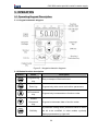
5.1 Operating Keypad Description ...............................................................................26
5.2 Operation Process.................................................................................................28
5.3 Running State........................................................................................................30
6. DETAILED FUNCTION DESCRIPTION............................................................................. 31
P0 Group--Basic Function ...........................................................................................31
P1 Group--Start and Stop Control ................................................................................37
P2 Group--Motor Parameters ......................................................................................41
P3 Group --PID Control ...............................................................................................42
P4 Group--V/F Control ................................................................................................48
P5 Group--Input Terminals...........................................................................................51
P6 Group -- Output Terminals ......................................................................................56
P7 Group--Display Interface ........................................................................................60
P8 Group--Water-supply Function ...............................................................................66
1
CHV160A series special inverter for water supply
P9 Group--Timing Watering and Multi-given Function Group........................................73
PA Group--Protection Parameters................................................................................75
Pb Group --Serial Communication ...............................................................................81
PC Group --Enhanced Function...................................................................................83
Pd Group--PID Enhanced Function .............................................................................87
PE Group—Factory Setting .........................................................................................88
7.
TROUBLE SHOOTINGT................................................................................................. 89
7.1 Fault and trouble shooting .....................................................................................89
7.2 Common Faults and Solutions ...............................................................................93
8. MAINTENANCE ................................................................................................................ 94
8.1 Daily Maintenance.................................................................................................94
8.2 Periodic Maintenance ............................................................................................95
8.3 Replacement of wearing parts ...............................................................................96
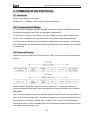
9. COMMUNICATION PROTOCOL ....................................................................................... 97
9.1 Interfaces ..............................................................................................................97
9.2 Communication Modes ..........................................................................................97
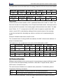
9.3 Protocol Format.....................................................................................................97
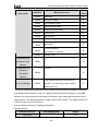
9.4 Protocol function....................................................................................................98
9.5 Note .................................................................................................................... 103
9.6 CRC Check ......................................................................................................... 103
9.7 Example.............................................................................................................. 103
10. DESCRIPTION OF WATERING EXTENSION CARD......................................................110
10.1 Description of Model .......................................................................................... 110
10.2 External Dimension ........................................................................................... 110
10.3 Installation ......................................................................................................... 110
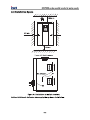
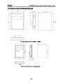
APPENDIX A RELATIVE DIMENSION OF INVERTER .........................................................111
A.1 External Dimension ............................................................................................. 111
A.2 Installation Space................................................................................................ 112
A.3 Dimensions of External Keypad........................................................................... 113
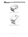
A.4 Disassembly ....................................................................................................... 114
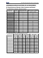
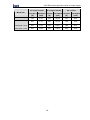
APPENDIX B SPECIFICATIONS OF ACCESSORIES ..........................................................115
B.1 Specifications of Breaker, Cable, Contactor and Reactor ..................................... 115
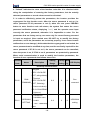
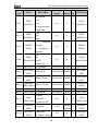
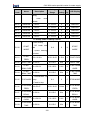
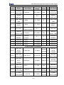
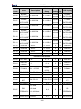
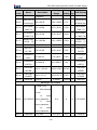
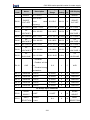
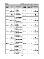
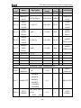
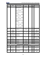
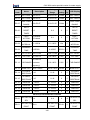
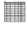
APPENDIX C FUNCTION PARAMETERS ...........................................................................117
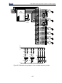
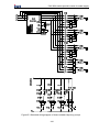
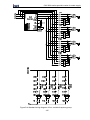
APPENDIX D WATERING STANDARD WIRING DIAGRAM................................................ 142
2
CHV160A series special inverter for water supply
1. INTRODUCTION
1.1 Technology Features
● Input & output
u Input voltage range: 380±15%
u Input frequency range: 47~63Hz
u Output voltage range: 0~rated input voltage
u Output frequency range: 0~400Hz
● I/O features
u Programmable digital input: Provide 8 inputs
u Programmable analog input: AI1 and AI2, which can accept 0~10V or 0~20mA.
u Relay output: Provide 3 output terminals. 8 outputs can be extended by
Water-supply extension card.
u Analog output: Provide 2 output terminal(0/4-20mA or 0/2-10V).
u Communication interface: standard RS485 serial port
● Main control function
u Control mode: V/F control.
u Overload capacity: 60s with 120% of rated current, 10s with 150% of rated current,
u Speed adjusting range: 1:100
u Carrier frequency: 1.0 kHz~16.0 kHz.
● Functions
u Frequency reference source: Digital input, analog input, PID Input,etc.
u DC braking at starting and stopping
u Sleep wake function.
u PID Control Function for water supply or other occasions
u Programmable digital input and output
u Skip frequency control function
u None-Stop when instantaneous power off.
u Speed Trace Function: Smoothly start the running motor.
u QUICK/JOG: User defined shortcut key can be realized.
u Automatic Voltage Regulation Function (AVR):
u Up to 26 fault protections: Protect from over current, over voltage, under voltage,
over temperature, phase failure, over load etc.
4
CHV160A series special inverter for water supply
1.2 Features of Water Supply System
u Support two kinds of water supply mode: fixed frequency pump mode and
circulating pump mode.
u Flexibility control logic to add, subtract pump.
u Up to eight segment pressure settings which change pressure given in different
time.
u 16 segment of the pressure given by different combination of input terminals.
u Sleep pump control functions: Support flexible sleep mode, the small sleep pump
will start automatically at sleep state in order to maintain sleep pressure effectively.
Once meeting the wake-up conditions, the system will come out of hibernation
automatically, and stop the small sleep pump.
u Regular rotation control, which can prevent the pump seizing by corrosion
effectively, and prevent one pump running all the time.
It is suggested that the
power of rotation pumps should be fairish, otherwise it will cause the system
pressure fluctuating.
u Sewage pump control functions, which is used to detect water level of cesspool
and control water level of cesspool.
u Inlet basin water-level detection and control functions, which can detect liquid level
of inlet basin, and adjust pressure-given automaticly.
u Ultra- voltage, under-voltage alarm function of pipe network, inverter supports
ultra- voltage, under-voltage alarm output functions, which can outputs through
programmable relay.
u Set up to motor rated current parameters of no less than seven pumps, and
achieve over-current, overload and other protection for the current pump-run.
u Record failure pump: Record failure pump automatically, and if cleared this record,
please use function of fault clearance.
u Provides standard RS485 Physics communication mode, using master-slave
communication though international standard Modbus communication protocol,
electrical parameters in full compliance with international standards, which can be
achieved barrier-free communication between CHV160A inverter special for water
supply system and the host computer.
5
CHV160A series special inverter for water supply
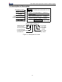
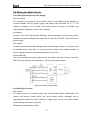
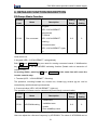
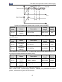
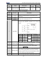
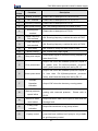
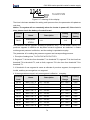
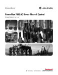
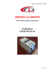
1.3 Description of Nameplate
Company name
SHENZHEN INVT ELECTRIC CO.,LTD.
Model number
MODEL: CHV160A-045G-4
Power
Input specification
INPUT: AC 3PH 380V±15%
SPEC:V2
POWER:45kW
Output specification
50/60Hz
OUTPUT: 90A AC 0~380V 0~400Hz
Bar code
Bar code
MADE IN CHINA
CHV160A-045G-4
Close loop vector
control inverter
The first generation
Input voltage
4: 3AC 380V
G: Constant
torque
Power rating
045: 45kW
0: Universal type
6: Only for water supply
A: Enhanced
Figure 1.1 Nameplate of inverter
6
CHV160A series special inverter for water supply
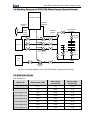
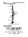
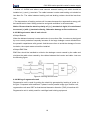
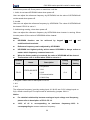
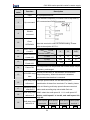
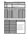
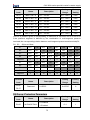
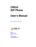
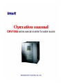
1.4 Working Diagram of CHV160A Water Supply Special Inverter
CHV160 Inverter
Pressure
feedback
Pressure
given
Water
level
control
Pressure
display
Ring shaped
network
Networ
1 for life
Intake sump
Networ 2
for life
Fixed frequency
pump or circulating
pump
Networ
for
industry
drained
water
Sewage
pump
Sewage
pump
Figure 1.2 Working diagram of the CHV160A water supply special inverter
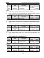
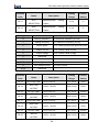
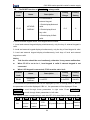
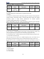
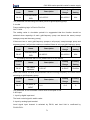
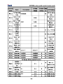
1.5 Selection Guide
3AC 380V±15%
Model No.
Rated power (kW)
CHV160A-5R5-4
5.5
CHV160A-7R5-4
7.5
Rated input
Rated output
current (A)
current (A)
15.0
13.0
20.0
17.0
CHV160A-011-4
11.0
26.0
25.0
CHV160A-015-4
15.0
35.0
32.0
CHV160A-018-4
18.5
38.0
37.0
CHV160A-022-4
22.0
46.0
45.0
CHV160A-030-4
30.0
62.0
60.0
CHV160A-037-4
37.0
76.0
75.0
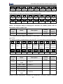
7
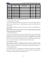
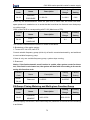
CHV160A series special inverter for water supply
Rated input
Rated output
current (A)
current (A)
90.0
90.0
55.0
105.0
110.0
CHV160A-075-4
75.0
140.0
150.0
CHV160A-090-4
90.0
160.0
176.0
CHV160A-110-4
110.0
210.0
210.0
CHV160A-132-4
132.0
240.0
250.0
Model No.
Rated power (kW)
CHV160A-045-4
45.0
CHV160A-055-4
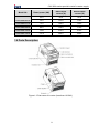
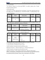
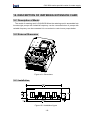
1.6 Parts Description
Figure 1.3 Part name of inverter (Less than 18.5kW)
8
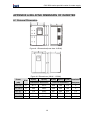
CHV160A series special inverter for water supply
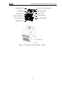
Keypad bracket
Cover the fixed hook mouth
Shield plate
Operating keypad
Control board
Functional card
Control terminal
Main circuit terminal
PG card expansion
Control cable inlet
Installation hole
Figure 1.4 Part name of inverter (22kW~132kW)
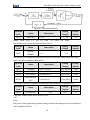
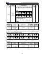
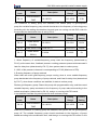
9
CHV160A series special inverter for water supply
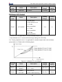
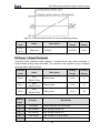
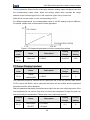
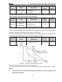
will be derated when the altitude is higher than 1000m. For details, please refer to the
following figure:
Iout
100%
80%
60%
40%
20%
1000
2000
3000
4000(m)
Figure 3.1 Relationship between output current and altitude
3.1.4 Impact and oscillation
It is not allowed that the inverter falls down or suffers from fierce impact or the inverter
installed at the place that oscillation frequently. The maximum swing should less than
2
5.8m/s (0.6g).
3.1.5 Electromagnetic radiation
Keep away from the electromagnetic radiation source.
3.1.6 Water
Do not install the inverter at the wringing or dewfall place.
3.1.7 Air pollution
Keep away from air pollution such as dusty, corrosive gas.
3.1.8 Storage
Do not store the inverter in the environment with direct sunlight, vapor, oil fog and
vibration.
12
CHV160A series special inverter for water supply
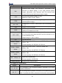
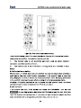
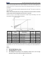
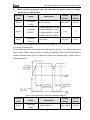
Figure 4.4 Main circuit terminals (22~132kW)
Main circuit terminal functions are summarized according to the terminal symbols in the
following table. Wire the terminal correctly for the desired purposes.
Terminal
Description
R、S、T
Terminals of 3 phase AC input
(+)、(-)
Spare terminals of external braking unit
(+)、PB
Spare terminals of external braking resistor
P1、(+)
Terminal of ground
(-)
Terminal of negative DC bus
U、V、W
Terminals of 3 phase AC output
Terminal of ground
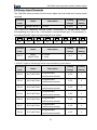
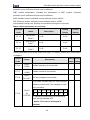
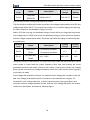
Control Circuit Terminals
+10V GND AI1
AI2 COM S1
PE GND AO1 AO2 24V
S2
S3
PW COM S7
S5
S4
S6
RO1A RO1B RO1C
S8 485+ 485-
RO2A RO2B RO2C
Figure 4.5 Control circuit terminals.
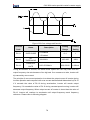
RT1A RT1B
RT2A RT2B
RT3A RT3B
RT4A RT4B
RT5A RT5B
RT6A RT6B
RT7A RT7B
RT8A RT8B
Figure 4.6 terminals on the water supply control card
15
RO3A RO3B
RO3C
CHV160A series special inverter for water supply
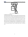
4.3 Typical Wiring Diagram
DCL DC External Braking Unit
(+) BR1
Reactor
Braking
(-) BR2
Resister
P1
Protect circuit
3 phase
380V±15%
50/60Hz
(+) (-)
U
R
S
V
+
T
Main circuit
Multifunctional on-off
input 1
S2
Multifunctional on-off
input 3
PE
CHV160A
control board
S1
Multifunctional on-off
input 2
Interface For
EXternal Keypad
CN8
S3
Multifunctional on-off
input 4
M
W
S4
Multifunctional on-off
input 5
Interface For
Water-supply Card
J5
S5
Multifunctional on-off
input 6
S6
S7
Multifunctional on-off
input 8
AO2
J12
S8
V
I
V
I
COM
PE
+24V connect to PW
+24V
AI1
AI2
0-10V input
0/4-20mA input
GND
{
Anolog Output
0-10V/0-20mA
V
V
I
I
RS485-
J9
GND
J11
RO3A
Jumper select I or V
PE
Relay output 1
GND
0-10V/0-20mA
RS485+
+10V
Frequency/PID
setting
AO1
J10
PW
Analog Output
GND
RO3B
RO1C
RO3C
RO1B
RO2A
RO1A
RO2B
RO2C
Figure 4.7 Wiring diagram.
16
{
{
Multifunctional on-off
input 7
Relay output 1
Relay output 2
CHV160A series special inverter for water supply
4.4 Wiring the Main Circuits
4.4.1 Wiring at the side of power supply
●Circuit breaker
It is necessary to connect a circuit breaker which is compatible with the capacity of
inverter between 3ph AC power supply and power input terminals (R, S, T). The
capacity of breaker is 1.5~2 times to the rated current of inverter. For details, see
<Specifications of Breaker, Cable, and Contactor.
●Contactor
In order to cut off the input power effectively when something is wrong in the system,
contactor should be installed at the input side to control the ON-OFF of the main circuit
power supply.
●AC reactor
In order to prevent the rectifier damage result from the large current, AC reactor should
be installed at the input side. It can also prevent rectifier from sudden variation of
power voltage or harmonic generated by phase-control load.
●Input EMC filter
The surrounding device may be disturbed by the cables when the inverter is working.
EMC filter can minimize the interference. Just like the following figure.
Figure 4.8 Wiring at input side.
4.4.2 Wiring for inverter
●DC reactor
DC reactor is built in CHV190 inverter from 18.5kW~90kW (380V classification) DC
reactor can improve power factor, can avoid bridge rectifier damaged due to
large-capacity transformer Ershi resulting in larger input current, can avoid rectifier
circuit damage caused by sinusoidal.
●Braking unit and braking resistor
17
CHV160A series special inverter for water supply
• Inverter of 18.5KW and above need connect external braking unit which should be
installed at (+) and (-) terminals. The cable between inverter and braking unit should be
less than 5m. The cable between braking unit and braking resistor should be less than
10m.
• The temperature of braking resistor will increase because the regenerative energy will
be transformed to heat. Safety protection and good ventilation is recommended.
Notice: Be sure that the electric polarity of (+) (-) terminals is right; it is not allowed
to connect (+) with (-) terminals directly, Otherwise damage or fire could occur.
4.4.3 Wiring at motor side of main circuit
●Output Reactor
When the distance between inverter and motor is more than 50m, inverter may be tripped
by over-current protection frequently because of the large leakage current resulted from
the parasitic capacitance with ground. And the same time to avoid the damage of motor
insulation, the output reactor should be installed.
●Output EMC filter
EMC filter should be installed to minimize the leakage current caused by the cable and
minimize the radio noise caused by the cables between the inverter and cable. Just see
the following figure.
Figure 4.9 Wiring at motor side.
4.4.4 Wiring of regenerative unit
Regenerative unit is used for putting the electricity generated by braking of motor to
the grid. Compared with traditional 3 phase inverse parallel bridge type rectifier unit,
regenerative unit uses IGBT so that the total harmonic distortion (THD) is less than 4%.
Regenerative unit is widely used for centrifugal and hoisting equipment.
18
CHV160A series special inverter for water supply
RST
Grid
Figure 4.10 Wiring of regenerative unit.
4.4.5 Wiring of Common DC bus
Common DC bus method is widely used in the paper industry and chemical fiber industry
which need multi-motor to coordinate. In these applications, some motors are in driving
status while some others are in regenerative braking (generating electricity) status. The
regenerated energy is automatically balanced through the common DC bus, which means
it can supply to motors in driving status. Therefore the power consumption of whole
system will be less compared with the traditional method (one inverter drives one motor).
When two motors are running at the same time (i.e. winding application), one is in driving
status and the other is in regenerative status. In this case the DC buses of these two
inverters can be connected in parallel so that the regenerated energy can be supplied to
motors in driving status whenever it needs. Its detailed wiring is shown in the following
figure:
19
CHV160A series special inverter for water supply
Figure 4.11 Wiring of common DC bus.
Notice: Two inverters must be the same model when connected with Common
DC bus method. Be sure they are powered on at the same time.
4.4.5 Ground Wiring (PE)
In order to ensure safety and prevent electrical shock and fire, terminal PE must be
grounded with ground resistance. The ground wire should be big and short, and it is
2
better to use copper wire (>3.5mm ). When multiple inverters need to be grounded, do
not loop the ground wire.
4.5 Wiring Control Circuit Terminals
4.5.1 Precautions
l
Use shielded or twisted-pair cables to connect control terminals.
l
Connect the ground terminal (PE) with shield wire.
The cable connected to the control terminal should leave away from the main circuit
and heavy current circuits (including power supply cable, motor cable, relay and
contactor connecting cable) at least 20cm and parallel wiring should be avoided. It is
suggested to apply perpendicular wiring to prevent inverter malfunction caused by
external interference.
4.5.2 Control circuit and extension card terminals
Terminal
S1~S8
Description
ON-OFF signal input, optical coupling with PW and COM.
Input voltage range: 9~30V
Input impedance: 3.3kΩ
20
CHV160A series special inverter for water supply
Terminal
Description
External power supply. +24V terminal is connected to PW
terminal as default setting. If user need external power
PW
supply, disconnect +24V terminal with PW terminal and
connect PW terminal with external power supply.
Provide output power supply of +24V.
+24V
Maximum output current: 150mA
Common ground terminal for digital signal and +24V (or
COM
external power supply).
Analog input, 0~10V/0~20mA which can be switched by J9
or J11.
AI1、AI2
+10V
Supply +10V for inverter.
Common ground terminal of analog signal and +10V.
GND
GND must isolated from COM.
Provide voltage or current output which AO1can be switched
by J10 on the control board and AO2 can be switched by J12
on the extension card.
AO1、AO2
Output range: 0~10V/ 0~20mA.
PE
Ground terminal.
RO1 relay output: RO2C—common; RO2B—NC;
RO2A—NO.
RO1A、RO1B、
RO1C
Contact capacity: AC 250V/3A, DC 30V/1A.
RO2 relay output: RO2C—common; RO2B—NC;
RO2A—NO.
RO2A、RO2B、
RO2C
Contact capacity: AC 250V/3A, DC 30V/1A.
RO3 relay output: RO3C—common; RO3B—NC;
RO3A—NO.
RO3A、RO3B、
RO3C
Contact capacity: AC 250V/3A, DC 30V/1A.
RT1~RT8(A、B)
RS485+,RS485-
Eight relay outputs (NO),
Contact capacity: AC250V/5A
RS485 serial communication
4.5.3 Jumper on control board
Jumper
J1、J3、J4
J6、J7
Description
It is prohibited to be connected together, otherwise it will cause
inverter malfunction.
Do not change factory default connection of J6J(marked with ATX)
and J7 (marked with ARX), otherwise it will cause communication
21
CHV160A series special inverter for water supply
Jumper
Description
malfunction.
Switch between (0~10V) voltage input and (0~20mA) current
input.
J9、J11
V connect to GND means voltage input;
I connect to GND means current input.
J9 is the jumper of AI1; J11 is the jumper of AI2
Switch between (0~10V) voltage output and (0~20mA) current
output.
J10、J12
V connect to OUT means voltage output;
I connect to OUT means current output.
J10 is the jumper of AO1; J12 is the jumper of AO2
4.6 Installation Guidline to EMC Compliance
4. 6.1 General knowledge of EMC
EMC is the abbreviation of electromagnetic compatibility, which means the device or
system has the ability to work normally in the electromagnetic environment and will not
generate any electromagnetic interference to other equipments.
EMC
includes
two subjects:
electromagnetic
interference and
electromagnetic
anti-jamming.
According to the transmission mode, Electromagnetic interference can be divided into two
categories: conducted interference and radiated interference.
Conducted interference is the interference transmitted by conductor. Therefore, any
conductors (such as wire, transmission line, inductor, capacitor and so on) are the
transmission channels of the interference.
Radiated interference is the interference transmitted in electromagnetic wave, and the
energy is inverse proportional to the square of distance.
Three necessary conditions or essentials of electromagnetic interference are:
interference source, transmission channel and sensitive receiver. For customers, the
solution of EMC problem is mainly in transmission channel because of the device
attribute of disturbance source and receiver can not be changed.
4.6.2 EMC features of inverter
Like other electric or electronic devices, inverter is not only an electromagnetic
interference source but also an electromagnetic receiver. The operating principle of
inverter determines that it can produce certain electromagnetic interference noise. And
22
CHV160A series special inverter for water supply
the same time inverter should be designed with certain anti-jamming ability to ensure the
smooth working in certain electromagnetic environment. The following is its EMC
features:
l
Input current is non-sine wave. The input current includes large amount of
high-harmonic waves that can cause electromagnetic interference, decrease the grid
power factor and increase the line loss.
l
Output voltage is high frequency PMW wave, which can increase the temperature
rise and shorten the life of motor. And the leakage current will also increase, which can
lead to the leakage protection device malfunction and generate strong electromagnetic
interference to influence the reliability of other electric devices.
l
As the electromagnetic receiver, too strong interference will damage the inverter
and influence the normal using of customers.
l
In the system, EMS and EMI of inverter coexist. Decrease the EMI of inverter can
increase its EMS ability.
4.6.3 EMC Installation Guideline
In order to ensure all electric devices in the same system to work smoothly, this section,
based on EMC features of inverter, introduces EMC installation process in several
aspects of application (noise control, site wiring, grounding, leakage current and power
supply filter). The good effective of EMC will depend on the good effective of all of these
five aspects.
4.6.3.1 Noise control
All the connections to the control terminals must use shielded wire. And the shield layer of
the wire must ground near the wire entrance of inverter. The ground mode is 360 degree
annular connection formed by cable clips. It is strictly prohibitive to connect the twisted
shielding layer to the ground of inverter, which greatly decreases or loses the shielding
effect.
Connect inverter and motor with the shielded wire or the separated cable tray. One side
of shield layer of shielded wire or metal cover of separated cable tray should connect to
ground, and the other side should connect to the motor cover. Installing an EMC filter can
reduce the electromagnetic noise greatly.
4.6.3.2 Site wiring
Power supply wiring: the power should be separated supplied from electrical transformer.
Normally it is 5 core wires, three of which are fire wires, one of which is the neutral wire,
and one of which is the ground wire. It is strictly prohibitive to use the same line to be both
the neutral wire and the ground wire
23
CHV160A series special inverter for water supply
Device categorization: there are different electric devices contained in one control cabinet,
such as inverter, filter, PLC and instrument etc, which have different ability of emitting and
withstanding electromagnetic noise. Therefore, it needs to categorize these devices into
strong noise device and noise sensitive device. The same kinds of device should be
placed in the same area, and the distance between devices of different category should
be more than 20cm.
Wire Arrangement inside the control cabinet: there are signal wire (light current) and
power cable (strong current) in one cabinet. For the inverter, the power cables are
categorized into input cable and output cable. Signal wires can be easily disturbed by
power cables to make the equipment malfunction. Therefore when wiring, signal cables
and power cables should be arranged in different area. It is strictly prohibitive to arrange
them in parallel or interlacement at a close distance (less than 20cm) or tie them together.
If the signal wires have to cross the power cables, they should be arranged in 90 angles.
Power input and output cables should not either be arranged in interlacement or tied
together, especially when installed the EMC filter. Otherwise the distributed capacitances
of its input and output power cable can be coupling each other to make the EMC filter out
of function.
4.6.3.3 Ground
Inverter must be ground safely when in operation. Grounding enjoys priority in all EMC
methods because it does not only ensure the safety of equipment and persons, but also is
the simplest, most effective and lowest cost solution for EMC problems.
Grounding has three categories: special pole grounding, common pole grounding and
series-wound grounding. Different control system should use special pole grounding, and
different devices in the same control system should use common pole grounding, and
different devices connected by same power cable should use series-wound grounding.
4.6.3.2 Leakage current
Leakage current includes line-to-line leakage current and over-ground leakage current.
Its value depends on distributed capacitances and carrier frequency of inverter. The
over-ground leakage current, which is the current passing through the common ground
wire, can not only flow into inverter system but also other devices. It also can make
leakage current circuit breaker, relay or other devices malfunction. The value of
line-to-line leakage current, which means the leakage current passing through distributed
capacitors of input output wire, depends on the carrier frequency of inverter, the length
and section areas of motor cables. The higher carrier frequency of inverter, the longer of
the motor cable and/or the bigger cable section area, the larger leakage current will
24
CHV160A series special inverter for water supply
occur.
Countermeasure:
Decreasing the carrier frequency can effectively decrease the leakage current. In the
case of motor cable is relatively long (longer than 50m), it is necessary to install AC
reactor or sinusoidal wave filter at the output side, and when it is even longer, it is
necessary to install one reactor at every certain distance.
4.6.3.5 EMC Filter
EMC filter has a great effect of electromagnetic decoupling, so it is preferred for customer
to install it.
For inverter, noise filter has following categories:
l
Noise filter installed at the input side of inverter;
l
Install noise isolation for other equipment by means of isolation transformer or
power filter.
4.6.4 If user install inverter and EMI filter according to the installation guideline, we
believe inverter system comply with following compliance.
l
EN61000-6-4
l
EN61000-6-3
l
EN61800-3
4.6.5 Notice
l
This type of PDS is not intended to be used on a low-voltage public
network which supplies domestic premise;
l
Radio frequency interference is expected if used on such a network.
25
CHV160A series special inverter for water supply
5. OPERATION
5.1 Operating Keypad Description
5.1.1 Keypad schematic diagram
Figure 5.1 Keypad schematic diagrams.
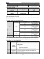
5.1.2 Button function description
Button
Name
Programming
Key
Enter Key
UP Increment
Key
Description
Entry or escape of first-level menu.
Progressively enter menu and confirm parameters.
Progressively increase data or function codes.
DOWN
Decrement
Progressive decrease data or function codes.
Key
In parameter setting mode, press this button to select
Shift Key
the bit to be modified. In other modes, cyclically
displays parameters by right shift
26
CHV160A series special inverter for water supply
Button
Name
Run Key
Description
Start to run the inverter in keypad control mode.
In running status, restricted by P7.04, can be used to
STOP/RESET
Key
stop the inverter.
When fault alarm, can be used to reset the inverter
without any restriction.
Determined by Function Code P7.03:
0: Jog operation
1: Switch between forward and reverse
Shortcut Key
2: Clear the UP/DOWN settings.
3: Quick debugging mode1 (by menu)
4: Quick debugging mode2 (by latest order)
5: Quick debugging mode3 (by non-factory setting
parameters)
Combination
+
Key
Pressing the RUN and STOP/RST at the same time
can achieve inverter coast to stop.
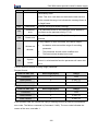
5.1.3 Indicator light description
5.1.3.1 Function indicator light description
Function indicator
Description
Extinguished: stop status
RUN/TUNE
Flickering: parameter autotuning status
Light on: operating status
FWD/REV
Extinguished: forward operation
Light on: reverse operation.
Extinguished: keypad control
LOCAL/REMOT
Flickering: terminal control
Light on: communication control
TRIP
Extinguished: normal operation status
Flickering: overload pre-warning status
5.1.3.2 Unit Indicator light description
27
CHV160A series special inverter for water supply
Function indicator
Description
Hz
Frequency unit
A
Current unit
V
Voltage unit
RPM
Rotating speed unit
%
Percentage
5.1.3.3 Digital display
Have 5 digit LED , which can display all kinds of monitoring data and alarm codes such
as reference frequency, output frequency and so on.
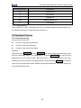
5.2 Operation Process
5.2.1 Parameter setting
Three levels of menu are:
l
Function code group (first-level);
l
Function code (second-level);
l
Function code value (third-level).
Remarks:
Press both the PRG/ESC and the DATA/ENT can return to the second-class menu
from the third-class menu. The difference is: pressing DATA/ENT will save the set
parameters into the control panel, and then return to the second-class menu with
shifting to the next function code automatically; while pressing PRG/ESC will directly
return to the second-class menu without saving the parameters, and keep staying at
the current function code.
28
CHV160A series special inverter for water supply
5.2.4 Parameter copy
For details, please refer to the instructions of LCD keyboard functions
5.2.5 Password Settings:
CHV160A series inverter provides user password protection function. When P7.00 is
zero, which is user’s password, quitting code editing state can make password
protection effective, then pressing PRG/ESC can enter code editing state, "-----" will
be showed. Operator must enter a correct.
To cancel password protection function, setting P7.00 to be zero is ok. User's
password has no protection to the parameter on shortcut menu.
5.3 Running State
5.3.1 Power-on initialization
Firstly the system initializes during the inverter power-on, and LED displays “8888”. After
the initialization is completed, the inverter is on stand-by status.
5.3.2 Stand-by
At stop or running status, parameters of multi-status can be displayed. Whether or not to
display this parameter can be chosen through Function Code P7.06 (Running status
display selection) and P7.07 (Stop status display selection) according to binary bits, the
detailed description of each bit please refer to the function code description of P7.06 and
P7.07.
In stop status, there are sixteen parameters which can be chosen to display or not. They
are: reference frequency, DC bus voltage, PID setting, PID feedback, input terminal
status, output terminal status, analog AI1, analog AI2, and some reserved parameters.
Whether or not to display can be determined by setting the corresponding binary bit of
P7.07. Press the 》/SHIFT to scroll through the parameters in right order.
5.3.3 Operation
In running status, there are twenty one running parameters which can be chosen to
display or not. They are: running frequency, reference frequency, DC bus voltage, output
voltage, output current, rotating speed, output power, PID setting, PID feedback, input
terminal status, output terminal status, analog AI1, analog AI2 and some reserved
parameters. Whether or not to display can be determined by setting the corresponding
binary bit of P7.06. Press the 》/SHIFT to scroll through the parameters in right order .
5.3.4 Fault
In fault status, inverter will display parameters of STOP status besides parameters of fault
status. Press the 》/SHIFT to scroll through the parameters in right order.
30
CHV160A series special inverter for water supply
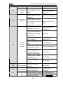
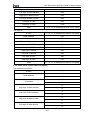
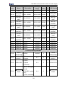
6. DETAILED FUNCTION DESCRIPTION
P0 Group--Basic Function
Function
Name
Code
Description
Setting
Factory
Range
Setting
0~2
0
0:Keypad
(LED–“LOCAL/REMOT”,
extinguished)
1:Terminal
P0.00
Run command
(LED–“LOCAL/REMOT”,
flickering)
2:Communication
(LED–“LOCAL/REMOT”,lights
on)
The control commands of inverter include: start, stop, forward run, reverse run, jog, fault
reset and so on.
0: Keypad (LED—“LOCAL/REMOT”, extinguished);
Both RUN and STOP/RST key are used for running command control. If Multifunction
key QUICK/JOG is set as FWD/REV switching function (Details refer to instruction of
CODE P7.03).
In running status, pressing RUN and STOP/RST in the same time will cause the
inverter coast to stop.
1: Terminal (LED –“LOCAL/REMOT”, flickering)
The operation, including forward run, reverse run, forward jog, reverse jog etc. can be
controlled by multifunctional input terminals.
2: Communication (LED–“LOCAL/REMOT”, lights on)
The operation of inverter can be controlled by host through communication.
Function
Code
Name
Description
Setting
Factory
Range
Setting
0~2
0
0: Valid&Save
P0.01
UP/DOWN setting
1: Valid&Not save
2: Invalid
3: Run valid&Stop reset
0: Valid, save UP/DOWN value when power off.
User can adjust the reference frequency by UP/DOWN. The value of UP/DOWN can be
31
CHV160A series special inverter for water supply
saved when power off, Once power on next time, it will be.
1: Valid, do not save UP/DOWN value when power off.
User can adjust the reference frequency by UP/DOWN, but the value of UP/DOWN will
not be saved when power off.
2: Invalid.
User can not adjust the reference frequency by UP/DOWN. The value of UP/DOWN will
be cleared if P0.02 is set to 2.
3: Valid during running, clear when power off
User can adjust the reference frequency by UP/DOWN when inverter is running. When
inverter power off, the value of UP/DOWN will be cleared
Notice:
UP/DOWN function can be achieved by keypad (∧
l
and
∨ ) and
multifunctional terminals.
l
Reference frequency can be adjusted by UP/DOWN.
l
UP/DOWN has highest priority which means UP/DOWN is always active no
matter which frequency command source is.
l
When the factory setting is restored, the value of UP/DOWN will be cleared.
l
The function code is invalid when P8.00 is set to be 1.
Function
Name
Code
Description
Setting
Factory
Range
Setting
0~4
0
0: Keyboard
P0.02
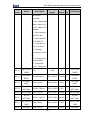
FREQ SOURCE
A
1: AI1
2. AI2
3. Communication
4: Multi-Step
0: Keypad: Please refer to description of P0.09.
1: AI1
2: AI2
The reference frequency is set by analog input. AI1 & AI2 are 0-10V voltage inputs or
0(4) ~20mA current input.The input mode is switched by jumpers J9&J11.
Notice:
l
For detailed relationship between analogue input voltage and frequency,
please refer to description of P5.12~P5.16.
l
100%
of
AI
is
corresponding
to
maximum
correspongding to reverse maximum frequency.
32
frequency,-100%
is
CHV160A series special inverter for water supply
3: Communication
The reference frequency is set through RS485. For details, please refer to Capter
9-Communication protocol.
4:Multi-steps speed
The selection of steps is determined by combination of multi-step speed terminals,and
the setting value
is determined by
P9.18~P9.33,100%- is corresponding to the
maximum frequency.
Function
Code
P0.03
Name
FREQ SOURCE
B
Description
Setting
Factory
Range
Setting
0~2
0
0:AI1
1:AI2
2:PID
When Frequency B command acts as the independent reference frequency source. The
function is the same with that of frequency A command.
Function
Code
P0.04
Name
FREQ B SCALE
Description
0: Maximum frequency
1: Frequency A command
Setting
Factory
Range
Setting
0~1
0
0: reference frequency B = AI1 (%) * P0.04 (maximum frequency).
1: reference frequency B = AI1 (%) * reference frequency A.
Function
Code
Name
Description
Setting
Factory
Range
Setting
0~3
0
0: A
P0.05
FREQ
SELECTION
1: B
2: A+B
3: Max(A, B)
This parameter can be used to select the reference frequency command.
0: Only frequency command source A is active.
1: Only Frequency command source B is active.
2: Both Frequency command source A and B are active.
Reference frequency = reference frequency A + reference frequency B.
3: Both Frequency command source A and B are active.
Reference frequency = Max (reference frequency A, reference frequency B).
Notice: The frequency command source can be selected not only P0.05 but also
by multifunctional terminals. Please refer to description of P5 Group.
33
CHV160A series special inverter for water supply
Function
Code
P0.06
Name
Max FREQ
Description
10~400.00Hz
Setting
Factory
Range
Setting
10.0~400.0
0
50.00Hz
Notice:
l
The frequency reference should not exceed maximum frequency.
l
Actual acceleration time and deceleration time are determined by maximum
frequency. Please refer to description of P0.10 and P0.11.
Function
Code
P0.07
Name
UP FREQ LIMIT
Description
P0.08~P0.06
Setting
Factory
Range
Setting
P0.08~P0.06
50.00Hz
Notice:
Upper frequency limit should not be greater than the maximum frequency
l
(P0.07).
Output frequency should not exceed upper frequency limit.
l
Function
Code
P0.08
Name
LOW FREQ
LIMIT
Description
0.00Hz~ P0.08
Setting
Factory
Range
Setting
0.00~P0.08
0.00Hz
Notice:
l
Lower frequency limit should not be greater than upper frequency limit
(P0.07).
l
If frequency reference is lower than P0.09, the action of inverter is determined
by P1.11. Please refer to description of P1.11.
Function
Code
P0.09
Name
KEYPAD REF
FREQ
Description
0.00 Hz ~ P0.08
Setting
Factory
Range
Setting
0.00~P0.08
50.00Hz
When P0.02 is set to be 0, this parameter is the initial value of inverter reference
frequency.
Function
Code
Name
Description
Setting
Factory
Range
Setting
P0.10
ACC TIME
0.0~3600.0s
0.0~3600.0
20.0s
P0.11
DEC TIME
0.0~3600.0s
0.0~3600.0
20.0s
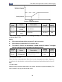
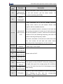
Acceleration time is the time of accelerating from 0Hz to maximum frequency (P0.06).
34
CHV160A series special inverter for water supply
Deceleration time is the time of decelerating from maximum frequency (P0.06) to 0Hz.
Please refer to following figure.
Figure 6.1 Acceleration and Deceleration time.
When the reference frequency is equal to the maximum frequency, the actual
acceleration and deceleration time will be equal to the P0.10 and P0.11 respectively.
When the reference frequency is less than the maximum frequency, the actual
acceleration and deceleration time will be less than the P0.10 and P0.11 respectively.
The actual acceleration (deceleration) time = P0.10 (P0.11) * reference frequency/P0.06.
Function
Code
Name
Description
Setting
Factory
Range
Setting
0~2
0
0: Default
P0.12
RUN DIRECTION
1: Reverse
2: Forbid reverse
Notice:
l
The rotation direction of motor is corresponding to the wiring of motor.
l
When the factory setting is restored, the rotation direction of motor may be
changed. Please be cautious to use.
l
If P0.12 is set to 2, user can not change rotation direction of motor by
QUICK/JOG or terminal.
Function
Code
P0.13
Name
CARRIER
FREQ
Description
1~16.0kHz
35
Setting
Range
1~16.0kHz
Factory
Setting
Depend
on model
CHV160A series special inverter for water supply
Figure 6.2 Effect of carrier frequency.
Carrier frequency
Highest Carrier
Lowest Carrier
Factory
Frequency(kHz)
Frequency(kHz)
Setting(kHz)
G Model: 4~15kW
16
1
6
G Model: 18.5kW
8
1
2
Model
Carrier frequency will affect the noise of motor and the EMI of inverter.
If the carrier frequency is increased, it will cause better current wave, less harmonic
current and lower noise of motor.
Notice:
l
The factory setting is optimal in most cases. Modification of this parameter is
not recommended.
l
If the carrier frequency exceeds the factory setting, the inverter must be
derated because the higher carrier frequency will cause more switching loss,
higher
temperature
rise
of
inverter
and
stronger
electromagnetic
interference.
l
If the carrier frequency is lower than the factory setting, it is possible to
cause less output torque of motor and more harmonic current.
Function
Code
P0.14
Name
RESTORE
PARA
Description
Setting
Factory
Range
Setting
0~2
0
0: No action
1: Restore factory setting
2: Clear fault records
0: No action
1: Inverter restores all parameters to factory setting except P2 group.
2: Inverter clear all fault records.
36
CHV160A series special inverter for water supply
This function code will restore to 0 automatically when complete the function
operation,and P2 group will not restore.
Function
Code
P0.15~
P0.19
Name
Reserved
Description
0~65535
Setting
Factory
Range
Setting
0~65535
0
Setting
Factory
Range
Setting
0~2
0
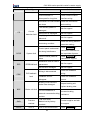
P1 Group--Start and Stop Control
Function
Code
Name
Description
0: Start directly
P1.00
START MODE
1: DC break and start
2: Speed tracking and
start
0: Start directly: Start the motor at the starting frequency determined by P1.01.
1: DC braking and start: Inverter will output DC current firstly and then start the motor
at the starting frequency. Please refer to description of P1.03 and P1.04. It is suitable
for the motor which have small inertia load and may reverse rotation when start.
2: Speed tracking and start: Inverter detects the rotation speed and direction of motor,
then start running to its reference frequency based on current speed. This can realize
smooth start of rotating motor with big inertia load when instantaneous power off.
Function
Code
Name
P1.01
START FREQ
P1.02
HOLD TIME
Description
0.00~10.0Hz
0.0~50.0s
Setting
Factory
Range
Setting
0.00~10.00
1.5Hz
0.0~50.0
0.0s
Notice:
l
Set proper starting frequency can increase the starting torque.
l
If the reference frequency is less than starting frequency, inverter will be at
stand-by status. The indicator of RUN/TUNE lights on, inverter has no output.
l
The starting frequency could be less than the lower frequency limits (P0.08).
l
P1.01 and P1.02 take no effect during FWD/REV switching.
37
CHV160A series special inverter for water supply
Figure 6.3 Starting diagram.
Function
Code
P1.03
P1.04
Name
START BRAK
CURR
START BRAK
TIME
Setting
Factory
Range
Setting
0.0~150.0%
0.0~150.0
0.0%
0.0~50.0s
0.0~50.0
0.0s
Description
When inverter starts, it performs DC braking according to P1.03 firstly, then start to
accelerate after P1.04.
Notice:
l
DC braking will take effect only when P1.00 is set to be 1.
l
DC braking is invalid when P1.04 is set to be 0.
l
The value of P1.03 is the percentage of rated current of inverter. The bigger
the DC braking current, the greater the braking torques.
Function
Code
P1.05
Name
STOP MODE
Description
0: Deceleration to stop
1: Coast to stop
Setting
Factory
Range
Setting
0~1
0
0: Deceleration to stop
When the stop command takes effect, the inverter decreases the output frequency
according to the deceleration mode and the selected acceleration/deceleration time till
stop.
1: Coast to stop
When the stop command takes effect, the inverter blocks the output immediately. The
motor coasts to stop by its mechanical inertia.
38
CHV160A series special inverter for water supply
Function
Code
P1.06
P1.07
P1.08
P1.09
Setting
Factory
Range
Setting
0.00~10.00
0.00Hz
0.0~50.0s
0.0~50.0
0.0s
0.0~150.0%
0.0~150.0
0.0%
0.0~50.0s
0.0~50.0
0.0s
Name
STOP BRAK
FREQ
STOP BRAK
DELAY
STOP BRAK
CURR
STOP BRAK
TIME
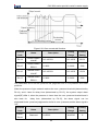
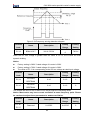
Description
0.00~P0.07
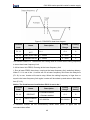
Starting frequency of DC braking: Start the DC braking when running frequency reaches
starting frequency determined by P1.06.
Waiting time before DC braking: Inverter blocks the output before starting the DC braking.
After this waiting time, the DC braking will be started. It is used to prevent over-current
fault caused by DC braking at high speed.
DC braking current: The value of P1.08 is the percentage of rated current of inverter. The
bigger the DC braking current, the greater the braking torque.
DC braking time: The time used to perform DC braking. If the time is 0, the DC braking
will be invalid.
Figure 6.4 DC braking diagram.
Function
Code
P1.10
Name
FWD/REV
DEADTIME
Description
0.0~3600.0s
Setting
Factory
Range
Setting
0.0~3600.0
0.0s
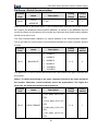
Set the hold time at zero frequency in the transition between forward and reverse
running.
It is shown as following figure:
39
CHV160A series special inverter for water supply
Figure 6.5 FWD/REV dead time diagram.
Function
Code
P1.11
Name
UNDER LIMIT
ACT
Description
0~1
Setting
Factory
Range
Setting
0~1
0
P1.12
LIMIT RUN TIME
0~3600s
0~3600
5
P1.13
AWOKE DELAY
0~3600s
0~3600
5
The function code of P1.11determine the running state of inverter when setting frequency
is lower than lower frequency limit.
0: UN at lower limit FREQ, Running at the lower frequency limit
1: Run at lower FREQ, then sleep, running at the lower frequency limit, and sleep latency.
When P1.11 is set to be 1, inverter will run at lower frequency limit.Once the delay time
(P1.12) is over, inverter will coast to stop; When the setting frequency is higer than or
equal to the lower frequency limit again, inverter will be waked up and autorun after delay
time (P1.13).
Notice: The functions are invalid when P8.00 is set to be 1.
Function
Code
P1.14
P1.15
Name
RESTART
RESTR DELAY
TIME
Description
0: Restart disabled
1: Restart enabled
0.0~3600.0s
Setting
Factory
Range
Setting
0~1
0
0.0~3600.0
0.0s
0: Disabled: Inverter will not automatically restart when power on again until run
command takes effect.
40
CHV160A series special inverter for water supply
1: Enabled: When inverter is running, after power off and power on again, if run command
source is keypad control (P0.00=0) or communication control (P0.00=2), inverter will
automatically restart after delay time determined by P1.15; if run command source is
terminal control (P0.00=1), inverter will automatically restart after delay time determined
by P1.15 only if FWD or REV is active.
Function
Name
Code
P1.16
Description
FWD/REV
0: Disabled
ENABLE
1: Enabled
Setting
Factory
Range
Setting
0~1
0
Notice:
l
This function only takes effect if run command source is terminal control.
l
If P1.16 is set to be 0, when power on, inverter will not start even if FWD/REV
terminal is active, until FWD/REV terminal disabled and enabled again.
l
If P1.16 is set to be 1, when power on and FWD/REV terminal is active,
inverter will start automatically.
l
This function may cause the inverter restart automatically, please be
cautious.
Function
Code
P1.17~
P1.19
Name
Reserved
Description
0~65535
Setting
Factory
Range
Setting
0~65535
0
Setting
Factory
P2 Group--Motor Parameters
Function
Code
P2.00
P2.01
P2.02
P2.03
P2.04
Name
MOTOR RATE
POWER
MOTOR RATE
FREQ
MOTOR RATE
SPEED
MOTOR RATE
VOLT
MOTOR RATE
CURR
Description
Range
Setting
Depend
1.5~900.0kW
1.5~900.0
0.01Hz~P0.07
0.01~P0.07
50.00Hz
0~36000rpm
0~36000
1460rpm
0~3000V
0~3000
380V
0.1~2000.0A
41
0.1~2000.0
on model
Depend
on model
CHV160A series special inverter for water supply
Notice: Please set the parameters according to the nameplate of motor.
Function
Name
Code
P2.05
P2.06
P2.07
P2.08
P2.09
P2.10
P2.11
A PUMP RATE
CURR
B PUMP RATE
CURR
C PUMP RATE
CURR
D PUMP RATE
CURR
E PUMP RATE
CURR
F PUMP RATE
CURR
G PUMP RATE
CURR
Description
Setting
Factory
Range
Setting
0.1~2000.0A
0.1~2000.0
0.1~2000.0A
0.1~2000.0
0.1~2000.0A
0.1~2000.0
0.1~2000.0A
0.1~2000.0
0.1~2000.0A
0.1~2000.0
0.1~2000.0A
0.1~2000.0
0.1~2000.0A
0.1~2000.0
Depend
on model
Depend
on model
Depend
on model
Depend
on model
Depend
on model
Depend
on model
Depend
on model
The above parameter is corresponding to the motor rated current of each pump, so
please set by the motor nameplates.These parameters can effect
the overload
protection of motor.
Function
Code
P2.12~P2.15
Name
Reserved
Description
0~65535
Setting
Factory
Range
Setting
0~65535
0
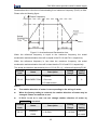
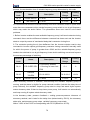
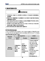
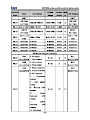
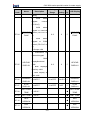
P3 Group --PID Control
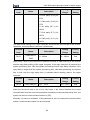
PID control is a common used method in process control, such as flow, pressure and
temperature control. The principle is firstly detecting the bias between preset value and
feedback value, then calculate output frequency of inverter according to proportional gain,
integral and differential time. Please refer to following figure.
42
CHV160A series special inverter for water supply
Figure 6.6 PID control diagram.
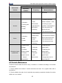
Function
Code
P3.00
0:MPa 1:kPa
Name
UNIT SEL
2:Pa
3:℃
Description
Setting
Factory
Range
Setting
0~10
0
0~10
4:A 5:V
6:Hz
7:% 8:rpm
9:h
10:kh
The function is to confirm the units of P3.02~P3.05.Function
Code
P3.01
Name
DISPLAY
FORMAT
Description
0~4
Setting
Factory
Range
Setting
0~4
3
The function is to display the radix point numbers of maximum value, upper limit value,
lower limit value, feedback value of PID.
Function
Code
Name
Factory
Range
Setting
0.001~65.535
1.000
PID UPPER
P3.04~P3.02
P3.04~P3.02
1.000
PID LOWER
P0.000~P3.03
P0.00~P3.03
0.100
P3.04~P3.03
P3.04~P3.03
0.500
PID MAX
P3.03
P3.05
Setting
0.001~65.535
P3.02
P3.04
Description
KEYPAD PID
SET
The unit and radix point numbers of parameters are decided by P3.00 and P3.01.
Function
Code
P3.06
Name
Description
PID PRESET
0~5
Setting
Factory
Range
Setting
0~5
0
0: Keypad: Please refers to the value of P3.05.
1:AI1
2:AI2
PID given is set by the analog, and the setting is similar with analog input of P0.02.But the
unit is decided by P3.00.
43
CHV160A series special inverter for water supply
3: Modbus
The reference frequency is set through RS485. For details, please refer to operation
manual of communication card.
4: Time water supply
The function parameter is determined by P9.01~P9.17.
5: Multi-press set
PID given is confirmed by the combination of - terminals status (P5 group) and
P9.18~P9.33.
When the frequency source is set to be PID or P8.00 = 1(water-supply function is valid),
the function will be valid. When the - target value of - PID is a relative percentage, -100%
is corresponding to P3.02 (maximum value of PID).
Function
Code
Name
Description
Setting
Factory
Range
Setting
0~3
0
0: AI1 feed
P3.07
PID FEEDBACK
1: AI2 feed
2: AI1-AI2 feed
3: Modbus feed
This parameter is used to select PID feedback source.
Notice:
l
Given value and feedback value of PID is percentage value.
l
100% of given value is corresponding to 100% of feedback value.
l
Given source and feedback source must not be same, otherwise PID will
be malfunction.
Function
Code
P3.08
Name
PID OUTPUT
Description
0: Positive
1: Negative
Setting
Factory
Range
Setting
0~1
0
0: Positive. When the feedback value is greater than the given value, output frequency
will be decreased, such as tension control in winding application.
1: Negative. When the feedback value is greater than the given value, output
frequency will be increased, such as tension control in unwinding application.
Function
Code
P3.09
Name
PROPORTION
GAIN (Kp)
Description
0.00~100.00
44
Setting
Factory
Range
Setting
0.00~100.00
0.10
CHV160A series special inverter for water supply
Function
Code
P3.10
P3.11
Setting
Factory
Range
Setting
0.01~10.00s
0.01~10.00
0.10s
0.00~10.00s
0.00~10.00
0.00s
Name
INTEGRAL
TIME (Ti)
DIFFERENTIA
TIME (Td)
Description
Optimize the responsiveness by adjusting these parameters while driving an actual
load.
Adjusting PID control:
Use the following procedure to activate PID control and then adjust it while monitoring
the response.
1.
Enabled PID control (P0.03=2)
2.
Increase the proportional gain (Kp) as far as possible without creating oscillation.
3.
Reduce the integral time (Ti) as far as possible without creating oscillation.
4.
Increase the differential time (Td) as far as possible without creating oscillation.
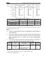
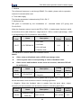
Making fine adjustments:
First set the individual PID control constants, and then make fine adjustments.
l
Reducing overshooting
If overshooting occurs, shorten the differential time and lengthen the integral time.
Figure 6.7 Reducing overshooting diagram.
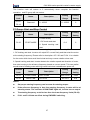
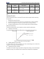
l
Rapidly stabilizing control status
To rapidly stabilize the control conditions even when overshooting occurs, shorten the
integral time and lengthen the differential time.
l
Reducing long-cycle oscillation
If oscillation occurs with a longer cycle than the integral time setting, it means that integral
operation is strong. The oscillation will be reduced as the integral time is lengthened.
45
CHV160A series special inverter for water supply
Figure 6.8 Reducing long-cycle oscillation diagram.
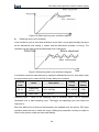
l
Reducing short-cycle oscillation
If the oscillation cycle is short and oscillation occurs with a cycle approximately the same
as the differential time setting, it means that the differential operation is strong. The
oscillation will be reduced as the differential time is shortened.
Figure 6.9 Reducing short-cycle oscillation diagram.
If oscillation cannot be reduced even by setting the differential time to 0, then either lower
the proportional gain or raise the PID primary delay time constant.
Function
Code
P3.12
P3.13
Name
Description
SAMPLING
CYCLE
(T)
BIAS LIMIT
0.01~100.00s
0.0~100.0%
Setting
Factory
Range
Setting
0.01~100.00
0.50s
0.0~100.0
0.0%
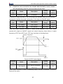
Sampling cycle T refers to the sampling cycle of feedback value. The PI regulator
calculates once in each sampling cycle. The bigger the sampling cycle, the slower the
response is.
Bias limit defines the maximum bias between the feedback and the preset. PID stops
operation when the bias is within this range. Setting this parameter correctly is helpful to
improve the system output accuracy and stability.
46
CHV160A series special inverter for water supply
Figure 6.10 Relationship between bias limit and output frequency.
Function
Code
P3.14
Name
OUTPUT
FILTER
Description
0.00~10.00s
Setting
Factory
Range
Setting
0.00~10.00
0.00
The bigger the filter time, the better the immunity capability, but the response becomes
slow, vice versa.
Function
Code
P3.15
P3.16
Name
FEEDBACK
LOST
FEEDBACK
LOST(t)
Setting
Factory
Range
Setting
0.0~100.0%
0.0~100.0
0.0%
0.0~3600.0s
0.0~3600.0
1.0s
Description
When feedback value is less than P3.15 continuously for the period determined by P3.16,
the inverter will alarm feedback lost failure (PIDE).
Function
Code
P3.17
P3.18
Name
PID FRQ
UPPER
PID FRQ
LOWER
Setting
Factory
Range
Setting
-100.0~100.0%
-100.0~100.0
100.0%
-100.0~P3.17
-100.0~P3.17
0.0%
Description
100% is corresponding to P0.06 (The maximum frequency).
Notice: When P8.00 =1(Water-supply function is enabled.), the parameters should be
positive, ortherwise the system will be abnormal.
47
CHV160A series special inverter for water supply
Function
Code
P3.19
Name
Reserved
Description
0~65535
Setting
Factory
Range
Setting
0~65535
0
Setting
Factory
Range
Setting
0~4
4
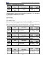
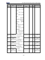
P4 Group--V/F Control
Function
Code
Name
Description
0: Linear curve
1: User-defined curve
2: 1.3 order
P4.00
V/F CURVE
torque_stepdown
3: 1.7 order
torque_stepdown
4: 2.0 order
torque_stepdown
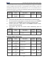
0: Linear curve. It is applicable for normal constant torque load.
1: User-defined curve. It can be defined through setting (P4.03~P4.08).
2~4: Torque_stepdown curve. It is applicable for variable torque load, such as blower,
pump and so on. Please refer to following figure.
Figure 6.11 Multiple V/F curve diagram.
Function
Code
P4.01
P4.02
Name
TORQUE
Description
0.0%: auto
BOOST
0.1%~10.0%
BOOST
0.0%~50.0%
CUT-OFF
(motor rated frequency)
48
Setting
Factory
Range
Setting
0.0~10.0
1.0%
0.0~50.0
20.0%
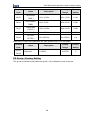
CHV160A series special inverter for water supply
Torque boost will take effect when output frequency is less than cut-off frequency of
torque boost (P4.02). Torque boost can improve the torque performance of V/F control at
low speed.
The value of torque boost should be determined by the load. The heavier the load, the
larger the value.
Notice: This value should not be too large, otherwise the motor would be over-heat
or the inverter would be tripped by over-current or over-load.
If P4.01 is set to 0, the inverter will boost the output torque according to the load
automatically. Please refer to following diagram.
Figure 6.12 Torque boost diagram.
Function
Code
Name
Description
Setting
Factory
Range
Setting
P4.03
V/F FREQ 1
0.00Hz~ P4.05
0.00~P4.05
5.00Hz
P4.04
V/F VOLTAGE 1
0.0%~100.0%
0.0~100.0
10.0%
P4.05
V/F FREQ 2
P4.03~ P4.07
P4.03~ P4.07
30.00Hz
P4.06
V/F VOLTAGE 2
0.0%~100.0%
0.0~100.0
60.0%
P4.07
V/F FREQ 3
P4.05~ P2.01
P4.05~ P2.01
50.00Hz
P4.08
V/F VOLTAGE 3
0.0%~100.0%
0.0~100.0
100.0%
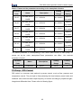
This function is only active when P4.00 is set to be 1. P4.03~P4.08 are used to set the
user-defined V/F curve. The value should be set according to the load characteristic of
motor.
Notice:
l
0<V1<V2<V3<rated voltage.
l
0<f1<f2<f3<rated frequency.
l
The voltage corresponding to low frequency should not be set too high,
otherwise it may cause motor overheat or inverter fault.
49
CHV160A series special inverter for water supply
Figure 6.13 V/F curve setting diagram.
Function
Name
Code
Description
Setting
Factory
Range
Setting
P4.09
V/F SLIPCOMP
0.00~10.00Hz
0.00~10.00
0.0Hz
The motor’s slip changes with the load torque, which results in the variance of motor
speed. The inverter’s output frequency can be adjusted automatically through slip
compensation according to the load torque. Therefore the change of speed due to the
load change can be reduced. The value of compensated slip is dependent on the motor’s
rated slip which can be calculated as below:
P 4.09 = fb − n * P / 60
n is motor rated speed (P2.02), and P is
Where motor rated frequency (P2.01) is,
pole pairs of motor.
Function
Code
Name
Description
Setting
Factory
Range
Setting
0~2
1
0: Disabled
P4.10
AVR
1: Enabled all the time
2: Disabled during
deceleration
AVR (Auto Voltage Regulation) function ensures the output voltage of inverter stable no
matter how the DC bus voltage changes. During deceleration, if AVR function is disabled,
the deceleration time will be short but the current will be big. If AVR function is enabled all
the time, the deceleration time will be long but the current will be small.
Function
Code
P4.11~
P4.15
Name
Reserved
Description
0~65535
50
Setting
Factory
Range
Setting
0~65535
0
CHV160A series special inverter for water supply
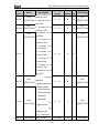
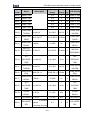
P5 Group--Input Terminals
The CHV160A series provides 8 multi-function digital input terminals and 2 analog inputs
terminals.
Function
Name
Code
P5.00
Description
NO/NC SELECT
0~0xFF
Setting
Factory
Range
Setting
0~0xFF
0
This code is to determine terminal status, normal-open or normal-colsed. When
corresponding bit is set to be 1, the terminal is normal-colsed input .This parameter is
hex-setting.ON-OFF signal corresponding bit is as follows:
BIT7
BIT6
BIT5
BIT4
BIT3
BIT2
BIT1
BIT0
S8
S7
S6
S5
S4
S3
S2
S1
Function
Code
P5.01
Name
INPUT
SELECTION
Description
0: Invalid
1: Valid
Setting
Factory
Range
Setting
0~1
0
0: ON-OFF signal is input through external input terminals.
1: ON-OFF signal is set through serial communication by host device.
Function
Code
Name
P5.02
S1 FUNCTION
P5.03
S2 FUNCTION
P5.04
S3 FUNCTION
P5.05
S4 FUNCTION
P5.06
S5 FUNCTION
P5.07
S6 FUNCTION
P5.08
S7 FUNCTION
Description
Programmable
multifunction terminal
Programmable
multifunction terminal
Programmable
multifunction terminal
Programmable
multifunction terminal
Programmable
multifunction terminal
Programmable
multifunction terminal
Programmable
multifunction terminal
51
Setting
Factory
Range
Setting
0~55
1
0~55
4
0~55
5
0~55
0
0~55
0
0~55
0
0~55
0
CHV160A series special inverter for water supply
Function
Code
P5.09
Name
S8 FUNCTION
Description
Setting
Factory
Range
Setting
0~55
0
Programmable
multifunction terminal
The meaning of each setting is shown in following table.
Setting
value
Function
0
Invalid
1
Forward
2
Reverse
Description
Please set unused terminals to be invalid to avoid
malfunction.
Please refer to description of P5.13.
Combine with FWD/REV operation to be 3-wire jog
control.
3
jog enable
4
Coast to stop
5
Reset fault
K1
K2
ON
OFF
OFF
ON
ON
OFF
OFF
ON
K3
OFF
ON
Command
Forward running
Reverse running
Forward jogging
Reverse jogging
The inverter blocks the output immediately. The motor
coasts to stop by its mechanical inertia.
Resets faults that have occurred. It has the same
function as STOP/RST.
When this terminal takes effect, inverter decelerates to
6
Running pause
stop and save current status, such as PLC, traverse
frequency and PID. When this terminal takes no effect,
inverter restores the status before pause.
7
External fault
Stop the inverter and output a alarm when a fault occurs
52
CHV160A series special inverter for water supply
Setting
value
Function
input
Description
in a peripheral device.
The reference frequency of inverter can be adjusted by
8
9
10
Up command
UP command and DOWN command.
DOWN
command
Clear
UP/DOWN
Use this terminal to clear UP/DOWN setting. Please
refer to description of P5.11.
11
12
13
14
15
16
17
18
Switch between
A and B
Switch between
P0.06
A and A+B
Switch between
ACC/DEC ramp
hold
B
11 valid
B
A
12 valid
A+B
A+B
A
13 valid
B and A+B
Pause PID
A
Terminal action
A+B
B
PID adjustment will be paused and inverter keeps output
frequency unchanged.
Pauses acceleration or deceleration and maintains
output frequency. When this terminal is disabled,
acceleration/deceleration is restarted.
Multi-step press 16 steps speed control can be realized by the
reference1
combination of these four terminals. For details, please
Multi-step press refer to following multi-step speed reference terminal
reference 2 status and according step value table.Such as:
Multi-step press 0000: select the multi-speed 0; 1111: multi-speed 15.
Notice: multi-speed 1 is low bit, and multi-speed 4 is
reference 3
high bit.
19
Multi-step press
Multi-speed
Multi-speed
Multi-speed
Multi-speed
reference 4
terminal 4
terminal 3
terminal 2
terminal 1
BIT3
BIT2
BIT1
BIT0
53
CHV160A series special inverter for water supply
Setting
value
20
Function
Manual soft
start debugging
Description
Manual soft start of each motor must be corresponding
to soft start terminal ,and the status should
be
1.( short-connecting with COM)
Manual
21
round-robin
command
These parameters are to set the variable frequency
pumps which need to be soft started. Please used
together with the enabled terminal.
When the enabled terminal, command of soft start and
22~28
Manual soft
the running command of inverter are all valid, the motor
start of motor
will be soft started by inverter. And when the frequency
A~G
reachs to P8.13 (the switching frequency), the motor will
switch to be the grid-frequency status.
If several commands of soft start are valid at the same
time, the inverter will soft start and switch motors
according to the closed sequency of each terminal.
29~35
36
37
38
Motor A~G
disabled
up W LEV ltd
Inlet reservoir
low W LEV ltd
Please refer to P8.27.
Inlet reser W
LEV on W short
reservoir up W
LEV ltd
40
switch logic. It’s for repair.
Inlet reservoir
Sewage
39
When the command is valid, relevant motor will be out of
Sewage reser
low W level ltd
The signal is a kind of ON-OFF..When the sewage level
is higher than upper limit, sewage pump will be switched
to run; If it is lower than lower limit, the sewage pump will
stop running.
When it is valid, PID0 (Defined by P3) will be switched to
41
PID switch
PID1
(Defined
by
PD),
and
the
parameters of PID wll also be switched.
54
corresponding
CHV160A series special inverter for water supply
Setting
value
42~50
Function
Code
P5.10
Function
Description
Reserved
Name
Description
Sx FILTER TIMES 0~10
Setting
Factory
Range
Setting
0~10
5
This parameter is used to set filter strength of terminals (S1~S8). When interference is
heavy, user should increase this value to prevent malfunction.
Function
Code
P5.11
Name
UP/DOWN RATE
Description
0.01~50.00Hz/s
Setting
Factory
Range
Setting
0.01~50.00
0.50Hz/s
This parameter is used to determine how fast UP/DOWN setting changes.
Function
Code
P5.12
P5.13
P5.14
P5.15
P5.16
P5.17
P5.18
Name
AI1 LOW LIMIT
AI1 LOW
SETTING
AI1 UP LIMIT
AI1 UP
SETTING
AI1 FILTER
TIME
AI2 LOW LIMIT
Setting
Factory
Range
Setting
0.00~10.00
0.00V
-100.0~100.0
0.0%
0.00~10.00
10.00V
-100.0~100.0
100.0%
0.00s~10.00s
0.00~10.00
0.10s
0.00V~10.00V
0.00~10.00
0.00V
-100.0~100.0
0.0%
Description
0.00V~10.00V
-100.0%~100.0%
0.00V~10.00V
-100.0%~100.0%
AI2 LOW SETTING -100.0%~100.0%
P5.19
AI2 UP LIMIT
P5.20
AI2 UP SETTING
0.00V~10.00V
-100.0%~100.0%
P5.21
AI2 FILTER TIME
0.00s~10.00s
0.00~10.00
10.00V
-100.0~100.0
100.0%
0.00~10.00
0.10s
These parameters determine the relationship between analog input voltage and the
corresponding setting value. When the analog input voltage exceeds the range between
lower limit and upper limit, it will be regarded as the upper limit or lower limit.
The analog input AI1 can only provide voltage input, and the range is 0V~10V.
For different applications, the corresponding value of 100.0% analog setting is different.
For details, please refer to description of each application.
Notice: AI1 lower limit must be less or equal to AI1 upper limit.
55
CHV160A series special inverter for water supply
Figure 6.14 Relationship between AI and corresponding setting.
Function
Code
P5.22~
P5.25
Name
Reserved
Description
0~65535
Setting
Factory
Range
Setting
0~65535
0.00V
P6 Group -- Output Terminals
CHV160A series standrad model supplies 3 multifunctional relay output terminals,2
multifunctional analog output terminals. The extension card supplies 8 pump intelligent
switched relay output terminals.
Function
Code
P6.00
P6.01
P6.02
Setting
Value
Name
RO1
SELECTION
RO2
SELECTION
RO3
SELECTION
Setting
Factory
Range
Setting
Relay output
0~30
3
Relay output
0~30
21
Relay output
0~30
22
Description
Function
Description
0
No output
1
Run forward
Output terminal has no function.
ON: During forward run.
2
Run reverse
ON: During reverse run.
3
Fault output
ON: Inverter is in fault status.
4
Motor overload
Please refer to description of PA.04~PA.06.
56
CHV160A series special inverter for water supply
Setting
Value
5
Function
Description
Inverter overload
Please refer to description of PA.04~PA.06.
6
FDT reached
Please refer to description of PC.10, PC.11.
7
Frequency reached
Please refer to description of PC.12.
8
Zero speed running
ON: The running frequency of inverter is zero.
9
10
11
Running time
reached
Upper frequency
limit reached
Lower frequency
limit reached
12
Run ready
13
Motor running
14
Stop pulse output
Please refer to description of PC.09.
ON: Running frequency reaches the value of P0.07.
ON: Running frequency reaches the value of P0.08.
ON: Inverter is ready (no fault, power is ON).
ON: Inverter has output signal.
Output pulse signal for 2s when running frequency is
lower than 0.1Hz.
Output “ON” when the feedback pressure is equal to
15
Over press alarm
or greater than PA.14(Over-pressure protection
value ) and it lasts the delay time set by PA.15.
Output “ON” when the feedback pressure is equal to
16
Under press alarm
or
less
than
PA.16(Under-pressure
protection
value), and it lasts the delay time set by PA.17.
Dormant
17
Operation
Output “ON” when the dormancy running status
indication
18
19
20
Backup pressure
operat indica
Reservoir water
short indicat
Faulty pump
indication
The terminal will output “ ON” when the system is
running with reserved pressure . Please refer to
P8.32.
Output ON when water level of pool is lower than the
shortage level.
Output ON once there is any pump at fault.
In water-supply mode, output “ON” means that .H
21
H pump control
pump has been switched on.H pump is only suitable
for grid frequency control.
57
CHV160A series special inverter for water supply
Setting
Function
Value
Description
In water-supply mode, output “ON” means that .I
22
I pump control
pump has been switched on.I pump is only suitable
for grid frequency control.
23~30
Reserved
Function
Reserved
Name
Code
Description
Setting
Factory
Range
Setting
P6.03
RT1 SELECTION 0~14
0~14
0
P6.04
RT2 SELECTION 0~14
0~14
0
P6.05
RT3 SELECTION 0~14
0~14
0
P6.06
RT4 SELECTION 0~14
0~14
0
P6.07
RT5 SELECTION 0~14
0~14
0
P6.08
RT6 SELECTION 0~14
0~14
0
P6.09
RT7 SELECTION 0~14
0~14
0
P6.10
RT8 SELECTION 0~14
0~14
0
These parameters are to set the output function of relay on water-supply card,the
detailsis as follows:
Setting value
Function
Description
0
No function
1
Connect A for var freq CON
2
Connect A for pow freq CON
3
Connect B for var freq CON
4
Connect B for pow freq CON
5
Connect C for var freq CON
6
Connect C for pow freq CON
7
Connect D for var freq CON
8
Connect D for pow freq CON
9
Connect E for var freq CON
10
Connect E for pow freq CON
11
Connect F for var freq CON
12
Connect F for pow freq CON
Terminal is invalid.
13
Connect G for var freq CON
14
Connect G for pow freq CON
58
Variable frequency pump needs
two control signals: frequency
control and grid frequency
control,but grid frequency
pump ,sewage pump,anddormancy
pump need only one control
signal :grid frequency control.
CHV160A series special inverter for water supply
Function
Name
Code
P6.11
P6.12
Description
AO1
Multifunctional
SELECTION
AO2
Multifunctional
SELECTION
analog
output
analog
output
Setting
Factory
Range
Setting
0~14
0
0~14
0
AO/HDO output functions are indicated in the following table:
Setting Value
Function
0
Running frequency
0~maximum frequency (P0.06)
Range
1
Setting frequency
0~ maximum frequency (P0.06)
2
Motor speed
0~2* rated synchronous speed of motor
3
Output current
0~2* inverter rated current
4
Output voltage
0~2* inverter rated voltage
5
Reserved
6
Reserved
7
AI1 voltage/current
0~10V/0~20mA
8
AI2 voltage/current
0~10V/0~20mA
9~15
Reserved
Function
Code
P6.13
P6.14
P6.15
P6.16
P6.17
P6.18
P6.19
P6.20
Name
AO1 LOW LIMIT
AO1 LOW
OUTPUT
AO1 UP LIMIT
AO1 UP
OUTPUT
AO2 LOW LIMIT
AO2 LOW
OUTPUT
AO2 UP LIMIT
AO2 UP
OUTPUT
Setting
Factory
Range
Setting
0.0%~100.0%
0.0~100.0
0.0%
0.00V ~10.00V
0.00~10.00
0.00V
0.0%~100.0%
0.0~100.0
100.0%
0.00V ~10.00V
0.00~10.00
10.00V
0.0%~100.0%
0.0~100.0
0.0%
0.00V ~10.00V
0.00~10.00
0.00V
0.0%~100.0%
0.0~100.0
100.0%
0.00V ~10.00V
0.00~10.00
10.00V
Description
59
CHV160A series special inverter for water supply
These parameters determine the relationship between analog output voltage/current and
the corresponding output value. When the analog output value exceeds the range
between lower limit and upper limit, it will output the upper limit or lower limit.
When AO is current output, 1mA is corresponding to 0.5V.
For different applications, the corresponding value of 100.0% analog output is different.
For details, please refer to description of each application.
Figure 6.15 Relationship between AO and corresponding setting.
Function
Code
P6.21~
P6.24
Name
Reserved
Description
0~65535
Setting
Factory
Range
Setting
0~65535
0.0%
Setting
Factory
Range
Setting
0~65535
0
P7 Group--Display Interface
Function
Code
P7.00
Name
USER
PASSWORD
Description
0~65535
The password protection function will be valid when set to be any nonzero data. When
P7.00 is set to be 00000, user’s password set before will be cleared and the password
protection function will be disabled.
After the password has been set and becomes valid, the user can not access menu if the
user’s password is not correct. Only when a correct user’s password is input, the user can
see and modify the parameters. Please keep user’s password in mind.
Function
Code
P7.01
Name
Description
LANGUAGE
0: Chinese
SELECT
1: English
60
Setting
Factory
Range
Setting
0~1
0
CHV160A series special inverter for water supply
Function
Code
Name
Description
Setting
Factory
Range
Setting
0~2
0
0: Invalid
P7.02
PARA COPY
1: Upload
2: Download
P7.02 will take effect when LCD keypad is used.
1: All value of parameters will be uploaded from inverter to LCD.
2: All value of parameters will be downloaded from LCD to inverter.
Notice:
When upload or download operation completes, P7.02 will be set to 0
automatically.
Function
Code
Name
Description
Setting
Factory
Range
Setting
0~3
0
0: Quick debugging mode
P7.03
QUICK/JOG
FUNC
1: FDW/REV switch
2: Jog
3: Clear UP/DOWN setting
QUICK/JOG is a multifunctional key, whose function can be defined by P7.03.
0: Quick debugging mode: Please refer to description of Chapter 5.
1: FWD/REV switching: Press QUICK/JOG, the running direction of inverter will reverse.
It is only valid if P0.01 is set to be 0.
2: Jog: Press QUICK/JOG, the inverter will jog.
3: Clear UP/DOWN setting: Press QUICK/JOG, the UP/DOWN setting will be cleared.
Function
Code
Name
Description
Setting
Factory
Range
Setting
0~3
0
0: Valid when keypad
control (P0.01=0)
1: Valid when keypad or
P7.04
STOP/RST
FUNC
terminal control
(P0.01=0 or 1)
2: Valid when keypad or
COM control (P0.01=0
or 2)
3: Always valid
Notice:
l
The value of P7.04 only determines the STOP function of STOP/RST.
61
CHV160A series special inverter for water supply
l
The RESET function of STOP/RST is always valid.
Function
Name
Code
Description
Setting
Factory
Range
Setting
0~3
0
0: Preferential to
external keypad
1: Both display&external
P7.05
KEYPAD
valid.
DISPLAY
2: Both display& local
key valid.
3: Both display & Both
valid.
0: When external keypad exists, local keypad will be invalid.
1: Local and external keypad display simultaneously, only the key of external keypad is
valid.
2: Local and external keypad display simultaneously, only the key of local keypad is valid.
3: Local and external keypad display simultaneously, both keys of local and external
keypad are valid.
Notice:
l
This function should be used cautiously, otherwise it may cause malfunction.
l
When P7.05 is set to be 1, local keypad is valid if external keypad is not
connected.
l
When LCD keypad is connected, P7.05 must be set to be 0.
Function
Name
Code
P7.06
RUNNING
DISPLAY
Description
0~0xFFFF
Setting
Factory
Range
Setting
0~0xFFFF
0x01F9
P7.06 defines the parameters that can be displayed by LED in running status. If Bit is 0,
the parameter will not be displayed; If Bit is 1, the parameter will be displayed. Press
》 /SHIFT to scroll through these parameters in right order. Press DATA/ENT +
QUICK/JOG to scroll through these parameters in left order.
The display content corresponding to each bit of P7.06 is described in the following table:
BIT7
BIT6
BIT5
Output
Input
AI1
terminal
terminal
status
status
BIT4
BIT3
PID
feedback
BIT2
BIT1
PID preset Reserved Reserved
62
BIT0
Rotation
speed
CHV160A series special inverter for water supply
BIT15
BIT14
BIT13
ReservedReserved
BIT12
BIT11
BIT10
BIT9
BIT8
Reserved Reserved Reserved Reserved Reserved
AI2
For example, if user wants to display rotation speed, output power, output torque, PID
preset and AI1, the value of each bit is as the following table:
BIT7
BIT6
BIT5
BIT4
BIT3
BIT2
BIT1
BIT0
1
0
0
0
1
1
1
1
BIT14
BIT13
BIT12
BIT11
BIT10
BIT9
BIT8
0
0
0
0
0
0
BIT15
0
0
The value of P7.06 is 008Fh.
Notice: I/O terminal status is displayed in decimal. For details, please refer to
description of P7.19 and P7.20.
Function
Name
Code
P7.07
STOP DISPLAY
Setting
Factory
Range
Setting
1~0xFFFF
0xFF
Description
1~0xFFFF
P7.07 determines the display parameters in stop status. The setting method is similar
with P7.06.
The display content corresponding to each bit of P7.07 is described in the following table:
BIT7
BIT6
AI2
AI1
BIT15
BIT14
BIT5
BIT4
BIT3
PID
PID
feedback
preset
BIT13
BIT12
BIT2
Output
Input
terminal
terminal
status
status
BIT11
BIT10
BIT1
BIT0
DC bus
Reference
voltage
frequency
BIT9
BIT8
Reserved Reserved Reserved Reserved Reserved Reserved Reserved Reserved
Function
Code
P7.08
Name
RECTIFIER
TEMP
P7.09
IGBT TEMP
P7.10
MCU VERSION
P7.11
DSP VERSION
P7.12
TOTAL RUN
TIME
Description
Setting
Factory
Range
Setting
0~100.0℃
0~100.0℃
0~65535h
Rectifier module temperature: Indicates the temperature of rectifier module. Overheat
63
CHV160A series special inverter for water supply
protection point of different inverter may be different.
IGBT module temperature: Indicates the temperature of IGBT module. Overheat
protection point of different inverter may be different.
MCU Software version: Indicates current software version of MCU.
DSP Software version: Indicates current software version of DSP
Accumulated running time: Displays accumulated running time of inverter.
Notice: Above parameters are read only.
Function
Name
Code
P7.13
P7.14
P7.15
Description
3rd LATEST
FAULT
2nd LATEST
FAULT
CURRENT
FAULT
Setting
Factory
Range
Setting
0~30
0~30
0~30
0~30
0~30
0~30
These parameters record three recent fault types. For details, please refer to description
of chapter 7.
Function
Code
P7.16
P7.17
P7.18
Name
FAULT
PREQ
FAULT
CURR
FAULT
DC VOLT
Setting Factory
Description
Range Setting
Output frequency at current fault.
Output current at current fault.
DC bus voltage at current fault.
This value records ON-OFF input terminal
status at current fault. The meaning of each
bit is as below:
FAULT
P7.19
Sx
STATUS
BIT7 BIT6 BIT5 BIT4 BIT3 BIT2 BIT1 BIT0
S8
S7
S6
S5
S4
S3
S2
S1
1 indicates corresponding input terminal is
ON, while 0 indicates OFF.
Notice: This value is displayed as
decimal.
64
CHV160A series special inverter for water supply
Function
Name
Code
Setting Factory
Description
Range Setting
This value records output terminal status at
current fault. The meaning of each bit is as
below:
BIT10 BIT9
BIT8
BIT7
BIT6
RT8
RT7
RT6
RT5
RT4
BIT5
BIT4
BIT3
BIT2
BIT1
BIT0
RT3
RT2
RT1
RO3
RO2
RO1
FAULT
P7.20
DO
STATUS
1 indicates corresponding output terminal is
ON, while 0 indicates OFF.
Notice: This value is displayed as
decimal.
Function
Code
P7.21
Name
ERR-PUMP
NOTE
Description
0~0x1FF
Setting
Factory
Range
Setting
0~0x1FF
In constant pressure water-supply mode, if any pump is at fault, the corresponding bit will
be 1.When P8.33 is 1,the corresponding type of faulty pump will be invalid,and the faulty
pump will stop running,and stop switching
BIT9
BIT8
BIT7
BIT6
BIT5
Reserved
Reserved
Reserved
G pump
F pump
BIT4
BIT3
BIT2
BIT1
BIT0
E pump
D pump
C pump
B pump
A pump
For example: When P7.21=23H=00100011b, it means that pump A, pump B and pump F
are at fault.
Function
Code
P7.22~
P7.24
Name
Description
Reserved
0~65535
65
Setting
Factory
Range
Setting
0~65535
0
CHV160A series special inverter for water supply
P8 Group--Water-supply Function
Function
Name
Code
P8.00
Description
WATER
Setting
Factory
Range
Setting
0~1
1
0~1
SUPPLY SEL
0:Disabled
The water-supply logic is invalid.Inverter is in general control mode.
1: Enabled
It is suitable for constant pressure water-supply system.For example: life and production
constant pressure water-supply system, municipal water-supply system and sewage
processing
system.
In
other
familiar
systems,such
as
constant
pressure
oil-supply,constant pressure HVAC, it is available too.
Notice: when P8.00 is set to be 1, PID is the default as frequency given.and other
frequency sources determined by P0.02-P0.05 are invalid.
Function
Name
Code
P8.01
CONVERT-PUMP
SEL
Description
0~1
Setting
Factory
Range
Setting
0~1
0
0: Fixed FRQ conversion-pump
Fix one pump as a variable-frequency pump which is drived directly by inverter, and
others are grid-frequency pump which are controlled by programmable relay.
So, CHV160A can drive 1 variable-frequency pump and 9 grid-frequency pumps at most.
1: Circular FRQ conversion-pump
Only one pump can be used as an variable frequency pump, and others are as
grid-frequency pumps at the same time, the variable frequency pumps can be in turn.
So CHV160A can dirve 4 avariable-frequency pumps and 2 grid-frequency pumps at
most.
Function
Code
P8.02
Name
H,I SEL
Description
0~3
0: Disabled
1: H pump enabled
2: I pump enabled
3: H, I both enabled.
66
Setting
Factory
Range
Setting
0~3
3
CHV160A series special inverter for water supply
Function
Code
Name
Description
Setting
Factory
Range
Setting
PUMP A SEL
0~4
0~4
0
P8.04
PUMP B SEL
0~4
0~4
0
P8.05
PUMP C SEL
0~4
0~4
0
P8.06
PUMP D SEL
0~4
0~4
0
P8.07
PUMP E SEL
0~4
0~4
0
P8.08
PUMP F SEL
0~4
0~4
0
P8.09
PUMP G SEL
0~4
0~4
0
P8.03
0: Pump invalid.
The corresponding pump is not installed or does not work.
1: Variable frequency CON pump
The corresponding pump is started by inverter.When it can not be switched,the pump can
adjust the output automatically
as variable adjust pump to make sure that the pressure
to be constant.
When fulfilling the switching requirement, the pump will switch to run at grid-frequency or
stop running.
NOICE: When P8.01=0, and A-G pumps are set as variable frequency pumps,the
corresponding pump will be invalid.
2: Power frequency pump
The pump only run at grid-frequency, when the capacity of power network is big enough
and the power of pump is less than 15kW, the pumps will be started with total voltage
directly.If the power of pump is greater than 18.kW, it is suggested to start with buck
start-up mode, such as Star-Delta step-down start, Auto coupling step-down start and soft
start, so as to reduce impact on pipe network and power network system.
3: Dedicated dormant pump
When dormancy conditions are fulfilled, the system will be on the dormancy running
status, and start the dormancy grid-frequency pump to maintain the pressure of pipe
network.The dormancy pump won’t be running until the system exits dormancy status.
4: Dedicated dredge pump
It is a grid-frequency pump, when waterlevel of Sewage-pool control function is enabled,
and water level sensors are installed correctly, system will start and stop of sewage pump
according to the detected water-level signals (which are).
67
CHV160A series special inverter for water supply
Function
Name
Code
PUMP ADD
P8.10
P8.11
TOLERA
PUMP ADD
P8.13
DELAY
SWITCH
FREQUENCY
Factory
Range
Setting
0.0~30.0
10.0%
P8.16~P0.07
50.00Hz
0~3600
5s
0.0~P0.07
50.00Hz
0.0~30.0%
PUMP ADD FREQ P8.16~P0.07
P8.12
Setting
Description
0~3600s
0.0~P0.07
The four parameters set the conditions of adding pump.
1: When frequency of variable-frequency pump reach the frequency of P8.11,at the same
time, ,pressure feedback value<pressure set value-pressure tolerance,and it lasts for
delay time (determined by P8.12),then the system adds pump.
2: 100% of pressure tolerance is corresponding with P3.02 (Maximum of PID).
3: P8.11 is a threshold frequency to add pump.When the pressure conditions are not
satisfied, pump-added logic isstarted, which is as follow:
Add variable-frequency pump: Switch current variable-frequency pump to be a
grid-frequency pump and start a new variable–frequency pump.
Add grid-frequency pump: Start the pumps using programmable relay ,at the same time,
the current variable-frequency pump decelerate to the frequency of minusing pump
according to the setted deceleration time determinded by P8.14, and then go on running
with PID control.
It can stabilize fluctuate of system pressure and decreace pressure jump when add
pump.
4: P8.13 switching frequency of variable-frequency pumps.
In the switch process, there is delay time from disconnecting variable-frequency contactor
to closeing grid-frequency contactor, so variable-frequency pump will accelerate to a
higher frequency (which is the switch frequency) before switching in order to make up the
depreciation of pipe network pressure in the delay time.
The switch process is as follow: Variable-frequency pump accelerates to the switch
frequency, stops output and disconnects the contactor,finally closes grid-frequency
contactor.
68
CHV160A series special inverter for water supply
Function
Code
P8.14
Name
VFP DECELER
TIME
Description
0.0~100.0%
Setting
Factory
Range
Setting
0.0~100.0
10.0s
The conditions of adding pump are satisfied,if the added pump is grid-frequency
pump,the variable-frequency pump should decelerate to the frequency of minusing pump
according with the setting deceleration time,and goes on carring out with PID control.In
the process,the deceleration time is set by P8.14.
Function
Code
P8.15
P8.16
P8.17
Name
PUMP REDU
TOLERA
Description
0.0~30.0%
PUMP REDU FRQ P8.08~P8.11
PUMP REDU
DELAY
0~3600s
Setting
Factory
Range
Setting
0.0~30.0
10.0%
P8.08~P8.11
5.00Hz
0~3600
5s
The three parameters set the conditions of reducing pump.
1: When frequency of variable-frequency pump reach the frequency (determined by
P8.16), at the same time, feedback pressure >setting pressure+pressure toleranceand it
lasts for delay time (determined by P8.17), then system starts to reduce pump.
2: 100% of the pressure tolerance is corresponding to P3.02 (Maximum of PID).
3: Running frequency of pump reduced
When there are some grid-frequency pumps running, what is more variable-frequency
pump decelerate to the frequency of pump reduced, and it last for delay time (determined
by P8.17), when these conditions are satisfied, it starts to reduce pump.
Reduce grid-frequency pump: Resect the pump with programmable relay, and the current
variable-frequency pump accelerate to the frequency of pump reduced according to the
setted acceleration (determined by P8.18), and go on running with PID control.
It can stabilize fluctuate of system pressure when reduces pumps.
Function
Code
P8.18
Name
VFP ACCELER
TIME
Description
0.0~100.0%
Setting
Factory
Range
Setting
0.0~100.0
10.0s
When the conditions of reducing pump are satisfied, the system will cut grid-frequency
pump off. The variable frequency pump should accelerate to the frequency of pump
added according to the acceleration time, and then go on running with PID control. In the
69
CHV160A series special inverter for water supply
process, the acceleration time of variable frequency pump determined by this code.
Function
Code
Name
Description
Setting
Factory
Range
Setting
P8.19
CLOSE DELAY
0.1~9.9%
0.1~9.9
0.5s
P8.20
TRIP DELAY
0.1~9.9%
0.1~9.9
0.5s
It’s considered that there are mechanical delay time when contactor closes or opens,even
more there are remanence when vairale frequency pump switch to run at grid frequency
which may make the action failure. The parameters above are used to solve these
problems.
1: Before inverter enables the next available frequency pump,it will send contactor closing
command, there are time difference between command has been sent and the inverter
starts to output by reason of mechanical delay,that’s contactor closing time.
2: The contactor opening time is time defferece from the inverter outputs coast to stop
command to inverter outputs grid-frequency contactor closing command.it normally used
for which the power of pump is greater than 45kW and the variable-frequency pump
needs to be switched to run at grid frequency,It can minish switching current and improve
the success percentage of switching.
Function
Code
Name
Description
Setting
Factory
Range
Setting
0~1
0
P8.10~60.0
10.0%
0~3600
5s
0: Dormancy enabled
P8.21
PID SLEEP SEL
1: Running at lower limit
FRQ
P8.22
P8.23
AWOKE
TOLERA
AWOKE DELAY
P8.10~60.0%
0~3600s
When dormancy function is available, One-and-only-one available frequency pump is
running, and the status is eligible for pump reduced condition (include the delay time of
pump reduced), the available frequency pump start to sleep and stand by,the system
enters dormancy state. If there is sleep lower power pump, it will start to run automatically
and keep running till system exists dormancy state.
In the dormancy state, pressure feedback < setting pressure-pressure tolerance of
dormancy awaked, and it lasts for the delay time (determined by P8.23), the dormancy
state quits, and dormancy pump stops, variable frequency pump starts.
Notice: 100% of the P8.22 is corresponding with P3.02 (Maximum of PID).
70
CHV160A series special inverter for water supply
Function
Code
P8.24
Name
Setting
Factory
Range
Setting
0.0~6553.5
0.0h
Description
PFP ROU-ROB
0.0~6553.5
PER
The parameter set the timing circulation period of grid-frequency pump.
0: Invalid.
Pumps switching logic is First-In-First-Out.
Not 0: Valid.
The setting value is circulation period.It is sugguested that the function should be
selected when capacitys of each grid-frequency pump are almost the same( except
sewage pump and dormancy pump).
If there are two or more grid-frequency pumps,so all pumps( except sewage pump and
dormancy pump ) will join the rotation,no rotation if there is only one grid-frequency pump.
Function
Code
P8.25
Name
VFP ROU-ROB
PER
Setting
Factory
Range
Setting
0.0~6553.5
0.0h
Description
0.0~6553.5
The setting is similar with P8.24; please refer it for the details.
Function
Code
P8.26
Name
SW FREQ
MANUAL
Description
0~P0.07
Setting
Factory
Range
Setting
0~P0.07
50.00Hz
When use manual soft start, the parameter sets the running frequency of inverter before
switching to grid-frequency pump.
Function
Code
P8.27
Name
W lEVEL SI
INPUT
Description
0~2
Setting
Factory
Range
Setting
0~2
0
The parameter is set to whether control level of inlet pool or not.
0: No input.
1: Input by digital input termi
The level control signal is switch value.
2: Input by analog input terminal
Level signal input channel is selected by P8.28, and level limit is confirmed by
P8.29~P8.31.
71
CHV160A series special inverter for water supply
Level control mode:
1: When pool level changes from high to low, and the level is higher than lower limit level,
system runs with normal setting pressure mode.When the level is lower than lower limit
level and higher than water shortage level, system runs with abnormal spare pressure
mode (determined by P8.32); when the level is lower than water shortage level, system
stop running.
2. When pool level changes from low level to high level, system do not run when the level
is lower than the lower limit level, when the level is higher than lower limit level and lower
than the upper limit level, system run with spare pressure mode(determined by P8.32);
When the level is higher than upper limit level, system returns to run with normal
pressure.
Figure 6.16 Level change and pressure given
Function
Code
P8.28
Name
WL SI ANAL
INPUT
Description
Setting
Factory
Range
Setting
0~2
0
0:AI1 input
1:AI2 input
2:Modbus input
P8.29
UP W lEVEL LTD
P8.30
Low W lEVEL LTD 0.0~P8.29
0.0~100.0%
0.0~100.0
60.0%
0.0~P8.29
40.0%
0.0~P8.30
20.0%
SHORTAGE W
P8.31
LEVELshortage
0.0~P8.30
level
The pressure percentage is relative to 100% of pool feedback pressure.
72
CHV160A series special inverter for water supply
Function
Code
P8.32
Name
BACKUP
PRESSURE
Description
0~100.0%
Setting
Factory
Range
Setting
0~100.0
0.0%
Known by the aforementioned, when the pool level is lower than the lower limit level,
spare pressure is needed so as to avoid that the level draw too fast and even that pump
run without load.
100% of the P8.22 is corresponding with P3.02 (Maximum of PID).
Function
Code
P8.33
Name
Description
FAULT
HANDLING
Setting
Factory
Range
Setting
0-1
0
The function code defines the actions in event of the failure.
0: Breakdown of the entire system.
1: To next VFP. No VFP, then PFP.
Current variable frequency pump (which is) at fault is resected automaticly, and switched
to next variable-frequency pump.
If there is only one variable-frequency pump, system stops running.
2: Reserved.
Notice: If the fault automatic reset function is enable, after system resets for times
set, if the fault is not cleared out, the system will deal with it according to the mode
set by this function code.
Function
Code
P8.34~
P8.39
Name
Reserved
Description
0~65535
Setting
Factory
Range
Setting
0~65535
0
P9 Group--Timing Watering and Multi-given Function Group
Function
Code
P9.00
Name
CURRENT
MOMENT
Description
0.00~23.59
Setting
Factory
Range
Setting
0.00~23.59
Set and display current time, users can modify the parameter to set the time,the meaning
is as follows:
73
CHV160A series special inverter for water supply
Figure 6.17 meaning of time display
The time is the base standard for setting multi-pressure time, the parameter will update as
real-time.
Notice: The system will run constantly when the inveter is power-off, if the clock is
stop, please check the battery of control board.
Function
Code
P9.01
Name
PRESSURE
STEPS
Description
1~8
Setting
Factory
Range
Setting
1~8
1
The parameter set the segment numbers of pressure, only T1 is the default, namely one
pressure segment is effective all day.When several segments are selected, it means
multi-segment pressure is effective, and the setting is repeated everyday.
The parameter is for setting the pressure segment and corresponding pressure.
1. Principle of setting time: T1≤T2≤T3≤T4≤T5≤T6≤T7≤T8
2. Segment T1 is the time from threshold T1 to threshold T2, segment T2 is the time from
threshold T2 to threshold T3, and so forth, segment T8 is the time from threshold T8 to
threshold T1.
3. If threshold of one segment is same as ultimate of previous segment, the segment is
invalid, and they are merged as one segment.
4. If the segments are equal, only one segment is effective
Function
Code
Name
Description
everyday.
Setting
Factory
Range
Setting
P9.18
MULTI SET 0
0.0~100.0%
0.0~100.0
0.0%
P9.19
MULTI SET 1
0.0~100.0%
0.0~100.0
0.0%
P9.20
MULTI SET 2
0.0~100.0%
0.0~100.0
0.0%
P9.21
MULTI SET 3
0.0~100.0%
0.0~100.0
0.0%
P9.22
MULTI SET 4
0.0~100.0%
0.0~100.0
0.0%
P9.23
MULTI SET 5
0.0~100.0%
0.0~100.0
0.0%
P9.24
MULTI SET 6
0.0~100.0%
0.0~100.0
0.0%
P9.25
MULTI SET 7
0.0~100.0%
0.0~100.0
0.0%
P9.26
MULTI SET 8
0.0~100.0%
0.0~100.0
0.0%
74
CHV160A series special inverter for water supply
Function
Code
Name
Description
Setting
Factory
Range
Setting
P9.27
MULTI SET 9
0.0~100.0%
0.0~100.0
0.0%
P9.28
MULTI SET 10
0.0~100.0%
0.0~100.0
0.0%
P9.29
MULTI SET 11
0.0~100.0%
0.0~100.0
0.0%
P9.30
MULTI SET 12
0.0~100.0%
0.0~100.0
0.0%
P9.31
MULTI SET 13
0.0~100.0%
0.0~100.0
0.0%
P9.32
MULTI SET 14
0.0~100.0%
0.0~100.0
0.0%
P9.33
MULTI SET 15
0.0~100.0%
0.0~100.0
0.0%
100.0% of pressure given is corresponding to maximum of PID,when P3.06 is set to be
5,the pressure segment is defined by the combination of multi-segment pressure
terminals,the corresponding relation between multi-segment pressure and terminals(S1、
S2、S3、 S4) is as follow:
S1
OFF
ON
OFF
ON
OFF
ON
OFF
ON
S2
OFF
OFF
ON
ON
OFF
OFF
ON
ON
S3
OFF
OFF
OFF
OFF
ON
ON
ON
ON
S4
OFF
OFF
OFF
OFF
OFF
OFF
OFF
OFF
Segment
0
1
2
3
4
5
6
7
S1
OFF
ON
OFF
ON
OFF
ON
OFF
ON
S2
OFF
OFF
ON
ON
OFF
OFF
ON
ON
S3
OFF
OFF
OFF
OFF
ON
ON
ON
ON
S4
ON
ON
ON
ON
ON
ON
ON
ON
Segment
8
9
10
11
12
13
14
15
Function
Code
P9.34~
P9.37
Name
Reserved
Description
0~65535
Setting
Factory
Range
Setting
0~65535
0
Setting
Factory
Range
Setting
0~1
1
PA Group--Protection Parameters
Function
Code
PA.00
Name
IN PHASE FALL
Description
0: Disabled
1: Enabled
75
CHV160A series special inverter for water supply
Function
Code
PA.01
Name
Description
OUT PHASE
0: Disabled
FALL
1: Enabled
Setting
Factory
Range
Setting
0~1
1
Notice: Please be cautious to set these parameters as disabled. Otherwise it may
cause inverter and motor overheat even damaged.
Function
Code
PA.02
Name
MOTOR
OVERLOAD
Description
Setting
Factory
Range
Setting
0~2
2
0: Disabled
1: Normal motor
2: Variable frequency motor
1: For normal motor, the lower the speed, the poorer the cooling effect. Based on this
reason, if output frequency is lower than 30Hz, inverter will reduce the motor overload
protection threshold to prevent normal motor from overheat.
2: As the cooling effect of variable frequency motor has nothing to do with running speed,
it is not required to adjust the motor overload protection threshold.
Function
Code
PA.03
Name
OVERLOAD
CURR
Description
20.0%~120.0%
Setting
Factory
Range
Setting
20.0~120.0
100.0%
Figure 6.18 Motor overload protection curve.
The value can be determined by the following formula:
Motor overload protection current = (motor rated current / inverter rated current) * 100%.
Notice:
l
This parameter is normally used when rated power of inverter is greater than
rated power of motor.
76
CHV160A series special inverter for water supply
l
Motor overload protection time: 60s with 200% of rated current. For details,
please refer to above figure.
Function
Name
Code
PA.04
OL WARN
CURR
Description
20.0%~150.0%
Setting
Factory
Range
Setting
20.0~150.0
110.0%
0~3
0
0.0~30.0
5.0s
0: Always based on I motor
PA.05
OL WARN
1: Detect based on I motor
SELECT
2: Always based on I INVE
3: Detect based on I INVE
PA.06
OL WARN
DELAY
0.0~30.0s
The value of PA.05 determines the pre-warning category, such as motor overload (OL1)
or inverter overload (OL2).
PA.04 determines the current threshold of pre-warning actionn, it is a percentage of the
rated current. When output current of inverter exceeds the value of PA.04 and last the
duration determined by PA.06, inverter will output a pre-warning signal. Please refer to
following diagram:
Figure 6.19 Overload pre-warning schematic diagram.
Function
Code
PA.07
Name
TRIPFREE
POINT
Description
230.0V~600.0V
77
Setting
Factory
Range
Setting
230.0~600.0
450.0V
CHV160A series special inverter for water supply
Function
Code
PA.08
Name
TRIPFREE
DECRATE
Description
0.00Hz~P0.07
Setting
Factory
Range
Setting
0.00~P0.07
0.00Hz
If Pb.08 is set to be 0, the trip-free function is invalid.
Trip-free function enables the inverter to perform low-voltage compensation when DC bus
voltage drops below Pb.07. The inverter can continue to run without tripping by reducing
its output frequency and feedback energy via motor.
Notice: If Pb.08 is too big, the feedback energy of motor will be too large and may cause
over-voltage fault. If Pb.08 is too small, the feedback energy of motor will be too small to
achieve voltage compensation effect. So please set Pb.08 according to load inertia and
the actual load.
Function
Code
PA.09
PA.10
Name
Description
OVER VOLT
0: Protection forbidden
STALL
1: Protection permitted
OV PROTECT
POINT
120~150%
Setting
Factory
Range
Setting
0~1
0
120~150
125
During the process of deceleration, the load inertia may cause the actual that drop rate of
motor speed is lower than the output frequency drop rate, and thereby the motor
generates electricity and feeds it back to the inverter, causing the inverter bus voltage
going up and even bus over-voltage breakdown which then can cause inverter tripping if
no provision is made.
Over-voltage stall protection function is to detect the bus voltage and compare it with the
stall over-voltage point defined by Pb.10 (relative to the standard bus voltage). If it
exceeds the over-voltage stall point, inverter output frequency stop going down, and
when the next bus voltage detected is lower than the over-voltage stall point, the inverter
continues to decelerate, as shown by following figure.
78
CHV160A series special inverter for water supply
Figure 6.20 Over-voltage stall function
Function
Code
PA.11
PA.12
PA.13
Name
OVER CURR
OC
THRESHOLD
FREQ DEC
RATE
Description
0: Disabled
1: Enabled
100~200%
0.00~50.00Hz/s
Setting
Factory
Range
Setting
0~1
1
100~200
160%
0.00~50.00
1.00Hz/s
During acceleration of inverter, the actual motor speed rise rate may lower than the
output frequency rise rate because of too big load. If no measures to take, inverter will
trip caused by over-current.
The principle of over-current protection is to detect the output current of inverter during
inverter operation and compare it with over-current stall threshold determined by PA.12.
If it exceeds the value of PA.12 during acceleration, inverter will remain output
frequency; if it exceeds the value of PA.12 during constant speed running, inverter will
decrease output frequency. When output current of inverter is lower than the value of
PA.12, inverter will continue to accelerate until output frequency reach frequency
reference. Please refer to following diagram.
79
CHV160A series special inverter for water supply
Figure 6.21 Over-current stall function.
Function
Code
PA.14
PA.15
PA.16
PA.17
Name
OVER PRESS
VALUE
OVER PRESS
DELAY
UNDER PRES
VALUE
UNDER PRES
DELAY
Description
0.0~100.0%
0~3600
0.0~100.0%
0~3600
Setting
Factory
Range
Setting
0.0~100.0
90.0%
0~3600
500s
0.0~100.0
10,0%
0~3600
500s
The parameters are to set the pressure and judgment time of over-pressure and under
pressure.
When the pressure of pipe network reaches the over- pressure threshold (determined by
PA.14), and it lasts for delay time (determined by PA.15), the system output alarm
signal(OP).After it, when the pressure is lower than the over- pressure threshold and it
also lasts for
delay time (determined by PA.15), the alarm signal can be
eliminated.Under- pressure judgement is similar to over- pressure,and the alarm signal is
“UP”.
Function
Code
PA.18~
PA.22
Name
Reserved
Description
0~65535
80
Setting
Factory
Range
Setting
0~65535
0
CHV160A series special inverter for water supply
Pb Group --Serial Communication
Function
Code
Pb.00
Name
LOCAL
ADDRESS
Description
1~247
Setting
Factory
Range
Setting
1~247
1
When the master is writing the frame, if the communication address of the slave is set to
be 0 (that is the broadcast communication address), all slaves on the MODBUS bus will
receive the frame, but the slaves will not make any response. Note that the slave address
should not be set to be 0.
The local communication address is a unique address in the communication network.
This is the basis for point-to-point communications between the upper computer and the
inverter.
Function
Code
Pb.01
Name
BAUD RATE
Description
0:
1200BPS
1:
2400BPS
2:
4800BPS
3:
9600BPS
4:
19200BPS
5:
38400BPS
Setting
Factory
Range
Setting
0~5
4
This parameter is used to set the data transmission rate between the upper computer and
the inverter.
Notice: The baud rate setting of the upper computer should be the same as that of
the inverter. Otherwise, communications cannot be implemented. The higher the
baud rate, the faster the communication speed is.
Function
Code
Name
Description
Setting
Factory
Range
Setting
0~8
1
0: No parity (N,8,1) for
RTU
1: Even parity (E,8,1) for
Pb.02
DATA FORMAT
RTU
2: Odd parity (O,8,1) for
RTU
3: No parity (N,8,2) for
RTU
81
CHV160A series special inverter for water supply
Function
Code
Name
Description
Setting
Factory
Range
Setting
4: Even parity (E,8,2) for
RTU
5: Odd parity (O,8,2) for
RTU
6: No parity (N,7,1) for
ASCII
7: Even parity (E,7,1) for
ASCII
8: Odd parity (O,7,1) for
ASCII
The data format setting of the upper computer should be the same as that of the inverter.
Otherwise, communications cannot be implemented.
Function
Code
Pb.03
Name
COM DELAY
TIME
Description
0~200ms
Setting
Factory
Range
Setting
0~200ms
5ms
Reply delay: refers to the interval time between the end of data receiving of the inverter
and the reply data sending of the upper computer. If the reply delay time is less than the
system processing time, take the system processing time as reply delay reference. If the
reply delay is longer than the system processing time, after data processing, the system
has to wait until the reply delay time is reached before sending data to the upper
computer.
Function
Code
Pb.04
Name
COM TIMEOUT
Description
0.0~100.0
Setting
Factory
Range
Setting
0.0~100.0
0.0s
If the functional code is set to 0.0s, the communication delay time parameter is disabled.
When the functional code is set to be a valid value, if the interval between the current
communication and the next communication exceeds the communication delay time, the
system will send a communication fault error (CE).
Normally, it is set to be “disabled”. If this parameter is set in a consecutive communication
system, communication status can be monitored.
82
CHV160A series special inverter for water supply
Function
Code
Pb.05
Name
Description
RESPONSE
0: enabled
ACTION
1: Disabled
Setting
Factory
Range
Setting
0~1
0
Setting
Factory
Range
Setting
0~3
1
Selecting whether replying or not to master command.
Function
Code
Pb.06
Name
TRANSFERS
ERROR
Description
0~3
0: Alarm and coast to stop
1: No alarm continue run
2: Com mode no alarm stop
3: Any mode no alarm stop
Select inverter operating status to shield CE fault and shut down or continuing running, in
which way inverter can continue running when communication fault.
Function
Code
Pb.07~
Pb.09
Name
Reserved
Description
0~65535
Setting
Factory
Range
Setting
0~65535
0
Setting
Factory
Range
Setting
PC Group --Enhanced Function
Function
Code
Name
Description
PC.00
JOG REF
0.00~P0.06
0.00~ P0.06
5.00Hz
PC.01
JOG ACC TIME
0.0~3600.0s
0.0~3600.0
20.0s
PC.02
JOG DEC TIME
0.0~3600.0s
0.0~3600.0
20.0s
The meaning and factory setting of P8.06 and P8.07 is the same as P0.10 and P0.11. No
matter what the value of P1.00 and P1.05 are, jog will start as start directly mode and stop
as deceleration to stop mode.
Function
Setting
Factory
Range
Setting
0.00~P0.07
0.00Hz
Name
Description
PC.03
SKIP FREQ 1
0.00~P0.07
PC.04
SKIP FREQ 2
0.00~P0.07
0.00~P0.07
0.00Hz
0.00~P0.07
0.00~P0.07
0.00Hz
Code
PC.05
SKIP FREQ
RANGE
83
CHV160A series special inverter for water supply
By means of settinzg skip frequency, the inverter can keep away from the mechanical
resonance with the load. PC.03 and PC.04 are centre value of frequency to be skipped.
Notice:
l
If PC.05 is 0, the skip function is invalid.
l
If both PC.03 and PC.04 are 0, the skip function is invalid no matter what
PC.05 is.
Operation is prohibited within the skip frequency bandwidth, but changes
l
during acceleration and deceleration are smooth without skip.
The relation between output frequency and reference frequency is shown in
l
following figure.
Figure 6.22 Skip frequency diagram.
Function
Code
PC.06
PC.07
PC.08
Name
AUTO RESET
TIMES
FAULT ACTION
RESET
INTERVAL
Description
0~3
0: Disabled
1: Enabled
0.1~100.0s
Setting
Factory
Range
Setting
0~3
0
0~1
0
0.1~100.0
1.0s
Auto reset function can reset the fault in preset times and interval. When PC.06 is set to
be 0, it means “auto reset” is disabled and the protective device will be activated in case
of fault.
PC.07 defines if fault relay active or not during auto reset. If continuous production
without interruption is needed, please set PC.07=0.
Notice:
l
The fault such as OUT 1, OUT 2, OUT 3, OH1 and OH2 cannot be reset
automatically.
84
CHV160A series special inverter for water supply
l
If fault has not occurred for ten minutes after the fault is reset, inverter
will automatically clear the previous times of auto reset.
Function
Code
PC.09
Name
Description
RUNNING TIME
0~65535h
Setting
Factory
Range
Setting
0~65535
65535 h
If function of output terminal is set as running time reached, when the accumulated
running time reaches the preset running time, it will output an ON-OFF signal.
Function
Setting
Factory
Range
Setting
0.00~ P0.06
0.00~ P0.06
50.00Hz
0.0~100.0%
0.0~100.0
5.0%
Name
Description
PC.10
FDT LEVEL
PC.11
FDT LAG
Code
When the output frequency reaches a certain preset frequency (FDT level), output
terminal will output an ON-OFF signal until output frequency drops below a certain
frequency of FDT level (FDT level - FDT lag), as shown in following figure.
Figure 6.23 FDT Level diagram
Function
Code
PC.12
Name
FAR RANGE
Description
0.0~100.0% (maximum
frequency)
Setting
Factory
Range
Setting
0.0~100.0
0.0%
When output frequency is within the detecting range of reference frequency, an ON-OFF
signal will be output.
85
CHV160A series special inverter for water supply
Figure 6.24 Frequency arriving detection diagram.
Function
Name
Description
BRAK VOLT
320.0~750.0V
Code
PC.13
Setting
Factory
Range
Setting
320.0~750.
0
700.0V
When the DC bus voltage is greater than the value of PC.13, the inverter will start
dynamic braking.
Notice:
l
Factory setting is 380V if rated voltage of inverter is 220V.
l
Factory setting is 700V if rated voltage of inverter is 380V.
l
The value of PC.13 is corresponding to the DC bus voltage at rated input voltage.
Function
Code
PC,14
PC.15
Name
LO FREQ
RESTRAIN
HI FREQ
RESTRAIN
Setting
Factory
Range
Setting
0~10
0~10
2
0~10
0~10
0
Description
The smaller the value of P8.33 and P8.34, the stronger the restraining effect.
Notice: Most motor may have current oscillation at some frequency point. Please
be cautious to adjust these parameters to weaken oscillation.
Function
Code
PC.16~
PC.17
Name
Description
Reserved
0~65535
86
Setting
Factory
Range
Setting
0~65535
0
CHV160A series special inverter for water supply
Pd Group--PID Enhanced Function
Function
Name
Code
PID SWITCH
Pd.00
SEL
Description
Setting
Factory
Range
Setting
0~4
0
0~4
0: Switch disenabled, PID of P3 is the default, and PID of PD is invalid.
1: Switch by terminal, when multi-function terminal for PID switching is valid, PID1 defined
by PID is invalid; PID0 defined by P3 is invalid.
2: Switch by AI1
3: Switch by AI2
4: Switch by Modbus
PID comparison switch:
When the comparison value is greater than threshold value of PD.01 and it lasts for the
time (determined by PD.02), PID parameter is switched from PID0 to PID1.
When the comparison value is lower than threshold value of PD.01 and it lasts for the
time (determined by PD.03).PID parameter is switched from PID1 to PID0.
Function
Code
Pd.01
Name
PID SWITCH
POINT
Description
0.0~100.0%
Setting
Factory
Range
Setting
0.0~100.0
50.0%
The parameter set the comparison threshold value of PID switch.
Function
Code
Pd.02
Name
PID-0 TO PID-1 T
Description
0.00~100.00
Setting
Factory
Range
Setting
0.00~100.00
0.50s
When the conditions are meet,switch PID0 to PID1 after the delay time.
Function
Code
Pd.03
Name
PID-1 TO
PID-0 T
Description
0.00~100.00
Setting
Factory
Range
Setting
0.00~100.00
0.50s
When PID1 is valid and the conditions are satisfied, switch PID1 to PID0 after the delay
time.
Function
Code
Pd.04
Name
PROPORTION
GAIN1
Description
0.00~100.00
87
Setting
Factory
Range
Setting
0.00~100.00
0.10s
CHV160A series special inverter for water supply
Function
Code
Pd.05
Pd.06
Pd.07
Pd.08
Pd.09
Setting
Factory
Range
Setting
0.01~10.00s
0.01~10.00
0.10s
0.00~10.00
0.00~10.00
0.00s
0.00~10.00s
0.00~10.00
0.00s
0.0~100.0%
0.0~100.0
0.0%
0.0~3600.0s
0.0~3600.0
1.0s
Name
INTEGRAL
TIME 1
DIFFERENTI
TIME1
SAMPLING
CYCLE 1
BIAS LIMIT 1
OUTPUT
FILTER 1
Description
When PID1 is valid, the parameters are valid, please refer P3 for the details.
Function
Code
Pd.10~
Pd.29
Name
Reserved
Description
0~65535
Setting
Factory
Range
Setting
0~65535
0
PE Group—Factory Setting
This group is the factory-set parameter group. It is prohibited for user to access.
88
CHV160A series special inverter for water supply
7. TROUBLE SHOOTINGT
7.1 Fault and trouble shooting
Fault Code
OUT1
Fault Type
IGBT Ph-U
fault
Reason
1. Acc/Dec time is too
short.
2. IGBT module fault.
OUT2
IGBT Ph-V fault
3. Malfunction caused by
interference.
OUT3
IGBT Ph-W
fault
Over-current
OC1
when
acceleration
Over-current
OC2
when
deceleration
4. Grounding is not
properly.
Over-current
when constant
speed running
OV1
time.
2. Ask for support.
3. Inspect external
equipment and eliminate
interference.
Increase acceleration
short.
time.
The voltage of power
network is lower.
Check the input power.
The power of inverter is
Select bigger capacity
lower.
inverter.
Deceleration time is too
Deceleration time is too
short.
short.
The inertial torque of load
is too heavy.
Added suitable energy
braking component is in
need.
The power of inverter is
Select bigger capacity
lower.
inverter.
abnormal of load.
The voltage of power
network is lower.
Check the load.
Check the input power.
The power of inverter is
Select bigger capacity
lower.
inverter.
Over-voltage
Abnormal input voltage.
Check the input power
when
Restart the rotary motor
Avoid restarting the
when power fail suddenly
motor.
Deceleration time is too
Deceleration time is too
acceleration
OV2
1. Increase Acc/Dec
Acceleration time is too
The mutation and the
OC3
Solution
Over-voltage
89
CHV160A series special inverter for water supply
Fault Code
Fault Type
when
deceleration
Reason
short.
short.
The inertia of load is too
Increase the energy
heavy.
braking component
Abnormal input voltage.
Check the input power.
Abnormal change
Over-voltage
OV3
when constant
speed running
UV
Bus
Undervoltage
happened in input voltage.
The inertia of load is too
heavy.
The voltage of power
network is lower.
network is lower.
The rated current of motor
Motor overload
Install input reactor.
Added suitable energy
braking component is in
need.
The voltage of power
OL1
Solution
Check the input power.
Check it.
Reset the rated current
isn’t correct.
of motor.
The mutation of locked
Check the load,and
rotor or load of motor is too adjust the lifting capacity
large.
of torque.
Motor drive heavy load at
Select variable frequency
low speed for a long time.
motor.
Acceleration time is too
Increase acceleration
short.
time.
Avoid restarting the
Restart the rotary motor
rotary motor when power
fail.
The voltage of power
OL2
Inverter
overload
network is lower.
Load is too heavy
Check it.
Select bigger capacity
inverter.
The direction of code disc
is reverse and running with
a low speed for a long time
with closed loop vector
control.
90
Adjust the direction of
code disc signal.
CHV160A series special inverter for water supply
Fault Code
SPI
Fault Type
Input phase
failure
Reason
Input phases(R,S,T) are
failure
are failure.
Output phase
failure
Check the input power
Check the wiring,and
installation,
Output phases (U, V, W)
SPO
Solution
Check the output wiring.
Pre-excitation can not be
over during pre-excitation if Check the motor and
the inverter is
cable.
disconnected to the motor.
Transient overcurrent
Refer the solution of
overcurrent.
Three output phases has
interphase or grounding
Re-wiring.
short-circuit.
Rectifier
OH1
module
overheat
The duct is blocked or the
Dredge the duct or
fan is damaged.
replace the fan
Ambient temperature is too
high.
The wiring or the plug-in of
control board is loose.
Install cooling unit.
Check and wiring again.
The auxiliary power is
damaged,and the drive
Ask for help.
voltage is undervoltage.
The bridge arm of power
module is direct.
The control board is
abnormal.
OH2
IGBT overheat
EF
External fault
CE
Communication
fault
The control board is
abnormal.
Ask for help.
Ask for help.
Ask for help.
Si External fault input
Inspect external
terminal take effect.
equipment.
Improper baud rate setting. Set proper baud rate.
Receive wrong data
91
Press STOP/RST to
CHV160A series special inverter for water supply
Fault Code
Fault Type
Reason
Solution
reset, ask for support.
Communication is
Check communication
interrupted for long time.
interface wiring.
connectors of control board Check the connectors
are loose
The auxiliary power is
ITE
Current
detection fault
damaged
Hall sensor is damaged.
Amplifying circuit is
abnormal.
Autotuning overtime.
Control panel is abnormal
OPSE
System fault
for strong interference
EEPROM fault
PID feedback
fault
parameters.
Wiring is disconnected
LCD-E
reached
LCD is
Press STOP/RST to
reset,ask or add filter on
the input side of power.
Ask for support
Ask for support
Check the feedback
wiring
Check the feedback
disappear.
source.
Too low resistance of
resistor.
Trial time
parameter setting.
Feedback source
external connected braking
-END-
Check the wiring and the
reset,ask for support.
brake tube damaged.
Brake unit fault
Ask for support.
noise
Braking circuit failure or
BCE
Ask for support.
Press STOP/RST to
EEPROM is damaged.
PIDE
Ask for support.
Fault of control panel for
Read/Write fault of control
EEP
and re-wiring.
Trial time which
determined by factory
reached.
LCD is disconnected,the
92
Inspect braking unit,
replace braking tube.
Increase braking
resistance.
Contact supplier and ask
for support.
Press STOP/RST to
CHV160A series special inverter for water supply
Fault Code
Fault Type
disconnected
Reason
Solution
upload and download of
reset, connect LCD then
parameter is carried out.
download or upload
parameter.
TI-E
Clock chip fault
Clock chip is damaged.
Ask for support.
Reserved
7.2 Common Faults and Solutions
Inverter may have following faults or malfunctions during operation, please refer to the
following solutions.
No display after power on:
l
Inspect whether the voltage of power supply is the same as the inverter rated
voltage or not with multi-meter. If the power supply has problem, inspect and solve
it.
l
Inspect whether the three-phase rectify bridge is in good condition or not. If the
rectification bridge is burst out, ask for support.
l
Check the CHARGE light. If the light is off, the fault is mainly in the rectify bridge or
the buffer resistor. If the light is on, the fault may be lies in the switching power
supply. Please ask for support.
Power supply air switch trips off when power on:
l
Inspect whether the input power supply is grounded or short circuit. Please solve
the problem.
l
Inspect whether the rectify bridge has been burnt or not. If it is damaged, ask for
support.
Motor doesn’t move after inverter running:
l
Inspect if there is balanced three-phase output among U, V, W. If yes, then motor
could be damaged, or mechanically locked. Please solve it.
l
If the output is unbalanced or lost, the inverter drive board or the output module
may be damaged, ask for support..
Inverter displays normally when power on, but switch at the input side trips when
running:
l
Inspect whether the output side of inverter is short circuit. If yes, ask for support.
l
Inspect whether ground fault exists. If yes, solve it.
l
If trip happens occasionally and the distance between motor and inverter is too far,
it is recommended to install output AC reactor.
93
CHV160A series special inverter for water supply
Items to be
hecked
Main inspections
Inspection
content
Frequency
Criteria
Means/methods
and smell.
⑴ smooth operation
⑴ vibration
Inverter
⑵ cooling and
heating
⑶ noise
⑴ point
without vibration. ⑵ fan
thermometer
is working in good
comprehensive
condition. Speed and air
observation
flow are normal. No
⑵ listening
abnormal heat.
⑶ No abnormal noise
⑴ comprehensiv
⑴ vibration
Motor
⑵ heat
⑶ noise
e observation
⑴ No abnormal vibration
Listening
and no abnormal noise.
⑵ point
⑵ No abnormal heat.
thermometer
⑶ No abnormal noise.
⑶ listening
⑴ satisfying the
⑴ power input
Operation status
parameters
voltage
⑴ voltmeter
specification
⑵ inverter
⑵ rectifying
⑵ satisfying the
output voltage
voltmeter
specification
⑶ inverter
⑶ ammeter
⑶ satisfying the
output current
⑷ point
specification
⑷ internal
thermometer
⑷ temperature rise is
lower than 40℃
temperature
8.2 Periodic Maintenance
Customer should check the drive every 3 months or 6 months according to the actual
environment
1. Check whether the screws of control terminals are loose. If so, tighten them with a
screwdriver;
2. Check whether the main circuit terminals are properly connected; whether the mains
cables are over heated;
95
CHV160A series special inverter for water supply
3. Check whether the power cables and control cables are damaged, check especially for
any wear on the cable tube;
4. Check whether the insulating tapes around the cable lugs are stripped;
5. Clean the dust on PCBs and air ducts with a vacuum cleaner;
6. For drives that have been stored for a long time, it must be powered on every 2 years.
When supplying AC power to the drive, use a voltage regulator to raise the input voltage
to rated input voltage gradually. The drive should be powered for 5 hours without load.
7. Before performing insulation tests, all main circuit input/output terminals should be
short-circuited with conductors. Then proceed insulation test to the ground. Insulation test
of single main circuit terminal to ground is forbidden; otherwise the drive might be
damaged. Please use a 500V Mega-Ohm-Meter.
8. Before the insulation test of the motor, disconnect the motor from the drive to avoid
damaging it.
8.3 Replacement of wearing parts
Fans and electrolytic capacitors are wearing part, please make periodic replacement
to ensure long term, safety and failure-free operation. The replacement periods are as
follows:
◆ Fan: Must be replaced when using up to 20,000 hours;
◆ Electrolytic Capacitor: Must be replaced when using up to 30,000~40, 000 hour.
96
CHV160A series special inverter for water supply
9. COMMUNICATION PROTOCOL
9.1 Interfaces
RS485: asynchronous, half-duplex.
Default: 8-E-1, 19200bps. See Group PC parameter settings.
9.2 Communication Modes
(1) The protocol is Modbus protocol. Besides the common register Read/Write operation,
it is supplemented with commands of parameters management.
(2) The drive is a slave in the network. It communicates in ‘point to point’ master-slave
mode. It will not respond to the command sent by the master via broadcast address.
(3) In the case of multi-drive communication or long-distance transmission, connecting a
100~120Ω resistor in parallel with the master signal line will help to enhance the immunity
to interference.
9.3 Protocol Format
Modbus protocol supports both RTU and ASCII mode. The frame format is illustrated as
follows:
Modbus adopts “Big Endian” representation for data frame. This means that when a
numerical quantity larger than a byte is transmitted, the most significant byte is sent first.
RTU mode
In RTU mode, the Modbus minimum idle time between frames should be no less than 3.5
bytes. The checksum adopts CRC-16 method. All data except checksum itself sent will be
counted into the calculation. Please refer to section: CRC Check for more information.
Note that at least 3.5 bytes of Modbus idle time should be kept and the start and end idle
time need not be summed up to it.
97
CHV160A series special inverter for water supply
The table below shows the data frame of reading parameter 002 from slave node address
1.
Node addr.
Command
0x01
0x03
Data addr.
0x00
0x02
Read No.
0x00
CRC
0x01
0x25
0xCA
The table below shows the reply frame from slave node address 1
Node addr.
Command
Bytes No.
0x01
0x03
0x02
Data
0x00
CRC
0x00
0xB8
0x44
ASCII mode
In ASCII mode, the frame head is “0x3A”, and default frame tail is “0x0D” or “0x0A”. The
frame tail can also be configured by users. Except frame head and tail, other bytes will be
sent as two ASCII characters, first sending higher nibble and then lower nibble. The data
have 7/8 bits. “A”~“F” corresponds to the ASCII code of respective capital letter. LRC
check is used. LRC is calculated by adding all the successive bytes of the message
except the head and tail, discarding any carriers, and then two’s complementing the
result.
Example of Modbus data frame in ASCII mode:
The command frame of writing 0x0003 into address “0x1000” of slave node address 1 is
shown in the table below:
LRC checksum = the complement of (01+06+10+00+0x00+0x03) = 0xE5
Frame head
Code
ASCII
3A
Node addr.
Command
0
1
0
30
31
30
Data to write
Data addr.
6
1
36
31
LRC
0
0
0
30
30
30
Frame tail
0
0
0
3
E
5
CR
LF
30
30
30
33
45
35
0D
0A
9.4 Protocol function
Different respond delay can be set through drive’s parameters to adapt to different needs.
For RTU mode, the respond delay should be no less than 3.5 bytes interval, and for
ASCII mode, no less than 1ms.
The main function of Modbus is to read and write parameters. The Modbus protocol
supports the following commands:
0x03
Read inverter’s function parameter and status parameters
0x06
Write single function parameter or command parameter to inverter
All drive’s function parameters, control and status parameters are mapped to Modbus
98
CHV160A series special inverter for water supply
R/W data address.
The data address of control and status parameters please refer to the following table.
Parameter
Description
Address
Meaning of value
R/W
Feature
0001H: Forward
0002H: Reverse
0003H: JOG forward
Control command
1000H
0004H: JOG reverse
W/R
0005H: Stop
0006H: Coast to stop
0007H: Reset fault
0001H: Forward running
Inverter status
1001H
0002H: Reverse running
0003H: Standby
R
0004H: Fault
Communication Setting Range
(-10000~10000)
Note: the communication setting is the
percentage of the relative value
Communication
setting
2000H
(-100.00%~100.00%).
If it is set as
frequency source, the value is the
W/R
percentage of the maximum frequency
(P0.06). If it is set as PID (preset value or
feedback value), the value is the
percentage of the PID.
Virtual terminal
input function
2001H
setting
Setting range: 00H~0FFH. Each bit
corresponds to S1~S8,
W/R
Status
3000H
Output speed
R
parameters
3001H
Reference speed
R
3002H
DC Bus voltage
R
3003H
Output voltage
R
3004H
Output current
R
3005H
Rotation speed
R
3006H
Reserved
99
R
CHV160A series special inverter for water supply
Parameter
Description
Address
R/W
Meaning of value
Feature
3007H
Reserved
R
3008H
PID given value
R
3009H
PID feedback value
R
300AH
Input terminal status
R
300BH
Output terminal status.
R
300CH
Input of AI1
R
300DH
Input of AI2
R
300EH
Reserved
R
Reserved
R
300FH ~
3014H
3015H
3016H
Parameter lock
password check
Torque direction
R
(0: forward, 1: reverse)
Device code
R
****
4000H
R
address
Parameter lock
password
command
55AAH
4001H
R
address
This address stores the fault type of
Fault info address
5000H
inverter. The meaning of each value is
R
same as P7.15.
The above shows the format of the frame. Now we will introduce the Modbus command
and data structure in details, which is called protocol data unit for simplicity. Also MSB
stands for the most significant byte and LSB stands for the least significant byte for the
same reason. The description below is data format in RTU mode. The length of data unit
in ASCII mode should be doubled.
Protocol data unit format of reading parameters:
Request format:
Protocol data unit
Data length(bytes)
Range
Command
1
0x03
100
CHV160A series special inverter for water supply
Data Address
2
0~0xFFFF
Read number
2
0x0001~0x0010
Protocol data unit
Data length(bytes)
Range
Reply format (success):
Command
1
0x03
Returned byte number
2
2* Read number
Content
2* Read number
If the command is reading the type of inverter (data address 0x3016), the content value in
reply message is the device code:
The high 8 bit of device code is the type of the inverter, and the low 8 bit of device code is
the sub type of inverter.
For details, please refer to the following table:
High byte
Meaning
00
Low byte
CHV
Meaning
01
Universal type
02
For water supply
Middle frequency
03
1500HZ
Middle frequency
04
3000HZ
01
01
CHE
02
Universal type
Middle frequency
02
CHF
1500HZ
01
Universal type
If the operation fails, the inverter will reply a message formed by failure command and
error code. The failure command is (Command+0x80). The error code indicates the
reason of the error; see the table below.
Value
Name
Mean
The command from master can not be executed. The
01H
Illegal
command
reason maybe:
1.
version can not realize.
2.
02H
03H
Illegal data
address.
Illegal value
This command is only for new version and this
Slave is in fault status and can not execute it.
Some of the operation addresses are invalid or not
allowed to access.
When there are invalid data in the message framed
101
CHV160A series special inverter for water supply
Value
Name
Mean
received by slave.
Note: This error code does not indicate the data value to
write exceed the range, but indicate the message frame is
a illegal frame.
06H
10H
11H
Slave busy
Inverter is busy(EEPROM is storing)
Password
The password written to the password check address is
error
Check error
not same as the password set by P7.00.
The CRC (RTU mode) or LRC (ASCII mode) check not
passed.
It only happen in write command, the reason maybe:
12H
13H
Written not
allowed.
System
locked
1.
the data to write exceed the range of according
parameter
2.
The parameter should not be modified now.
3.
The terminal has already been used.
When password protection take effect and user does not
unlock it, write/read the function parameter will return this
error.
Protocol data unit format of writing single parameter:
Request format:
Protocol data unit
Data length(bytes)
Range
Command
1
0x06
Data Address
2
0~0xFFFF
Write Content
2
0~0xFFFF
Protocol data unit
Data length(bytes)
Range
Reply format (success):
Command
1
0x06
Data Address
2
0~0xFFFF
Write Content
2
0~0xFFFF
If the operation fails, the inverter will reply a message formed by failure command and
error code. The failure command is (Command+0x80). The error code indicates the
reason of the error; see table 1.
102
CHV160A series special inverter for water supply
9.5 Note
Between frames, the span should not less than 3.5 bytes interval, otherwise, the
u
message will be discarded.
Be cautious to modify the parameters of PC group through communication,
u
otherwise may cause the communication interrupted.
In the same frame, if the span between two .near bytes more than 1.5 bytes
u
interval, the behind bytes will be assumed as the start of next message so that
communication will failure.
9.6 CRC Check
For higher speed, CRC-16 uses tables. The following are C language source code for
CRC-16.
unsigned
int
crc_cal_value(unsigned
char
*data_value,unsigned
char
data_length)
{
int i;
unsigned int crc_value=0xffff;
while(data_length--)
{
crc_value^=*data_value++;
for(i=0;i<8;i++)
{
if(crc_value&0x0001)crc_value=(crc_value>>1)^0xa001;
else crc_value=crc_value>>1;
}
}
return(crc_value);
}
9.7 Example
9.7.1
RTU mode, read 2 data from 0004H
The request command is:
START
T1-T2-T3-T4 (transmission time of 3.5 bytes)
Node address
01H
Command
03H
103
CHV160A series special inverter for water supply
High byte of start address
00H
Low byte of start address
04H
High byte of data number
00H
Low byte of data number
02H
Low byte of CRC
85H
High byte of CRC
CAH
END
T1-T2-T3-T4 (transmission time of 3.5 bytes)
The reply is :
START
T1-T2-T3-T4 (transmission time of 3.5 bytes)
Node address
01H
Command
03H
Returned byte number
04H
Higher byte of 0004H
00H
Low byte of 0004H
00H
High byte of 0005H
00H
Low byte of 0005H
00H
Low byte of CRC
43H
High byte of CRC
07H
END
T1-T2-T3-T4 (transmission time of 3.5 bytes)
9.7.2 ASCII mode, read 2 data from 0004H:
The request command is:
START
‘:’
‘0’
Node address
‘1’
‘0’
Command
‘3’
‘0’
High byte of start address
‘0’
‘0’
Low byte of start address
‘4’
‘0’
High byte of data number
‘0’
‘0’
Low byte of data number
‘2’
104
CHV160A series special inverter for water supply
LRC CHK Hi
‘F’
LRC CHK Lo
‘6’
END Lo
CR
END Hi
LF
START
‘:’
The reply is
‘0’
Node address
‘1’
‘0’
Command
‘3’
‘0’
Returned byte number
‘4’
‘0’
Higher byte of 0004H
‘0’
‘0’
Low byte of 0004H
‘2’
‘0’
High byte of 0005H
‘0’
‘0’
Low byte of 0005H
9.7.3
‘0’
LRC CHK Lo
‘F’
LRC CHK Hi
‘6’
END Lo
CR
END Hi
LF
RTU mode, write 5000(1388H) into address 0008H, slave node address 02.
The request command is:
START
T1-T2-T3-T4 (transmission time of 3.5 bytes)
Node address
02H
Command
06H
High byte of data address
00H
Low byte of data address
08H
High byte of write content
13H
Low byte of write content
88H
Low byte of CRC
05H
105
CHV160A series special inverter for water supply
High byte of CRC
6DH
END
T1-T2-T3-T4 (transmission time of 3.5 bytes)
The reply command is:
START
T1-T2-T3-T4 (transmission time of 3.5 bytes)
Node address
02H
Command
06H
High byte of data address
00H
Low byte of data address
08H
High byte of write content
13H
Low byte of write content
88H
Low byte of CRC
05H
High byte of CRC
6DH
END
T1-T2-T3-T4 (transmission time of 3.5 bytes)
9.7.4 ASCII mode, write 5000(1388H) into address 0008H, slave node address 02.
The request command is:
START
‘:’
‘0’
Node address
‘2’
‘0’
Command
‘6’
‘0’
High byte of data address
‘0’
‘0’
Low byte of data address
‘8’
‘1’
High byte of write content
‘3’
‘8’
Low byte of write content
‘8’
LRC CHK Hi
‘5’
LRC CHK Lo
‘5’
106
CHV160A series special inverter for water supply
END Lo
CR
END Hi
LF
The reply command is:
START
‘:’
‘0’
Node address
‘2’
‘0’
Command
‘6’
‘0’
High byte of data address
‘0’
‘0’
Low byte of data address
‘8’
‘1’
High byte of write content
‘3’
‘8’
Low byte of write content
‘8’
LRC CHK Hi
‘5’
LRC CHK Lo
‘5’
END Hi
CR
END Lo
LF
9.7.5 Command code 08H(0000 1000) for diagnosis
Sub-function Code
Description
0000
Return to inquire information data
For example: The inquiry information string is same as the response information string
when the loop detection to address 01H of driver is carried out.
The RTU request command is:
START
T1-T2-T3-T4
Node address
01H
Command
08H
High byte of sub-function code
00H
Low byte of sub-function code
00H
High byte of data content
12H
Low byte of data content
ABH
Low byte of CRC
ADH
107
CHV160A series special inverter for water supply
High byte of CRC
14H
END
T1-T2-T3-T4
The RTU reply command is:
START
T1-T2-T3-T4
Node address
01H
Command
08H
High byte of sub-function code
00H
Low byte of sub-function code
00H
High byte of data content
12H
Low byte of data content
ABH
Low byte of CRC
ADH
High byte of CRC
14H
END
T1-T2-T3-T4
The ASCII request command is:
START
‘:’
‘0’
Node address
‘1’
‘0’
Command
‘8’
‘0’
High byte of sub-function code
‘0’
‘0’
Low byte of sub-function code
‘0’
‘1’
High byte of data content
‘2’
‘A’
Low byte of data content
‘B’
LRC CHK Hi
‘3’
LRC CHK Lo
‘A’
END Hi
CR
END Lo
LF
The ASCII reply command is:
START
‘:’
Node address
‘0’
108
CHV160A series special inverter for water supply
‘1’
‘0’
Command
‘8’
‘0’
High byte of sub-function code
‘0’
‘0’
Low byte of sub-function code
‘0’
‘1’
High byte of data content
‘2’
‘A’
Low byte of data content
‘B’
LRC CHK Hi
‘3’
LRC CHK Lo
‘A’
END Hi
CR
END Lo
LF
109
CHV160A series special inverter for water supply
10. DESCRIPTION OF WATERING EXTENSION CARD
10.1 Description of Model
The model of watering card is CHV00GS.When the watering card is assembled into
inverter,night pumps with industrial frequency can be connected when 4 pumps with
variable frequency can be connected.It is convenient to control more pumps better.
10.2 External Dimension
Figure 10.1 Dimensions
10.3 Installation
Figure 10.2 Installation figure
110
CHV160A series special inverter for water supply
APPENDIX A RELATIVE DIMENSION OF INVERTER
A.1 External Dimension
Figure A.1 Dimensions(Less than 18.5kW)
Figure A.2 Dimensions (22kW~132kW)
Power
(kW)
Size
A(mm)
B(mm)
Installation Dimension
H(mm) W(mm) D(mm) Installation
External Dimension
Hole(mm)
5.5~7.5
C
147.5
237.5
250
160
175
5
11~18.5
D
206
305.5
320
220
180
6
22~37
E
176
454.5
467
290
215
6.5
45~75
F
230.0
564.5
577.0
375.0
270.0
7.0
90~132
G
320.0
738.5
755.0
460.0
330.0
9.0
111
CHV160A series special inverter for water supply
A.4 Disassembly
Figure A.7 Disassembly of plastic cover.
Figure A.8 Disassembly of metal plate cover.
114
CHV160A series special inverter for water supply
APPENDIX B SPECIFICATIONS OF ACCESSORIES
B.1 Specifications of Breaker, Cable, Contactor and Reactor
B.1.1 Specifications of breaker, cable and contactor
Model No.
Circuit
Input/output cable
Rated current of contactor
2
breaker (A) (mm )(Coppery wire)
(A)(380V or 220V)
CHV160A-5R5-4
25
4
16
CHV160A-7R5-4
25
4
16
CHV160A-011-4
40
6
25
CHV160A-015-4
63
6
32
CHV160A-018-4
63
6
50
CHV160A-022-4
100
10
63
CHV160A-030-4
100
16
80
CHV160A-037-4
125
25
95
CHV160A-045-4
160
25
120
CHV160A-055-4
200
35
135
CHV160A-075-4
200
35
170
CHV160A-090-4
250
70
230
CHV160A-110-4
315
70
280
CHV160A-132-4
400
95
315
B.1.2 Specifications of AC input/output and DC reactor
AC Input reactor
Model No.
AC Output reactor
DC reactor
Current Inductance Current Inductance Current Inductance
(A)
(mH)
(A)
(mH)
(A)
(mH)
CHV160A-5R5-4
10
1.5
10
0.6
12
6.3
CHV160A-7R5-4
15
1.0
15
0.25
23
3.6
CHV160A-011-4
20
0.75
20
0.13
23
3.6
CHV160A-015-4
30
0.60
30
0.087
33
2
CHV160A-018-4
40
0.42
40
0.066
33
2
CHV160A-022-4
50
0.35
50
0.052
40
1.3
CHV160A-030-4
60
0.28
60
0.045
50
1.08
CHV160A-037-4
80
0.19
80
0.032
65
0.80
CHV160A-045-4
90
0.16
90
0.030
78
0.70
CHV160A-055-4
120
0.13
120
0.023
95
0.54
115
CHV160A series special inverter for water supply
AC Input reactor
Model No.
AC Output reactor
DC reactor
Current Inductance Current Inductance Current Inductance
(A)
(mH)
(A)
(mH)
(A)
(mH)
CHV160A-075-4
150
0.10
150
0.019
115
0.45
CHV160A-090-4
200
0.12
200
0.014
160
0.36
CHV160A-110-4
250
0.06
250
0.011
180
0.33
CHV160A-132-4
250
0.06
250
0.011
250
0.26
116
CHV160A series special inverter for water supply
APPENDIX C FUNCTION PARAMETERS
CHV series inverter function parameters, which are grouped by functions, have
P0-PF total 16 groups among which the PF is the expanded function parameters
that user can visit if the inverter has been installed with extension card. Each
function group includes a number of function codes, which adopts three-stage
th
th
menu, for instance, “P8.08”means the 8 function code of P8 function.
For the convenience of setting function code by using operation panel, the
function group number is corresponding to Stage 1 menu, the function code is
corresponding to Stage 2 menu and the function code parameter is
corresponding to Stage 3 menu.
1. The column of function table is described as follows:
st
The 1 column “Function Code” is the function parameter group and parameter
code.
nd
The 2
th
The 4
column “Name” is the complete name of the function parameter.
column “Setting Range” is the effective setting value range of the
function parameter, shown on the operation panel LCD (liquid crystal display).
th
The 5 “Default” is the original factory setting value of this function parameter.
th
The 6 “Modify” is the modification performance of the function parameter (i.e.
whether or not it is permitted to modify and the modification conditions),
explained as follows,
“○”: indicates that the setting value of this parameter can be modified when the
inverter is either in stop or operating status;
“◎”: means that the setting value of this parameter cannot be modified when
the inverter is in operating status;
(Inverter has done the automatic detection restriction to the modification
performance of each parameter, helping user to prevent mis-modification.)
th
The 7
column “LCD Display” is the brief description of function parameter
name on the operation panel LCD (liquid crystal display);
2. “Parameter Digital System” is the decimal system. If parameters are
expressed in hexadecimal system, the value at each digit is independent when
the parameter is edited, and the numeric area of some digits can be hexadecimal
(0-F).
3. “LCD Display Description” is only valid when using external LCD operation
panel.
117
CHV160A series special inverter for water supply
4. “Default” indicates the value of the function code after it is refreshed while
doing the manipulation of restoring the factory parameters; but the actually
detected parameters or record values cannot be refreshed.
5. In order to effectively protect the parameters, the inverter provides the
cryptoguard for the function code. After the user’s password is set up (i.e.
user’s password P7.00 parameter is not 0), when the user press PRG/ESC
button to enter function code edit status, the system first enters the user’s
password verification status, displaying “-----“, and the operator must input
correctly the user’s password, otherwise it is impossible to enter. For the
parameters that are factory set up, can enter only if a correct factory password
is input as required. (Here remind user DO NOT try to modify the factory
parameters, and if the parameters are not set up properly, it can cause inverter
malfunction or even damage.) At the state that the cryptoguard is not locked, the
user’s password can be modified at any time, and the one finally input will be the
user’s password. If P7.00 is set as 0, the user’s password can be cancelled;
when the power is on, if P7.00 is not 0, parameters are protected by password.
When serial communication is used to modify the function parameters, the
function of user’s password also fellows above rule.
Function
Code
Name
Description
Setting
Factory Mod
Range
Setting
ify
0~2
0
◎
0~2
0
◎
LCD Display
P0 Group--Basic function
0:Keypad
(LED–“LOCAL/RE
MOT”,extinguished)
P0.00
RUN
COMMAND
1:Terminal
(LED–“LOCAL/RE
MOT”, flickering)
Run
command
2:Communication(L
ED–“LOCAL/REMO
T”,lights on)
0: Valid&Save
P0.01
UP/DOWN
SETTING
1: Valid&Not save
2: Invalid
3: Run valid&Stop
reset
118
UP/DOWN
setting
CHV160A series special inverter for water supply
Function
Code
Name
Description
Setting
Factory Mod
Range
Setting
ify
0~4
0
◎
0~2
0
◎
0~1
0
○
0~3
0
○
LCD Display
0: Keyboard
P0.02
FREQ
SOURCE A
1: AI1
2. AI2
3. Communication
FREQ
SOURCE A
4: Multi-Step
P0.03
FREQ
SOURCE B
0:AI1
1:AI2
2:PID
0:
P0.04
FREQ
SOURCE B
Maximum
FREQ B
frequency
SCALE
1:
Frequency
A
FREQ B
SCALE
command
0: A
P0.05
FREQ
1: B
SELECTION 2: A+B
FREQ
SELECTION
3: Max(A, B)
P0.06
P0.07
P0.08
P0.09
MAX FREQ 10~400.00Hz
UP FREQ
LIMIT
LOW FREQ
LIMIT
KEYPAD
REF FREQ
P0.08~P0.06
10.0~400.00 50.00Hz
◎
P0.08~P0.06 50.00Hz
○
0.00Hz~ P0.08
0.00~P0.08
0.00Hz
○
0.00 Hz ~ P0.08
0.00~P0.08 50.00Hz
○
Max FREQ
UP FREQ
LIMIT
LOW FREQ
LIMIT
KEYPAD REF
FREQ
P0.10
ACC TIME 0.0~3600.0s
0.0~3600.0
20.0s
○
ACC TIME
P0.11
DEC TIME 0.0~3600.0s
0.0~3600.0
20.0s
○
DEC TIME
0~2
0
◎
P0.12
P0.13
P0.14
RUN
DIRECTION
CARRIER
FREQ
0: Default
1: Reverse
2: Forbid reverse
1~16.0kHz
1~16.0
RESTORE 0: No action
PARA
1: Restore factory
119
0~2
Depend
on model
0
○
◎
RUN
DIRECTION
CARRIER
FREQ
RESTORE
PARA
CHV160A series special inverter for water supply
Function
Code
Name
Description
Setting
Factory Mod
Range
Setting
ify
LCD Display
setting
2:
Clear
fault
records
P0.15
Reserved
0~65535
0~65535
0
◎
Reserved
P0.16
Reserved
0~65535
0~65535
0
◎
Reserved
P0.17
Reserved
0~65535
0~65535
0
◎
Reserved
P0.18
Reserved
0~65535
0~65535
0
◎
Reserved
P0.19
Reserved
0~65535
0~65535
0
◎
Reserved
0~2
0
◎
0.00~10.00
1.5Hz
0.0~50.0
0.0s
◎
0.0~150.0%
0.0~150.0
0.0%
◎
0.0~50.0s
0.0~50.0
0.0s
◎
0~1
0
0.00~10.00
0.00Hz
○
0.0~50.0s
0.0~50.0
0.0s
○
0.0~150.0%
0.0~150.0
0.0%
○
P1 Group--Start and Stop Control
0: Start directly
P1.00
START
MODE
1: DC break and
start
2: Speed tracking
START
MODE
and start
P1.01
P1.02
P1.03
P1.04
START
FREQ
0.00~10.0Hz
HOLD TIME 0.0~50.0s
START
BRAK CURR
START
BRAK TIME
◎ START FREQ
HOLD TIME
START BRAK
CURR
START BRAK
TIME
0: Deceleration to
P1.05
STOP MODE
stop
○ STOP MODE
1: Coast to stop
P1.06
P1.07
P1.08
P1.09
STOP BRAK
FREQ
STOP BRAK
DELAY
STOP BRAK
CURR
STOP BRAK
TIME
0.00~P0.07
0.0~50.0s
0.0~50.0
120
0.0s
○
STOP BRAK
FREQ
STOP BRAK
DELAY
STOP BRAK
CURR
STOP BRAK
TIME
CHV160A series special inverter for water supply
Function
Code
P1.10
P1.11
P1.12
P1.13
P1.14
P1.15
P1.16
Setting
Factory Mod
Range
Setting
ify
0.0~3600.0
0.0s
○
0~1
0
◎
0~3600s
0~3600
5
○
0~3600s
0~3600
5
○
0~1
0
○
0.0~3600.0
0.0s
○
0~1
0
○
Name
FWD/REV
DEADTIME
UNDER
LIMIT ACT
LIMIT RUN
TIME
AWOKE
DELAY
RESTART
RESTR
DELAY TIME
Description
0.0~3600.0s
0~1
0: Restart disabled
1: Restart enabled
0.0~3600.0s
FWD/REV 0: Disabled
LCD Display
FWD/REV
DEADTIME
UNDER
LIMIT ACT
LIMIT RUN
TIME
AWOKE
DELAY
RESTART
RESTR
DELAY TIME
FWD/REV
ENABLE
1: Enabled
ENABLE
P1.17
Reserved
0~65535
0~65535
0
◎
Reserved
P1.18
Reserved
0~65535
0~65535
0
◎
Reserved
P1.19
Reserved
0~65535
0~65535
0
◎
Reserved
P2 Group--Motor Parameters
MOTOR
P2.00
RATE
1.5~900.0kW
1.5~900.0
POWER
P2.01
MOTOR
RATE FREQ
0.01Hz~P0.07
Depend
on model
0.01~P0.07 50.00Hz
MOTOR
◎
◎
MOTOR
P2.02
RATE
0~36000rpm
0~36000
1460rpm ◎
SPEED
P2.03
P2.04
P2.05
MOTOR
RATE VOLT
MOTOR
RATE CURR
A PUMP
RATE CURR
0~3000V
0.1~2000.0A
0.1~2000.0A
0~3000
0.1~2000.0
0.1~2000.0
121
380V
Depend
on model
Depend
on model
RATE
POWER
◎
◎
◎
MOTOR
RATE FREQ
MOTOR
RATE SPEED
MOTOR
RATE VOLT
MOTOR
RATE CURR
A PUMP
RATE CURR
CHV160A series special inverter for water supply
Function
Code
P2.06
P2.07
P2.08
P2.09
P2.10
P2.11
Name
B PUMP
RATE CURR
C PUMP
RATE CURR
D PUMP
RATE CURR
E PUMP
RATE CURR
F PUMP
RATE CURR
G PUMP
RATE CURR
Description
0.1~2000.0A
Setting
Factory Mod
Range
Setting
0.1~2000.0
0.1~2000.0A
0.1~2000.0
0.1~2000.0A
0.1~2000.0
0.1~2000.0A
0.1~2000.0
0.1~2000.0A
0.1~2000.0
0.1~2000.0A
0.1~2000.0
Depend
on model
Depend
on model
Depend
on model
Depend
on model
Depend
on model
Depend
on model
ify
◎
◎
◎
◎
◎
◎
LCD Display
B PUMP
RATE CURR
C PUMP
RATE CURR
D PUMP
RATE CURR
E PUMP
RATE CURR
F PUMP
RATE CURR
G PUMP
RATE CURR
P2.12
Reserved
0~65535
0~65535
0
◎
Reserved
P2.13
Reserved
0~65535
0~65535
0
◎
Reserved
P2.14
Reserved
0~65535
0~65535
0
◎
Reserved
P2.15
Reserved
0~65535
0~65535
0
◎
Reserved
0~10
0
◎
UNIT SEL
0~4
3
◎
1.000
◎
PID MAX
PID UPPER
P3 Group--PID Control
P3.00
P3.01
P3.02
P3.03
P3.04
P3.05
P3.06
UNIT SEL 0~10
DISPLAY
FORMAT
PID MAX
0~4
0.001~
0.001~65.535
65.535
PID UPPER P3.04~P3.02
P3.04~P3.02
1.000
◎
PID LOWER P0.000~P3.03
P0.00~P3.03
0.100
◎
KEYPAD PID
SET
P3.04~P3.03
DISPLAY
FORMAT
PID LOWER
KEYPAD PID
P3.04~P3.03
0.500
0~5
0
◎ PID PRESET
0~3
0
◎
0~1
0
○ PID OUTPUT
PID PRESET 0~5
○
SET
0: AI1 feed
P3.07
PID
1: AI2 feed
FEEDBACK 2: AI1-AI2 feed
PID
FEEDBACK
3: Modbus feed
P3.08 PID OUTPUT 0: Positive
122
CHV160A series special inverter for water supply
Function
Code
Setting
Factory Mod
Range
Setting
ify
0.00~100.00
0.00~100.00
0.10
○
0.01~10.00s
0.01~10.00
0.10s
○
Name
Description
LCD Display
1: Negative
P3.09
P3.10
P3.11
P3.12
P3.13
P3.14
P3.15
P3.16
P3.17
P3.18
P3.19
PROPORTIO
N GAIN (Kp)
INTEGRAL
TIME (Ti)
DIFFERENTI
A TIME (Td)
SAMPLING
CYCLE
(T)
0.00~10.00s
0.00~10.00
0.00s
○
0.01~100.00s
0.01~100.00
0.50s
○
0.0~100.0
0.0%
○
0.00~10.00s
0.00~10.00
0.00
○
0.0~100.0%
0.0~100.0
0.0%
○
0.0~3600.0s
0.0~3600.0
1.0s
○
BIAS LIMIT 0.0~100.0%
OUTPUT
FILTER
FEEDBACK
LOST
FEEDBACK
LOST(t)
PID FRQ
UPPER
PID FRQ
LOWER
Reserved
-100.0~100.0%
-100.0~100.0 100.0%
○
-100.0~P3.17
-100.0~P3.17
○
0~65535
0~65535
0.0%
0~65535 ◎
PROPORTIO
N GAIN (Kp)
INTEGRAL
TIME (Ti)
DIFFERENTI
A TIME (Td)
SAMPLING
CYCLE
(T)
BIAS LIMIT
OUTPUT
FILTER
FEEDBACK
LOST
FEEDBACK
LOST(t)
PID FRQ
UPPER
PID FRQ
LOWER
Reserved
P4 Group--V/F Control
0: Linear curve
1:
User-defined
curve
2:
P4.00
1.3
order
V/F CURVE torque_stepdown
3:
1.7
0~4
4
◎
V/F CURVE
0.0~10.0
1.0%
○
TORQUE
order
torque_stepdown
4:
2.0
order
torque_stepdown
P4.01
TORQUE
0.0%: auto
123
CHV160A series special inverter for water supply
Function
Code
Name
BOOST
P4.02
P4.03
P4.04
P4.05
P4.06
P4.07
P4.08
P4.09
BOOST
CUT-OFF
Description
VOLTAGE 1
VOLTAGE 2
VOLTAGE 3
V/F
SLIPCOMP
Setting
ify
0.0%~50.0%
(motor
rated
0.0~50.0
20.0%
◎
0.00~P4.05
5.00Hz
◎
0.0~100.0
10.0%
◎
frequency)
0.0%~100.0%
P4.03~ P4.07 30.00Hz
0.0%~100.0%
0.0~100.0
V/F FREQ 3 P4.05~ P2.01
V/F
Range
LCD Display
BOOST
V/F FREQ 2 P4.03~ P4.07
V/F
Factory Mod
0.1%~10.0%
V/F FREQ 1 0.00Hz~ P4.05
V/F
Setting
60.0%
P4.05~ P2.01 50.00Hz
◎
◎
◎
BOOST
CUT-OFF
V/F FREQ 1
V/F
VOLTAGE 1
V/F FREQ 2
V/F
VOLTAGE 2
V/F FREQ 3
V/F
0.0%~100.0%
0.0~100.0
100.0%
◎
0.00~10.00Hz
0.00~10.00
0.0Hz
○
0~2
1
○
AVR
VOLTAGE 3
V/F
SLIPCOMP
0: Disabled
1: Enabled all the
P4.10
AVR
time
2: Disabled during
deceleration
P4.11
Reserved
0~65535
0~65535
0
◎
Reserved
P4.12
Reserved
0~65535
0~65535
0
◎
Reserved
P4.13
Reserved
0~65535
0~65535
0
◎
Reserved
P4.14
Reserved
0~65535
0~65535
0
◎
Reserved
P4.15
Reserved
0~65535
0~65535
0
◎
Reserved
0~0xFF
0
◎
0~1
0
◎
P5 Group--Input Terminals
P5.00
P5.01
NO/NC
SELECT
INPUT
0~0xFF
0: Invalid
SELECTION 1: Valid
124
NO/NC
SELECT
INPUT
SELECTION
CHV160A series special inverter for water supply
Function
Code
Name
Description
Setting
Factory Mod
Range
Setting
ify
0~10
5
○
LCD Display
round-robin
command
22~28:Manual soft
start of motor A~G
29~35:Motor A~G
disabled
36:Inlet reservoir
up W LEV ltd
37:Inlet reservoir
low W LEV ltd
38:Inlet reser W
LEV on W short
39:Sewage
reservoir up W LEV
ltd
40:Sewage reser
low W level ltd
41:PID switch
42~50:Reserved
P5.10
P5.11
P5.12
P5.13
Sx FILTER
TIMES
UP/DOWN
RATE
AI1 LOW
LIMIT
AI1 LOW
SETTING
0~10
0.01~50.00Hz/s
0.00V~10.00V
-100.0%~100.0%
P5.14 AI1 UP LIMIT 0.00V~10.00V
P5.15
P5.16
P5.17
AI1 UP
SETTING
AI1 FILTER
TIME
AI2 LOW
-100.0%~100.0%
0.00s~10.00s
0.00V~10.00V
0.01~50.00 0.50Hz/s ○
0.00~10.00
0.00V
○
-100.0~100.0
0.0%
○
0.00~10.00
10.00V
-100.0~100.0 100.0%
TIMES
UP/DOWN
RATE
AI1 LOW
LIMIT
AI1 LOW
SETTING
○ AI1 UP LIMIT
○
0.00~10.00
0.10s
○
0.00~10.00
0.00V
○
126
Sx FILTER
AI1 UP
SETTING
AI1 FILTER
TIME
AI2 LOW
CHV160A series special inverter for water supply
Function
Code
Name
Description
Setting
Factory Mod
Range
Setting
ify
0~14
0
◎
SELECTION
0~14
0
◎
SELECTION
0~14
0
◎
SELECTION
0~14
0
◎
0~14
0
◎
LCD Display
13:Motor running
14 : Stop
pulse
output
15 : Over
press
alarm
16 : Under press
alarm
17
:
Dormant
Operation indication
18
:
Backup
pressure
operat
indica
19:Reservoir water
short indicat
20 : Faulty pump
indication
21:H pump control
22:I pump control
23~30:Reserved
RT1
P6.03
RT2
P6.04
SELECTION
RT3
P6.05
0:No function
RT1
SELECTION 1:Connect A for var
freq CON
2 : Connect A for
RT2
pow freq CON
3:Connect B for var
SELECTION freq CON
RT3
4 : Connect B for
RT4
P6.06
SELECTION 5:Connect C for var
RT5
P6.07
RT4
pow freq CON
SELECTION
freq CON
SELECTION
RT5
6 : Connect C for
128
SELECTION
CHV160A series special inverter for water supply
Function
Code
Name
RT6
P6.08
SELECTION
RT8
Setting
Factory Mod
Range
Setting
ify
0~14
0
◎
0~14
0
◎
pow freq CON
LCD Display
RT6
SELECTION 7:Connect D for var
RT7
P6.09
Description
freq CON
8 : Connect D for
SELECTION
RT7
pow freq CON
9:Connect E for var
SELECTION
RT8
SELECTION freq CON
10:Connect E for
SELECTION
pow freq CON
11:Connect F for
var freq CON
12:Connect F for
P6.10
pow freq CON
0~14
0
◎
0~15
0
○
0~15
0
○
0.0~100.0
0.0%
○
13:Connect G for
var freq CON
14:Connect G for
pow freq CON
1:Connect A for var
freq CON
0
P6.11
AO1
Running
:
frequency
SELECTION 1:Setting frequency
AO1
SELECTION
2:Motor speed
3:Output current
4:Output voltage
5:Reserved
P6.12
AO2
SELECTION
6:Reserved
7
:
AI1
AO2
SELECTION
voltage/current
8
:
AI2
voltage/current
9~15:Reserved
P6.13
AO1 LOW 0.0%~100.0%
129
AO1 LOW
CHV160A series special inverter for water supply
Function
Code
Name
Description
Setting
Factory Mod
Range
Setting
ify
LIMIT
P6.14
P6.15
P6.16
P6.17
P6.18
P6.19
P6.20
AO1 LOW
OUTPUT
AO1 UP
LIMIT
AO1 UP
OUTPUT
AO2 LOW
LIMIT
AO2 LOW
OUTPUT
AO2 UP
LIMIT
AO2 UP
OUTPUT
LCD Display
LIMIT
0.00V ~10.00V
0.00~10.00
0.00V
○
0.0%~100.0%
0.0~100.0
100.0%
○
0.00V ~10.00V
0.00~10.00
10.00V
○
0.0%~100.0%
0.0~100.0
0.0%
○
0.00V ~10.00V
0.00~10.00
0.00V
○
0.0%~100.0%
0.0~100.0
100.0%
○
0.00V ~10.00V
0.00~10.00
10.00V
○
AO1 LOW
OUTPUT
AO1 UP
LIMIT
AO1 UP
OUTPUT
AO2 LOW
LIMIT
AO2 LOW
OUTPUT
AO2 UP
LIMIT
AO2 UP
OUTPUT
P6.21
Reserved
0~65535
0~65535
0.0%
◎
Reserved
P6.22
Reserved
0~65535
0~65535
0.0%
◎
Reserved
P6.23
Reserved
0~65535
0~65535
0.0%
◎
Reserved
P6.24
Reserved
0~65535
0~65535
0.0%
◎
Reserved
0~65535
0
○
0~1
0
○
0~2
0
◎
0~3
0
◎
P7 Group--Display Interface
P7.00
P7.01
USER
PASSWORD
0~65535
LANGUAGE 0: Chinese
SELECT
1: English
USER
PASSWORD
LANGUAGE
SELECT
0: Invalid
P7.02
PARA COPY 1: Upload
PARA COPY
2: Download
0: Quick debugging
P7.03
QUICK/JOG
FUNC
mode
1: FDW/REV switch
2: Jog
3: Clear UP/DOWN
130
QUICK/JOG
FUNC
CHV160A series special inverter for water supply
Function
Code
Setting
Factory Mod
Range
Setting
ify
0~3
0
○
0~3
0
○
0~0xFFFF
0~0xFFFF
0x01F9
○
1~0xFFFF
1~0xFFFF
0xFF
○
Name
Description
LCD Display
setting
0:
Valid
when
keypad
control
(P0.01=0)
1:
Valid
when
keypad or terminal
P7.04
STOP/RST control (P0.01=0 or
FUNC
1)
2:
Valid
keypad
STOP/RST
FUNC
when
or
COM
control (P0.01=0 or
2)
3: Always valid
0:
Preferential
to
external keypad
1:
P7.05
KEYPAD
DISPLAY
Both
display&external
valid.
2:
Both
display&
KEYPAD
DISPLAY
local key valid.
3: Both display &
Both valid.
P7.06
P7.07
P7.08
P7.09
P7.10
P7.11
RUNNING
DISPLAY
STOP
DISPLAY
RECTIFIER
0~100.0℃
●
IGBT TEMP 0~100.0℃
●
TEMP
MCU
●
VERSION
DSP
●
VERSION
131
RUNNING
DISPLAY
STOP
DISPLAY
RECTIFIER
TEMP
IGBT TEMP
MCU
VERSION
DSP
VERSION
CHV160A series special inverter for water supply
Function
Setting
Factory Mod
Range
Setting
P8.05 PUMP C SEL
0~4
0
◎ PUMP C SEL
P8.06 PUMP D SEL
0~4
0
◎ PUMP D SEL
P8.07
PUMP E SEL
0~4
0
◎ PUMP E SEL
P8.08
PUMP F SEL
0~4
0
◎ PUMP F SEL
P8.09 PUMP G SEL
0~4
0
◎ PUMP G SEL
0.0~30.0
10.0%
Code
P8.10
P8.11
P8.12
Name
PUMP ADD
TOLERA
PUMP ADD
FREQ
PUMP ADD
DELAY
Description
0.0~30.0%
P8.16~P0.07
P8.16~P0.07 50.00Hz
0~3600s
ify
○
○
0~3600
5s
○
0.0~P0.07
50.00Hz
○
0.0~100.0
10.0s
○
SWITCH
P8.13
FREQUENC 0.0~P0.07
Y
VFP
P8.14
P8.16
P8.17
PUMP REDU
TOLERA
PUMP REDU
FRQ
PUMP REDU
DELAY
0.0~30.0%
0.0~30.0
P8.08~P8.11
10.0%
○
P8.08~P8.11 5.00Hz
○
0~3600s
0~3600
5s
○
ACCELER 0.0~100.0%
P8.20
P8.21
CLOSE
0.0~100.0
10.0s
○
0.1~9.9
0.5s
○
TRIP DELAY 0.1~9.9%
0.1~9.9
0.5s
○
0~1
0
◎
PID SLEEP
SEL
FREQ
PUMP ADD
DELAY
SWITCH
FREQUENCY
DECELER
PUMP REDU
TOLERA
PUMP REDU
FRQ
PUMP REDU
DELAY
ACCELER
TIME
0.1~9.9%
DELAY
PUMP ADD
VFP
TIME
P8.19
TOLERA
TIME
VFP
P8.18
PUMP ADD
VFP
DECELER 0.0~100.0%
TIME
P8.15
LCD Display
0:
Dormancy
enabled
1: Running at lower
133
CLOSE
DELAY
TRIP DELAY
PID SLEEP
SEL
CHV160A series special inverter for water supply
Function
Code
Name
Setting
Factory Mod
Range
Setting
ify
P8.10~60.0
10.0%
○
0~3600
5s
○
Description
LCD Display
limit FRQ
P8.22
P8.23
AWOKE
TOLERA
AWOKE
DELAY
P8.10~60.0%
0~3600s
PFP
P8.24
ROU-ROB 0.0~6553.5
0.0~6553.5
0.0h
◎
0.0~6553.5
0.0h
◎
PER
P8.27
P8.28
P8.29
P8.30
MANUAL
W lEVEL SI
INPUT
WL SI ANAL
INPUT
UP W lEVEL
LTD
Low W lEVEL
LTD
P8.32
P8.33
W
LEVELshorta
ROU-ROB
PER
0~P0.07
0~P0.07
50.00Hz
◎
0~2
0
◎
0~2
0
◎
0.0~100.0%
0.0~100.0
60.0%
○
0.0~P8.29
0.0~P8.29
40.0%
○
0~2
0:AI1 input
1:AI2 input
2:Modbus input
SHORTAGE
P8.31
ROU-ROB
VFP
ROU-ROB 0.0~6553.5
SW FREQ
DELAY
PER
VFP
P8.26
AWOKE
PFP
PER
P8.25
AWOKE
TOLERA
SW FREQ
MANUAL
W lEVEL SI
INPUT
WL SI ANAL
INPUT
UP W lEVEL
LTD
Low W lEVEL
LTD
SHORTAGE
0.0~P8.30
0.0~P8.30
20.0%
○
W
LEVELshorta
ge level
ge level
BACKUP
BACKUP
PRESSURE
0~100.0%
FAULT
HANDLING
0~100.0
0.0%
○
0-1
0
◎
PRESSURE
FAULT
HANDLING
P8.34
Reserved
0~65535
0~65535
◎
Reserved
P8.35
Reserved
0~65535
0~65535
◎
Reserved
134
CHV160A series special inverter for water supply
Function
Code
Name
Description
Setting
Factory Mod
Range
Setting
ify
LCD Display
P8.36
Reserved
0~65535
0~65535
◎
Reserved
P8.37
Reserved
0~65535
0~65535
◎
Reserved
P8.38
Reserved
0~65535
0~65535
◎
Reserved
P8.39
Reserved
0~65535
0~65535
◎
Reserved
P9 Group--Timing watering and multi-given function group
P9.00
P9.01
P9.02
P9.03
P9.04
P9.05
P9.06
P9.07
P9.08
P9.09
P9.10
P9.11
P9.12
P9.13
P9.14
P9.15
CURRENT
MOMENT
PRESSURE
STEPS
0.00~23.59
Pressure of
segment T1
0.0~100.0%
Threshold T2 P9.02~23.59
Pressure of
segment T2
0.0~100.0%
Threshold T3 P9.04~23.59
Pressure of
segment T3
0.0~100.0%
Threshold T4 P9.06~23.59
Pressure of
segment T4
0.0~100.0%
Threshold T5 P9.08~23.59
Pressure of
segment T5
0.0~100.0%
Threshold T6 P9.10~23.59
Pressure of
segment T6
0.0~100.0%
Threshold T7 P9.12~23.59
Pressure of
segment T7
0.00
○
1~8
1
○
0.00~23.59
0.00
○ Threshold T1
0.0~100.0%
0.0%
○
P9.02~23.59
0.00
○ Threshold T2
0.0~100.0%
0.0%
○
P9.04~23.59
0.00
○ Threshold T3
0.0~100.0%
0.0%
○
P9.06~23.59
0.00
○ Threshold T4
0.0~100.0%
0.0%
○
P9.08~23.59
0.00
○ Threshold T5
0.0~100.0%
0.0%
○
P9.10~23.59
0.00
○ Threshold T6
0.0~100.0%
0.0%
○
P9.12~23.59
0.00
○ Threshold T7
0.0~100.0%
0.0%
○
1~8
Threshold T1 0.00~23.59
0.0~100.0%
CURRENT
0.00~23.59
MOMENT
PRESSURE
STEPS
Pressure of
segment T1
Pressure of
segment T2
Pressure of
segment T3
Pressure of
segment T4
Pressure of
segment T5
Pressure of
segment T6
Pressure of
segment T7
P9.16
Threshold T8 P9.14~23.59
P9.14~23.59
0.00
○ Threshold T8
P9.17
Pressure of 0.0~100.0%
0.0~100.0%
0.0%
○
135
Pressure of
CHV160A series special inverter for water supply
Function
Code
Name
Description
Setting
Factory Mod
Range
Setting
ify
segment T8
LCD Display
segment T8
P9.18 MULTI SET 0 0.0~100.0%
0.0~100.0
0.0%
○ MULTI SET 0
P9.19
MULTI SET 1 0.0~100.0%
0.0~100.0
0.0%
○ MULTI SET 1
P9.20
MULTI SET 2 0.0~100.0%
0.0~100.0
0.0%
○ MULTI SET 2
P9.21
MULTI SET 3 0.0~100.0%
0.0~100.0
0.0%
○ MULTI SET 3
P9.22
MULTI SET 4 0.0~100.0%
0.0~100.0
0.0%
○ MULTI SET 4
P9.23
MULTI SET 5 0.0~100.0%
0.0~100.0
0.0%
○ MULTI SET 5
P9.24
MULTI SET 6 0.0~100.0%
0.0~100.0
0.0%
○ MULTI SET 6
P9.25 MULTI SET 7 0.0~100.0%
0.0~100.0
0.0%
○ MULTI SET 7
P9.26 MULTI SET 8 0.0~100.0%
0.0~100.0
0.0%
○ MULTI SET 8
P9.27
0.0~100.0
0.0%
○ MULTI SET 9
0.0~100.0%
0.0~100.0
0.0%
○
0.0~100.0%
0.0~100.0
0.0%
○
P9.28
P9.29
P9.30
P9.31
P9.32
P9.33
MULTI SET 9 0.0~100.0%
MULTI SET
10
MULTI SET
11
MULTI SET
12
MULTI SET
13
MULTI SET
14
MULTI SET
15
0.0~100.0%
0.0~100.0
0.0%
○
0.0~100.0%
0.0~100.0
0.0%
○
0.0~100.0%
0.0~100.0
0.0%
○
0.0~100.0%
0.0~100.0
0.0%
○
MULTI SET
10
MULTI SET
11
MULTI SET
12
MULTI SET
13
MULTI SET
14
MULTI SET
15
P9.34
Reserved
0~65535
0~65535
◎
Reserved
P9.35
Reserved
0~65535
0~65535
◎
Reserved
P9.36
Reserved
0~65535
0~65535
◎
Reserved
P9.37
Reserved
0~65535
0~65535
◎
Reserved
PA Group--Protection Parameters
PA.00
PA.01
IN PHASE 0: Disabled
FALL
1: Enabled
OUT PHASE 0: Disabled
FALL
1: Enabled
136
0~1
1
○
0~1
1
○
IN PHASE
FALL
OUT PHASE
FALL
CHV160A series special inverter for water supply
Function
Code
Setting
Factory Mod
Range
Setting
ify
0~2
2
◎
20.0%~120.0%
20.0~120.0
100.0%
○
20.0%~150.0%
20.0~150.0
110.0%
○
0~3
0
◎
0.0~30.0
5.0s
○
Name
Description
LCD Display
0: Disabled
PA.02
MOTOR
1: Normal motor
OVERLOAD 2:
Variable
MOTOR
OVERLOAD
frequency motor
PA.03
PA.04
OVERLOAD
CURR
OL WARN
CURR
OVERLOAD
CURR
OL WARN
CURR
0: Always based on
I motor
1: Detect based on I
PA.05
OL WARN motor
SELECT
2: Always based on
OL WARN
SELECT
I INVE
3: Detect based on I
INVE
PA.06
PA.07
PA.08
OL WARN
DELAY
TRIPFREE
POINT
TRIPFREE
DECRATE
0.0~30.0s
230.0V~600.0V
0.00Hz~P0.07
0:
PA.09
230.0~600.0 450.0V
0.00~P0.07
0.00Hz
○
0~1
0
○
1:
120~150
125
○
DELAY
TRIPFREE
POINT
TRIPFREE
DECRATE
Protection
OVER VOLT forbidden
STALL
○
OL WARN
Protection
OVER VOLT
STALL
permitted
OV
PA.10
OV
PROTECT 120~150%
POINT
PA.11 OVER CURR
PA.12
OC
THRESHOL
PROTECT
POINT
0: Disabled
1: Enabled
100~200%
137
0~1
1
100~200
160%
○ OVER CURR
○
OC
THRESHOLD
CHV160A series special inverter for water supply
Function
Code
Name
Description
Setting
Factory Mod
Range
Setting
ify
LCD Display
D
PA.13
FREQ DEC
RATE
0.00~50.00Hz/s
0.00~50.00 1.00Hz/s ○
OVER
PA.14
PRESS
0.0~100.0%
0.0~100.0
90.0%
○
OVER
0~3600
0~3600
500s
○
DELAY
PRES
0.0~100.0%
0.0~100.0
10,0%
○
0~3600
0~3600
500s
○
VALUE
UNDER
PA.17
PRES
PRESS
DELAY
UNDER
PA.16
PRESS
VALUE
OVER
PRESS
RATE
OVER
VALUE
PA.15
FREQ DEC
DELAY
UNDER
PRES VALUE
UNDER
PRES DELAY
PA.18
Reserved
0~65535
0~65535
0
◎
Reserved
PA.19
Reserved
0~65535
0~65535
0
◎
Reserved
PA.20
Reserved
0~65535
0~65535
0
◎
Reserved
PA.21
Reserved
0~65535
0~65535
0
◎
Reserved
PA.22
Reserved
0~65535
0~65535
0
◎
Reserved
1~247
1
○
0~5
4
○
0~8
1
○
Pb Group --Serial Communication
Pb.00
Pb.01
Pb.02
LOCAL
ADDRESS
BAUD RATE
DATA
FORMAT
1~247
0:
1200BPS
1:
2400BPS
2:
4800BPS
3:
9600BPS
4:
19200BPS
5:
38400BPS
0: No parity (N,8,1)
for RTU
1:
Even
parity
138
LOCAL
ADDRESS
BAUD RATE
DATA
FORMAT
CHV160A series special inverter for water supply
Function
Code
Setting
Factory Mod
Range
Setting
ify
0~200ms
0~200ms
5ms
○
0.0~100.0
0.0~100.0
0.0s
○
Name
Description
LCD Display
(E,8,1) for RTU
2:
Odd
parity
(O,8,1) for RTU
3: No parity (N,8,2)
for RTU
4:
Even
parity
(E,8,2) for RTU
5:
Odd
parity
(O,8,2) for RTU
6: No parity (N,7,1)
for ASCII
7:
Even
parity
(E,7,1) for ASCII
8:
Odd
parity
(O,7,1) for ASCII
Pb.03
Pb.04
Pb.05
Pb.06
COM DELAY
TIME
COM
TIMEOUT
RESPONSE 0: enabled
ACTION
TRANSFERS
ERROR
1: Disabled
0~3
0~1
0
○
0~3
1
○
COM DELAY
TIME
COM
TIMEOUT
RESPONSE
ACTION
TRANSFERS
ERROR
Pb.07
Reserved
0~65535
0~65535
0
◎
Reserved
Pb.08
Reserved
0~65535
0~65535
0
◎
Reserved
Pb.09
Reserved
0~65535
0~65535
0
◎
Reserved
PC.00
JOG REF
0.00~P0.06
0.00~ P0.06
5.00Hz
○
JOG REF
0.0~3600.0s
0.0~3600.0
20.0s
○
PC Group--Enhanced function
PC.01
PC.02
JOG ACC
TIME
JOG DEC
TIME
0.0~3600.0s
0.0~3600.0
139
20.0s
○
JOG ACC
TIME
JOG DEC
TIME
CHV160A series special inverter for water supply
Function
Setting
Factory Mod
Range
Setting
ify
PC.03 SKIP FREQ 1 0.00~P0.07
0.00~P0.07
0.00Hz
○ SKIP FREQ 1
PC.04 SKIP FREQ 2 0.00~P0.07
0.00~P0.07
0.00Hz
○ SKIP FREQ 2
0.00~P0.07
0.00Hz
○
0~3
0
○
Code
PC.05
Name
SKIP FREQ
RANGE
Description
0.00~P0.07
AUTO
PC.06
RESET
PC.08
PC.09
PC.10
PC.11
FAULT
0: Disabled
1: Enabled
RESET
RUNNING
TIME
RESET
FAULT
0~1
0
○
0.1~100.0s
0.1~100.0
1.0s
○
0~65535h
0~65535
65535 h
○
0.00~ P0.06 50.00Hz
○
FDT LEVEL
FDT LEVEL 0.00~ P0.06
FDT LAG
RANGE
TIMES
ACTION
INTERVAL
SKIP FREQ
AUTO
0~3
TIMES
PC.07
LCD Display
0.0~100.0%
ACTION
RESET
INTERVAL
RUNNING
TIME
0.0~100.0
5.0%
○
FDT LAG
0.0~100.0
0.0%
○
FAR RANGE
○
BRAK VOLT
0.0~100.0%
PC.12
FAR RANGE (maximum
frequency)
PC.13
PC,14
PC.15
BRAK VOLT 320.0~750.0V
LO FREQ
RESTRAIN
HI FREQ
RESTRAIN
320.0~750.0 700.0V
0~10
0~10
2
○
0~10
0~10
0
○
LO FREQ
RESTRAIN
HI FREQ
RESTRAIN
PC.16
Reserved
0~65535
0~65535
0
◎
Reserved
PC.17
Reserved
0~65535
0~65535
0
◎
Reserved
PC.18
Reserved
0~65535
0~65535
0
◎
Reserved
PC.19
Reserved
0~65535
0~65535
0
◎
Reserved
Pd Group--PID Enhanced Function
PD.00
PD.01
PID SWITCH
SEL
PID SWITCH
POINT
0~4
PD.01
0~4
PID SWITCH
POINT
140
0
◎
PD.01
○
PID SWITCH
SEL
PID SWITCH
POINT
CHV160A series special inverter for water supply
Function
Code
PD.02
PD.03
PD.04
PD.05
PD.06
PD.07
Name
PID-0 TO
PID-1 T
PID-1 TO
PID-0 T
PROPORTIO
N GAIN1
INTEGRAL
TIME 1
DIFFERENTI
TIME1
SAMPLING
CYCLE 1
Setting
Factory Mod
Range
Setting
ify
0.00~100.00
0.50s
○
Description
0.00~100.00
0.00~100.00
0.00~100.00
0.50s
○
0.00~100.00
0.00~100.00
0.10s
○
0.01~10.00s
0.01~10.00
0.10s
○
0.00~10.00
0.00~10.00
0.00s
○
0.00~10.00s
PD.10~P
D.29
PE.00
OUTPUT
FILTER 1
Reserved
Factory
password
0.0~3600.0s
PID-0 TO
PID-1 T
PID-1 TO
PID-0 T
PROPORTIO
N GAIN1
INTEGRAL
TIME 1
DIFFERENTI
TIME1
SAMPLING
0.00~10.00
0.00s
○
0.0~100.0
0.0%
○ BIAS LIMIT 1
0.0~3600.0
1.0s
○
PD.08 BIAS LIMIT 1 0.0~100.0%
PD.09
LCD Display
0~65535
0~65535
0~65535
0~65535
141
◎
*****
●
CYCLE 1
OUTPUT
FILTER 1
Reserved
Factory
password
CHV160A series special inverter for water supply
APPENDIX D WATERING STANDARD WIRING DIAGRAM
Figure D.1 Standard wiring diagram of one variable-frequency pump
142
CHV160A series special inverter for water supply
KM0
L1
R
L2
S
L3
T
U
Invt
inverter
RT1
RT2
RT3
RT4
RT5
RT6
RT7
RT8
M1
3~
V
W
KM1
Pressure
given
+10V
FR1
AI1
KM2
GND
AI2
GND
M2
3~
PT
Pressure
feedback
KM3
FR2
KM4
FR3
M3
3~
FR4
M4
3~
FR5
M5
3~
FR6
M5
3~
KM5
KM6
KM7
L1
or
L2
or
L3
RT5 RT6 RT7 RT8
KM1
KM2
KM0 KM3
KM2
RT2
RT4
KM0
RT1
RT3
KM0 KM1
KM2 KM3
KM4 KM5 KM6 KM7
FR3 FR4 FR5 FR6
FR1
FR2
N
Figure D.2 Standard wiring diagram of two variable-frequency pumps
143
CHV160A series special inverter for water supply
Figure D.3 Standard wiring diagram of three variable-frequency pumps
144
CHV160A series special inverter for water supply
Figure D.4 Standard wiring diagram of four variable-frequency pump
145