1
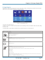
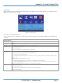
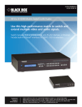
AVSC-7DA-HDMI Multi-Format AV Scaler with DisplayPort Scales analog video, S-Video, component video, BLACK VGA, DVI, HDMI, and DisplayPort videoBOX input signals into VGA or HDMI output signals. ® Supports resolutions of 480i/p, 720p, and 1080i/p. Customer Support Information Order toll-free in the U.S.: Call 877-877-BBOX (outside U.S. call 724-746-5500) FREE technical support 24 hours a day, 7 days a week: Call 724-746-5500 or fax 724-746-0746 Mailing address: Black Box Corporation, 1000 Park Drive, Lawrence, PA 15055-1018 Web site: www.blackbox.com • E-mail: [email protected] Trademarks Used in this Manual Trademarks Used in this Manual Black Box and the Double Diamond logo are registered trademarks of BB Technologies, Inc. Any other trademarks mentioned in this manual are acknowledged to be the property of the trademark owners. We‘re here to help! If you have any questions about your application or our products, contact Black Box Tech Support at 724-746-5500 or go to blackbox.com and click on “Talk to Black Box.” You’ll be live with one of our technical experts in less than 60 seconds. Page 2 724-746-5500 | blackbox.com FCC and IC RFI Statements Federal Communications Commission and Industry Canada Radio Frequency Interference Statements This equipment generates, uses, and can radiate radio-frequency energy, and if not installed and used properly, that is, in strict accordance with the manufacturer’s instructions, may cause interference to radio communication. It has been tested and found to comply with the limits for a Class A computing device in accordance with the specifications in Subpart B of Part 15 of FCC rules, which are designed to provide reasonable protection against such interference when the equipment is operated in a commercial environment. Operation of this equipment in a residential area is likely to cause interference, in which case the user at his own expense will be required to take whatever measures may be necessary to correct the interference. Changes or modifications not expressly approved by the party responsible for compliance could void the user’s authority to operate the equipment. This digital apparatus does not exceed the Class A limits for radio noise emission from digital apparatus set out in the Radio Interference Regulation of Industry Canada. Le présent appareil numérique n’émet pas de bruits radioélectriques dépassant les limites applicables aux appareils numériques de la classe A prescrites dans le Règlement sur le brouillage radioélectrique publié par Industrie Canada. 724-746-5500 | blackbox.com Page 3 NOM Statement Instrucciones de Seguridad (Normas Oficiales Mexicanas Electrical Safety Statement) 1. T odas las instrucciones de seguridad y operación deberán ser leídas antes de que el aparato eléctrico sea operado. 2. Las instrucciones de seguridad y operación deberán ser guardadas para referencia futura. 3. Todas las advertencias en el aparato eléctrico y en sus instrucciones de operación deben ser respetadas. 4. T odas las instrucciones de operación y uso deben ser seguidas. 5. E l aparato eléctrico no deberá ser usado cerca del agua—por ejemplo, cerca de la tina de baño, lavabo, sótano mojado o cerca de una alberca, etc. 6. E l aparato eléctrico debe ser usado únicamente con carritos o pedestales que sean recomendados por el fabricante. 7. El aparato eléctrico debe ser montado a la pared o al techo sólo como sea recomendado por el fabricante. 8. S ervicio—El usuario no debe intentar dar servicio al equipo eléctrico más allá a lo descrito en las instrucciones de operación. Todo otro servicio deberá ser referido a personal de servicio calificado. 9. El aparato eléctrico debe ser situado de tal manera que su posición no interfiera su uso. La colocación del aparato eléctrico sobre una cama, sofá, alfombra o superficie similar puede bloquea la ventilación, no se debe colocar en libreros o gabinetes que impidan el flujo de aire por los orificios de ventilación. 10. E l equipo eléctrico deber ser situado fuera del alcance de fuentes de calor como radiadores, registros de calor, estufas u otros aparatos (incluyendo amplificadores) que producen calor. 11. E l aparato eléctrico deberá ser connectado a una fuente de poder sólo del tipo descrito en el instructivo de operación, o como se indique en el aparato. 12. P recaución debe ser tomada de tal manera que la tierra fisica y la polarización del equipo no sea eliminada. 13. L os cables de la fuente de poder deben ser guiados de tal manera que no sean pisados ni pellizcados por objetos colocados sobre o contra ellos, poniendo particular atención a los contactos y receptáculos donde salen del aparato. 14. El equipo eléctrico debe ser limpiado únicamente de acuerdo a las recomendaciones del fabricante. 15. E n caso de existir, una antena externa deberá ser localizada lejos de las lineas de energia. 16. El cable de corriente deberá ser desconectado del cuando el equipo no sea usado por un largo periodo de tiempo. 17. Cuidado debe ser tomado de tal manera que objectos liquidos no sean derramados sobre la cubierta u orificios de ventilación. 18. S ervicio por personal calificado deberá ser provisto cuando: A: El cable de poder o el contacto ha sido dañado; u B: Objectos han caído o líquido ha sido derramado dentro del aparato; o C: El aparato ha sido expuesto a la lluvia; o D: El aparato parece no operar normalmente o muestra un cambio en su desempeño; o E: El aparato ha sido tirado o su cubierta ha sido dañada. Page 4 724-746-5500 | blackbox.com Safety Information Safety Information 1. S ave the carton and packing materials whether or not the unit arrives in good condition. If you ever need to ship the unit, use the original factory packing. 2. Read all documentation before operating your equipment. Retain all documentation for future reference. 3. Follow all instructions printed on the unit chassis for proper operation. 4. Do not spill water or other liquids into or on the unit, or operate the unit in liquid. 5. Make sure power outlets conform to the power requirements listed on the back of the unit. 6. D o not use the unit if the electrical power cord is frayed or broken. Route the power supply cords so that they are not likely to be walked on or pinched by items placed upon or against them. Pay particular attention to cords, plugs, convenience receptacles, and the points where they exit from the appliance. 7. A lways operate the unit with the AC ground wire connected to the electrical system ground. Be careful not to defeat the grounding of a piece of equipment. 8. V oltage must be the same as that printed on the rear of the unit. Damage caused by connection to improper AC voltage is not covered by warranty. 9. Power off and disconnect the unit from the voltage before connecting any equipment. 10. Do not leave the unit on unstable surfaces. 11. Do not use the unit near stoves, heat registers, radiators, or other heat-producing devices. 12. D o not block the fan intake or exhaust ports. Do not operate the equipment on a surface or in an environment that may impede the normal flow of air around the unit, such as a bed, rug, carpet, or completely enclosed rack. If the unit is used in extremely dusty or smoky environment, the unit should be periodically “blown free” of foreign matter. 13. D o not remove the cover. Removing the cover will expose you to potentially dangerous voltages. There are no user-serviceable parts inside. 14. Do not drive the inputs with a signal level greater than that required to drive the equipment to reach full output. 15. W hen you are not using the unit, unplug the power cord of the equipment from the outlet. 16. Refer servicing to qualified service personnel when: A. The power supply cord or the plug is damaged. B. Liquid has been spilled into the equipment. C. The equipment has fallen. D. The equipment has been exposed to rain. E. The equipment does not appear to operate normally, or exhibits a change in performance. F. The equipment has been dropped, or the enclosure damaged. 724-746-5500 | blackbox.com Page 5 Important Safety Instructions Important Safety Instructions To ensure the best from this product, read this manual carefully. Keep it for future reference. To reduce the risk of electric shock, do not remove the cover from the unit. There are no user-serviceable parts inside. Refer servicing to qualified personnel. To reduce the risk of fire, do not expose the unit to rain, water, or excessive moisture. Do not force switched or external connections. When moving the unit, disconnect the serial port connection first, then the power cable, and finally the interconnecting cables to other devices. Do not attempt to clean the unit with chemical solvents or aerosol cleaners, as this may damage the unit. Use a clean, dry cloth. Install this unit in a cool, dry place, away from sources of excessive heat, vibration, dust, moisture, and cold. Page 6 724-746-5500 | blackbox.com Table of Contents Table of Contents 1.Specifications..........................................................................................................................................................................8 2. Overview.............................................................................................................................................................................. 12 2.1Introduction.................................................................................................................................................................. 12 2.2Features........................................................................................................................................................................ 12 2.3 What’s Included........................................................................................................................................................... 12 2.4 Hardware Description................................................................................................................................................... 13 2.4.1 Front Panel........................................................................................................................................................ 13 2.4.2 Back Panel......................................................................................................................................................... 14 2.5 Typical Application........................................................................................................................................................ 17 3. Remote Controller................................................................................................................................................................ 18 3.1 IR Remote..................................................................................................................................................................... 18 3.2 IR Remote Custom and Data Codes (NEC Standard).................................................................................................... 19 4. IR Extender...........................................................................................................................................................................20 4.1 IR Extender Connection................................................................................................................................................20 4.2 IR Extender Package.....................................................................................................................................................20 5.Installation............................................................................................................................................................................ 21 6. On-Screen Display (OSD)......................................................................................................................................................22 6.1 OSD Options Overview.................................................................................................................................................22 6.2Picture..........................................................................................................................................................................23 6.3 Image Setup................................................................................................................................................................. 24 6.4 Image Properties..........................................................................................................................................................25 6.5 Video Wall....................................................................................................................................................................26 6.6Options.........................................................................................................................................................................27 7. RS-232 Protocol Commands.................................................................................................................................................28 7.1 AVSC-7DA-HDMI RS-232 Protocol and Commands......................................................................................................28 7.2 Ethernet TCP Setup Guide............................................................................................................................................29 7.3 Data String Format.......................................................................................................................................................30 7.4Commands................................................................................................................................................................... 31 Appendix. Video Timing List......................................................................................................................................................40 Appendix B. Troubleshooting.....................................................................................................................................................44 B.1 Contacting Black Box...................................................................................................................................................44 B.2 Shipping and Packaging...............................................................................................................................................44 724-746-5500 | blackbox.com Page 7 Chapter 1: Specifications 1. Specifications Technical Specifications Advanced Video Processing High-quality video and graphics scaling up and down Frame rate conversion Approvals CE, FCC, RoHS (2002/95/EC) Audio Input Signal Digital Audio (PCM), Stereo Audio Audio Output Signal 1x S/PDIF Digital Audio, 1x Analog Audio RH/LH, 1x HDMI Audio Chassis Material Metal Control IR remote control, RS-232, front panel push buttons Dimensions 11.96"H x 5.90"W x 1.73"D (30.4 x 15 cm x 1.1 cm) HDCP Support Automatic scanning of input/output status HDMI Cable Distance Max. 15 meters (49 feet), depending on cable quality HDMI Compliance HDMI 1.4a receiver and transmitter Infrared Frequency 38 KHz Input Resolution DVI/ HDMI/ Display Port, compliant with HDCP 2.0 Intelligent Color Adjustment Discrete RGB, color adjustment, hue, saturation sharpness, contrast, brightness, four preset color modes IR Extend Distance 300 meters (984 feet) line cable via IR extender Output Resolution Up to 1080p-60, 1920x1200 Power Supply Input: 100–240 VAC, 50/60 Hz Output: 12 VDC, 2 A Rackmount 19-inch panel type (1U-44L) Scaler Type 7 in/2 out HDMI Video Scaler Source Status Automatic scanning of input/output status System Control Box ID for easy independent control through IR, RS-232, and five selectable profiles settings for difference display. Ethernet control module with RJ-45 connector. ASCII control protocol over RS-232 and Ethernet. Temperature 32–100° F (0–32° C) Video Input Signal (1) Composite/(1) S-Video/(1) Component (1) VGA/(1) DVI/(1) HDMI/(1) DP Video Output Signal (1) VGA, (1) HDMI Video Wall Magnify, scroll, pan through all inputs Video wall function: Image split, cropping, and assign display location Pixel based overlap adjustment in all edges, up to 15x15 matrix displays Up to 2560 x 1600 input resolution via display port Weight Page 8 Shipping weight: 3.42 lb. (2.05 kg) 724-746-5500 | blackbox.com Chapter 1: Specifications Input Resolution Support Input Resolution Component 640 x 350 @ 85 Hz 480p/480i 640 x 400 @ 85 Hz 576p/576i 640 x 480 @ 60 Hz 720p 640 x 480 @ 72 Hz VGA 640 x 480 @ 75 Hz VGA 720 x 400 @ 70 Hz DOS 720 x 400 @ 85 Hz 1080p/1080i 800 x 600 @ 56 Hz SVGA VGA √ √ √ √ √ DVI HDMI DisplayPort √ √ √ √ √ √ √ √ √ √ √ √ √ √ √ √ √ √ √ √ √ √ √ √ √ √ 800 x 600 @ 60 Hz SVGA √ √ √ √ 800 x 600 @ 72 Hz SVGA √ √ √ √ 800 x 600 @ 75 Hz SVGA √ √ √ √ 832 x 624 @ 75 Hz SVGA √ √ √ √ 848 x 480 @ 59 Hz WVGA √ √ √ √ 848 x 480 @ 60 Hz WVGA √ √ √ √ 852 x 480 @ 60 Hz 480p √ 1024 x 768 @ 60 Hz XGA √ √ √ √ 1024 x 768 @ 70 Hz XGA √ √ √ 1024 x 768 @ 75 Hz XGA √ √ √ √ √ √ √ 1152 x 864 @ 75 Hz XGA+ √ 1280 x 720 @ 48 Hz HD 720 √ 1280 x 720 @ 50 Hz HD 720 √ √ √ √ 1280 x 720 @ 60 Hz WXGA √ √ √ √ √ 1280 x 768 @ 75 Hz WXGA √ √ √ 1280 x 768 @ 60 Hz WXGA √ √ √ 1280 x 800 @ 60 Hz WXGA √ √ √ 1280 x 800 @ 75 Hz WXGA √ √ √ 1280 x 960 @ 60 Hz SXGA √ √ √ 1280 x 1024 @ 60 Hz SXGA √ √ √ √ 1280 x 1024 @ 75 Hz SXGA √ √ √ √ 1360 x 768 @ 60 Hz SXGA √ √ √ √ 1360 x 768 @ 75 Hz SXGA √ 1366 x 768 @ 60 Hz WXGA √ 1400 x 788 @ 60 Hz WXGA+ √ 1400 x 1050 @ 60 Hz SXGA+ √ √ √ √ 1400 x 1050 @ 75 Hz SXGA+ √ √ √ √ 1400 x 1050 @ 60 Hz SXGA+ √ √ √ 1440 x 900 @ 60 Hz WXGA+ √ √ √ 1440 x 900 @ 75 Hz WXGA+ √ √ 1440 x 1050 @ 60 Hz SXGA+ √ √ √ √ 1600 x 1200 @ 60 Hz UXGA √ √ √ √ NOTE: A detailed resolution timing list is included in the Appendix. 724-746-5500 | blackbox.com Page 9 Chapter 1: Specifications Input Resolution Support (Continued) Input Resolution Component 1600 x 1200 @ 65 Hz UXGA 1600 x 1200 @ 70 Hz UXGA 1600 x 1200 @ 75 Hz UXGA 1680 x 1050 @ 60 Hz WSXGA+ VGA DVI HDMI DisplayPort √ √ √ √ 1792 x 1344 @ 60 Hz √ 1856 x 1392 @ 60 Hz √ √ √ √ √ √ √ 1920 x 1200 @ 60 Hz WUXGA 1920 x 1200 @ 60 Hz WUXGA √ 1920 x 1440 @ 60 Hz WUXGA √ 1920 x 1440 @ 75 Hz WUXGA √ 720 x 480p @ 59 Hz DVD “NTSC” √ √ 720 x 480p @ 59 Hz DVD “NTSC” √ √ √ 720 x 576p @ 50 Hz DVD “PAL” √ √ √ 720 x 576p @ 50 Hz DVD “PAL” √ √ √ 1280 x 720p @ 50 Hz HDTV 720p √ √ √ 1280 x 720p @ 60 Hz HDTV 720p √ √ √ 1280 x 720p @ 100 Hz HDTV 720p √ √ √ 1280 x 720p @ 120 Hz HDTV 720p √ √ √ 1920 x 1080p @ 24 Hz 1080p HD √ √ 1920 x 1080p @ 30 Hz 1080i HD √ √ 1920 x 1080p @ 50 Hz 1080p HD √ √ 1920 x 1080p @ 60 Hz 1080p HD √ √ 1920 x 1080p @ 24 Hz Full HD 1080p √ √ √ √ 2048 x 1280 @ 60 Hz 2560 x 1600 √ √ WQXGA NOTE: A detailed resolution timing list is included in the Appendix. Page 10 724-746-5500 | blackbox.com Chapter 1: Specifications Output Resolution Support Output Front Panel Buttons Resolution VGA HDMI OTHERS 720 x 480 √ √ 800 x 600 √ √ 1280 x 800 √ √ 1280 x 1024 √ √ 1360 x 768 √ √ 1400 x 1050 √ √ 1600 x 1200 √ √ XGA 1920 x 1200 √ √ WXGA 1024 x 768 √ √ 720p 1280 x 720 √ √ 1080p 1920 x 1080 √ √ NOTE: When you press the front panel button “OTHERS,” the scaler will automatically apply the resolution 1360 x 768. Continue pressing “OTHERS” to cycle through the following four resolutions: 1360 x 768 —> 1280 x 1024 —> 1600 x 1200 —> 1920 x 1200 NOTE: To select 720 x 480, 800 x 600, or 1280 x 800, open the OSD menu and go to “Image Properties” to adjust the settings in output mode. 724-746-5500 | blackbox.com Page 11 Chapter 2: Overview 2. Overview 2.1 Introduction The AVSC-7DA-HDMI is a video graphics scaler that accepts seven types of signals: analog video, S-Video, component video, VGA, DVI, HDMI, and DisplayPort signals. It scales the input signals into either VGA or HDMI signals, supporting higher full HD resolutions of 480i/p, 720p, and 1080i/p. The scaler is designed to solve problems of compatibility between source devices and monitors. Use it to deliver one single image on a TV wall. In addition to the front panel buttons and the IR remote control, users may control the scaler using a PC through the RS-232 serial port or Ethernet port. 2.2 Features • Compliant with HDMI 1.4, DVI 2.0, and HDCP 2.0. • Input support: Analog: analog video, S-Video, composite video, VGA; Digital: DVI, HDMI, and DisplayPort • Output support: VGA and HDMI 1080p with deep color 36-bit • Output audio support: S/PDIF, stereo audio • S upports a wide range of HD resolutions ranging from XGA to WUXGA 1920 x 1200 to HDTV/DTV resolutions 480i/480p, 576i/576p, 720p, 1080i, and 1080p. •C ompatible with all HDMI source devices, PC monitors, plasma HD displays, HDTVs, and audio receivers/amplifiers. • S upports intelligent color adjustment (discrete RGB color adjustment, hue, saturation, sharpness, contrast, brightness, and preset color modes). • Rackmountable: 19-inch ear rackmount. •V arious user interface control, including front-panel push buttons, IR wireless remote control, third-party RS-232 controller (via simple ASCII), and Ethernet with built-in Web browser. • Supports IR extender with maximum extend distance reaching 300 meters. • Supports TV wall function, allowing the image to be divided on multiple displays/monitors. • Includes 12-VDC power supply, universal-type switch, 100–240 VAC, 50/60 Hz. 2.3 What’s Included Your package should contain the following items. If anything is missing or damaged, contact Black Box Technical Support at 724-746-5500 or [email protected]. • Main console unit • IR remote controller • 19" ear mount bracket • IR extender receiver • CD-ROM containing this user manual in PDF format and IP changing software • RS-232 cable • 12-VDC, 2-A power supply, universal-type switch, 50/60 Hz, 100–240 VAC Page 12 724-746-5500 | blackbox.com Chapter 2: Overview 2.4 Hardware Description Figure 2-1 shows the front panel of the scaler. Table 2-1 describes its components. Figures 2-2 through 2-4 show the back panel of the scaler. Tables 2-2 through 2-4 describe its components. 2.4.1 Front Panel Figure 2-1. Front panel of the scaler. Table 2-1. Front panel components. Number in Figure 2-1 Component Description 1 Power switch The power switch turns the unit on and off. The LED lights blue to indicate that the switch is ON and receiving power. The scaler will remember the last setting during a power cycle. When turned ON again, it will automatically apply the setting last used. 2 Menu Press menu to open the on-screen display (OSD) interface. Press again to exit the menu. For guidance on the OSD options, refer to Chapter 7, OSD Instructions. 3 Enter Press enter to confirm your entries. 4 Arrow keys Use the arrow keys to move between the OSD options. Press the up key to enter the upper layer and the down key to enter the next layer. Press the left and right keys to select options in the same layer or change the value of a parameter. 5 IR sensor The IR sensor receives IR commands from the supplied remote controller or a third-party IR emitter. 6 Output select buttons Select the desired resolution supported by your display devices. Press “OTHERS” for resolutions other than XGA, WXGA, 720p, and 1080p. The button will light blue to indicate it is selected. Advanced resolution adjustment is an OSD option. 7 Input select buttons Select from one of the seven buttons the video signal to scale. The button will light blue to indicate it is selected. 724-746-5500 | blackbox.com Page 13 Chapter 2: Overview 2.4.2 Back Panel Figure 2-2. Back panel of the scaler. Table 2-2. Back panel components. Number in Figure 2-2 Component Description 1 DC power inlet/outlet The scaler has a DC power plug-pack input connector. Make sure the plugpack used is of an approved type and is the correct current, voltage output, and connector polarity: 12-VDC, 2-A power supply. Power jack: DC jack: Inner OD = 2.1 mm Outside OD = 5.5 mm Power input: 12 VDC, 2 A 2 Ethernet connection Connect a CAT5 cable to the Ethernet port to control the scaler from a computer. 8P8C/RJ-45 connector 3 RS-232 connection Connect a serial cable to the RS-232 port to control the scaler from a computer. DB9 female connector 4 Link Connect the link port for firmware updates. Terminal block connector 5 IR extender control Supports remote control via IR extender. Maximum extend distance reaches about 1000 feet (300 meters). IR extender jack: Female jack: Inner OD = 3.5 mm Page 14 Picture 724-746-5500 | blackbox.com Specifications Chapter 2: Overview Figure 2-3. Back panel of the scaler. Table 2-3. Back panel components (continued). Number in Figure 2-3 Component Description Picture Specifications 6 YPbPr + AR/AL audio input Connect a component video signal directly to the female RCA connector, which supports component video (YPbPr) to HDTV display devices. Connect the output port of your source audio device to the AR/AL inputs. Component video via (3) RCA female connectors Stereo audio via (2) RCA female connectors 7 VGA + VGA audio input Connect a VGA (RGBHV) signal to the HD15 female connector. Connect the output port of your source device to the audio input. VGA video jack: Female HD15 connector 8 DVI + DVI audio input Connect a DVI signal to the digital video connector. Connect the output port of your source audio device to the audio input. Female DVI connector 9 HDMI input Connect an HDMI direct digital video/ audio signal link to the HDMI connector, which supports HDMI digital video/audio and DVI digital video sources. HDMI female jack 10 DisplayPort input Connect a DisplayPort signal to the DP port, which supports digital video and audio. Display port digital video and audio connector. 724-746-5500 | blackbox.com Page 15 Chapter 2: Overview Figure 2-4. Back panel of the scaler. Table 2-4. Back panel components (continued). Number in Figure 2-4 Component Description 11 Video + AR/AL audio input Connect a composite video signal to the RCA connector. Connect the output port of your source audio device to the AR/AL inputs. Female RCA connector Stereo audio (AR/AL) via (1) 3.5-mm earphone jack connector Connect an S-Video signal to the connector. Connect the output port of your source audio device to the AR/AL inputs. Mini-DIN connector Stereo audio (AR/AL) via (1) 3.5-mm earphone jack connector 12 S-Video + AR/AL audio input Picture Specifications NOTE: W ith (1) female phone jack for each channel. NOTE: W ith (1) female phone jack for each channel. 13 SPDIF Connect the digital audio output. Female RCA connector. 14 VGA output Connect a VGA (RGBHV) to the VGA connector. VGA video jack: Female HD15 connector 15 HDMI output Connect an HDMI direct digital video/ audio signal link to this female HDMI connector, which supports HDMI digital video/audio and DVI digital video sources. HDMI digital video/audio connector HDMI female connector Page 16 724-746-5500 | blackbox.com NOTE: W ith proper adapters, the scaler can be used with DVI digital video signals and is HDCP compliant. Chapter 2: Overview 2.5 Typical Application Audio out Composite plus audio in Audio amplifier Ethernet RS-232 HDMI HDTV Component in HDMI out PC/Ethernet RS-232 control VGA out DVI plus audio in HDMI in Blu-ray DVD DisplayPort in Mac Figure 2-5. Multi-Format AV Scaler with DisplayPort. 724-746-5500 | blackbox.com Page 17 Chapter 3: IR Remote 3. IR Remote 3.1 Remote Control Before connecting anything to the scaler, observe the following: • Make sure the voltage supply matches the label on the supplied plug-pack (±10%). • Make sure the power switch is off. • Make sure that all system grounds are connected to a common point. • Avoid powering the device within a system of multiple power sources that are separated by a large distance. • Connect all audio/video source and display devices. • Power on all source and display audio-visual devices. • T o yield video/audio to an output, select the input source by using the front panel input buttons, the supplied IR remote control, or through the RS-232 serial communication port. • When powering on, the scaler will automatically apply the setting last used. NOTE: For how to to use the on-screen display (OSD) options, go to Chapter 7, OSD Instructions, in this manual. Table 3-1. IR remote control key. Page 18 Number in Figure 3-1 Description 1, 2 Power ON and OFF: Turn the scaler on or off. 3 Mute: Stop playing sounds. 4 Source (HDMI, VGA, DVI, DP, YPbPr, Video, S-Video): Select your input signal type. 5 Enter: Confirm your selection/enter the next layer of OSD options. 6 Arrow keys: Move up, down, left, or right between the OSD options. Use the left and right arrow keys to adjust the value of a parameter. Use the down key to enter the next layer of options and the up key to move back. 7 Return: Return to the upper layer of OSD options. 8 Menu: Open the OSD menu. 9 Info: Check the connection status of input/ output/RS-232/Ethernet ports. 10 Exit: Leave the OSD menu. 11 Output (XGA, WXGA, 720p, 1080p, and others): Select the desired output resolution supported by your display device. 12 OSD timeout: Adjust the OSD menu display time. 13 Video wall: Open the video wall options. Figure 3-1. IR remote. 724-746-5500 | blackbox.com Chapter 3: IR Remote 3.2 IR Remote Custom and Data Codes (NEC Standard) How to set up IR codes: Custom Code: 20 DF Power on: 20DF 5DA2 Power off: 20DF 5EA1 Mute: 20DF 02FD HDMI: 20DF 1FE0 VGA: 20DF 0AF5 DVI: 20DF 50AF DP: 20DF 59A6 YPbPr: 20DF 58A7 Video: 20DF 5AA5 S-Video: 20DF 5BA4 Return: 20DF 11EE Menu: 20DF 19EA Info: 20DF 1BE4 Exit: 20DF 5CA3 Enter: 20DF 51AE Up: 20DF 44BB Right: 20DF 48B7 Left: 20DF 1CE3 Down: 20DF 1DE2 XGA: 20DF 08F8 WXGA: 20DF 4BB4 720p: 20DF 05FA 1080p: 20DF 06F9 Others: 20DF 03FC OSD timeout: 20DF 15EA Video wall: 20DF 15EB Example 1: Select input VGA and output HDMI. The IR data code: 20DF 0AF5 20DF 07F8 Example 2: Open OSD—>move right—>move down to next layer—>enter to confirm selection. The IR data code: 20DF 15EA 20DF 48B7 20DF 1DE2 20DF 51AE 724-746-5500 | blackbox.com Page 19 Chapter 4: IR Extender 4. IR Extender 4.1 IR Extender Connection Rear panel IR extender port Room Figure 4-1. IR extender connection. NOTE: When you plug the external IR extender into the scaler, the front panel IR receiver remains active. 4.2 IR Extender Package How to Set Up the IR Extender Components Figure 4-2. Setting up thte IR extender components. Page 20 724-746-5500 | blackbox.com Chapter 5: Installation 5. Installation Control Ports: 1. Front panel—function key press buttons. 2. IR remote—IR remote controller. 3. RS-232 interface—RS-232 interface system. 4. Ethernet—Ethernet interface system. Inputs 1–7 Port Source Signals: Component video, AV, DVI, HDMI, DisplayPort (5 input ports connected) Outputs 1–2 Port Display Signals: VGA, HDMI NOTE: The Multi-Format AV Scaler with DisplayPort supports seven inputs and two outputs, control IR, and RS-232 interface system ports. 724-746-5500 | blackbox.com Page 21 Chapter 6: On-Screen Display (OSD) 6. On-Screen Display (OSD) 6.1 OSD Options Overview Table 6-1. OSD options. Layer 1 Layer 2 Picture Brightness Layer 3 Contrast Hue Saturation Sharpness Image Setup Automatic Manual Clock/Phase/Save Horizontal Position Vertical Position Image Properties Video Wall Options Color Preset Mode/Custom Input Signal DVI/HDMI/VGA/DisplayPort/Component/Composite/S-Video Scaling Original AR/Full Screen Output Mode 720 x 480, 800 x 600, 1280 x 800, 1280 x 1024, 1360 x 768, 1400 x 1050, 1600 x 1200, 1024 x 768, 1280 x 768, 1280 x 720, 1920 x 1080 Zoom Horizontal Zoom/Vertical Zoom Pan Horizontal Pan/Vertical Pan Overlap Left/Right/Top/Bottom (Edges)/Reset Information Language English Reset Reset All/Reset Video Wall Accessibility Button Repeat Rate (off, default, slow)/Menu Timeout/Logo Timeout Setting Mute Box ID Profile Network (serial port, Ethernet) Page 22 724-746-5500 | blackbox.com Chapter 6: On-Screen Display (OSD) 6.2 Picture Picture allows you to digitally adjust the brightness, contrast, hue, saturation, and sharpness of the images. An unlit icon suggests the function is not available. To enable it, the unit color must be set in custom mode. Go to the third icon in the first layer to change the setting in color: Image properties—>color—>custom—>save. Be sure to save your setting. Otherwise, the value will not be set. Figure 6-1. Picture icon. • Layer one, the first icon from left. •C hoose the icon and use the down arrow key to open the next layer, which has five options: brightness, contrast, hue, saturation, and sharpness. • The hue, saturation, and broadcast icons light only when AV, S-Video, or component video signals are present on the scaler. Table 6-2. Picture options. Icon Description Brightness: Use arrow key right and left to adjust the value. Contrast: Use arrow key right and left to adjust the value. Hue: Use arrow key right and left to adjust the value. Adjustable only when the unit receives valid AV, S-Video, or component video signals. Saturation: Use arrow key right and left to adjust the value. Adjustable only when the unit receives valid AV, S-Video, or component video signals. Sharpness: Use arrow key right and left to adjust the value. Adjustable only when the unit receives valid AV, S-Video, or component video signals. 724-746-5500 | blackbox.com Page 23 Chapter 6: On-Screen Display (OSD) 6.3 Image Setup To enable the image setup, a valid VGA signal must be present on the scaler. An illuminated icon indicates the presence of a VGA signal. Figure 6-2. Image setup icon. • First layer, the second icon from the left. •C hoose the icon and use the down arrow key to open the second layer, which has four options: automatic, manual, horizontal position, and vertical position. Table 6-3. Image setup. Icon Description Automatic: AVSC-7DA-HDMI reads the input signal and automatically sets the optimal value for the output. Manual: Clock/Phase /Save Horizontal Position Move the image to the right or left. Vertical Position Move the image up or down. Page 24 724-746-5500 | blackbox.com Chapter 6: On-Screen Display (OSD) 6.4 Image Properties Image properties allow you to change color, select input signal, adjust scaling, and change output resolution. Under the output mode, you can select resolutions not listed on the front panel button. Figure 6-3. Image properties icon. • Layer one, the third icon from left. • Choose the icon and use the down arrow key to open up the second layer, which has four options: color, input signal, scaling, and output mode. • Setting the color in custom mode can enable the Picture function (layer one, the first icon from left). Table 6-4. Image properties. Icon Description Color Preset Mode: Standard, RGB, warm, cold Custom: Red, Green, Blue, Save Input Signal DVI, HDMI, VGA, DisplayPort, Component, Composite Video, S-Video Scaling Original AR, full screen Output Mode Select one desired output resolution from the following 11 choices: Others, 720 x 480, 800 x 600, 1280 x 800, 1280 x 1024, 1360 x 768, 1400 x 1050, 1600 x 1200, 1920 x 1200 XGA: 1024 x 768 WXGA: 1280 x s 720p: 1280 x 720 1080p: 1920 x 1080 When you press the front panel button “Others,” the scaler will automatically apply the resolution 1360 x 768. Users may continue pressing “Others” to cycle through the following four resolutions: 1360 x 768 —> 1280 x 1024 —> 1600 x 1200 —> 1920 x 1200 724-746-5500 | blackbox.com Page 25 Chapter 6: On-Screen Display (OSD) 6.5 Video Wall The AVSW-7DA-HDMI scaler can send divided images on multiple display devices and build a video wall of, for example, 1x2, 2x2, or 10x10. A video wall of 15x15 is the maximum size the scaler can generate. NOTE: An AVSW-7DA-HDMI is required for each output. Users may arrange the position and adjust the size of each image block under the TV WALL function. Figure 6-4. Video Wall icon. • Layer one, the third icon from the left. • Choose the TV wall icon, use the down arrow key to open the next layer, which has three options: zoom, pan, and overlap. Table 6-5. Video wall. Parameter Description Zoom Use right/left key to adjust the value of the parameter. Horizontal zoom: enlarge the image on the left and right ends. Vertical zoom: enlarge the image upwardly and downwardly. Pan Arrange the relative position of the image in the TV wall: assign the number of displays horizontally and vertically connected. Then, assign numbers to indicate relative position. Two examples of TV walls are shown below. 3x2 TV wall (Horiztonal: 3; Vertical: 2) Display No. 4 should be assigned: Horizontal Zoom = 1 Vertical Zoom = 2 Display No. 5 should be assigned: Horizontal Zoom = 2 Vertical Zoom = 2 Overlap Align the overlapping images for visual continuum. Move the image up, down, or to left, right by adjusting the parameters of the top edge, bottom edge, left edge, and right edge. To return to the original setting, press “Reset.” Page 26 724-746-5500 | blackbox.com Chapter 6: On-Screen Display (OSD) 6.6 Options Options allows you to check the connection status, change menu language, return to factory defaults, save settings, and make adjustments to the OSD menu settings. Figure 6-7. Options icon. • Layer one: the fifth icon from the left. • P ress the down arrow key to open up the second layer, which has five options: information, language, reset, accessibility, and setting. Table 6-6. Options. Parameter Description Information Check the connection status of the input/output ports, the model name, the connection status of RS-232/Ethernet ports, and the firmware version. Language Change the OSD language to English, Simplified Chinese, or Traditional Chinese. Reset Return to the factory default setting. Reset all: Reset all options. Reset video wall: Reset all the options relating to video wall function only. Accessibility Button repeat rate: Adjust the unit response time when the Menu button is pressed. Off: Press the “Menu” button, and the menu shows up/disappears once. Default: Return to the factory default setting. Slow: Press the “Menu” button and hold it on for longer than a few seconds, and the unit will take more time than the default to respond. Menu timeout: Adjust the length of time the OSD menu stays on screen. On: The OSD menu will disappear after a period of time. You can lengthen or shorten the display time. Off: Stop the OSD menu from disappearing automatically. When the function is turned off, the OSD menu will not disappear until you press the “Menu” button again. Logo timeout: Adjust the length of time the logo stays on screen when the unit is turned on. Setting Mute: Stop playing sounds. Box ID: Check the ID of the unit. Profile: Save and reload the settings. The unit can memorize a total of five different settings. Network: Serial port, Ethernet. 724-746-5500 | blackbox.com Page 27 Chapter 7: RS-232 Protocol Commands 7. RS-232 Protocol Commands 7.1 AVSC-7DA-HDMI RS-232 Protocol and Commands Figure 7-1. RS-232 cable pin lines. 1. Transmission rate: 9600 bps 2. Data format: 8 data bits, no parity, 1 start bit, and 1 stop bit 3. Flow control: None Also known as 9600, n, 8, 1. Figure 7-2. COM1 properties and ASCII setup screens. Page 28 724-746-5500 | blackbox.com Chapter 7: RS-232 Protocol Commands 7.2 Ethernet TCP Setup Guide The Ethernet (TCP) port allows control of the unit via a computer by redirecting serial commands (COM port) to the unit’s IP address. To connect to the unit: 1. Set your PC within the same subnet of the unit (default address 192.168.0.3; default netmask 255.255.255.0). 2. Open up a telnet connection to the unit’s IP address with port 5000. 3. Send commands as you would with serial. To change the network settings of the unit: 1. Set your PC within the same Class C subnet of the unit. a. For example, if the unit’s default IP address is 192.168.0.3, the PC’s IP address could be 192.168.0.5. b. Set your PC’s netmask to 255.255.255.0. 2. Run the software included on the CD that came with the unit. 3. Click the search button and select your unit when it is found. 4. Change the unit’s network setting as desired and submit. To change your computer’s network settings: 1. Set up your computer in the same network of the unit. 2. Go to “Start” and click on “Control Panel.” 3. Double-click on “Network Connections.” 4. Click on “Properties.” 5. Click to select “Internet protocol (TCP/IP)” and click “Properties.” Figure 7-3. Properties selected. Figure 7-4. Internet protocol selected. 724-746-5500 | blackbox.com Page 29 Chapter 7: RS-232 Protocol Commands 7.3 Data String Format The data string contains four elements. [Command] [ ] [Data] [;] The format is: 1. Command 2. Space 3. Data 4. ; There is a single space after the command and before the data string. The data string must conclude with a semicolon “;” (without the quotation marks). All text is full ASCII code and is not case-sensitive. LINK is the same as Link. You can use either capital letters or lower-case letters and get the same result. The Link command must be sent first. This establishes a communications link between an external controller (or computer) and the device you wish to control. When you have an established link, communication via the IR port is disabled. The front panel remains operational. The format is: LINK 01; This will establish the link. Your commands: LINK 00; This will terminate the link. Devices that are firmware version x.x or higher will return a status. Status is command dependent. For example: Response: [SKU] [ ] [Status] [;]| The status is a two-digit numerical code. Specific details are discussed later in this document. NOTE: If at any time the AVSC-7DA-HDMI receives an invalid command, a response of “AVSC-7DA-HDMI 01” will be returned. Page 30 724-746-5500 | blackbox.com Chapter 7: RS-232 Protocol Commands 7.4 Commands NOTE: Not all commands are supported on all devices. Table 8-1. Commands. Item Command Description 1 Key Set OSD key 2 Power Set/check the power status. 3 Mute Set/check the mute status. 4 Source Set/check the source status. 5 Resolution Set/check the resolution status. 6 Brightness Set/check the brightness status from the OSD. 7 Contrast Set/check the contrast status from the OSD. 8 Hue Set/check the hue from the OSD. 9 Saturation Set/check the saturation status from the OSD. 10 Sharpness Set/check the sharpness status from the OSD. 11 Auto Set/check the auto adjustment status from the OSD. 12 H-Zoom Set/check the H-zoom status from the OSD. 13 V-Zoom Set/check the V-zoom status from the OSD. 14 H-Pan Set/check the H-pan status. 15 V-Pan Set/check the V-pan status. 16 Overlap–L Set/check the overlap-L status from the OSD. 17 Overlap-R Set/check the overlap-R status from the OSD. 18 Overlap-T Set/check the overlap-T status from the OSD. 19 Overlap-B Set/check the overlap-B status from the OSD. 20 Language Set/check the language status from the OSD. 21 Reset Set/check the reset status from the OSD. 22 Button Set/check the button status from the OSD. 23 Timeout Set/check the timeout status from the OSD. Function Command Response Description Set Key Key +000; AVSC-7DA-HDMI 00; Set Menu Key Key +001; AVSC-7DA-HDMI 00; Set Up Key Key +002; AVSC-7DA-HDMI 00; Set Down Key Key +003; AVSC-7DA-HDMI 00; Set Left Key Key +004; AVSC-7DA-HDMI 00; Set Right Key Key +005; AVSC-7DA-HDMI 00; Set Enter Key 1. Key 724-746-5500 | blackbox.com Page 31 Chapter 7: RS-232 Protocol Commands 2. Power Function Command Response Description Power OFF Power +000; AVSC-7DA-HDMI 00; Power OFF Power ON Power +001; AVSC-7DA-HDMI 00; Power ON Check the status of condition Power ?; Power +000; Power OFF Power +001; Power ON 3. Mute Function Command Response Description Mute OFF Mute +000; AVSC-7DA-HDMI 00; Mute OFF Mute ON Mute +001; AVSC-7DA-HDMI 00; Mute ON Check the Mute status Mute ?; Mute +000; Mute OFF Mute +001; Mute ON 4. Source Function Command Response Description Set Source Source +000; AVSC-7DA-HDMI 00; Source set to VGA Source +001; AVSC-7DA-HDMI 00; Source set to DVI Source +002; AVSC-7DA-HDMI 00; Source set to HDMI Source +003; AVSC-7DA-HDMI 00; Source set to DP Source +004; AVSC-7DA-HDMI 00; Source set to YPbPr Source +005; AVSC-7DA-HDMI 00; Source set to video Source +006; AVSC-7DA-HDMI 00; Source set to S-Video Function Command Response Description Check Source Source ?; Source +000; Source set to DVI Source +001; Source set to HDMI Source +002; Source set to VGA Source +003; Source set to DP Source +004; Source set to YPbPr Source +005; Source set to video Source +006; Source set to S-Video Page 32 724-746-5500 | blackbox.com Chapter 7: RS-232 Protocol Commands 5. Resolution Function Command Response Description Set Resolution Resolution +000; AVSC-7DA-HDMI 00; Set resolution to 720 x 480, 60 Hz Resolution +001; AVSC-7DA-HDMI 00; Set resolution to 1280 x 720, 60 Hz Resolution +002; AVSC-7DA-HDMI 00; Set resolution to 1920 x 1080, 60 Hz Resolution +003; AVSC-7DA-HDMI 00; Set resolution to 800 x 600, 60 Hz Resolution +004; AVSC-7DA-HDMI 00; Set resolution to 1024 x 768, 60 Hz Resolution +005; AVSC-7DA-HDMI 00; Set resolution to 1280 x 800, 60 Hz Resolution +006; AVSC-7DA-HDMI 00; Set resolution to 1280 x 1024, 60 Hz Resolution +007; AVSC-7DA-HDMI 00; Set resolution to 1360 x 768, 60 Hz Resolution +008; AVSC-7DA-HDMI 00; Set resolution to 1400 x 1050, 60 Hz Resolution +009; AVSC-7DA-HDMI 00; Set resolution to 1600 x 1200, 60 Hz Resolution +010; AVSC-7DA-HDMI 00; Set resolution to 1920 x 1200, 60 Hz Function Command Response Description Check Resolution Resolution ?; Resolution +000; Resolution is 720 x 480, 60 Hz Resolution +001; Resolution is 1280 x 720, 60 Hz Resolution +002; Resolution is 1920 x 1080, 60 Hz Resolution +003; Resolution is 800 x 600, 60 Hz Resolution +004; Resolution is 1024 x 768, 60 Hz Resolution +005; Resolution is 1280 x 800, 60 Hz Resolution +006; Resolution is 1280 x 1024, 60 Hz Resolution +007; Resolution is 1360 x 768, 60 Hz Resolution +008; Resolution is 1400 x 1050, 60 Hz Resolution +009; Resolution is 1600 x 1200, 60 Hz Resolution +010; Resolution is 1920 x 1200, 60 Hz 6. Brightness Function Command Variables Set Brightness BRIGHTNESS XXXX; AVSC-xxxx = Brightness number +000–+100 Command Example Response Description BRIGHTNESS +015; AVSC-7DA-HDMI 00; Set Brightness to 15. Function Command Response Description Check Brightness BRIGHTNESS ?; BRIGHTNESS +001; Brightness setting is 1. BRIGHTNESS +015; Brightness setting is 15. 724-746-5500 | blackbox.com Page 33 Chapter 7: RS-232 Protocol Commands 7. Contrast Function Command Variables Set Contrast CONTRAST XXXX; AVSC-xxxx = Contrast number +000–+100 Command Example Response Description CONTRAST +015; AVSC-7DA-HDMI 00; Set Contrast to 15. Function Command Response Description Check Contrast CONTRAST ?; CONTRAST +001; Contrast setting is 1. CONTRAST +015; Contrast setting is 15. 8. Hue Function Command Variables Set Hue HUE XXXX; AVSC-xxxx = Hue number +000–+100 Command Example Response Description HUE +015; AVSC-7DA-HDMI 00; Set Hue to 15. Function Command Response Description Check Hue HUE ?; HUE +001; Hue setting is 1. HUE +015; Hue setting is 15. 9. Saturation Function Command Variables Set Saturation SATURATION XXXX; AVSC-xxxx = Saturation number +000–+100 Command Example Response Description SATURATION +015; AVSC-7DA-HDMI 00; Set Saturation to 15. Function Command Response Description Check Saturation SATURATION ?; SATURATION +001; Saturation setting is 1. SATURATION +015; Saturation setting is 15. Page 34 724-746-5500 | blackbox.com Chapter 7: RS-232 Protocol Commands 10. Sharpness Function Command Variables Set Sharpness SHARPNESS XXXX; AVSC-xxxx = Sharpness number +000–+100 Command Example Response Description SHARPNESS +015; AVSC-7DA-HDMI 00; Set Sharpness to 15. Function Command Response Description Check Sharpness SHARPNESS ?; SHARPNESS +001; Sharpness setting is 1. SHARPNESS +015; Sharpness setting is 15. 11. Auto Function Command Response Description Set Auto Auto +001; AVSC-7DA-HDMI 00; Set VGA auto adjustment. Function Command Variables Set H-zoom H-ZOOM XXXX; xxxx = H zoom number +000 – +009 Command Example Response Description H-ZOOM +001; AVSC-7DA-HDMI 00; Set H-Zoom to 1. Function Command Response Description Check H-zoom H-ZOOM?; H-ZOOM +001; H-zoom setting is 1. 12. H-Zoom 724-746-5500 | blackbox.com Page 35 Chapter 7: RS-232 Protocol Commands 13. V-Zoom Function Command Variables Set V-zoom V-ZOOM XXXX; xxxx = V zoom number +000 – +009 Command Example Response Description V-ZOOM +001; AVSC-7DA-HDMI 00; Set V-Zoom to 1. Function Command Response Description Check V-zoom V-ZOOM?; V-ZOOM +001; V-zoom setting is 1. Function Command Variables Set H-Pan H-PAN XXXX; xxxx = H-Pan number +000 – +009 Command Example Response Description H-PAN +001; AVSC-7DA-HDMI 00; Set H-Pan to 1. Function Command Response Description Check H-Pan H-PAN?; H-PAN +001; H-Pan setting is 1. Function Command Variables Set V-Pan V-PAN XXXX; xxxx = V-Pan number +000 – +009 Command Example Response Description V-PAN +001; AVSC-7DA-HDMI 00; Set V-Pan to 1. Function Command Response Description Check V-Pan V-PAN?; V-PAN +001; V-Pan setting is 1. 14. H-Pan 15. V-Pan Page 36 724-746-5500 | blackbox.com Chapter 7: RS-232 Protocol Commands 16. Overlap—L Function Command Variables Set Overlap Left Edge OVERLAP-L XXXX; xxxx = Overlap-L number +-600– +600 Command Example Response Description OVERLAP-L+050; AVSC-7DA-HDMI 00; Set Overlap-L to +50. Function Command Response Description Check Overlap-L OVERLAP-L?; OVERLAP-L +050; Overlap-L setting is +50. Function Command Variables Set Overlap Right Edge OVERLAP-R XXXX; xxxx = Overlap-R number +-600– +600 Command Example Response Description OVERLAP-R +050; AVSC-7DA-HDMI 00; Set Overlap-R to +50. Function Command Response Description Check Overlap-R OVERLAP-R?; OVERLAP-R +050; Overlap-R setting is +50. Function Command Variables Set Overlap Top Edge OVERLAP-T XXXX; xxxx = Overlap-T number +-600– +600 Command Example Response Description OVERLAP-T +050; AVSC-7DA-HDMI 00; Set Overlap-R to +50. Function Command Response Description Check Overlap-T OVERLAP-T?; OVERLAP-T +050; Overlap-T setting is +50. 17. Overlap—R 18. Overlap—T 724-746-5500 | blackbox.com Page 37 Chapter 7: RS-232 Protocol Commands 19. Overlap—B Function Command Variables Set Overlap Bottom Edge OVERLAP-B XXXX; xxxx = Overlap-B number +-600– +600 Command Example Response Description OVERLAP-B +050; AVSC-7DA-HDMI 00; Set Overlap-B to +50. Function Command Response Description Check Overlap-B OVERLAP-B?; OVERLAP-B +050; Overlap-B setting is +50. Function Command Response Description Set Language LANGUAGE +000; AVSC-7DA-HDMI 00; Set language to English. LANGUAGE +001; AVSC-7DA-HDMI 00; Set language to simplified Chinese. LANGUAGE +002; AVSC-7DA-HDMI 00; Set language to traditional Chinese. Function Command Response Description Check Language Language ?; LANGUAGE +000; Language is English. LANGUAGE +001; Language is simplified Chinese. LANGUAGE +002; Language is traditional Chinese. 20. Language 21. Reset Function Command Response Description Set Reset RESET +001; AVSC-7DA-HDMI 00; Reset all settings. RESET +002; AVSC-7DA-HDMI 00; Reset video wall settings. Function Command Response Description Set button BUTTON +000; AVSC-7DA-HDMI 00; Set button to repeat rate off. BUTTON +001; AVSC-7DA-HDMI 00; Set button to repeat rate default. BUTTON +002; AVSC-7DA-HDMI 00; Set button to repeat rate slow. Function Command Response Description Check button Button?; BUTTON +000; Button is repeat rate off. BUTTON +001; Button is repeat rate default. BUTTON +002; Button is repeat rate slow. 22. Button Page 38 724-746-5500 | blackbox.com Chapter 7: RS-232 Protocol Commands 23. Timeout Function Command Variables Set TimeOut TIMEOUT XXXX; xxxx = Timeout number +000 – +060 Command Example Response Description TIMEOUT +015; AVSC-7DA-HDMI 00; Set timeout to 15 seconds. Function Command Response Description Check Timeout TIMEOUT?; TIMEOUT +001; Timeout setting is 1 second. TIMEOUT +015; Timeout setting is 15 seconds. 724-746-5500 | blackbox.com Page 39 Appendix A: Video Timing Lists Appendix A. Video Timing Lists Table A-1. Video Timing List (HDMI). Resolution H. Freq. (kHz) V. Freq. (Hz) Pixel Clock (MHz) H. Total Pixel H. Display Pixel H. Front Porch H. Sync. Width H. Sync. Pol. V. Total Lines V. Display Lines V. Front Porch V. Sync. Width V. Sync. Pol. 640 x 480 @60 Hz 31.484 59.97 25.1875 800 640 16 96 N 525 480 10 2 N 640 x 480 @72 Hz 37.861 72.809 31.5 832 640 24 40 N 520 480 9 3 N 640 x 480 @75 Hz 37.5 75 31.5 840 640 16 64 N 500 480 1 3 N 720 x 400 @70 Hz 31.458 70.063 28.3125 900 720 16 108 N 449 400 13 2 P 800 x 600 @56 Hz 35.156 56.25 36 1024 800 24 72 P 625 600 1 2 P 800 x 600 @60 Hz 37.879 60.317 40 1056 800 40 128 P 628 600 1 4 P 800 x 600 @72 Hz 48.077 72.188 50 1040 800 56 120 P 666 600 37 6 P 800 x 600 @75 Hz 46.875 75 49.5 1056 800 16 80 P 625 600 1 3 P 848 x 480 @59 Hz 29.83 59.659 31.5 1056 848 23 80 N 500 480 3 5 P 848 x 480 @60 Hz 31.02 60 33,75 1088 848 16 112 P 517 480 6 8 P 1024 x 768 @60 Hz 48.363 60.004 65 1344 1024 24 135 N 806 768 3 6 N 1024 x 768 @70 Hz 56.476 70.069 75 1328 1024 24 136 N 806 768 3 6 N 1024 x 768 @75 Hz 60.023 75.029 78.75 1312 1024 16 96 P 800 768 1 3 P 1152 x 864 @75 Hz 67.5 75 108 1600 1152 64 128 P 900 864 1 3 P 1280 x 720 @48 Hz 35.539 47.961 58 1632 1280 48 128 N 741 720 1 3 P 1280 x 720 @50 Hz 39.618 49.822 60.25 1632 1280 48 128 N 741 720 1 3 P 1280 x 720 @60 Hz 44.621 59.814 74.25 1664 1280 56 136 N 746 720 1 3 P 1280 x 768 @60 Hz 47.396 59.995 68.25 1440 1280 48 32 P 790 768 3 7 N 1280 x 768 @60 Hz 47.776 59.87 79.5 1664 1280 64 128 N 798 768 3 7 P 1280 x 768 @75 Hz 60.289 74.893 102.25 1696 1280 80 128 N 805 768 3 7 P 1280 x 800 @60 Hz 49.702 59.81 83.5 1680 1280 72 128 N 831 800 3 6 P 1280 x 700 @75 Hz 62.795 74.934 106.5 1696 1280 80 128 n 838 800 3 6 P 1280 x 960 @60 Hz 60 60 108 1800 1280 96 112 P 1000 960 1 3 P 1280 x 1024 @60 Hz 63.981 60.02 108 1688 1280 48 112 P 1066 1024 1 3 P 1280 x 1024 @75 Hz 79.976 72.025 135 1688 1280 16 144 P 1066 1024 1 3 P 1360 x 768 @60 Hz 47.712 60.015 85.5 1792 1360 64 112 P 795 768 3 6 P 1360 x 768 @60 Hz 48 60 72 1500 1366 13 56 P 800 768 1 3 P 1400 x 1050 @60 Hz 64.744 59.948 101 1560 1400 48 32 P 1080 1050 3 4 N 1400 x 1050 @60 Hz 65.317 59.978 121.75 1864 1400 88 144 N 1089 1050 3 4 P 1400 x 1050 @75 Hz 82.278 74.867 156 1896 1400 104 144 N 1099 1050 3 4 P 1440 x 900 @60 Hz 55.935 59.887 106.5 1904 1440 80 152 N 934 900 3 6 P 1440 x 900 @75 Hz 70.506 74.847 136.5 1936 1440 96 152 N 942 900 3 6 P 1440 x 1050 @60 Hz 65.234 59.903 125.25 1829 1440 88 152 N 1089 1050 3 10 N 1600 x 1200 @60 Hz 75 60 162 2160 1600 64 192 P 1250 1200 1 3 P 1680 X 1050 @60 Hz 65.402 60.057 146.5 2240 1680 104 176 N 1089 1020 2 6 P 1920 x 1200 @60 Hz 74.038 59.95 154 2080 1920 48 32 P 1235 1200 3 6 N 720 x 480p @59 Hz 31.469 59.94 27 858 720 16 62 N 525 480 9 6 N 720 x 480p @59 Hz 31.469 59.94 27 858 720 16 62 N 525 480 9 6 N 720 x 576p @50 Hz 31.25 50 27 864 720 12 64 N 625 576 5 5 N 720 x 576p @50 Hz 31.25 50 27 864 720 12 64 N 625 576 5 5 N 1280 x 720p @50 Hz 37.5 50 74.25 1980 1280 440 40 P 750 720 5 5 P Page 40 724-746-5500 | blackbox.com Appendix A: Video Timing Lists Table A-1 (Continued). Video Timing List (HDMI). Resolution H. Freq. (kHz) V. Freq. (Hz) Pixel Clock (MHz) H. Total Pixel H. Display Pixel H. Front Porch H. Sync. Width H. Sync. Pol. V. Total Lines V. Display Lines V. Front Porch V. Sync. Width V. Sync. Pol. 1280 x 720p @60 Hz 45 60 74.25 1650 1280 110 40 P 750 720 5 5 P 1280 x 720p @100 Hz 75 100 148.5 1980 1280 440 40 P 750 720 5 5 P 1280 x 720p @120 Hz 90 120 148.5 1650 1280 110 40 P 750 720 5 5 P 1920 x 108p @24 Hz 27 24 74.25 2750 1920 638 44 P 1125 1080 4 5 P 1920 x 108p @30 Hz 33.75 30 74.25 2200 1920 88 44 P 1125 1080 4 5 P 1920 x 108p @50 Hz 56.25 50 148.5 2640 1920 528 44 P 1125 1080 4 5 P 1920 x 108p @60 Hz 67.5 60 148.5 2200 1920 88 44 P 1125 1080 4 5 P Table A-2. Video Timing List (VGA). Resolution H. Freq. (kHz) V. Freq. (Hz) Pixel Clock (MHz) H. Total Pixel H. Display Pixel H. Front Porch H. Sync. Width H. Sync. Pol V. Total Lines V. Display Lines V. Front Porch V. Sync. Width V. Sync. Pol 640 x 480 @60 Hz 31.563 60.119 25.1875 800 640 16 96 N 525 480 10 2 N 640 x 480 @72 Hz 37.861 72.809 31,5 832 640 24 40 N 520 480 9 3 N 640 x 480 @75 Hz 37.5 75 31.5 840 640 16 64 N 500 480 1 3 N 720 x 400 @70 Hz 31.528 70.218 28.3125 900 720 16 108 N 449 400 12 2 P 800 x 600 @56 Hz 35.156 56.25 36 1024 800 24 72 N 625 600 1 2 P 800 x 600 @60 Hz 37.879 60.317 40 1056 800 40 128 N 628 600 1 4 P 800 x 600 @72 Hz 48.077 72.188 50 1040 800 56 120 N 666 600 37 6 P 800 x 600 @75 Hz 46.875 75 49.5 1056 800 16 80 P 625 600 1 3 P 848 x 480 @59 Hz 29.83 59.659 31.5 1056 848 24 80 N 500 480 3 5 P 848 x 480 @60 Hz 31.02 60 33.75 1088 848 16 112 P 517 480 6 8 P 1024 x 768 @60 Hz 48.363 60.004 65 1344 1024 24 136 N 806 768 3 6 N 1024 x 768 @70 Hz 56.476 70.069 75 1328 1024 24 136 N 806 768 3 6 N 1024 x 768 @75 Hz 60.023 75.029 78.75 1312 1024 16 96 N 800 768 1 3 P 1152 x 864 @75 Hz 67.5 75 108 1600 1152 64 128 P 900 864 1 3 P 1280 x 720 @48 Hz 35.539 47.961 58 1632 1280 48 128 N 741 720 1 3 P 1280 x 768 @60 Hz 47.396 59.995 68.25 1440 1280 48 32 P 790 768 3 7 N 1280 x 768 @60 Hz 47.776 59.87 79,5 1664 1280 64 128 N 798 768 3 7 P 1280 x 768 @75 Hz 60.289 74.893 102.25 1696 1280 80 128 N 805 768 3 7 P 1280 x 800 @60 Hz 49.792 59,81 83,5 1680 1280 72 128 N 831 800 3 6 P 1280 x 800 @75 Hz 62.795 74.934 106.5 1696 1280 80 128 N 838 800 3 6 P 1280 x 960 @60 Hz 60 69 108 1800 1280 96 112 P 1000 960 1 3 P 1280 x 1024 @60 Hz 63.981 60.02 108 1688 1280 48 112 P 1966 1024 1 3 P 1280 x 1024 @75 Hz 79.976 75.025 135 1688 1280 16 144 P 1066 1024 1 3 P 1360 x 768 @60 Hz 47.712 60.015 85.5 1792 1360 64 112 P 795 768 3 6 P 1400 x 1050 @60 Hz 64.744 59.948 101 1560 1400 48 32 P 1080 1050 3 3 N 1400 x 1050 @60 Hz 65.317 59..978 121.75 1864 1400 88 144 N 1089 1050 3 4 P 1400 x 1050 @75 Hz 82.278 74.867 156 1896 1400 104 144 N 1099 1050 3 4 P 1440 x 900 @60 Hz 55.935 59.887 106.5 1904 1440 80 152 N 934 900 3 6 P 1440 x 1050 @60 Hz 65.234 59.903 125.25 1920 1440 88 152 N 1989 1050 3 10 N 1600 x 1200 @60 Hz 75 60 162 2160 1600 64 192 P 1250 1200 1 3 P 1680 x 1050 @60 Hz 65.179 59.852 146 2240 1680 104 176 N 1089 1050 3 6 P 1920 x 1200 @60 Hz 74.038 59.95 154 2080 1920 48 32 P 1235 1200 3 6 N 724-746-5500 | blackbox.com Page 41 Appendix A: Video Timing Lists Table A-3. Video Timing List (DisplayPort). Resolution H. Freq. (kHz) V. Freq. (Hz) Pixel Clock (MHz) H. Total Pixel H. Display Pixel H. Front Porch H. Sync. Width H. Sync. Pol. V. Total Lines V. Display Lines V. Front Porch V. Sync. Width V. Sync. Pol. 640 x 480 @60 Hz 31.56 60.12 25.1875 800 640 16 96 N 525 480 10 2 N 640 x 480 @72 Hz 37.86 72.81 31.5 832 640 24 40 N 529 480 9 3 N 640 x 480 @75 Hz 37.5 75 31.5 840 640 16 64 N 500 480 1 3 N 720 x 400 @70 Hz 31.46 70.06 28.3125 900 729 16 108 N 449 400 13 2 P 800 x 600 @56 Hz 35.16 56.25 36 1024 800 24 72 P 625 600 1 2 P 800 x 600 @60 Hz 37.88 60.32 40 1056 800 40 128 P 628 600 1 4 P 800 x 600 @72 Hz 48.08 72.19 50 1040 800 56 120 P 666 600 37 6 P 800 x 600 @75 Hz 46.88 75 49.5 1056 800 16 80 P 625 600 1 3 P 848 x 480 @59 Hz 29.83 59.66 31.5 1056 848 24 80 P 500 480 3 5 P 848 x 480 @60 Hz 31.02 60 33.75 1088 848 16 112 P 517 480 6 8 P 1024 x 768 @60 Hz 48.36 60 65 1344 1024 24 136 N 806 768 3 6 N 1024 x 768 @70 Hz 56.48 70.07 75 1328 1024 24 136 N 806 768 3 6 N 1024 x 768 @75 Hz 60.02 75.03 78.75 1312 1024 16 96 P 800 768 1 3 P 1152 x 864 @75 Hz 67.5 75 108 1600 1152 64 128 P 900 864 1 3 P 1280 x 720 @48 Hz 35.54 47.96 58 1632 1280 48 128 N 741 720 1 3 P 1280 x 720 @50 Hz 36.92 49.82 60.25 1632 1280 48 128 N 741 720 1 3 P 1280 x 720 @60 Hz 44.62 59.81 74.25 1664 1280 56 136 N 746 720 1 3 P 1280 x 768 @60 Hz 47.4 59.99 68.25 1440 1280 48 32 P 790 768 3 7 N 1280 x 768 @60 Hz 47.78 59.87 79.5 1664 1280 64 128 N 798 768 3 7 P 1280 x 768 @75 Hz 60.29 74.89 102.25 1696 1280 80 128 N 805 768 3 7 P 1280 x 800 @60 Hz 49.7 59.81 83.5 1680 1280 72 128 N 831 800 3 6 P 1280 x 960 @60 Hz 60 60 108 1800 1280 96 112 P 1000 960 1 3 P 1280 x 1024 @60 Hz 63.98 60.02 108 1688 1280 48 112 P 1066 1024 1 3 P 1280 x 1024 @75 Hz 79.98 75.02 135 1688 1280 16 144 P 1066 1024 1 3 P 1360 x 768 @60 Hz 47.71 60.02 85.5 1792 1360 64 112 P 795 768 3 6 P 1366 x 768 @60 Hz 48 60 72 1500 1366 14 56 P 800 768 1 3 P 1400 x 1050 @60 Hz 64.74 59.95 101 1560 1400 48 32 P 1080 1050 1 4 N 1400 x 1050 @60 Hz 65.32 59.98 121.75 1864 1400 88 144 N 1089 1050 3 4 P 1400 x 1050 @75 Hz 82.28 74.87 156 1896 1400 104 144 N 1099 1050 3 4 P 1440 x 900 @60 Hz 55.93 59.89 106.5 1904 1440 80 152 N 934 900 3 6 P 1440 x 900 @75 Hz 70.51 74.85 136.5 1936 1440 85 152 N 942 900 3 6 P 1440 x 1050 @60 Hz 65.23 59.9 125.25 1920 1440 88 152 N 1089 1050 3 10 N 1600 x 1200 @60 Hz 75 60 162 2160 1600 64 192 P 1250 1200 1 3 P 1600 x 1200 @65 Hz 81.25 65 175.5 2160 1600 64 192 P 1250 1200 1 3 P 1600 x 1200 @70 Hz 87.5 70 189 2160 1600 64 192 P 1250 1200 1 3 P 1600 x 1200 @75 Hz 93.52 74.81 292 2160 1600 64 192 P 1250 1200 1 3 P 1680 x 1050 @60 Hz 65.18 59.85 146 2240 1680 104 176 N 1089 1050 3 6 P 1920 x 1200 @60 Hz 74.04 59.95 154 2080 1920 48 32 P 1235 1200 3 6 N 1920 x 1200 @60 Hz 74.46 59.81 193 2592 1920 136 200 N 1245 1200 3 6 P 2560 x 1600 @60 Hz 98.53 59.86 268 2720 2560 48 32 P 1646 1600 3 6 N 720 x 480p @59 Hz 31.47 59.94 27 858 720 16 62 N 525 480 9 6 N Page 42 724-746-5500 | blackbox.com Appendix A: Video Timing Lists Table A-3 (Continued). Video Timing List (DisplayPort). Resolution H. Freq. (kHz) V. Freq. (Hz) Pixel Clock (MHz) H. Total Pixel H. Display Pixel H. Front Porch H. Sync. Width H. Sync. Pol. V. Total Lines V. Display Lines V. Front Porch V. Sync. Width V. Sync. Pol. 720 x 480p @59 Hz 31.47 59.94 27 858 720 16 62 N 525 480 9 6 N 720 x 576p @50 Hz 31.25 50 27 864 720 12 64 N 625 576 5 5 N 720 x 576p @50 Hz 31.25 50 27 864 720 12 64 N 625 576 5 5 N 1280 x 720p @50 Hz 37.5 50 74.25 1980 1280 440 40 P 750 720 5 5 P 1280 x 720p @60 Hz 45 60 74.25 1650 1280 110 40 P 750 720 5 5 P 1280 x 720p @100 Hz 75 100 148.5 1980 1280 440 40 P 750 720 5 5 P 1280 x 720p @120 Hz 90 120 148.5 1650 1280 110 40 P 750 720 5 5 P 1920 x 108i @50 Hz 28.13 5 74.25 2640 1920 528 44 P 1125 1080 2 5 P 1920 x 108p @24 Hz 27 24 74.25 2750 1920 638 44 P 1125 1080 4 5 P 1920 x 108p @30 Hz 33.75 30 74.25 2200 1920 88 44 P 1125 1080 4 5 P 1920 x 108p @50 Hz 56.25 50 148.5 2640 1920 528 44 P 1125 1080 4 5 P 1920 x 108p @60 Hz 67.5 60 148.5 2200 1920 88 44 P 1125 1080 4 5 N 724-746-5500 | blackbox.com Page 43 Appendix B: Troubleshooting Appendix B. Troubleshooting B.1 Contacting Black Box If you determine that your Multi-Format AV Scaler with DisplayPort is malfunctioning, do not attempt to alter or repair the unit. It contains no user-serviceable parts. Contact Black Box Technical Support at 724-746-5500 or [email protected]. Before you do, make a record of the history of the problem. We will be able to provide more efficient and accurate assistance if you have a complete description, including: • the nature and duration of the problem. • when the problem occurs. • the components involved in the problem. • any particular application that, when used, appears to create the problem or make it worse. B.2 Shipping and Packaging If you need to transport or ship your Multi-Format AV Scaler with DisplayPort: • Package it carefully. We recommend that you use the original container. • If you are returning the unit, make sure you include everything you received with it. Before you ship for return or repair, contact Black Box to get a Return Authorization (RA) number. Page 44 724-746-5500 | blackbox.com NOTES 724-746-5500 | blackbox.com Page 45 NOTES Page 46 724-746-5500 | blackbox.com NOTES 724-746-5500 | blackbox.com Page 47 Black Box Tech Support: FREE! Live. 24/7. Tech support the way it should be. Great tech support is just 60 seconds away at 724-746-5500 or blackbox.com. About Black Box Black Box provides an extensive range of networking and infrastructure products. You’ll find everything from cabinets and racks and power and surge protection products to media converters and Ethernet switches all supported by free, live 24/7 Tech support available in 60 seconds or less. © Copyright 2014. Black Box Corporation. All rights reserved. Black Box® and the Double Diamond logo are registered trademarks of BB Technologies, Inc. Any third-party trademarks appearing in this manual are acknowledged to be the property of their respective owners. AVSC-7DA-HDMI, version 1 724-746-5500 | blackbox.com