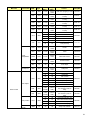
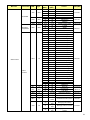
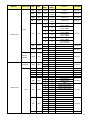
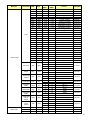
1
VTE-8400 Super-slim LED Display Model VTE-8400 Installation/Operation Manual COPYRIGHT AND TRADEMARKS: © Copyright 2015. This document contains proprietary information protected by copyright, trademark and other intellectual property laws. All rights are reserved. No part of this manual may be reproduced by any mechanical, electronic or other means, in any form, without our prior written permission. The trademarks reproduced in this document and used on the products are either owned or licensed by us, or by their respective holders. You may not reproduce or use the trademarks without our prior written consent. 2 Important Safety Instructions Thank you for your purchase of this VIVIDtouch Interactive Display. To ensure the best possible viewer experience, please read this manual carefully as it is your guide through the menus and operation. 1. Read these instructions. 2. Keep these instructions. 3. Heed all warnings. 4. Follow all instructions. 5. Do not use this apparatus near water. 6. Clean only with a dry cloth. 7. Do not block any of the ventilation openings. Install in accordance with the manufacturer’s instructions. 8. Do not install near any heat sources such as radiators, stoves, or other apparatus (including amplifiers) that produce heat. 9. Do not defeat the safety purpose of the polarised or grounding type plug. A polarised plug has two blades with one wider than the other. A grounding type plug has two blades and a third grounding prong. The wide blade or the third prong is provided for your safety. When the provided plug does not fit into your outlet, consult an electrician for the replacement of the obsolete outlet. 10. Protect the power cord from being walked on or pinched particularly at plugs, convenience receptacles and the point where they exit from the apparatus. 11. If an extension cord must be used, ensure that the voltage rating exceeds the maximum power consumption of the apparatus; otherwise, the extension cord may overheat. 12. Only use the attachments/ accessories specified by the manufacturer. 13. Use only with a cart, stand, bracket specified by the manufacturer or sold with the apparatus. When a cart is used, use caution when moving the cart/ apparatus to avoid injury from tip-over. 14. Disconnect all cables form the apparatus before moving it. 15. Unplug this apparatus during lightning storms or when unused for long periods of time. 16. Refer all servicing to qualified service personnel. Servicing is required when the apparatus has been damaged in any way, such as power supply cord or plug is damaged, liquid has been spilled or objects have fallen into the apparatus, the apparatus has been exposed to rain or moisture, does not operate normally, or has been dropped. 17. Keep the packing material in case the equipment should ever need to be shipped. 3 Compliance Information DECLARATION OF CONFORMITY: VIVIDtouch hereby declares that the Product's Model Number: VTE-8400 Conforms with the provisions of: • FCC: FCC CFR Title 47 Part 15 Subpart B Class A, CISPR 22:2008 • ICES-003 Issue 5: 2012 Class A (For Canada ) • CE: EN 55022: 2010 + AC: 2011 • EN 55024: 2010 • EN 61000-3-2: 2006 + A2: 2009 • EN 61000-3-3: 2008 • cTUVus: UL 60950-1:2007 • CB: IEC 60950-1: 2005 + A1 FCC PART 15: This equipment has been tested and found to comply with the limits for a Class A digital device, pursuant to part 15 of the FCC Rules. These limits are designed to provide reasonable protection against harmful interference when the equipment is operated in a commercial environment. This equipment generates, uses, and can radiate radio frequency energy and, if not installed and used in accordance with the instruction manual, may cause harmful interference to radio communications. Operation of this equipment in a residential area is likely to cause harmful interference in which case the user will be required to correct the interference at his own expense. 4 INDUSTRY CANADA (ICES-003): CAN ICES-3 (A)/NMB-3(A) PRODUCT DISPOSAL: The Product contains small amounts of tin, lead and / or mercury. Disposal of these materials maybe regulated due to environmental considerations. DISPOSAL OF OLD ELECTRICAL AND ELECTRONIC EQUIPMENT (Applicable throughout the European Union and other European countries with separate collection programs) This symbol found on your product or on its packaging, indicates that this product should not be treated as household waste when you wish to dispose of it. Instead, it should be handed over to an applicable collection point for the recycling of electric al and electronic equipment. By ensuring this product is disposed of correctly, you will help prevent potential negative consequences to the environment and human health, which could otherwise be caused by inappropriate disposal of this product. The recycling of materials will help to conserve natural resources. This symbol is only valid in the European Union. If you wish to discard this product, please contact your local authorities or dealer and ask for the correct method of disposal. 5 Notes 6 Table of Contents Important Safety Instructions ..................................................................................................................................... 3 Compliance Inform ation ............................................................................................................................................... 4 T able of Contents ............................................................................................................................................................. 7 List of Figures ................................................................................................................................................................... 9 1. Introduction ............................................................................................................................................................... 11 About This Manual ....................................................................................................................................................................... 11 Target Audience ..........................................................................................................................................................................................11 Textual and Graphic Conventions ......................................................................................................................................................11 Using This Manual ......................................................................................................................................................................... 12 Description, Features and Benefits ......................................................................................................................................... 13 Key Features and Benefits .......................................................................................................................................................................13 Touch Capability: .........................................................................................................................................................................................13 Parts List.............................................................................................................................................................................................................13 2. Controls and Functions ........................................................................................................................................... 15 Display at a Glance ..................................................................................................................................................................... 15 Input Panel .................................................................................................................................................................................... 17 Remote Control Unit ................................................................................................................................................................... 19 3. Installation ................................................................................................................................................................. 21 Remote Control ............................................................................................................................................................................ 21 Notes on Batteries .......................................................................................................................................................................................21 Notes on Remote Control Operation .....................................................................................................................................................21 Locking and Unlocking the Remote Control & Keypad on Display ...........................................................................................21 Quick Setup ..................................................................................................................................................................................... 22 Installation Considerations ..................................................................................................................................................... 22 Ambient Light ................................................................................................................................................................................................22 Ambient Heat ...............................................................................................................................................................................................22 Ventilation ......................................................................................................................................................................................................23 Mounting the Display .................................................................................................................................................................. 24 Connections to the Display ........................................................................................................................................................ 24 Connecting a Control System or PC:......................................................................................................................................................25 IR Extender Connection: ...........................................................................................................................................................................27 Connecting Source Components to the Display ..................................................................................................................................28 Turning on the Power .................................................................................................................................................................. 30 Changing the OSD Language..................................................................................................................................................... 31 Enabling the Touch Screen ...................................................................................................................................................... 31 Connecting the Touch Screen Controller Host Computer to the Display ..................................................................................31 Software Installation ..................................................................................................................................................................................32 Touch Screen Configuration Instructions .........................................................................................................................................33 4. Operation..................................................................................................................................................................... 36 Using the On-Screen Menus ..................................................................................................................................................... 36 Input Menu......................................................................................................................................................................................................38 Picture Menu..................................................................................................................................................................................................39 Audio Menu ....................................................................................................................................................................................................41 OSD Settings Menu ......................................................................................................................................................................................42 Setup Menu ......................................................................................................................................................................................................43 7 Advanced Setup Menu ....................................................................................................................................................................................44 Communication Menu ................................................................................................................................................................................46 Information ....................................................................................................................................................................................................47 5. Maintenance and Troubleshooting .................................................................................................................... 48 Maintenance .................................................................................................................................................................................. 48 Troubleshooting .......................................................................................................................................................................... 48 6. External Control ....................................................................................................................................................... 50 Serial Communications ............................................................................................................................................................ 50 RS-232 Connection and Port Configuration ...................................................................................................................................50 Command and Response Format ........................................................................................................................................................50 Command and Response Examples ....................................................................................................................................................51 Serial Command List ...................................................................................................................................................................................51 Using Discrete IR Codes .............................................................................................................................................................. 57 IR Command Protocol ...............................................................................................................................................................................57 IR Control Code List ....................................................................................................................................................................................58 7. Specifications ............................................................................................................................................................. 60 Supported Timings ........................................................................................................................................................................ 61 Overall Dimensions ..................................................................................................................................................................... 62 Appendix I: Moving and Carrying Notice .............................................................................................................. 64 Moving the Display: .................................................................................................................................................................... 64 Carrying the display: .................................................................................................................................................................. 64 Appendix II: Installing a Wall Mount ...................................................................................................................... 65 Appendix III: Installing a Pen Tray ......................................................................................................................... 66 Appendix IV: Wall Mount Safety Notes .................................................................................................................. 67 8 List of Figures FIGURE 2-1. DISPLAY REAR/SIDE VIEW .......................................................................................................................................................................................... 15 FIGURE 2-2. DISPLAY INPUT P ANEL S IDE V IEW .......................................................................................................................................................................... 17 FIGURE 2-3. DISPLAY R EMOTE CONTROL UNIT ............................................................................................................................................................................. 19 FIGURE 3-1. VENTILATION REQUIREMENTS FOR ENCLOSURE MOUNTING ................................................................................................................................ 23 FIGURE 3-2. RS-232 CONTROL SYSTEM CONNECTION ................................................................................................................................................................. 25 FIGURE 3-3. ETHERNET CONNECTION .............................................................................................................................................................................................. 26 FIGURE 3-4. IR EXTENDER CONNECTION ........................................................................................................................................................................................ 27 FIGURE 3-5. RECOMMENDED IR EXTENDER POSITION ................................................................................................................................................................ 27 FIGURE 4-1. OSD MENU STRUCTURE .............................................................................................................................................................................................. 37 FIGURE 7-1. VTE-8400 DISPLAY DIMENSIONS ............................................................................................................................................................................. 62 9 Notes 10 1. Introduction About This Manual This Owner’s Manual describes how to install, set up and operate the VIVIDtouch Series LED Display. Throughout this manual, the VIVIDtouch Series LED Display is referred to as the “display” Target Audience The manufacturer has prepared this manual to help installers and end users get the most out of the display. The manufacturer has made every effort to ensure that this manual is accurate as of the date it was printed. However, because of ongoing product improvements and customer feedback, it may require updating from time to time. Textual and Graphic Conventions Text Conventions: The following conventions are used in this manual, in order to clarify the information and instructions provided: • Remote and built-in keypad button identifiers are set in upper-case bold type; for example, “Press EXIT to return to the previous menu.” • Computer input ( commands you type) and output (responses that appear on-scree n) is shown in monospace (fixedwidth) type; for example: “To change the aspect ratio to Letterbox, type 07 00 02 41 53 50 03 08 <Enter>.” • All keys with functional names are initial-capped, set in bold type and enclosed in angle brackets. These keys are the following: <Enter>, <Spacebar>, <Control>, <Esc> and <Tab>. <Enter> indicates that you may press either the RETURN or ENTER key on your keyboard if it has both keys. • In addition to these conventions, underlining, boldface and / or italics are occasionally used to highlight important information, as in this example: NOTE A carriage return must be used after each command or string. 11 Graphic Conventions: These symbols appear in numerous places throughout the manual, to emphasise points that you must keep in mind to avoid problems with your equipment or injury: TIPS highlight time saving short cuts and helpful guidelines for using certain features. TIP NOTES emphasise text with unusual importance or special significance. They also provide supplemental information. NOTE CAUTION CAUTIONS alert users that a given action or omitted action can degrade performance or cause a malfunction. WARNING WARNINGS appear when a given action or omitted action can result in damage to the equipment, or possible non-fatal injury to the user. DANGER! DANGER appears when a given action can cause severe injury or death. Using This Manual Use the following table to locate the specific information you need in this manual. If you need... ... Turn to page: General information about the VIVIDtouch Series LED Display 13 Installation instructions 21 First-time configuration instructions 31 Advanced configuration instructions 44 Troubleshooting tips 48 Product specifications 60 12 Description, Features and Benefits The VIVIDtouch Series LED Display represents the cutting edge of direct-view LCD technology. They combine ultra-high resolution and unparalleled image quality with configurable I/O in a large-format display for a wide range of digital signage and control-room applications. Key Features and Benefits The display offers these key features and benefits: • Up to 3840 x 2160 @ 60 Hz resolution (16:9 Native Aspect Ratio) • Ultra-wide 178-degree Viewing Angle • (4) HDMI v1.4 inputs and DisplayPort 1.2 input with High-bandwidth Digital Content Protection (HDCP), VGA, RS232, (2) Touch USB and LAN connection • Displays up to 4 video sources simultaneously • Edge LED backlight with active ambient light sensor to adjust backlight automatically • Full range internal speakers • Signal source auto detection • Landscape support • Selectable OSD keypad lock Touch Capability: • Precise, highly-responsive touch technology • High touch sensitivity – no pressure required • Any touch: finger, gloved hand or pointer • Calibrated easily by software tools as attached • Windows 7/8, MAC and Linux compliant • One USB cable for easy Plug-and-Play operation Parts List Your display is shipped with the following items. If any items are missing or damaged, please contact your dealer or Customer Service. • VIVIDtouch Series LED Display • Remote Control Unit and batteries • AC Power Cord • Touch Stylus • Pen Tray • IR Extender Cable • USB Cable 13 • VGA Cable • HDMI Cable • Quick Start Guide • USB Key – Multi-Touch Drivers & User Manual 14 Notes 15 2. Controls and Functions Display at a Glance MENU/ SOUR Figure 2-1 shows the key display components, and the paragraphs that follow describe them. Figure 2-1. Display Rear/Side View 1. MAIN POWER SWITCH Connects or disconnects the display panel from the AC power source. 2. HANDLE Always use the handles when carrying the display. DO NOT touch or hold the screen face. 3. STATUS LED • Solid orange: display in standby mode • Blinking orange: display on, no input detected • Off: main power switch off • Solid green: display on, input detected 15 4. KEYPAD You can use the keypad instead of the remote control unit to operate the on-screen display (OSD) controls. The keypad operates as follows: On/Standby ( ) Press once to toggle from standby mode to on mode. Press it again to return to standby mode. SOURCE To select a source, press the SOURCE button repeatedly (with no menus visible on-screen). When a menu is visible on-screen, this button operates identically to the right-arrow (or ENTER) button on the display remote control unit. When a menu is visible on-screen, this button operates identically to the left-arrow button on display remote control unit. the / When a menu is visible on-screen, these buttons operate identically to the up-and down-arrow buttons on the display remote control unit. MENU/ EXIT Press this button to access the on-screen display (OSD) controls, or to exit the current menu and return to the previous one. 16 Input Panel Figure 2-2 shows the display input panel. Figure 2-2. Display Input Panel Side View 17 1. RS232C In A female, 9-pin D-sub connector for interfacing with a PC or control system. 2. LAN Port An RJ-45 connector for interfacing with a PC or home theater automation/control system via a Cat 5 cable. 3. Touch USB 1, 2 Touch USB 1: A standard, Type B USB port for connecting the HDMI and VGA input sources to the display. Touch USB 2: A standard, Type B USB port for connecting the DisplayPort input sources to the display. 4. HDMI 1, 2, 3, 4 HDCP-compliant digital video inputs for connecting HDMI sources. 5. DisplayPort DisplayPort 1.1a and DisplayPort-HDCP 1.1 compliant, SD/HD input for connecting SDTV, EDTV or HDTV component video sources. 6. VGA In (15-pin D-Sub) Connects components that have RGB or component output jacks, such as a personal computer or external DTV decoder (a break-out cable is needed for BNC-type connection). 7. PC Audio In Connects the audio output from a personal computer here. 8. IR Extender Connects the IR Extender cable provided with the display to this input. 9. Audio Out Connects external, powered speakers or an external audio receiver/ amplifier. 10. SPDIF Out Connects external, powered digital speakers or audio receiver/amplifier. 18 Remote Control Unit Figure 2-3 shows the display remote control, and Table 2-1 describes its functionality. Figure 2-3. Display Remote Control Unit 19 Table 2-1. Remote Control Button Descriptions Label 1 INFO 2 Provides source and resolution information Turns the monitor on and off VGA 3 Description DP Selects the PC RGB source Selects the DisplayPort source HDMI 1, 2, 3, 4 Selects the HDMI source P-POSITION Selects the PIP position PIP P-SOURCE Turns the PIP feature on and off Selects the secondary sub-source Selects the low light setting 4 Selects standard setting Selects high brightness setting 5 BLANK Blanks the screen. Press any key to restore. 6 FREEZE Freezes the screen. Press again to restore. Opens the monitor’s on-screen menu system. 7 MENU When the menu system is already open, pressing this button will select the previous submenu Navigates through submenus and settings 8 ENTER 9 EXIT SCALING Closes the menu system Selects each aspect ratio, in sequence: Full Screen, Native, Letter Box and Pillar Box SWAP Swaps the main and PIP source MUTE Turns off the sound BRIGHT 10 Selects highlighted menu choices CONTRAST AUTO Adjusts the brightness Adjusts the contrast Auto adjustment of VGA source SOURCE Selects each source, in sequence VOLUME - Decreases the sound volume VOLUME + Increases the sound volume 20 3. Installation NOTE Installation must be performed by a qualified custom video installation specialist. Remote Control To install batteries in the remote control: 1. Press down the tab on the cover and pull the cover up. 2. Insert the included batteries. Ensure that the polarities correctly match the component. 3. Insert the lower tab of the cover into the opening, and press down the cover until it clicks in place. and markings inside the battery Notes on Batteries Make sure that the battery polarities are correct when installing the batteries. • Do not mix an old battery with a new one or different types of batteries. • If you will not use the remote control for a long time, remove the batteries to avoid damage from battery leakage. • Do not expose batteries to excessive heat such as from sunshine, fire or the like. Notes on Remote Control Operation • Make sure that there is nothing obstructing the infrared beam between the remote control and the IR receiver on the display. • If the effective range of the remote control de creases, or it stops working, replace the batteries with new ones. • The remote control may fail to operate if the infrared remote sensor is exposed to bright sunlight or fluorescent lighting. • Ambient conditions may possibly impede the operation of the remote control. If this happens, point the remote control at the display, and repeat the operation. Locking and Unlocking the Remote Control & Keypad on Display You can lock the remote control buttons to prevent unauthorised persons from changing settings on the display. To do this, press ENTER, ENTER, EXIT, EXIT, ENTER and EXIT, in sequence. To unlock a locked remote control unit, use the same sequence of button presses. 21 Quick Setup Table 3-1 gives a quick overview of the display installation process. The sections following this one provide detailed instructions. Table 3-1. Installation Overview Step Procedure For Details, Refer to page... 1 Mount the display(s) on a wall (optional) 24 2 Connect other external equipment to the display (optional): Automation/control system (RS-232, Ethernet) External IR repeater 25 27 3 Connect signal sources to the display 28 4 Apply power to the display 30 5 Change the OSD language (optional) 31 6 Perform touch screen-specific installation and configuration tasks (VIVIDtouch): Connect touch screen controller host computer to the display 31 7 Display calibration: adjust the following for each input: • Aspect ratio • Colour level • Brightness • Tint • Contrast • Input position • Colour temperature and white balance 33 Installation Considerations Proper installation of your display will ensure a satisfying viewing experience. Whether a display is installed temporarily or permanently, the following should be taken into account to ensure the best performance of the display. Ambient Light In general, minimise or eliminate light sources directed at the screen. Contrast ratio in your images will be noticeably reduced if light directly strikes the screen, such as when a shaft of light from a window or floodlight falls on the image. Images may then appear washed out and less vibrant. Direct sunlight may affect touch operation. Ambient Heat Keep the ambient temperature constant and below 35°C (95°F). Keep the display away from heating and / or air conditioning vents. 22 Ventilation If you are mounting the display in an enclosure, leave sufficient space on all sides between it and surrounding objects, as shown in Figure 3-1. This allows heat to disperse, maintaining the proper operating temperature. 50 mm (2") Wall 50 mm (2") 50 mm (2") 50 mm (2") Wall 50 mm (2") Figure 3-1. Ventilation Requirements for Enclosure Mounting 23 Mounting the Display You can mount the display on a wall. If you do decide to wall-mount the display, ensure that the wall-mount bracket is installed according to the instructions included with it. The wall must be capable of supporting a redundant weight factor three (3) times the weight of the display, or be reinforced. We recommend that this be done by a custom installation specialist. NOTE Use only the approved wall-mount kit designed for your display. Connections to the Display Proceed as follows to connect the display to your video sources, external controller(s) – if present – and AC power. When connecting your equipment: • Turn off all equipment before making any connections. • Use the correct signal cables for each source. • For best performance and to minimise cable clutter, use high-quality cables that are only as long as necessary to connect two devices. (Don't use a 7m cable when a 1.8m cable will suffice.) • Ensure that the cables are securely connected. Tighten the thumbscrews on connectors that have them. 24 Connecting a Control System or PC: RS232 Connection Use a straight-through RS-232 cable with a 9-pin male connector to connect a PC or control system (if present) to the RS232 port on the display; see Figure 3-2. For more information about using this connection, refer to External Control on page 39. Figure 3-2. RS-232 Control System Connection 25 Ethernet Connection Use a standard Ethernet cable with an RJ-45 male connector to connect a PC or control/automation system (if present) to the Ethernet port on the display. For more information about using this connection, refer to External Control on page 39. Figure 3-3. Ethernet Connection 26 IR Extender Connection: Connect the provided IR extender cable to the IR Extender input as shown in Figure 3-4. Figure 3-4. IR Extender Connection Recommended IR Extender Positions for Cascading 84” Displays In controlled testing, the IR range is approximately 1.5 metres directly on-axis, and about 1 metre at plus or minus 15 degrees off-axis using the IR extender. Best performance is obtained in either position P1 or position P2. Figure 3-5. Recommended IR Extender Position 27 Connecting Source Components to the Display Connect your video sources to the display as shown and described in the sections that follow. DisplayPort Source Connection: See Figure 3-6. Figure 3-6. DisplayPort Source Connection 28 HDMI Source Connections: See Figure 3-7. TIP NOTE Use the HDMI inputs whenever possible. This ensures the highest video quality because the signal is carried in the digital domain throughout the entire signal path, from source component output into the display. This display supports the VESA Display Data Channel (DDC) standard. This standard provides “Plug and Play” capability; the display and a VESA DDC-compatible computer communicate their setting requirements, allowing for quick and easy setup. In order for Plug and Play to work correctly, you must turn on the display before you turn on the connected computer. Figure 3-7. HDMI Source Connections 29 VGA Source Connection: Connect a personal computer or other RGB source to the VGA input as shown in Figure 3-8. NOTE Refer to Supported Timings on page 51 for a list of compatible input signals. Figure 3-8. VGA Source Connections Turning on the Power 1. Turn on your source components. 2. Plug the female end of the supplied power cord into the AC receptacle on the side of the display (AC 100V ~ 240V). See Figure 2-2. 3. Connect the other end to your AC power source. 4. Turn on the main power switch at the side of the display (see Figure 2-1). The power indicator lights orange to indicate that the display is in “standby” mode. 5. Press the power button ( the keypad. 6. After a brief warm-up period, the display will display an image. NOTE ) on the remote control to turn on the display or press the power button ( ) on If there's no input signal for a period of time, the display will automatically go into power saving (sleep) mode. 30 Changing the OSD Language The display OSD language is initially set to English, but can also display the menus in different languages. To change the OSD language: 1. Press MENU. 2. Select Basic Settings from the Main Menu. 3. Select OSD Language from the Basic Settings Menu. 4. Press or to select the desired language and press ENTER. The change takes effect immediately. Enabling the Touch Screen Before setting up your display to support touch screen capability, ensure that: • The touch screen controller host computer is turned off. • The display is turned on. • The video output from the computer is connected to a video input on the display. See Figure 3-6, Figure 3-7 or Figure 3-8. Connecting the Touch Screen Controller Host Computer to the Display Use the provided USB c able to connect the touch screen controller host computer to the USB input as shown in Figure 3-9. Figure 3-9. Touch Screen Controller (USB) Connection After (and only after) making this connection, turn on your host computer. 31 Software Installation 1. Double-click the installation file TouchWin-[x.x.x.xxxx].exe, located on USB key provided with the display. (You can also download the most recent version of the TouchWin software from http://www.timelink.cn/index.php?m=content&oneid=369&id=385) 2. Choose the desired setup language (English or Simplified Chinese), then click OK. 3. The TouchWin Setup Wizard appears. Click Next twice, then click Install. 4. Select Yes, restart the computer now and click Finish to restart your computer and complete the installation. 32 Touch Screen Configuration Instructions From the Windows Start menu, choose Timelink -> TouchWin. Touch module information Touch screen configuration settings Product Information: This area of the TouchWin configuration window contains a variety of information about the touch module: the product type, firmware version and operating status. Should you ever need to contact Technical Support, this information will help them answer your questions or resolve product performance issues. Settings: From this area of the TouchWin configuration window, you can change settings, calibrate the touch screen or reset the product to its factory-default state. The following paragraphs describe these settings in detail. When you are finished configuring the touch screen, click Done to save your changes or Cancel to discard them. • Mode: Choose one of the following, then click Done. • MultiTouch: This mode is available only in Windows operating systems that support multi-touch; the user can interact with the display using multiple fingers simultaneously and independently of each other. (Refer to Software Requirements (Multi-Touch Operation), above.) • Mouse: This mode simulates the mouse to process the touch points. Generally, this mode is single-touch. All of the operating systems listed in the previous section (refer to Installing TouchWin Software on page 56) support mouse mode. 33 Calibration: If touching the screen does not place the cursor in the desired position, you may be able to correct this by performing a touch screen engine calibration. To do this: a. Click Calibration. A red spot and eight white spots against a black background appear on the screen. b. Click the red spot by hand and follow the red spot moving to finish the nine-point touch calibration. Only click the nine points with a finger on the black screen when calibrating. c. When you complete the nine-point calibration, a confirmation window appears. Click Done to accept the calibration; click Cancel or do nothing (in which case the calibration window automatically disappears after five seconds) to cancel the calibration. 34 • Advanced Setting: Click Advanced Setting to display the Advanced Setting window. When you are finished, select Done to save your changes or Cancel to discard them. • Right Click Simulation: When this option is enabled, pressing on the screen (as opposed to tapping it) performs a “right-click” mouse button action. The amount of time the finger must remain on the touch screen to perform this action is configurable; refer to Right Click Duration, below. • TUIO (Tangible User Interface Object) Support: Certain applications require access to touch point messages via the TUIO protocol. Also, certain operating systems require TUIO to provide multi-touch capability (refer to Software Requirements (Single-Touch Operation) on page 20). Therefore, it is recommended that you enable this option. • Right Click Duration: When Right Click Simulation is enabled, this slider controls how long a finger press action must be in order for it to be interpreted as a “right-click” action. • Double Click Speed: This slider controls the maximum duration between two touches in order for them to be interpreted as a “double-click” action. • Right/Double Click Range: This slider controls the maximum distance between two touches in order for them to be interpreted as a “double-click” or “right-click” action. • Reset: To restore all TouchWin configuration settings to their factory defaults and undo the effects of any previous calibrations, click Reset. 35 4. Operation Using the On-Screen Menus To display the on-screen menus, press MENU on the remote control (Figure 2-3) or built-in keypad (Figure 2-1). To select a sub-menu, use the and To select a menu item, use the ENTER. buttons to highlight it. Then, press and to enter that sub-me nu. buttons to highlight it. Then, press or to adjust that setting and press The OSD menus are arranged hierarchically, as shown in Figure 4-1. Depending on the selected input source and signal characteristics, some menu options may not be available. Main Menu SubMenu Value Input Main Input VGA; DisplayPort; HDMI1; HDMI2; HDMI3; HDMI4; Auto Scan Off; Main; PxP; All PiP Mode Off; PiP; PbP; 3Window; 4Window Sub1 Input VGA; DisplayPort; HDMI1; HDMI2; HDMI3; HDMI4 Sub2 Input (same as above) Sub3 Input (same as above) PiP Size Small; Mid; Large PiP Position TopR; TopL; BotR; BotL Swap Picture Audio Picture Format Main: Full Screen/Letterbox/ 4:3/1:1; PxP: Full Screen/Letterbox/ 4:3 Scheme User, Vivid, Cinema, Game, Sport Contrast 0, 1, 2, ...., 50, ....100 Brightness 0, 1, 2, ...., 50, ....100 Sharpness 0, 1, 2, ...., 50, ....100 Hue 0, 1, 2, ...., 50, ....100 Saturation 0, 1, 2, ...., 50, ....100 Backlight 0, 1, 2, ...., 50, ...., 80, ....100 Colour Temp & Gamma 5000K; 6500K; 7500K; 9300K; User; off; 2.2 HDMI RGB Range Auto; Full; Limited Volume 0~100 Treble -6~6 Bass -6~6 Balance -6~6 Internal Speaker On; Off Audio Source Line-In ; DisplayPort ; HDMI1 ; HDMI2 ; HDMI3 ; HDMI4 ; 36 Main Menu OSD Settings Setup Adv. Setup Communication Information NOTE SubMenu Horizontal Vertical Transparency OSD Timeout Language Splash Screen Auto Adjustment H.Position V.Position Phase Clock Zoom Power LED Real Time Clock Smart Light Control IRFM Noise Reduction Wake Up From Sleep DP Ver. EDID Setup Touch Control Factory Reset RS232 Baud Rate Enable Network IP Address Settings Power Status Alert Source Status Alert Signal Lost Alert Load Default Device MAC (Timing info) Firmware Version SubMCU Version Serial Number Value 0~100 0~100 Off; 1~4 5s; 10s; 20s; 30s; 60s English, German, Chinese On; Off 0~100 0~100 0~100 0~100 10 steps On; Off User Mode; Workday Mode; Everyday Mode Off; DCR; Light Sensor On; Off Off; Low; Medium; High VGA Only; Digital, RS232. Ethernet; Never Sleep 1.1; 1.2 HDMI: 4K2K/1080P; DP: 4K2K/1080P Auto; External Yes; No 115200; 38400; 19200; 9600 Yes; No Please refer to Section 5.1 detail settings. Yes; No Yes; No Yes; No Yes; No Shows the MAC address of the device Shows the name of input source Shows the firmware version of the monitor Shows the firmware version of the monitor Shows the Serial Number of the monitor Default settings appear in bold type. Figure 4-1. OSD Menu Structure 37 Input Menu This menu is used for selecting the main input source (Main) and up to three Picture-in-Picture input sources (Sub1, Sub2 and Sub3). Up to four sources can be displayed at the same time. Main Input Select the main input source Options: DisplayPort, HDMI1, HDMI2, HDMI3, HDMI4, VGA Auto Scan Select whether the display will automatically scan for a main input source Options: Off, Main, PxP, All PiP Mode Select the PiP (Picture-in-Picture) mode Options: Off, PiP, PbP, 3Window, 4Window Sub1 Input Select the source for the primary PiP window Options: DisplayPort, HDMI1, HDMI2, HDMI3, HDMI4, VGA Note: This function is only available when PiP Mode is set to PiP, PbP, 3Window or 4Window Sub2 Input Select the source for the secondary PiP window Options: DisplayPort, HDMI1, HDMI2, HDMI3, HDMI4, VGA Note: This function is only available when PiP Mode is set to 3Window or 4Window Sub3 Input Select the source for the tertiary PiP window Options: DisplayPort, HDMI1, HDMI2, HDMI3, HDMI4, VGA Note: This function is only available when PiP Mode is set to 4Window PIP Size Select the size of the primary PiP window Options: Small, Mid, Large Note: This function is only available when PiP Mode is set to PiP PIP Position Set the position of the primary PiP window Options: TopR, TopL, BotR, BotL Note: This function is only available when PiP Mode is set to PiP Swap Swap the main input source with the primary PiP source Note: This function is only available when PiP Mode is set to PiP, PbP, 3Window or 4Window 38 Picture Menu This menu is used for making common image adjustments. Picture Format Adjust the picture format of the screen Options: Full Screen, Letterbox, 4:3, 1:1; Default: Full Screen Scheme Press or to select one of the following: Options: User, Vivid, Cinema, Game, Sport; Default: User Contrast Increase or decrease the contrast of picture. Press or to select the desired level, and then press ENTER. Range: 0~100; Default: 50 Brightness Increase or decrease the brightness of picture. Press or to select the desired level, and then press ENTER. Range: 0~100; Default: 50 Sharpness Adjust the definition of picture. Press or to select the desired level, and then press ENTER. Range: 0~100; Default: 50 Hue Increase or decrease the green hue. Press or to select the desired level, and then press ENTER. Range: 0~100; Default: 50 Note: This function is not available when displaying PC or graphics sources Saturation Adjust the brilliance and brightness. Press or to select the desired level, and then press ENTER. Range: 0~100; Default: 50 Note: This function is not available when displaying PC or graphics sources Backlight Increase or decrease the intensity of the LCD backlight. Press or to select the desired level, and then press ENTER. Range: 0~100; Default: 80 Gamma Select gamma curve Options: Off, 2.2; Default: 2.2 Colour Temp Select a colour temperature, or select User to make RGB adjustments. Options: User, 5000K, 6500K, 7500K and 9300K; Default: 9300K 39 HDMI RGB Range Select an RGB range for the HDMI input. Options: Auto, Full, Limited; Default: Auto Colour Temperature Settings Red Gain Set Colour Temperature to “User Mode” in order to adjust this setting. Range: 0~100 Default: 100 Green Gain Set Colour Temperature to “User Mode” in order to adjust this setting. Range: 0~100 Default: 100 Blue Gain Set Colour Temperature to “User Mode” in order to adjust this setting. Range: 0~100 Default: 100 Red Offset Set Colour Temperature to “User Mode” in order to adjust this setting. Range: 0~100 Default: 50 Green Offset Set Colour Temperature to “User Mode” in order to adjust this setting. Range: 0~100 Default: 50 Blue Offset Set Colour Temperature to “User Mode” in order to adjust this setting. Range: 0~100 Default: 50 40 Audio Menu This menu is used for adjusting volume settings. Volume Adjust the sound. Press or to select the desired level, and then press ENTER. Range: 0~100 Default: 50 Treble Adjust the sound in high tones (treble). Press or to select the desired level, and then press ENTER. Range: -6~6 Default: 0 Bass Adjust the sound in low tones (bass). Press or to select the desired level, and then press ENTER. Range: -6~6 Default: 0 Balance Adjust the balance of the left and right speakers. Press or to select the desired level, and then press ENTER. Range: -6~6 Default: 0 Internal Speaker Turn the internal speaker on or off Default: On Audio Source Select the audio source for the Main input Options: DisplayPort, HDMI1, HDMI2, HDMI3, HDMI4, Line-In Default: Line-in 41 OSD Settings Menu This menu is used to make initial set-up adjustments to the OSD (On-Screen Display) menu and other on-screen messages. Horizontal Adjust the horizontal position of the OSD menu. Press or to select the desired level, and then press ENTER. Range: 0~100 Default: 50 Vertical Adjust the vertical position of the OSD menu. Press or to select the desired level, and then press ENTER. Range: 0~100 Default: 50 Transparency Adjust the transparency of the OSD menu. Press or to select the desired level, and then press ENTER. Range: Off, 1~4; Default: Off OSD Timeout Adjust the time in seconds before the OSD menu disappears. Press or to select the desired level, and then press ENTER. Options: 5s, 10s, 20s, 30s, 60s Default: 30s Language Select the OSD language Options: English, Slovenian, Croatian, Serbian, Hungarian, Macedonia, Bosnian Default: English Splash Screen Select whether a splash screen appears when the monitor is powered up Options: On, Off Default: On 42 Setup Menu Auto Adjustment Force the display to reacquire and lock to the input signal (VGA source only). This is useful when the signal quality is marginal. Note: This feature does not continually reacquire the signal. Options: No, Yes Default: No H. Position Adjust the horizontal position of the image (VGA source only). Press or to select the desired level, and then press ENTER. Range: 0~100 Default: 50 V. Position Adjust the vertical position of the image (VGA source only). Press or to select the desired level, and then press ENTER. Range: 0~100 Default: 50 Phase Adjust the phase of the displayed signal (VGA source only). Press or to select the desired level, and then press ENTER. Range: 0~100 Clock Adjust the clock of the displayed signal (VGA source only). Press or to select the desired level, and then press ENTER. Range: 0~100 Zoom Adjust the zoom (overscan) of the image. Press or to select the desired level, and then press ENTER. Range: 10 steps Power LED Enable or disable the status LED Options: On, Off Default: On Real Time Clock Set the internal clock of the display, and to power on and off the display at preset times if desired. Options: User mode, Workday mode, Everyday mode Default: User mode 43 Advanced Setup Menu Smart Light Control Enable dynamic contrast (DCR) or ambient light sensor Options: Off, DCR, Light Sensor Default: Off IRFM Create slight frame motion to help avoid image retention Options: On, Off Default: Off Noise Reduction Reduce random noise in the video content Options: Off, Low, Medium, High Default: Off Wake Up From Sleep Options: VGA Only, Digital, RS232, Ethernet; Never Sleep Default: VGA Only DP Ver. Select DisplayPort version of the DisplayPort inputs Options: 1.1, 1.2 Note: DisplayPort 1.2 is the more modern standard and supports 3840x2160 @ 60 Hz resolution. However, sometimes DisplayPort 1.1 is needed for compatibility with older graphics cards. EDID Setup Select EDID (Extended Display Identification Data) of the HDMI and DisplayPort inputs Options: 1080p, 4K2K Note: Use the 1080p setting for the broadest support of lower resolution sources. Use 4K2K setting to support high resolution sources such as 3840x2160. Touch Control Select one of the touch connections, or choose auto detection. Options: Auto, External Default: Auto Factory Reset Restore all settings to their default. Options: No, Yes Default: No 44 Wake Up from Sleep By default, the display will enter power saving (Sleep Mode) if no signal is received for 5 minutes. Normally, the RS-232, DisplayPort, and HDMI inputs are inactive in Sleep Mode, to save power. To change the behavior of Sleep Mode, change the “Wake up from Sleep” setting in the “Adv. Setup” menu. VGA Only (default) – The RS-232, DisplayPort, and HDMI inputs are inactive when the display is in sleep mode. The display will wake up when it receives a signal at the VGA input. Digital, RS232, Ethernet – The RS-232, DisplayPort and HDMI inputs stay active when the display is in sleep mode. The display will wake up when it receives a signal at either of the DisplayPort, HDMI, or RS-232 inputs, or via LAN connection. 45 Communication Menu This menu configures the display’s RS232 and Ethernet communication ports. Baud Rate Select the baud rate of the display’s RS232 port Options: 115200, 38400, 19200, 9600 Default: 115200 Enable Network Enable the display’s built-in Ethernet port Options: No, Yes Default: No IP Address Settings Enable Dynamic IP mode or set the static IP address of the display’s Ethernet port Power Status Alert Enable an automatic alert when the display is powered down Options: No, Yes Default: No Source Status Alert Enable an automatic alert when the source is changed Options: No, Yes Default: No Signal Lost Alert Enable an automatic alert when the video signal is lost Options: No, Yes Default: No Load Default Load default communication settings Options: No, Yes Default: No Device MAC Display the MAC address of the device 46 Network Settings To assign an IP address to your display, access the IP Address Settings Menu in the Communication Menu. Consult your system administrator if you do not know how to configure the parameters shown in the menu. The default settings are shown below. Item DHCP IP ADDRESS SUBNET MASK DEFAULT GATEWAY DNS Addr. Setting Disable 192.168.2.1 255.255.255.0 192.168.2.1 192.168.2.1 Information This read-only menu provides information on the active sources and the latest firmware version 47 5. Maintenance and Troubleshooting Maintenance The VIVIDtouch Series LED Displays does not require any routine maintenance other than occasional cleaning with a nonabrasive cloth. There are no user-serviceable or replaceable parts. Unless you are a qualified, factory-trained technician, do not attempt to repair or replace any system component yourself. You will void the product warranty if you do so. Troubleshooting Table 5-1 provides some general guidelines for troubleshooting problems you may encounter with the VIVIDtouch Series LED Display. If the suggested solutions fails to resolve the problem or if you encounter an issue not described here, please contact your dealer. Table 5-1. Troubleshooting Chart Symptom The display does not turn on. Possible Cause(s) • The display is not plugged in or the AC outlet is not active. • The main power switch is off. • The remote control batteries have run out. The display is on and menus appear, but there is no picture. The remote control does not work. Solution • Ensure that the display is plugged in and that the AC outlet is active. • Set the main power switch (see Figure 2-1) to the on position. • Replace the batteries. • Incorrect source selection. • Source component is not turned on. • Source component is connected incorrectly or not at all. • Select the correct source. • Turn on the source component. • The remote control batteries have run out. • The buttons are locked. • Replace the batteries. • IR extender is not connected. • Check connections from the source component to the display. • Unlock the buttons by pressing ENTER, ENTER, EXIT, EXIT, ENTER and EXIT, in sequence. • Verify that the IR extender cable is correctly connected (see Figure 3-3). Image geometry is incorrect. • Incorrect aspect ratio selection. • Select a different aspect ratio. The display is jittery or unstable. • Poor-quality or improperly connected source. • Ensure that the source is properly connected and of adequate quality for detection. • The horizontal or vertical scan frequency of the input sign al may be out of range for the display. • Correct at the source. • Contrast is set too high. • Decrease the contrast setting. Image is too bright and / or lacks definition in the bright areas of the im age. 48 Table 5-1. Troubleshooting Chart (continued) Symptom Possible Cause(s) Solution Image appears “ washed out ” and / or dark areas app ear too bright. • Brightness is set too high. • Decrease the brightness setting. Image is too dark. • Brightness and / or Backlight are set too low. • Increase the brightness and / or backlight settings. Images from an HDMI source do not display. • The resolution and frequency of the video card in the computer are not compatible with the display. • HDMI c ab le from source to display is either defective or too long. • Select a compatible resolution and vertical frequency (refer to Supported Timings on page 61). • The resolution and frequency of the video card in the computer are not compatible with the display. • Clock and Phase settings nee d adjustment. • Select a compatible resolution and vertical frequency (refer to Supported Timings on page 61). • Multi-touch controller host computer is not connected correctly. • Host computer hardware or OS incompatibility. • See Figure 3-7. Computer images do not display correctly. Touch screen doesn’t work. • Try a known-good and / or shorter HDMI c able. • Adjust Clocks and Phase settings (refer to Phase - VGA sources on page 45 and Clock - VGA sources on page 45). • Refer to Enabling the Touch Screen on page 31. Should you require assistance with a suspected hardware fault, please contact the support line below. You will require your unit serial number. The operator will attempt to diagnose any fault and will take action as appropriate. UK Warranty Support Tel. 08450 724 999 Email. [email protected] 49 6. External Control In addition to using the display keypad or remote control unit, you can control the display using a serial (RS-232) link to send ASCII commands and receive responses to those commands. You also use discrete infrared (IR) control codes to program a third-party remote control unit. For more information, refer to Using Discrete IR Codes on page 46. Serial Communications The display uses a simple text-based control protocol to take requests from control devices and to provide responses to such devices. This section describes how to send control messages over a serial link between the display and an automation/control system or a PC running a terminal emulation program such as Windows® HyperTerminal or Tera Term. RS-232 Connection and Port Configuration Connect your control system or PC to the RS-232 input of the display as shown in Figure 3-2. Configure the RS-232 controller or PC serial port as follows: no parity, 8 data bits, 1 stop bit and no flow control. Set the baud rate to 115200, to match that of the display RS-232 port. Command and Response Format Commands sent from an automation/control system or PC to the display must have the following format: [STX] [IDT] [TYPE] [CMD] ([VALUE] or [REPLY]) [ETX] [CR] Where: • [STX] indicates the start of the command data (always 07). • [IDT] is the display ID (always 01). • [TYPE] is the command type: 00 = return to host (response from the LCD panel) = read / action = write • [VALUE] is the parameter setting for the command. • [REPLY] is the parameter setting for the command, acknowledged by the display in its response to a command. • [ETX] indicates the end of the command data (always 08). • [CR] is the ASCII carriage return key (0x0D). 50 Command and Response Examples Here are some examples of serial commands and their responses: Table 6-1. Serial Command/ Response Examples Description Command Sent to LCD Panel Response Received from LCD Panel Turn LCD panel power off. 07 01 02 50 4F 57 00 08 07 01 00 50 4F 57 00 08 Turn LCD panel power on. 07 01 02 50 4F 57 01 08 07 01 00 50 4F 57 01 08 Request LCD panel power status. 07 01 01 50 4F 57 08 07 01 00 50 4F 57 XX 08 (XX = 0 when off or 1 when on) Set the LCD panel contrast to 30 (1E hex). 07 01 02 43 4F 4E 1E 08 07 01 00 43 4F 4E 1E 08 Reset the LCD panel display settings. 07 01 02 41 4C 4C 00 08 07 01 00 41 4C 4C 00 08 Request LCD panel serial number. 07 01 01 53 45 52 08 07 01 00 53 45 52 S(0)…S(12) 08 S(0) …S(12) = the serial number in ASCII Request LCD panel firmware version. 07 01 01 47 56 45 08 07 01 00 47 56 45 S(0)…S(5) 08 S(0) …S(5) = the firmware version in ASCII Serial Command List Tab le 6-2 lists all supported commands. Table 6-2. Serial Commands Main Item Power Control and Input Source Display Adjustment Control Item CMD Type Value (DEC) 00 01 00 09 10 11 12 13 Power Control POW W/R Input Source MIN W/R BRI W/R 0~100 BRL W/R 0~100 BLC W/R 00 01 CON W/R 0~100 HUE W/R 0~100 SAT W/R 0~100 W/R 00 01 02 03 Display Adjustment NOR Reply (DEC) 00 01 00 09 10 11 12 13 Current value Current value 00 01 Current value Current value Current value 00 01 02 03 Content Off (soft power) On (soft power) VGA HDMI 1 HDMI 2 HDMI 3 HDMI 4 Displayport CMD (HEX) 50 4F 57 4D 49 4E Back Light Brightness 42 52 49 Digital Brightness Level 42 52 4C Off (Back Light) On (Back Light) 42 4C 43 Contrast 43 4F 4E Hue 48 55 45 Saturation 53 41 54 Noise Reduction: Off Noise Reduction: Low Noise Reduction: Medium Noise Reduction: High 4E 4F 52 51 Main Item Control Item VGA Adjustment Sharpness PIP/Main Swap 01 01 2.20 (Gamma) USR W/R 0~100 USG W/R 0~100 USB W/R 0~100 UOR W/R 0~100 UOG W/R 0~100 UOB W/R 0~100 Content Red Gain (mapping 0~100) Green Gain (mapping 0~100) Blue Gain (mapping 0~100) Red Offset (mapping 0~100) Green Offset (mapping 0~100) Blue Offset (mapping 0~100) User 6500K 9300K 7500K Off (Gamma) CMD (HEX) 55 53 52 55 53 47 55 53 42 55 4F 52 55 4F 47 55 4F 42 COT W/R GAC W/R PHA W/R 0~100 Current value Phase 50 48 41 CLO W/R 0~100 Current value Clock 43 4C 4F HOR R/W 0~100 Current value Horizontal Position 48 4F 52 VER R/W 0~100 Current value Vertical Position 56 45 52 ADJ W 00 00 Auto Adjust 41 44 4A SHA W/R 0~100 Current value Sharpness 53 48 41 00 00 PIP OFF 01 01 PIP Small 02 02 PIP medium 03 03 PIP large 04 04 PbP (Side By Side) 06 06 3 Windows 07 07 W/R PIP Adjust PIP position 00 01 02 07 00 Reply (DEC) Current value Current value Current value Current value Current value Current value 00 01 02 07 00 Type PSC Other Control Value (DEC) CMD PIO W/R (refer to PIN) (refer to PIN) PIP W/R (refer to PIN) (refer to PIN) 00 00 4 Windows Select the input source of sub window 2 (refer to PIN) Select the input source of sub window 3 (refer to PIN) PIP Position Bottom-left 01 01 PIP Position Bottom-Right 02 02 PIP Position Top-left 03 03 PIP Position Top-right 00 00 Swap main and PIP PPO SWA W/R W 43 4F 54 47 41 43 50 53 43 50 49 4F 50 49 50 50 50 4F 53 57 41 52 Main Item Control Item CMD Type ASP W/R PAS W/R ZOM W/R BRA W/R RCU W ALL W KLC W/R SER MNA GVE R R R RTV R SCALING Baudrate Adjustment Other Control Other Control Value (DEC) 00 01 02 03 01 02 03 0~10 00 01 02 03 00 01 02 03 04 05 06 07 08 10 11 12 18 19 20 21 22 23 24 25 26 27 28 29 30 31 32 00 00 01 00 GVS W 01 02 Reply (DEC) 00 01 02 03 01 02 03 0~10 00 01 02 03 00 01 02 03 04 05 06 07 08 10 11 12 18 19 20 21 22 23 24 25 26 27 28 29 30 31 32 00 00 01 13 bytes 13 bytes 6 bytes Current value [00]+5 byte [01]+3 byte [02]+5 byte Content Native Full Screen Pillarbox/4:3 Letterbox Full Screen Pillarbox/4:3 Letterbox Adjust overscan ratio 115200 38400 19200 9600 MENU Key INFO Key UP Key DOWN Key LEFT Key RIGHT Key ENTER Key EXIT Key VGA Key HDMI1 Key HDMI2 Key DISPLAYPORT Key SOURCE Key P-SOURCE Key PIP Key P-POSITION Key SWAP Key SCALING Key FREEZE Key MUTE Key BRIGHT Key CONTRAST Key AUTO Key VOLUME+ Key VOLUME- Key HDMI3 Key HDMI4 Key Reset all Un-lock keys Lock keys Read Serial Number Read Model Name Read Firmware Version Read RS232 table Version CMD (HEX) 41 53 50 50 41 53 5A 4F 4D 42 52 41 52 43 55 41 4C 4C 4B 4C 43 53 45 52 4D 4E 41 47 56 45 52 54 56 Querying main version Querying sub mcu version 47 56 53 Querying network module version 53 Main Item Control Item Value (DEC) CMD Type VOL W/R 0~100 BAS W/R 0~12 TRE W/R 0~12 BAL W/R 0~12 Reply (DEC) Current value Current value Current value Current value 00 00 01 01 02 02 03 03 04 04 05 05 00 01 00 01 00 01 02 03 04 0 1 2 0~99 1~12 1~31 0~23 0~59 0 1 2 1 2 4 8 16 32 64 1 2 4 8 16 32 64 0~23 00 01 00 01 00 01 02 03 04 0 1 2 0~99 1~12 1~31 0~23 0~59 0 1 2 1 2 4 8 16 32 64 1 2 4 8 16 32 64 0~23 Audio CAS W/R Other Control INS W/R MUT W/R Scheme selection SCM W/R EcoMode WFS W/R RTY RTM RTD RTH RTN W/R W/R W/R W/R W/R TMS W/R AEN W/R AEF W/R NNH W/R Other Control RTC Content CMD (HEX) volume 56 4F 4C Bass(-6~6) 42 41 53 Treble(-6~6) 54 52 45 Bass(-6~6) 42 41 4C Current audio source :Analog Current audio source :HDMI1 Current audio source :HDMI2 Current audio source :HDMI3 Current audio source :HDMI4 Current audio source :Displayport Internal Speaker Off Internal Speaker On Mute Off Mute On User Sport Game Cinema Vivid Set VGA_ONLY Set VGA_DIGITAL_RS232 Set Never_Sleep Set Real time Year Set Real time Month Set Real time Day Set Real time Hour Set Real time Minute Everyday Mode Workday Mode User Sunday Alarm Enable Monday Alarm Enable Tuesday Alarm Enable Wednesday Alarm Enable Thursday Alarm Enable Friday Alarm Enable Saturday Alarm Enable Sunday Alarm Disable Monday Alarm Disable Tuesday Alarm Disable Wednesday Alarm Disable Thursday Alarm Disable Friday Alarm Disable Saturday Alarm Disable Monday On Hour 43 41 53 49 4E 53 4D 55 54 53 43 4D 57 46 53 52 54 59 52 54 4D 52 54 44 52 54 48 52 54 4E 54 4D 53 41 45 4E 41 45 46 4E 4E 48 54 Main Item Control Item CMD Type RTC NNM NFH NFM ENH ENM EFH EFM DNH DNM DFH DFM UNH UNM UFH UFM INH INM IFH IFM TNH TNM TFH TFM SNH SNM SFH SFM W/R W/R W/R W/R W/R W/R W/R W/R W/R W/R W/R W/R W/R W/R W/R W/R W/R W/R W/R W/R W/R W/R W/R W/R W/R W/R W/R Auto Scan ATS W/R IRFM IRF W/R Smart Light Control SLC W/R Power LED LED W/R DisplayPort Mode DPM W/R HDMI EDID EDH W/R DisplayPort EDID EDP W/R HDMI RGB Colour Range HCR W/R Touch Control TOC W/R Transparency H Position V Position OST OSH OSV W/R W/R W/R Other Control OSD Control Value (DEC) 0~59 0~23 0~59 0~23 0~59 0~23 0~59 0~23 0~59 0~23 0~59 0~23 0~59 0~23 0~59 0~23 0~59 0~23 0~59 0~23 0~59 0~23 0~59 0~23 0~59 0~23 0~59 0 1 2 3 0 1 0 1 2 0 1 0 1 00 01 00 01 00 01 02 00 02 03 0~4 0~100 0~100 Reply (DEC) 0~59 0~23 0~59 0~23 0~59 0~23 0~59 0~23 0~59 0~23 0~59 0~23 0~59 0~23 0~59 0~23 0~59 0~23 0~59 0~23 0~59 0~23 0~59 0~23 0~59 0~23 0~59 0 1 2 3 0 1 0 1 2 0 1 0 1 00 01 00 01 00 01 02 00 02 03 0~4 0~100 0~100 Content Monday On Minute Monday Off Hour Monday Off Minute Tuesday On Hour Tuesday On Minute Tuesday Off Hour Tuesday Off Minute Wednesday On Hour Wednesday On Minute Wednesday Off Hour Wednesday Off Minute Thursday On Hour Thursday On Minute Thursday Off Hour Thursday Off Minute Friday On Hour Friday On Minute Friday Off Hour Friday Off Minute Saturday On Hour Saturday On Minute Saturday Off Hour Saturday Off Minute Sunday On Hour Sunday On Minute Sunday Off Hour Sunday Off Minute Off Main Multi All Off On Off DCR Light Sensor Off On DP 1.1 DP 1.2 4Kx2K 1080P 4Kx2K 1080P Auto Detect Full Range Limited Range Auto (Read Only) Touch USB1 Touch USB2 OSD Transparency OSD H Position OSD V Position CMD (HEX) 4E 4E 4D 4E 46 48 4E 46 4D 45 4E 48 45 4E 4D 45 46 48 45 46 4D 44 4E 48 44 4E 4D 44 46 48 44 46 4D 55 4E 48 55 4E 4D 55 46 48 55 46 4D 49 4E 48 49 4E 4D 49 46 48 49 46 4D 54 4E 48 54 4E 4D 54 46 48 54 46 4D 53 4E 48 53 4E 4D 53 46 48 53 46 4D 41 54 53 49 52 46 53 4C 43 4C 45 44 44 50 4D 45 44 48 45 44 50 48 43 52 54 4F 43 4F 53 54 4F 53 48 4F 53 56 55 Main Item OSD Control CMD Type Value (DEC) OSD Timeout OSO W/R 5~60 Splash Screen SPS W/R Network Enable NWE W/R Dynamic IP DIP W/R Default LDS W PSA W/R SSA W/R SLA W/R IP1 IP2 IP3 IP4 MK1 MK2 MK3 MK4 GW1 GW2 GW3 GW4 FD1 FD2 FD3 FD4 SNS W/R W/R W/R W/R W/R W/R W/R W/R W/R W/R W/R W/R W/R W/R W/R W/R W Control Item E-Mail Alert Ethernet Setup Static IP Settings 0 1 0 1 0 1 Reply (DEC) Current value 0 1 0 1 0 1 0 0 0 1 0 1 0 1 0~255 0~255 0~255 0~255 0~255 0~255 0~255 0~255 0~255 0~255 0~255 0~255 0~255 0~255 0~255 0~255 0 0 1 0 1 0 1 0~255 0~255 0~255 0~255 0~255 0~255 0~255 0~255 0~255 0~255 0~255 0~255 0~255 0~255 0~255 0~255 0 Content OSD Timeout (5, 10, 20, 30, 60 sec) Off On No Yes Disable Enable Load network default settings (It will take about 15 seconds.) Off (Power Status Alert) On (Power Status Alert) Off (Source Status Alert) On (Source Status Alert) Off (Signal Lost Alert) On (Signal Lost Alert) Static IP Address 1 Static IP Address 2 Static IP Address 3 Static IP Address 4 Subnet Mask 1 Subnet Mask 2 Subnet Mask 3 Subnet Mask 4 Gateway 1 Gateway 2 Gateway 3 Gateway 4 DNS Address 1 DNS Address 2 DNS Address 3 DNS Address 4 Save Network Settings CMD (HEX) 4F 53 4F 53 50 53 4E 57 45 44 49 50 4C 44 53 50 53 41 53 53 41 53 4C 41 49 50 31 49 50 32 49 50 33 49 50 34 4D 4B 31 4D 4B 32 4D 4B 33 4D 4B 34 47 57 31 47 57 32 47 57 33 47 57 34 46 44 31 46 44 32 46 44 33 46 44 34 53 4E 53 56 Using Discrete IR Codes The display accepts commands in the form of infrared (IR) signals that conform to the NEC protocol. Each display remote control button has an IR control code associated with it. You can use these codes to program a third-party, “universal” remote control unit to work with the display. These thirdparty products usually come with a computer software application for this purpose. For more information, consult the documentation provided with the remote control unit. IR Command Protocol The IR control codes have the following characteristics: • Each code consists of the following: A leader pulse (a modulated pulse of 9 ms followed by a non-modulated pulse of 4.5 ms); 16 address bits (also called a “custom code”): eight (8) bits for the address followed by the logical inverse of the address. The custom code for the display is 16559 decimal (0x40AF, binary 01000000 10101111). 16 da ta bits: eight (8) bits for the command followed by the logic al inverse of the command; and An end pulse (a modulated pulse of 0.56 ms, similar to the modulated pulse in the ‘0’ and ‘1’ bits). The end of the modulated pulse constitutes the end of the data transmission. • The carrier frequency is 38 kHz, with the modulated pulses having a 33% duty cycle. • Commands are sent at a maximum rate of 9 Hz. For example, here is the NEC control code for the POWER button on the display remote control unit: Hex Binary Function 40 01000000 Cust. Code Byte 1 AF 10101111 Cust. Code Byte 2 1C 00011100 Command E3 11100011 Command (Logical Inverse) 57 IR Control Code List Tab le 6-3 lists the IR control codes for the display. Table 6-3. Infrared (IR) Control Codes Customer Code Data Code Function 40AF 04FB INFO 40AF 1CE3 POWER 40AF 07F8 VGA 40AF 08F7 DISPLAYPORT 40AF 09F6 HDMI1 40AF 0AF5 HDMI2 40AF 0BF4 HDMI3 40AF 0CF3 HDMI4 40AF 1AE5 PIP POSITION 40AF 15EA PIP 40AF 10EF PIP SOURCE 40AF 11EE Low Light 40AF 0DF2 Standard 40AF 16E9 High Brightness 40AF 06F9 BLANK 40AF 13EC FREEZE 40AF 02FD ↑ 40AF 01FE ← 40AF 0EF1 MENU 40AF 03FC → 40AF 19E6 ↓ 40AF 12ED ENTER 40AF 05FA EXIT 40AF 14EB SCALING 40AF 43BC SWAP 40AF 00FF MUTE 40AF 17E8 BRIGHTNESS 40AF 18E7 CONTRAST 40AF 1EE1 AUTO 40AF 0FF0 SOURCE 40AF 1BE4 VOLUME - 40AF 1DE2 VOLUME + 58 Notes 59 7. Specifications VTE-8400 PANEL Diagonal Size (Inch) Backlight Aspect Ratio Input Resolution Response Time Display Frame Rate Brightness Contrast Ratio Viewing Angle Supported Colours Display Orientation 84" Edge LED 16:9 3840 x 2160 @ 60 Hz 5 ms 120 Hz 350 cd/m2 1400:1 178º (H) / 178º (V) 1.07 G colours Lanscape compatible TOUCH SYSTEM Interface Touch Glass Supported Operating System 2 x Touch USB High-resolution infrared touch; Up to 10 points Anti-glare, 3.0 mm Chemically-strengthened Hony AGC Glass Windows XP / Vista / 7 / 8 / Mac OSX / Linux AUDIO Built-in Speakers 4 Ω / 2 x 10W CONNECTIVITY Connections Audio Control 4 x HDMI / 1 x DisplayPort / 1 x VGA Audio Out / SPDIF Out / PC Audio In IR Extender / RS232 / Ethernet / Touch USB PHYSICAL SPECIFICATIONS Dimensions Weight Wall Mount Fanless Design 1919.2 (mm) x 1108.4 (mm) x 103 (mm) Net: 113 kg; Gross: 123 kg 600mm x 400mm / 600mm x 600mm VESA, Yes OSD FUNCTIONS OSD Languages Source Auto Detect Function OSD Key Lock Function English, Slovenian, Croatian, Serbian, Hungarian, Macedonia, Bosnian Yes Yes POWER Power Supply Maximum Power Consumption Standby AC100-240V (Worldwide), 6A 50/60Hz ≤ 520 W ≦0.5 W ENVIRONMENTAL Operating Temperature Storage Temperature Humidity 0 °C ~ 35 °C -20 °C ~ 60 °C 35% ~ 85% RH 60 Supported Timings Table 7-2 lists the signal types supported by each input on the display. Table 7-2. Supported Timings By Input Timing VGA 640x480 SVGA 800x600 XGA 1024x768 WXGA1360x768 1280 x 720 VESA 1280 x 768 1280 x 800 1152x864 fV (Hz) 31.469 59.94 Dot clock (MHz) 25.175 HDMI O VGA O DisplayPort O 37.861 72.809 31.5 O O O 37.5 75 31.5 O O O 43.269 85.008 36 O O O 35.156 56.25 36 O O O 37.879 60.317 40 O O O 48.077 72.188 50 O O O 46.875 75 49.5 O O O 53.674 85.06 56.25 O O O 48.363 60.004 65 O O O 56.476 70.069 75 O O O 60.023 75.029 78.75 O O O 68.677 84.997 94.5 O O O 47.712 60.015 85.5 O O O 44.444 59.98 64 O O O 44.772 59.86 74.5 O O O 56.456 74.78 95.75 O O O 47.776 59.87 79.5 O O O 47.396 59.995 68.25 O O O 68.633 84.837 117.5 O O O 49.306 59.91 71 O O O 49.702 59.81 83 O O O 67.5 75 108 O O O 63.981 60.02 108 O O O 79.976 75.025 135 O O O 91.146 85.024 157.5 O O O 55.469 59.901 88.75 O O O 55.935 59.88 106.5 O O O WSXGA+ 1680 x1050 64.674 59.883 119 O O O 65.29 59.954 146.25 O O O UXGA 1600 x 1200 75 60 162 O O O 1920 x 1080 66.587 59.93 138.5 O O O WUXA 1920 x 1200 74.038 59.95 154 O O O 88.787 59.951 241.5 O - O 89.521 59.961 312.25 - - O 98.713 59.972 268.5 O - O SXGA 1280x1024 1440 x 900 QHD 2560x1440 QSXGA 2560x1600 EDTV fH (kHz) 99.458 59.987 348.5 - - O 480p 31.5 60 27.03 O - O 576p 31.25 50 27 O - O 61 Overall Dimensions Figure 7-1 shows the display dimensions of VTE-8400 (all dimensions are in millimetres). Figure 7-1. VTE-8400 Display Dimensions 62 Notes 63 Appendix I: Moving and Carrying Notice Moving the Display: Moving the display requires at least two people. Attempting to move the display with one person may result in dropping the display and/or serious injury. When moving a display in its shipping carton, lift the carton using the white handles. Carrying the display: This display is heavy; please follow proper lifting technique, as pictured below. Failure to do so may cause injury. AVOID OK 64 Appendix II: Installing a Wall Mount Follow the manual instructions for the type of mount you have selected. Refer all servicing to qualified service personnel. Moving the display requires at least two people. Before installing, please make sure the wall is strong enough to hold the necessary weight of the display and the mount. Step1. Keep the display facing the ground and place it on a flat object. Step2. Remove the 8 screws (M8*15) from the back of the display. Step3. Align the wall brackets with the mounting holes and attach the brackets to the display using the screws removed in Step 2. Caution: Longer screws will damage the display. Remove the 8 screws from back of the display Use maximum 15mm/0.59” long screws. 8mm Metric 65 Appendix III: Installing a Pen Tray Follow the steps below to install a pen tray. Step1. Use a screwdriver to unscrew the two screws under the display. Step2. Align the pen tray with the holes that hold the screws under the display. Step3. Screw the pen tray onto the bottom of the display using the screws that were removed earlier. 66 Appendix IV: Wall Mount Safety Notes 67 68