1
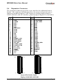
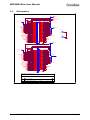
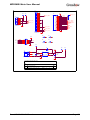
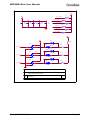
MPR - Mote Processor
Radio Board
MIB - Mote Interface /
Programming Board
User’s Manual
MPR500CA, MPR510CA
MPR400CB, MPR410CB
MPR300CA, MPR310CA
MIB300CA, MIB500CA
Rev. A, April 2003
Document 7430-0021-01
Crossbow Technology, Inc., 41 Daggett Dr., San Jose, CA 95134
Tel: 408-965-3300, Fax: 408-324-4840
email: [email protected], website: www.xbow.com
©2002-2003 Crossbow Technology, Inc. All rights reserved.
Information in this document is subject to change without notice.
Crossbow and SoftSensor are registered trademarks and DMU is a
trademark of Crossbow Technology, Inc. Other product and trade names
are trademarks or registered trademarks of their respective holders.
MPR/MIB Mote User Manual
1
Introduction.........................................................................3
2
MPR400/MPR410 (MICA2).................................................4
3
4
5
6
2.1
2.2
2.3
Powering the Mote..................................................................................4
Radio Antennae Considerations...........................................................5
Data Logger and Other Features...........................................................6
2.4
2.5
Expansion Connector..............................................................................7
Schematics................................................................................................8
MPR500/MPR510 (MICA2DOT).......................................12
3.1
Powering the Mote................................................................................12
3.2
3.3
3.4
Radio/Antennae.....................................................................................12
Data Logger............................................................................................12
Expansion Connector............................................................................12
3.5
Schematics..............................................................................................15
MPR300/MPR310 (MICA).................................................19
4.1
4.2
4.3
Powering the Mote................................................................................19
Radio/Antennae.....................................................................................19
Data Logger............................................................................................19
4.4
4.5
Expansion Connector............................................................................19
Schematics..............................................................................................20
MIB300 / MIB500 Interface Boards ...................................21
5.1
Programming the Mote.........................................................................21
5.2
5.3
RS-232 Interface....................................................................................22
Schematics..............................................................................................23
Warranty and Support Information...................................28
6.1
Customer Service ..................................................................................28
6.2
6.3
Contact Directory ..................................................................................28
Return Procedure...................................................................................28
6.3.1
6.3.2
6.3.3
6.3.4
6.3.5
Authorization ...................................................................................28
Identification and Protection...........................................................29
Sealing the Container ......................................................................29
Marking...........................................................................................29
Return Shipping Address.................................................................29
Doc. # 7430-0021-01 Rev. A
Page 1
MPR/MIB Mote User’s Manual
6.4
Page 2
Warranty.................................................................................................29
Doc. # 7430-0021-01 Rev. A
MPR/MIB Mote User Manual
1
Introduction
This User’s Manual describes the hardware features of the MICA and
MICA2 Motes. It is intended for understanding and leveraging the Mote
hardware design in real-world sensor network applications. This User’s
Manual also describes and explains the Mote Interface Boards (MIB) for
base station and programming requirements.
This manual is NOT a software guide to programming the Motes in
TinyOS/nesC, nor is it a guide to pre-built software packages that run on
top of the Motes. The following resources are available regarding software:
•
TinyOS Getting Started Guide by Crossbow
•
http://webs.cs.berkeley.edu/tos
Mote Hardware
Feature
MICA2
MPR400/410
MICA2DOT
MPR500/510
MICA
MPR300/310
10-Bit ADC
ü
ü
ü
Digital I/O
ü
ü
ü
UART
ü
ü
LEDS
3
3
ü
AM Radio
FM Tunable Radio
ü
Base Radio Frequency
(Mhz)
916/433
Flash Data Logger
Memory
ü
Antennae Connector
ü
3.3V Booster
Doc. # 7430-0021-01 Rev. A
1
ü
916/433
ü
916/433
ü
ü
Page 3
MPR/MIB Mote User’s Manual
2
MPR400/MPR410 (MICA2)
The MPR400 (916MHz) and MPR410 (433MHz) Series hardware is
Crossbow’s latest generation of Mote technology. Both the MPR400 and
MPR500 units utilize a powerful Atmega128L micro-controller and a
frequency tunable radio with extended range. The MPR400 and MPR500
radios are compatible and can communicate with each other.
2.1
Powering the Mote
The MPR400 is battery powered. The form factor of the MPR400 was
designed to match up with two AA batteries; however any battery
combination (AAA, C, D cells) can be used provided that the output is
between 2.7 – 3.3VDC.
Care should be used in selecting the battery and its capacity to match the
energy needs of the Motes and their deployment mission. Also make sure
that the temperature range and associated capacity degradation are looked at
prior to deployment. The section below provides some useful guidance on
how to predict battery life. The spreadsheet can be found at
http://www.xbow.comunder the Support section.
SYSTEM SPECIFICATIONS
Currents
Processor
current (full operation)
current sleep
Radio
current in receive
current transmit
current sleep
Logger Memory
Write
Example Duty Cycle
8mA
8uA
1
99
8mA
12mA
0.75
0.25
2uA
99
15mA
0
Read
Sleep
Sensor Board
4mA
2uA
0
100
current (full operation)
5mA
1
current sleep
5uA
Computed mA-hr used each hour
Processor
Page 4
99
0.0879
Doc. # 7430-0021-01 Rev. A
MPR/MIB Mote User Manual
Radio
Logger Memory
0.0920
0.0020
Sensor Board
Total current (mA-hr) used
0.0550
0.2369
Computed battery life vs. battery size
Battery Life (months)
Battery Capacity (mA-hr)
250
1.45
1000
3000
5.78
17.35
M WARNING
In most Mote applications, the processor and radio run for a brief period of
time, followed by a sleep cycle. During sleep, current consumption is
measured in micro amps as opposed to milliamps, and therefore battery life
is significantly extended. The result is very low-current draw for the
majority of the time, and short duration spikes while processing, receiving,
and transmitting data. This method does result in extended battery life;
however, due to the current surges, it also reduces specified battery
capacity. Battery capacity is generally specified for a nominal current
drawn constantly by the manufacturer.
2.2
Radio Antennae Considerations
Care should be taken to provide an antenna that provides proper coverage
for the environment expected. Range and performance are strongly affected
by choice of antenna and antenna placement within the environment. In
addition, care must be taken to ensure compliance with FCC article 15
regulations for intentional radiators. An omni directional antenna such as a
quarter wavelength whip should be sufficient to meet most user
requirements.
Antenna lengths for quarter wavelength whip antennas:
Unit
Whip Antenna Length(inches)
MPR400 (916 Mhz)
3.2
MPR410(433Mhz)
6.8
Doc. # 7430-0021-01 Rev. A
Page 5
MPR/MIB Mote User’s Manual
2.3 Data Logger and Other Features
The MICA2 Mote features a 4M-bit serial FLASH for storing data,
measurements, and other user-defined information. TinyOS supports a
micro file system that runs on top of this FLASH/Logger component. The
serial flash device supports over 100,000 Measurement readings. Also on
the MICA2 is a 64-bit serial ID chip.
Page 6
Doc. # 7430-0021-01 Rev. A
MPR/MIB Mote User Manual
2.4 Expansion Connector
The expansion connector provides a user interface for additional sensor
boards. The connector includes interfaces for power and ground, power
control of peripheral sensors, ADC inputs for reading sensor outputs, a
UART interface, and I2C interface, general purpose digital I/O, and others.
DESCRIPTION
PIN
1
2
3
4
5
6
7
8
9
10
11
12
13
14
15
16
17
18
19
20
21
22
23
24
25
26
GND
VSNSR
INT3
INT2
INT1
INT0
BAT_MON
LED3
LED2
LED1
RD
WR
ALE
PW7
USART1_CLK
PROG_MOSI
PROG_MISO
SPI_CLK
USART1_RXD
USART1_TXD
I2C_CLK
I2C_DATA
PWM0
PWM1A
AC+
AC -
DESCRIPTION
PIN
27
28
29
30
31
32
33
34
35
36
37
38
39
40
41
42
43
44
45
46
47
48
49
50
51
UART_RXD0
UART_TXD0
PW0
PW1
PW2
PW3
PW4
PW5
PW6
ADC7
ADC6
ADC5
ADC4
ADC3
ADC2
ADC1
ADC0
THERM_PWR
THRU1
THRU2
THRU3
RESETN
PWM1B
VCC
GND
26
51
1
27
1
27
26
51
Hirose: DF9-51(S,P)-1V(54)
Digikey: H2163-ND, H2175-ND
Doc. # 7430-0021-01 Rev. A
Page 7
MPR/MIB Mote User’s Manual
2.5
Schematics
R6
ADC7
TP3
10K
BT1
R7
BATTERY_2AA
U2
1
V+
3
18.2K
2
2
1
V-
BAT_MON
LM4041-1.2
VCC
R1
D1
R2
0 OHM
BAT54C
0 OHM
1 SW2
R3
VSNSR
2
3
R4
0 OHM
J4
1
2
0 OHM
SPDT
R5
1K
C2
.1uF
C1
.1uF
1
2
CONN
VSNSR
BOARD OPTIONS
R8
ADC[0..7]
ADC1
R1
R2
R4
R8
RT1
INSTALL
NOT INSTALLED
NOT INSTALLED
NOT INSTALLED
NOT INSTALLED
10K
RT1
10.0K
THERM_PWR
CROSSBOW TECHNOLOGY. INC.
Title
MICA2 MPR410CB-433MHZ
Page 8
Size
B
Document Number
6310-0306-01
Date:
Friday, March 21, 2003
Rev
A
Sheet
1
of
6
Doc. # 7430-0021-01 Rev. A
MPR/MIB Mote User Manual
RADIO CONTROL
AVCC
VCC
PCLK
PDATA
PALE
RADIO DATA
C5
0.033uF
SPI_SCK
SPI_MOSI
SPI_MISO
CHP_OUT
ADC0 (RSSI)
C6
.001uF
C7
.001uF
C8
220PF
C9
220PF
AVCC
C10
0.033uF
C11
.001uF
VCC
L1
BEAD-0805
L2
C12
AVCC
SPI_SCK
VCC
AVCC
23
24
25
26
27
DIO
DCLK
PCLK
PDATA
PALE
10
11
13
L4
21
C13
VCC
DCLK
PCLK
PDATA
PALE
AVCC
AVCC
AVCC
AVCC
U3
SPI_MISO
1
5
9
15
R12
10K
RF_IN
RF_OUT
CHP_OUT
RSSI
L1
L2
R_BIAS
XOSC1
XOSC2
L3
3
C14
4
12
28
CHP_OUT
MMCX
18
17
L5
1
ADC0
CC1000
R13
27.4K
C17
2
C16
.001uF
C18
4.7pF
3
C15
R14
82.5K
J5
Y4
1
1
2
14.7456MHZ
2
C19
13pF
C20
13pF
J3
1
2
VCC
1
2
HDR 2 X 1 X .1
R9
PALE
1M
R10
R11
1M
PDATA
Title
MICA2 MPR410CB-433MHZ
DCLK
Size
B
1M
Document Number
6310-0306-01
Date:
Rev
A
Friday, March 21, 2003
Sheet
2
of
6
PW[0..7]
UART_RXD0
UART_TXD0
VSNSR
INT3
INT2
INT1
INT0
BAT_MON
LED3
LED2
LED1
RD
WR
ALE
PW7
USART1_CLK
PROG_MOSI
PROG_MISO
SPI_SCK
USART1_RXD
USART1_TXD
I2C_CLK
I2C_DATA
PWM0
PWM1A
AC+
AC-
1
2
3
4
5
6
7
8
9
10
11
12
13
14
15
16
17
18
19
20
21
22
23
24
25
26
HIROSE PLUG
J21
INT[0..3]
27
28
29
30
31
32
33
34
35
36
37
38
39
40
41
42
43
44
45
46
47
48
49
50
51
UART_RXD0
UART_TXD0
PW0
PW1
PW2
PW3
PW4
PW5
PW6
ADC7
ADC6
ADC5
ADC4
ADC3
ADC2
ADC1
ADC0
THRU1
THRU2
THRU3
ADC[0..7]
THERM_PWR
RSTN
PWM1B
VCC
DF9-51P-1V(54)
PIN
NAME
1
2
3
4
5
6
7
8
9
10
11
12
13
14
15
16
17
18
19
20
21
22
23
24
25
26
GND
VSNSR
INT3
INT2
INT1
INT0
BAT_MON
LED3
LED2
LED1
RD
WR
ALE
PW7
USART1_CLK
PROG_MOSI
PROG_MISO
SPI_SCK
USART1_RXD
USART1_TXD
I2C_CLK
I2C_DATA
PWM0
PWM1A
AC+
AC-
DESCRIPTION
GROUND
SENSOR SUPPLY
GPIO
GPIO
GPIO
GPIO
BATTERY VOLTAGE MONITOR ENABLE
LED3
LED2
LED1
GPIO
GPIO
GPIO
POWER CONTROL 7
USART1 CLOCK
SERIAL PROGRAM MOSI
SERIAL PROGRAM MISO
SPI SERIAL CLOCK
USART1 RX DATA
USART1 TX DATA
I2C BUS CLOCK
I2C BUS DATA
GPIO/PWM0
GPIO/PWM1A
GPIO/AC+
GPIO/AC-
CROSSBOW TECHNOLOGY. INC.
Title
MICA2 MPR410CB-433MHZ
Size
B
Document Number
6310-0306-01
Date:
Friday, March 21, 2003
Doc. # 7430-0021-01 Rev. A
Rev
A
Sheet
3
of
6
Page 9
MPR/MIB Mote User’s Manual
PW[0..7]
VSNSR
INT3
INT2
INT1
INT0
BAT_MON
LED3
LED2
LED1
RD
WR
ALE
PW7
USART1_CLK
PROG_MOSI
PROG_MISO
SPI_SCK
USART1_RXD
USART1_TXD
I2C_CLK
I2C_DATA
PWM0
PWM1A
AC+
AC-
1
2
3
4
5
6
7
8
9
10
11
12
13
14
15
16
17
18
19
20
21
22
23
24
25
26
HIROSE SOCKET
J22
INT[0..3]
27
28
29
30
31
32
33
34
35
36
37
38
39
40
41
42
43
44
45
46
47
48
49
50
51
UART_RXD0
UART_TXD0
PW0
PW1
PW2
PW3
PW4
PW5
PW6
ADC7
ADC6
ADC5
ADC4
ADC3
ADC2
ADC1
ADC0
ADC[0..7]
THERM_PWR
THRU1
THRU2
THRU3
RSTN
PWM1B
PIN
NAME
27
UART_RXD0
UART_0 RECEIVE
28
29
30
UART_TXD0
PW0
PW1
UART_0 TRANSMIT
POWER CONTROL 0
POWER CONTROL 1
DESCRIPTION
31
32
33
PW2
PW3
PW4
POWER CONTROL 2
POWER CONTROL 3
POWER CONTROL 4
34
35
36
PW5
PW6
ADC7
POWER CONTROL 5
POWER CONTROL 6
ADC INPUT 7 - BATTERY MONITOR/JTAG TDI
37
38
39
ADC6
ADC5
ADC4
ADC INPUT 6 / JTAG TDO
ADC INPUT 5 / JTAG TMS
ADC INPUT 4 / JTAG TCK
40
41
42
ADC3
ADC2
ADC1
ADC INPUT 3
ADC INPUT 2
ADC INPUT 1
43
44
45
ADC0
THERM_PWR
THRU1
ADC INPUT 0 / RSSI MONITOR
TEMP SENSOR ENABLE
THRU CONNECT 1
46
47
48
THRU2
THRU3
RSTN
THRU CONNECT 2
THRU CONNECT3
RESET (NEG)
49
50
51
PWM1B
VCC
GND
GPIO/PWM1B
DIGITAL SUPPLY
GROUND
VCC
DF9B-51S-1V
M18
1
1
CROSSBOW TECHNOLOGY. INC.
MTG128
Title
M20
MICA2 MPR410CB-433MHZ
1
1
MTG128
Size
B
Document Number
6310-0306-01
Date:
Friday, March 21, 2003
Rev
A
Sheet
4
of
VSNSR
6
VCC
R15
C21
R16
470
C22
.1uF
10K
C23
.1uF
RSTN
64
62
20
.1uF
SPI_MOSI
R18
0 OHM
51
50
49
48
47
46
45
44
PW0
PW1
PW2
PW3
PW4
PW5
PW6
PW7
35
36
37
38
39
40
41
42
PA0/AD0
PA1/AD1
PA2/AD2
PA3/AD3
PA4/AD4
PA5/AD5
PA6/AD6
PA7/AD7
10
11
12
13
14
15
16
17
SPI_SCK
PWM0
PWM1A
PWM1B
R20
1
10K
10K
PC0/A8
PC1/A9
PC2/A10
PC3/A11
PC4/A12
PC5/A13
PC6/A14
PC7/A15
PE0/RXD0
PE1/TXD0
PE2/XCK0
PE3/OC3A
PE4/OC3B
PE5/OC3C
PE6/T3
PE7/IC3
PB0/SS
PB1/SCK
PB2/MOSI
PB3/MISO
PB4/OC0
PB5/OC1A
PB6/OC1B
PB7/OC1C
PF0/ADC0
PF1/ADC1
PF2/ADC2
PF3/ADC3
PF4/TCK
PF5/TMS
PF6/TDO
PF7/TDI
PEN
R21
SPI_MISO
PD0/I2C_CLK
PD1/I2C_DATA
PD2/RXD1
PD3/TXD1
PD4/IC1
PD5/XCK1
PD6/T1
PD7/T2
XTAL1
XTAL2
PG4/TOSC1
PG3/TOSC2
BAT_MON
CHP_OUT
THERM_PWR
PW[0..7]
FLASH_CS
SERIAL_ID
VCC
ATMEGA128L
PG0/WR
PG1/RD
PG2/ALE
X1
X1
I2C_CLK
I2C_DATA
USART1_RXD
USART1_TXD
PALE
USART1_CLK
PCLK
PDATA
2
3
4
5
6
7
8
9
INT0
INT1
INT2
INT3
UART_RXD0
UART_TXD0
AC+
AC-
ADC[0..7]
ADC0
ADC1
ADC2
ADC3
ADC4
ADC5
ADC6
ADC7
61
60
59
58
57
56
55
54
33
34
43
INT[0..3]
WR
RD
ALE
Y3
Y2
1
4
25
26
27
28
29
30
31
32
24
23
19
18
LED3
LED2
LED1
AVCC
AREF
RST
U7
X2
X2
2
3
4
3
X2
X1
GND GND
1
2
7.3728MHZ
C35
13pF
C36
13pF
32.768KHZ
CROSSBOW TECHNOLOGY. INC.
Title
MICA2 MPR410CB-433MHZ
Page 10
Size
B
Document Number
6310-0306-01
Date:
Friday, March 21, 2003
Rev
A
Sheet
5
of
6
Doc. # 7430-0021-01 Rev. A
MPR/MIB Mote User Manual
VCC
+
C24
10uF
10V
C25
.01uF
C26
.01uF
C27
.01uF
C28
.01uF
C29
.01uF
C30
.01uF
VCC
VCC
R19
USART1_RXD
C31
1000pF
C32
1000pF
C33
1000pF
C34
1000pF
R22
1M
UART_TXD0
R23
1M
FLASH_CS
VCC
USART1_TXD
USART1_CLK
FLASH_CS
U5
1
2
3
4
4.7K
8
SI
SO
SCK
RST
CS WP
USART1_RXD
VCC
5
D2
AT45DB041
U6
SERIAL_ID
2
R25
LED1 2
LED2
DQ
1
470
RED D3
2
R26
1
470
DS2401P
D4
RADIO CONTROL
FLASH INTERFACE
SENSOR INTERFACE
PCLK
PDATA
PALE
FLASH_SI
FLASH_SO
FLASH_CLK
SERIAL_ID
PW[0..7]
ADC[1..6]
GREEN
LED3 2
R27
1
470
RADIO DATA
UART INTERFACE
SPI_SCK
SPI_MOSI
SPI_MISO
CHP_OUT
ADC0
(RSSI)
UART_RXD0
UART_TXD0
YELLOW
VCC MONITOR
ADC7
CROSSBOW TECHNOLOGY. INC.
CONTROL INTERFACE
Title
I2C_CLK
I2C_DATA
Doc. # 7430-0021-01 Rev. A
MICA2 MPR410CB-433MHZ
Size
B
Document Number
6310-0306-01
Date:
Friday, March 21, 2003
Rev
A
Sheet
6
of
6
Page 11
MPR/MIB Mote User’s Manual
3
MPR500/MPR510 (MICA2DOT)
3.1 Powering the Mote
The MPR500 (916MHz) and MPR510 (433MHz) are battery powered. The
form factor of the MPR500 was designed to match up with a single coin
cell battery; however any battery combination (AAA, C, D cells) can be
used provided that the output is between 2.7 – 3.3VDC.
Care should be used in selecting the battery and its capacity to match the
energy needs of the Motes and their deployment mission. Also make sure
that the temperature range and associated capacity degradation are looked at
prior to deployment. The section below provides some useful guidance on
how to predict battery life. The spreadsheet can be found at
http://www.xbow.comunder the Support section.
3.2
Radio/Antennae
Care should be taken to provide an antenna that provides proper coverage
for the environment expected. Range and performance are strongly affected
by choice of antenna and antenna placement within the environment. In
addition, care must be taken to ensure compliance with FCC article 15
regulations for intentional radiators. Because of its small physical size, the
usual antenna chosen is a length of insulated wire one-quarter wavelength
long for the frequency of interest (~3.5 inches at 915 MHz, and ~8 inches at
433 MHz).
Antenna lengths for quarter wavelength whip antennas:
Unit
Whip Antenna Length (inches)
MPR400 (916 MHz)
3.2
MPR410 (433MHz)
6.8
3.3 Data Logger
The MICA2DOT Mote features a 4M -bit serial FLASH for storing data,
measurements, and other user-defined information. TinyOS supports a
micro file system that runs on top of this FLASH/Logger component. The
serial flash device supports over 100,000 Measurement readings.
3.4
Expansion Connector
The interface to the MPR500 is through a series of 19 pins spaced around
the circumference of the MPR500. They represent a subset of the pins
available on the MPR400. They include a set of power control pins, ADC
channels, power, ground, some general purpose digital IO, and the serial
programming port. For applications with more digital IO, the ADC pins
can be reconfigured as Digital Input/Output (but not both!).
Page 12
Doc. # 7430-0021-01 Rev. A
MPR/MIB Mote User Manual
M WARNING
The TP12 SPI_CK Pin is controlled by the Radio. In the majority of
applications it should not be used.
PIN
TP1
TP2
TP3
TP4
TP5
TP6
TP7
TP8
TP9
TP10
TP11
TP12
TP13
TP14
TP15
TP18
TP19
TP20
TP21
Doc. # 7430-0021-01 Rev. A
DESCRIPTION
GND
ADC7
ADC6
ADC5
ADC4
VCC
PW1
PW0
UART_TXD
UART_RXD
RESETN
SPI_CK
ADC3
ADC2
PWM1B
GND
INT1
INT0
THERM_PWR
Page 13
MPR/MIB Mote User’s Manual
Page 14
Doc. # 7430-0021-01 Rev. A
MPR/MIB Mote User Manual
3.5
Schematics
L3
C10
AVCC
SPI_SCK
VCCA
AVCC
DCLK
PCLK
PDATA
PALE
23
24
25
26
27
10
11
13
L8
R18
82.5K
DIO
DCLK
PCLK
PDATA
PALE
21
C12
VCC
SPI_MISO
AVCC
AVCC
AVCC
AVCC
U3
CC1000
1
5
9
15
R13
10K
RF_IN
RF_OUT
CHP_OUT
RSSI
L1
L2
R_BIAS
XOSC1
XOSC2
L4
3
C13
4
12
28
POT_PWR
18
17
TP17
C16
.001uF
C17
4.7pF
R17
27.4K
TP18
L9
ADC0
R35
10K
C18
C19
Y1
1
X1
X2
2
14.7456MHZ
INT3
C20
13pF
C21
13pF
VCCA
R10
AVCC
PALE
VCCA
1M
R11
R12
1M
PDATA
C3
0.033uF
C4
.001uF
C6
220PF
C9
.001uF
DCLK
1M
AVCC
VCCA
L2
BEAD-0805
Title
MICA DOT2 RADIO SIDE
Size
B
Date:
Doc. # 7430-0021-01 Rev. A
Document Number
6310-0300-01
Wednesday, March 26, 2003
Rev
A
Sheet
1
of
3
Page 15
MPR/MIB Mote User’s Manual
VCCA
C22
R21
.1uF
470
R22
10K
C23
VCCA
.1uF
35
36
37
38
39
40
41
42
10
11
12
13
14
15
16
17
SPI_SCK
SPI_MOSI
PWM0
PWM1A
PWM1B
R27
1
PB0/SS
PB1/SCK
PB2/MOSI
PB3/MISO
PB4/OC0
PB5/OC1A
PB6/OC1B
PB7/OC1C
PF0/ADC0
PF1/ADC1
PF2/ADC2
PF3/ADC3
PF4/TCK
PF5/TMS
PF6/TDO
PF7/TDI
VCCA
22
53
63
10K
PC0/A8
PC1/A9
PC2/A10
PC3/A11
PC4/A12
PC5/A13
PC6/A14
PC7/A15
PEN
R28
10K
SPI_MISO
25
26
27
28
29
30
31
32
PD0/INT0
PD1/INT1
PD2/RXD1
PD3/TXD1
PD4/IC1
PD5/XCK1
PD6/T1
PD7/T2
2
PE0/RXD0 3
PE1/TXD0 4
PE2/XCK0 5
PE3/OC3A 6
PE4/OC3B 7
PE5/OC3C
8
PE6/T3 9
PE7/IC3
XTAL1
XTAL2
PG4/TOSC1
PG3/TOSC2
PW0
PW1
PW2
PW3
PW4
PW5
PW6
PW7
GND
GND
GND
FLASH_CLK
I2C1_CLK
I2C1_DATA
FLASH_SO
FLASH_SI
PW[0..7]
PA0/AD0
PA1/AD1
PA2/AD2
PA3/AD3
PA4/AD4
PA5/AD5
PA6/AD6
PA7/AD7
24
23
19
18
51
50
49
48
47
46
45
44
LED3
LED2
LED1
VCC
VCC
AVCC
AREF
RST
21
52
64
62
20
RSTN
U6
INT0
INT1
INT2
SPI_MOSI
PALE
PCLK
PDATA
UART_RXD0
UART_TXD0
SERIAL_ID
61
60
59
58
57
56
55
54
ADC0
ADC1
ADC2
ADC3
ADC4
ADC5
ADC6
ADC7
33
34
43
PG0/WR
PG1/RD
PG2/ALE
INT3
AC+
ACDC_BOOST_SHDN
GPS_ENA
POT_PWR
ADC[0..7]
WR
RD
ALE
ATMEGA128LMLF
Y5
2
1
X2
X1
3
NC
32.768KHZ
Y4
1
2
3
X1
X1
GND GND
X2
X2
6
5
4
4.000MHZ
Title
MICA DOT2 CPU SIDE
Size
B
Date:
Page 16
Document Number
6310-0300-01
Wednesday, March 26, 2003
Rev
A
Sheet
2
of
3
Doc. # 7430-0021-01 Rev. A
MPR/MIB Mote User Manual
VCCA
R36
ADC1
VCCA
10K
D5
RT1
10.0K
C24
10uF
10V
+
SD103AW
C25
.01uF
C26
.01uF
PW7
PW6
VCCA
VCCA
R26
FLASH_SO
1M
R29
C31
1000pF
UART_TXD0
R30
C32
1000pF
1M
SERIAL_ID
4.7K
VCCA
D2
LED1
R31
2
1
470
RED
SERIAL_ID
U7
1
2
3
4
SI
SCK
RST
CS
GNDVCC
VCCA
FLASH_SI
FLASH_CLK
6
VCCA
SO
WP
8
FLASH_SO
5
7
AT45DB041
R25
100K
RSTN
Title
MICA DOT2 CPU SIDE
Size
B
Date:
Document Number
6310-0300-01
Wednesday, March 26, 2003
Doc. # 7430-0021-01 Rev. A
Rev
A
Sheet
2
of
3
Page 17
MPR/MIB Mote User’s Manual
TP7 TP8 TP9 TP10 TP11 TP12
TP1 TP2 TP3 TP4 TP5 TP6
VCCA
SPI_SCK
RSTN
UART_RXD0
UART_TXD0
ADC[0..7]
ADC4
ADC5
ADC6
ADC7
TP13 TP14 TP15
PW[0..7]
PW0
PW1
TP19 TP20 TP21
VCCA
1
PWM1B
ADC2
ADC3
GPS_ENA
INT1
INT0
2
BT1
BATTERY
Title
MICA DOT2 CPU SIDE
Size
B
Date:
Page 18
Document Number
6310-0300-01
Wednesday, March 26, 2003
Rev
A
Sheet
2
of
3
Doc. # 7430-0021-01 Rev. A
MPR/MIB Mote User Manual
4
MPR300/MPR310 (MICA)
4.1 Powering the Mote
The MPR300/MPR310 is battery powered. The form factor of the MPR300
was designed to match up with two AA batteries; however any battery
combination (AAA, C, D cells) can be used provided that the output is
between 2.7 – 3.3VDC.
Care should be used in selecting the battery and its capacity to match the
energy needs of the Motes and their deployment mission. Also make sure
that the temperature range and associated capacity degradation are looked at
prior to deployment. The section below provides some useful guidance on
how to predict battery life. The spreadsheet can be found at
http://www.xbow.comunder the Support section.
4.2
Radio/Antennae
Care should be taken to provide an antenna that provides proper coverage
for the environment expected. Range and performance are strongly affected
by choice of antenna and antenna placement within the environment. In
addition, care must be taken to ensure compliance with FCC article 15
regulations for intentional radiators. Because of its small physical size, the
usual antenna chosen is a length of insulated wire one-quarter wavelength
long for the frequency of interest (~3.5 inches at 915 MHz, and ~8 inches at
433 MHz).
4.3
Data Logger
The MICA Mote features a 4M -bit serial FLASH for storing data,
measurements, and other user-defined information. TinyOS supports a
micro file system that runs on top of this FLASH/Logger component. The
serial flash device supports over 100,000 Measurement readings. Also on
the MICA is a 64-bit serial ID chip.
4.4
Expansion Connector
The expansion connector provides a user interface for additional sensor
boards. The connector includes interfaces for power and ground, power
control of peripheral sensors, ADC inputs for reading sensor outputs, a
UART interface, and I2C interface, general purpose digital I/O, and others.
Doc. # 7430-0021-01 Rev. A
Page 19
MPR/MIB Mote User’s Manual
PIN
1
2
3
4
5
6
7
8
9
10
11
12
13
14
15
16
17
18
19
20
21
22
23
24
25
26
DESCRIPTION
GND
VDD_ANALOG
INT3
INT2
INT1
INT0
DC_BOOST_SHDN
LED3
LED2
LED1
RD
WR
ALE
PW7
FLASH_CLK
UART_RXD0
UART_TXD0
SPI_CLK
FLASH_SO
FLASH_SI
I2C_BUS1_CLK
I2C_BUS1_DATA
PWM0
PWM1A
AC+
AC-
PIN
27
28
29
30
31
32
33
34
35
36
37
38
39
40
41
42
43
44
45
46
47
48
49
50
51
DESCRIPTION
UART_RXD0
UART_TXD0
PW0
PW1
PW2
PW3
PW4
PW5
PW6
ADC7
ADC6
ADC5
ADC4
ADC3
ADC2
ADC1
ADC0
LITTLE_GUY_RST
LITTLE_GUY_SPI_CLK
LITTLE_GUY_MISO
UART_RXD0
RESET
PWM1B
VCC
GND
4.5 Schematics
Schematics for this Mote design are found at:
http://today.cs.berkeley.edu/tos/hardware/hardware.html
Page 20
Doc. # 7430-0021-01 Rev. A
MPR/MIB Mote User Manual
5
MIB300 / MIB500 Interface Boards
5.1 Programming the Mote
The MIB300/MIB500 interface boards are multi-purpose interface boards
used in conjunction with the MICA Family of products. They supply power
to the devices through an external power adapter option, and provide
interfaces for an RS232 serial port and reprogramming port (using the
parallel printer interface). The MIB300 can only be used with an external
3V supply, or it can take advantage of the battery power supplied from the
mote.
The MIB500 has an on-board regulator that will accept 5 to 15 VDC, and
supply a regulated 3V to the MICA. The MIB500 is delivered with a wall
power supply. It also has a monitor LEDs that mirror the LEDs on the
MICA.
There is a built-in low voltage monitor that disables reprogramming if the
power supply voltage is dangerously low. When the proper programming
voltage exists – the Green LED adjacent the parallel port is lit – D6. If the
voltage goes below 2.95V, the Green LED D6 will turn off, programming is
disabled. See Warning on Programming Motes.
The MIB500 also has an interface connector for reprogramming the
MICA2DOT.
Programming the mote is accomplished by connecting the
MIB300/MIB500 to the parallel port of the computer, and executing the
required programming software – UISP - supplied with the TinyOS install.
M WARNING
When programming a MICA2 with the MIB500, turn off the battery switch.
For a MICA2DOT, remove the battery before inserting into the MIB500.
The MICA2s and MICA2DOTs do not have switching diodes to switch
between external and battery power.
M WARNING
There have been numerous reported difficulties with programming Motes.
These include program failure, flash verification errors, and dead Motes.
The root cause of these problems is almost always one of two is sues – low
Doc. # 7430-0021-01 Rev. A
Page 21
MPR/MIB Mote User’s Manual
programming voltage or UISP problems on the Host PC. A detailed
application note is posted at http://www.xbow.com under Support. Please
review this application note, if you have trouble programming.
Programming the Motes improperly or with a bad UISP install can result in
permanent damage to the Mote CPU.
5.2 RS-232 Interface
The RS232 interface is a standard single channel bi-directional interface
with a DB9 connector to interface to an external computer. It uses transmit
and receive lines only.
Page 22
Doc. # 7430-0021-01 Rev. A
MPR/MIB Mote User Manual
5.3
Schematics
PW[0..7]
UART_RXD0
UART_TXD0
VSNSR
J2
BAT_MON
LED3
LED2
LED1
RD
WR
ALE
PW7
USART1_CLK
PROG_MOSI
PROG_MISO
SPI_SCK
USART1_RXD
USART1_TXD
I2C_CLK
I2C_DATA
PWM0
PWM1A
AC+
AC-
1
2
3
4
5
6
7
8
9
10
11
12
13
14
15
16
17
18
19
20
21
22
23
24
25
26
PLUG
INT3
INT2
INT1
INT0
HIROSE
INT[0..3]
27
28
29
30
31
32
33
34
35
36
37
38
39
40
41
42
43
44
45
46
47
48
49
50
51
UART_RXD0
UART_TXD0
PW0
PW1
PW2
PW3
PW4
PW5
PW6
ADC7
ADC6
ADC5
ADC4
ADC3
ADC2
ADC1
ADC0
ADC[0..7]
M1
1
M2
THERM_PWR
THRU1
THRU2
THRU3
1
MTG128
1
1
MTG128
RSTN
PWM1B
VCC
PW[0..7]
DF9-51P-1V(54)
VSNSR
INT3
INT2
INT1
INT0
BAT_MON
LED3
LED2
LED1
RD
WR
ALE
PW7
USART1_CLK
PROG_MOSI
PROG_MISO
SPI_SCK
USART1_RXD
USART1_TXD
I2C_CLK
I2C_DATA
PWM0
PWM1A
AC+
AC-
1
2
3
4
5
6
7
8
9
10
11
12
13
14
15
16
17
18
19
20
21
22
23
24
25
26
HIROSE SOCKET
J1
INT[0..3]
27
28
29
30
31
32
33
34
35
36
37
38
39
40
41
42
43
44
45
46
47
48
49
50
51
UART_RXD0
UART_TXD0
PW0
PW1
PW2
PW3
PW4
PW5
PW6
ADC7
ADC6
ADC5
ADC4
ADC3
ADC2
ADC1
ADC0
ADC[0..7]
THERM_PWR
THRU1
THRU2
THRU3
RSTN
PWM1B
VCC
DF9B-51S-1V
CROSSBOW TECHNOLOGY. INC.
Title
MIB500CA MICA PROG BOARD
Size
B
Document Number
6310-0304-01
Date:
Wednesday, March 26, 2003
Doc. # 7430-0021-01 Rev. A
Rev
A
Sheet
1
of
3
Page 23
MPR/MIB Mote User’s Manual
PIN
1
2
3
4
5
6
7
8
9
10
11
12
13
14
15
16
17
18
19
20
21
22
23
24
25
26
NAME
GND
VSNSR
INT3
INT2
INT1
INT0
BAT_MON
LED3
LED2
LED1
RD
WR
ALE
PW7
USART1_CLK
PROG_MOSI
PROG_MISO
SPI_SCK
USART1_RXD
USART1_TXD
I2C_CLK
I2C_DATA
PWM0
PWM1A
AC+
AC-
PIN
NAME
27
28
29
30
31
32
33
34
35
36
37
38
39
40
41
42
43
44
45
46
47
48
49
50
51
UART_RXD0
UART_TXD0
PW0
PW1
PW2
PW3
PW4
PW5
PW6
ADC7
ADC6
ADC5
ADC4
ADC3
ADC2
ADC1
ADC0
THERM_PWR
THRU1
THRU2
THRU3
RSTN
PWM1B
VCC
GND
DESCRIPTION
GROUND
SENSOR SUPPLY
GPIO
GPIO
GPIO
GPIO
BATTERY VOLTAGE MONITOR ENABLE
LED3
LED2
LED1
GPIO
GPIO
GPIO
POWER CONTROL 7
USART1 CLOCK
SERIAL PROGRAM MOSI
SERIAL PROGRAM MISO
SPI SERIAL CLOCK
USART1 RX DATA
USART1 TX DATA
I2C BUS CLOCK
I2C BUS DATA
GPIO/PWM0
GPIO/PWM1A
GPIO/AC+
GPIO/AC-
DESCRIPTION
UART_0 RECEIVE
UART_0 TRANSMIT
POWER CONTROL 0
POWER CONTROL 1
POWER CONTROL 2
POWER CONTROL 3
POWER CONTROL 4
POWER CONTROL 5
POWER CONTROL 6
ADC INPUT 7 - BATTERY MONITOR/JTAG TDI
ADC INPUT 6 / JTAG TDO
ADC INPUT 5 / JTAG TMS
ADC INPUT 4 / JTAG TCK
ADC INPUT 3
ADC INPUT 2
ADC INPUT 1
ADC INPUT 0 / RSSI MONITOR
TEMP SENSOR ENABLE
THRU CONNECT 1
THRU CONNECT 2
THRU CONNECT3
RESET (NEG)
GPIO/PWM1B
DIGITAL SUPPLY
GROUND
CROSSBOW TECHNOLOGY. INC.
Title
MIB500CA MICA PROG BOARD
Page 24
Size
B
Document Number
6310-0304-01
Date:
Wednesday, March 26, 2003
Rev
A
Sheet
1
of
3
Doc. # 7430-0021-01 Rev. A
MPR/MIB Mote User Manual
J4
TP5
13
25
12
24
11
23
10
22
9
21
8
20
7
19
6
18
5
17
4
16
3
15
2
14
1
TP6
J6
5
9
4
8
3
7
2
6
1
RS232_RX
RS232_TX
DB9-F-RA
VCC
J5
LPT1_MISO
1
2
3
4
5
6
7
8
9
10
11
12
13
14
15
16
17
18
19
LPT1_RST
LPT1_MOSI
LPT1_SCK
ADC[0..7]
1
2
3
4
5
6
7
8
9
10
11
12
13
14
15
16
17
18
19
ADC7
ADC6
ADC5
ADC4
ADC3
ADC2
UART_RXD0
UART_TXD0
THERM_PWR
PWM1B
RSTN
INT0
INT1
SPI_SCK
PW0
PW1
DOT2
DB25-M-RA
M3
TDI
ADC7
1
3
5
7
9
HDR2X5
ADC4
ADC6
ADC5
1
MTG128
J3
TCK
TDO
TMS
M4
1
1
VCC
2
4
6
8
10
M5
RSTN
1
MTG128
M6
1
1
1
MTG128
1
MTG128
TP7
D1
TP8
TP9
VCC
J7
B2100
PIN
1
OUTER
U1
3
3
2
C1
.1uF
50V
1
VIN
VOUT
ADJ
GND
2
4
+
C2
10uF
35V
LMS8117-3.3
PJ-014D
CROSSBOW TECHNOLOGY. INC.
Title
MIB500CA MICA PROG BOARD
Size
B
Document Number
6310-0304-01
Date:
Wednesday, March 26, 2003
Doc. # 7430-0021-01 Rev. A
Rev
A
Sheet
2
of
3
Page 25
MPR/MIB Mote User’s Manual
TP4
TP2
VCC
U2
5
2
LPT1_MOSI
VCC
4
1
NC7SZ125
C8
VCC
U3
VCC
U4
5
.1uF
2
VCC
R1IN R1OUT
R2IN R2OUT
T1OUT
T1IN
T2OUT
T2IN
16
9
17
8
RS232_RX
RS232_TX
14
20
FON READY
FOFF
INVD
2
4
3
C9
.1uF
C11
.1uF
20%
50V
C1+
C1V+
C2+
C2V-
19
15
10
13
12
TP1
4
NC7SZ126
U5
UART_TXD0
1
11
VCC
5
2
5
6
7
UART_RXD0
1
4
LPT1_MISO
1
C10
.1uF
20%
50V
C12
.1uF
20%
50V
MAX3224
NC7SZ125
VCC
U6
4
SPI_SCK
1
NC7SZ125
5
2
5
2
LPT1_SCK
VCC
U7
TP3
R7
4
RSTN
1
LPT1_RST
1.00K
SW1
NC7SZ125
1
5
2
3
4
PB SPST
3
VCC
U9
LM4041-1.2
VCC
R10
2
1
5
R9
18.2K
3
1
+
U11
TL331DBV
U12
VCC
5
D6
100K
4
2
-
R12
4
1
470
GREEN
R15
33.2K
26.1K
NC7SZ125
2
R14
CROSSBOW TECHNOLOGY. INC.
Title
MIB500CA MICA PROG BOARD
Page 26
Size
B
Document Number
6310-0304-01
Date:
Wednesday, March 26, 2003
Rev
A
Sheet
3
of
3
Doc. # 7430-0021-01 Rev. A
MPR/MIB Mote User Manual
VCC
R1
LPT1_MOSI
VCC
R2
100K
100K
R3
R4
100K
100K
R5
R6
100K
LPT1_SCK
C3
.1uF
C4
.1uF
C5
.1uF
C6
.1uF
LPT1_RST
C7
.1uF
RSTN
SPI_SCK
UART_RXD0
100K
VCC
VCC
U8
2
LED1
5
D2
D3
RED
RED
D4
D5
YELLOW
NC7SZ125
U10
2
5
200
R11
4
1
U13
2
200
YELLOW D7
NC7SZ125
LED2
R8
4
1
LED3
R16
0
5
D8
R13
GREEN
4
1
200
NC7SZ125
GREEN
CROSSBOW TECHNOLOGY. INC.
Title
MIB500CA MICA PROG BOARD
Size
B
Document Number
6310-0304-01
Date:
Wednesday, March 26, 2003
Doc. # 7430-0021-01 Rev. A
Rev
A
Sheet
3
of
3
Page 27
MPR/MIB Mote User’s Manual
6
Warranty and Support Information
6.1 Customer Service
As a Crossbow Technology customer you have access to product support
services, which include:
6.2
•
Single -point return service
•
Web-based support service
•
Same day troubleshooting assistance
•
Worldwide Crossbow representation
•
Onsite and factory training available
•
Preventative maintenance and repair programs
•
Installation assistance available
Contact Directory
United States:
Phone: 1-408-965-3300 (7 AM to 7 PM PST)
Non-U.S.:
6.3
Fax:
1-408-324-4840 (24 hours)
Email: [email protected]
refer to website www.xbow.com
Return Procedure
6.3.1
Authorization
Before returning any equipment, please contact Crossbow to obtain a
Returned Material Authorization number (RMA).
Be ready to provide the following information when requesting a RMA:
•
Name
•
Address
•
Telephone, Fax, Email
•
Equipment Model Number
•
Equipment Serial Number
•
Installation Date
•
Failure Date
•
Fault Description
Page 28
Doc. # 7430-0021-01 Rev. A
MPR/MIB Mote User Manual
6.3.2
Identification and Protection
If the equipment is to be shipped to Crossbow for service or repair, please
attach a tag TO THE EQUIPMENT, as well as the shipping container(s),
identifying the owner. Also indicate the service or repair required, the
problems encountered, and other information considered valuable to the
service facility such as the list of information provided to request the RMA
number.
Place the equipment in the original shipping container(s), making sure there
is adequate packing around all sides of the equipment. If the original
shipping containers were discarded, use heavy boxes with adequate padding
and protection.
6.3.3
Sealing the Container
Seal the shipping container(s) with heavy tape or metal bands strong
enough to handle the weight of the equipment and the container.
6.3.4
Marking
Please write the words, “FRAGILE, DELICATE INSTRUMENT” in
several places on the outside of the shipping container(s). In all
correspondence, please refer to the equipment by the model number, the
serial number, and the RMA number.
6.3.5
Return Shipping Address
Use the following address for all returned products:
Crossbow Technology, Inc.
41 Daggett Drive
San Jose, CA 95134
Attn: RMA Number (XXXXXX)
6.4
Warranty
The Crossbow product warranty is one year from date of shipment.
Doc. # 7430-0021-01 Rev. A
Page 29
Crossbow Technology, Inc.
41 Daggett Drive
San Jose, CA 95134
Phone: 408.965.3300
Fax: 408.324.4840
Email: [email protected]
Website: www.xbow.com