1
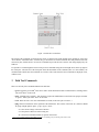
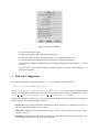
Tiny Application Sensor Kit (TASK) Field Tool User Manual
David Gay, Intel Research
[email protected]
March 19, 2003
1
Introduction
The field tool is a simple tool for debugging TASK-based sensor networks “in the field”. The field tool allows a user
to walk up to a TASK-mote and inspect or modify its state by issuing a set of simple commands. The field tool only
operates on the motes that are in direct radio range (i.e., close proximity) to the user.
The field tool runs on handhelds devices (currently HP Ipaq’s running Linux) equipped with a Canby or Canby2
compact-flash mote.
2
Mode of Operation
Before the first use, the field tool should be configured as explained in Section 4.
Once started, the field tool presents the user with the screen shown in Figure 1. The top-left pane is a list of commands
(“command pane”) that can be sent to the mote, the top-right pane is a list of the motes (“mote pane”) that the field
tool has discovered in the local neighbourhood, the bottom pane (“result pane”) displays the results returned of field
tool commands as returned by the motes.
TASK-motes spend most of their time asleep; they will not discover (and be discovered by) the field tool until the next
time they wake up. Once a mote notices the field tool, it will turn on its yellow LED1 and switch to an “always-on”
state. Simultaneously, assuming no radio problems, the field tool will update the list of motes known to be in the
neighbourhood (top-right pane).
The field tool advertises its presence by sending periodic messages. The interval between these periodic messages can
be changed with the field tool configurator (Section 4). If a mote does not hear from the field tool for 20s, it assumes
that it can return to normal operation, turns off its yellow LED, and resumes its regular sleep/wake schedule. Similarly,
if the field tool does not hear from a mote for 10s (or the “Mote Timeout” value chosen using the configurator), it
assumes that the mote is no longer in proximity to the field tool and removes it from the mote list in the top-right pane.
Sending commands to motes is straightforward:
1. Select a specific mote from the mote list, or select “ALL” to send a command to all motes in the range of the
field tool (which should be the same as those shown in the mote list).
2. Execute the desired command by clicking on its button in the top-left command pane.
1 mica2dot
motes do not have yellow LEDs, so you won’t see anything.
1
Figure 1: Field Tool User Interface.
The results of the command, as returned by the motes, are shown in the result (bottom) pane. Results are of the form
“mote number: command results”, with one entry per mote that received the command. Note that problems with radio
connectivity may lead the mote to execute the command, but prevent the mote’s answer from being displayed by the
field tool.
It is possible to scroll through the answers from previous commands using the left and right arrows at the top-right of
the result pane. The title area of the result pane shows the destination of the command (ALL or a mote number), the
command name and the time the command was executed. The results from the latest command are displayed in red,
without a time.
3
Field Tool Commands
There are currently four commands defined in the field tool:
• green: toggle the green LED.2 This can be used to check that field tool/mote communication is working. Motes
just return “done” as the result.
• beep: sound the mote’s sounder – this obviously requires the standard mica sensor board. The purpose is similar
to “green”. Motes just return “done” as the result.
• reset: Reset the mote. Note: this command has no result (as the mote just reset itself...).
• ping: Return vital statistics on the operation of the TASK-mote. The result is of the form “X V, Parent N, RAM
R, qln Q, mhq M, dpth D, qual L, q1 Q1, q2 Q2”, where:
– X is the current voltage of the mote’s batteries.
– N is the parent of this mote in the routing tree.
– R is the amount of RAM available for queries on this mote.
2 mica2dot
motes do not have green LEDs, so you won’t see anything, but you will still get the “done” result.
2
Figure 2: Field Tool Configurator.
– Q is the radio send queue length.
– M is the forward queue length of the multi-hop routing layer.
– D is the depth of the mote in the multi-hop routing tree, i.e., the number of hops to root.
– L is the link quality of the current parent node. The metric is routing layer-dependent.
– Q1 is the query id of the first TinyDB query currently running, typically the TASK sensor query. −1 means
no query.
– Q2 is the query id of the second TinyDB query currently running, typically the TASK health query. −1
means no second query.
4
Field Tool Configuration
The Canby mote should be programmed with the GenericBase application, programmed with
make <motekind> -DCANBY MSG_SIZE=49
where <motekind> is mica or mica2. On mica2s and mica2dots, if you’re not using the default 433MHz
channel, you should make sure that you have selected the correct radio frequency either in your Makelocal file, or via
-DCC1K DEF FREQ=<DesiredFreq> or -DCC1K DEF PRESET=<Index> ncc options.
The field tool configurator must be used to set up important field tool parameters. The interface of this configurator is
shown in Figure 2. The following parameters can be set:
• Serial or IP: choose whether the field tool communicates with the Canby mote (or equivalent) over IP or via a
serial port. This should normally be left at “Serial”.
• Host/Serial: Hostname for IP communication when IP is chosen, serial port name when Serial is chosen.
Normally “/dev/tts/0”.
• Port/Baud: Portname for IP communication, baud rate for serial communications (mica-based Canby motes
use 19200 baud, mica2-based Canby motes use 57600 baud).
3
• Group: group id of the TASK motes. You must set this to match the group ID of your generic sensor kit
deployment. Also, the Canby mote must be programmed with this group ID.
• Local Id: ID for the field tool. Should be different from any TASK-mote ID.
• Msg Size: Mote radio message size. Must be 56.
• Command Period: the commands selected by the user are sent multiple times to ensure reception by the motes.
This value is the interval in ms at which messages are repeated. Normally 500ms.
• Command Count: the number of times commands selected by the user are sent. Normally 3.
• Wakeup Period: the interval (in ms) between the messages the field tool sends to advertise its presence to
motes. Must be smaller than half the normal awake period of the motes, or they will not notice the field tool.
• Mote Timeout: interval (in ms) after which motes which have not been heard by the field tool are removed
from the mote list. Default is 10s. This should be at least twice the wakeup period to avoid motes constantly
appearing and disappearing from the mote list.
4