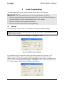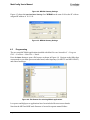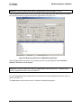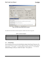
1
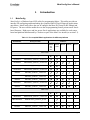
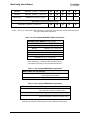
MoteConfig User’s Manual
Revision B, March 2007
PN: 7430-0112-01
© 2006 - 2007 Crossbow Technology, Inc. All rights reserved.
Information in this document is subject to change without notice.
Crossbow, MoteWorks, MICA, TrueMesh and XMesh are registered trademarks of Crossbow
Technology, Inc. Other product and trade names are trademarks or registered trademarks of their
respective holders
MoteConfig User’s Manual
Table of Contents
1
2
Introduction.............................................................................................................................1
1.1
MoteConfig.................................................................................................................... 1
1.2
Over – The – Air – Programming (OTAP) .................................................................... 3
Installation...............................................................................................................................4
2.1
Supported Platforms ...................................................................................................... 4
2.2
PC Interface Port Requirements..................................................................................... 4
2.3
Installation Steps............................................................................................................ 5
3
Starting MoteConfig...............................................................................................................6
4
Local Programming................................................................................................................7
5
4.1
Settings .......................................................................................................................... 7
4.2
Programming ................................................................................................................. 8
4.3
Fuse Settings ................................................................................................................ 10
4.4
Address and Radio Defaults ........................................................................................ 11
4.5
Remote XServe Connection......................................................................................... 12
Over-The-Air-Programming (OTAP) ................................................................................13
5.1
OTAP Enable............................................................................................................... 13
5.2
Over-the-Air-Programming ......................................................................................... 15
5.3
Advanced Options........................................................................................................ 23
A. Port Assignment on MIB programming Boards ...............................................................24
Doc.# 7430-0112-01 Rev. B
Page i
MoteConfig User’s Manual
About This Document
The following annotations have been used to provide additional information.
; NOTE
Note provides additional information about the topic.
; EXAMPLE
Examples are given throughout the manual to help the reader understand the terminology.
3 IMPORTANT
This symbol defines items that have significant meaning to the user
0 WARNING
The user should pay particular attention to this symbol. It means there is a chance that physical
harm could happen to either the person or the equipment.
The following paragraph heading formatting is used in this manual:
1 Heading 1
1.1 Heading 2
1.1.1 Heading 3
This document also uses different body text fonts (listed in Table 0-1) to help you distinguish
between names of files, commands to be typed, and output coming from the computer.
Table 0-1. Font types used in this document.
Font Type
Usage
Courier New Normal
Sample code and screen output
Courier New Bold
Commands to be typed by the user
Times New Roman Italic TinyOS files names, directory names
Franklin Medium Condensed
Page ii
Text labels in GUIs
Doc.# 7430-0112-01 Rev. B
MoteConfig User’s Manual
1
1.1
Introduction
MoteConfig
MoteConfig is a Windows-based GUI utility for programming Motes. This utility provides an
interface for configuring and downloading pre-compiled XMesh/TinyOS firmware applications
onto Motes. MoteConfig allows the user to configure the Mote ID, Group ID, RF channel and
RF power. The user can also enable the over-the-air-programming feature present on all Xmesh based firmware. High-power and low-power Xmesh applications are available for each sensor
board and platform manufactured by Crossbow as part of the MoteView install (see section 2.3).
Table 1-1. Pre-compiled XMesh applications for different platforms
Board Model
Binary file name
Platforms
MICA2
315
433
915
MICAZ
2400
M9100
M2100
M2110
9
9
9
9
9
9
MTS boards
MTS101
XMTS101_<platform>_<mode>.exe
9
9
MTS300CA
XMTS300CA_<platform>_<mode>.exe
9
9
MTS300CB
XMTS300CB_<platform>_<mode>.exe
9
9
MTS310CA
XMTS310CA_<platform>_<mode>.exe
9
9
MTS310CB
XMTS310CB_<platform>_<mode>.exe
9
9
MTS400
XMTS400_<platform>_<mode>.exe
9
9
MTS410
XMTS410_<platform>_<mode>.exe
9
9
MTS420
XMTS420_<platform>_<mode>.exe
9
9
9
9
9
MTS420CC
XMTS420CC_<platform>_<mode>.exe
9
9
9
9
9
MTS450
XMTS450_<platform>_<mode>.exe
9
9
9
9
9
9
9
9
9
9
9
MDA boards
MDA100CA
XMDA100CA_<platform>_<mode>.exe
9
9
MDA100CB
XMDA100CB_<platform>_<mode>.exe
9
9
XBW-DA100CA
XBW-DA100CA_<platform>_hp.exe
9
XBW-DA100CB
XBW-DA100CB_<platform>_hp.exe
9
MDA300
XMDA300_<platform>_<mode>.exe
Doc.# 7430-0112-01 Rev. B
9
9
Page 1
MoteConfig User’s Manual
MDA300P
XMDA300p_<platform>_<mode>.exe
9
9
9
9
9
MDA320
XMDA320_<platform>_<mode>.exe
9
9
9
9
9
XBW-DA325
XBW-DA325_<platform>_hp.exe
9
9
9
9
Base Station (common to all sensor boards)
9
XMeshBase_<platform>_<mode>.exe
9
<platform> = 315, 433, 915 (for MICA2), 2400 (for MICAz), or M9100, M2100, M2110
<mode> = hp or lp. hp = high power mesh networking. lp = low-power mesh networking via low-power listening and
time synchronized data transmissions.
Table 1-2. Pre-compiled MICA2DOT XMesh Applications
MICA2DOT Mote (MPR5x0, x = 0, 1, or 2)
Board Model
Binary file name
MTS boards
MTS510
XMTS510_xxx_<mode>.exe
MDA boards
MDA500
XMDA500_xxx_<mode>.exe
Base Station (common to all boards)
XMeshBase_Dot_xxx_<mode>.exe
xxx = 315, 433, or 915. <mode> = hp or lp. hp = high power
mesh networking. lp = low-power mesh networking via lowpower listening and time synchronized data transmissions.
Table 1-3. Pre-compiled MSP XMesh applications
MSP410 Mote Security Package
MSP410_433_base.exe
MSP410_433_hp.exe
To be used on an MPR410 MICA2 Mote
connected to the base station
For the MSP410 Mote
Table 1-4. Pre-compiled MEP XMesh applications
MEP410 Mote Environmental Package
MEP410_433_<mode>.exe
For the MEP410 and an MPR410 MICA2 Mote
when assigned a node ID of 0 (“base node”).
MEP510 Mote Environmental Package
MEP510_433_<mode>.exe
For the MEP510 and an MPR510 MICA2DOT
Mote when assigned a node ID of 0 (“base node”).
<mode> = hp or lp. hp = high power mesh networking. lp = low power mesh
networking via low-power listening and time synchronized data transmissions.
Page 2
Doc.# 7430-0112-01 Rev. A
MoteConfig User’s Manual
1.2
Over – The – Air – Programming (OTAP)
The Over-The-Air-Programming (OTAP) feature allows users to reprogram a Mote over a
wireless channel. OTAP allows one or more Motes in the XMesh network to receive new
firmware images from XServe (via the XOtap service).
Figure 1-1: XOTAP Architecture
Each mote has a 512kB external non-volatile flash separated into 4 slots. These slots have a
default size of 128 kB. Slot 0 is reserved for the OTAP image. Slots 1, 2 and 3 can be used for
user-specified firmware.
During the OTAP process, the server sends a command to the Mote to reboot into the OTAP
image (slot 0). A user-specified firmware image is broken up into fragments and transmitted to
the Mote and stored into Slot 1, 2 or 3. The server can send a message to transfer the newly
uploaded firmware into the program flash and reboot the Mote.
The following components are required for OTAP to work:
-
Xserve and XOtap running on the server
-
Firmware applications that include the XOTAPLiteM component (this is automatically
included when the firmware is built with Xmesh)
-
The mote needs to have pre-configured with a bootloader in the program flash, and the
OTAP image in slot 0 of the external flash. Both of these conditions are met by selecting
OTAP enable during the MoteConfig download process outlined in Section 4.
Doc.# 7430-0112-01 Rev. B
Page 3
MoteConfig User’s Manual
2
2.1
Installation
Supported Platforms
MoteConfig is supported on the following operating systems:
• Windows XP Home
• Window XP Professional
• Windows 2000 with SP4
2.2
PC Interface Port Requirements
The gateway platform used in the base station determines the PC interface port required by
MoteConfig.
1. For a MIB510 serial gateway: an RS-232 serial port.
2. For a MIB520 USB gateway: a USB port.
3. For a MIB600 Ethernet gateway: A wired Ethernet or 802.11 wireless card (if the
MIB600 is on a LAN with wireless access).
4. For a Stargate server: A wired Ethernet, an 802.11 wireless card (if the Stargate has a
wireless modem or is on a LAN with wireless access), or a cellular modem for wireless
Internet access.
Page 4
Doc.# 7430-0112-01 Rev. A
MoteConfig User’s Manual
2.3
Installation Steps
MoteConfig is shipped as a component of MoteView and MoteWorks:
1. MoteConfig is automatically installed with MoteView. Refer to the MoteView Users
Manual for additional details.
2. MoteConfig is an optional component in the MoteWorks installer. Make sure that
MoteConfig 2.0 and OTAP item is selected as shown in Figure 2-1.
Figure 2-1: MoteConfig 2.0 and OTAP – MoteWorks Installer
Doc.# 7430-0112-01 Rev. B
Page 5
MoteConfig User’s Manual
3
Starting MoteConfig
Figure 3-1: MoteConfig Application GUI
If MoteConfig was installed using the MoteView installer, use the following steps:
-
Open MoteView1.4C by either clicking on the shortcut located on the Desktop, or by
going to Start > Programs > Crossbow > MoteView 1.4C.
-
Press the Program Mote button (
GUI as shown in Figure 3-1
) on the MoteView toolbar to spawn the MoteConfig
If MoteConfig was installed using the MoteWorks installer
-
Page 6
Click on the shortcut located on the Desktop, or select Start > Programs > Crossbow > MoteConfig 2.0.
Doc.# 7430-0112-01 Rev. A
MoteConfig User’s Manual
4
Local Programming
The Local Program tab is used to upload firmware onto the Motes via the gateway.
3 IMPORTANT: To program motes correctly, set up the hardware as follows:
1. The gateway should be powered and connected to the PC via a serial, USB or Ethernet port.
2. If using the MIB510, the SW2 switch should be in the “OFF” position.
3. The motes should be firmly attached to the gateway.
4. The motes should be turned off before the programming.
4.1
Settings
Click on Settings > Interface Board... to select the correct gateway and port settings.
; NOTE: The default baud rate for the MICA2 and MICAz is 57600. The default baud rate for
the MICA2DOT is 19200.
Figure 4-1 shows the Interface Board Settings for a MIB510 on COM 1.
Figure 4-1: MIB510 Gateway Settings
For information on port assignment on MIB programming boards refer Appendix A. The
MIB520 virtual COM port drivers will install two sequential ports on the PC. The lownumbered port is used for programming and the high-numbered port is used for communication.
Figure 4-2 shows the Interface Board Settings for a MIB520 that has created COM 6 and 7 on the
PC. In this example, COM 6 must be selected as the serial port.
Doc.# 7430-0112-01 Rev. B
Page 7
MoteConfig User’s Manual
Figure 4-2: MIB520 Gateway Settings
Figure 4-3 shows the Interface Board Settings for a MIB600 on the same LAN as the PC with an
assigned IP address of 10.1.1.99.
Figure 4-3: MIB600 Gateway Settings
4.2
Programming
The pre-compiled XMesh applications installed with MoteView are located in C > Program
Files > Crossbow > MoteView > Xmesh.
Press the Select button to open a file browser as shown in Figure 4-4. Navigate to the folder that
corresponds to your Mote processor/radio board, radio frequency (for MICA2 and MICA2DOT)
and sensor board type.
Figure 4-4: File Browser for selecting XMesh applications.
Low-power and high-power applications have been included for most sensor boards.
Note that the MEP and MSP node firmware is located in separate named folders.
Page 8
Doc.# 7430-0112-01 Rev. A
MoteConfig User’s Manual
; NOTE: The base station mote must be programmed with XMeshBase_xxx.exe.
After an application has been selected, the binary scan feature built into MoteConfig will display
the default parameters programmed into the application (see Figure 4-5).
Figure 4-5: Binary Scan Result of an XMeshBase application
These default parameters can be overwritten by the user by specifying the desired MOTE ID,
GROUP ID, RF Power, and RF Channel.
; NOTE: The base station mote must be programmed with a Mote ID of 0. Remote nodes
must be programmed with a non-zero Mote ID.
Press the Program button to download the selected firmware and configuration into the mote, as
shown in Figure 4-6.
The Stop button can be used to cancel a firmware download in progress.
Doc.# 7430-0112-01 Rev. B
Page 9
MoteConfig User’s Manual
Figure 4-6: MoteConfig programming in progress
The table below describes the advanced options available in the MoteConfig GUI.
Table 4-1. Advanced Options
4.3
Advanced Options
Description
Hex
Enables users to specify the ID as a hexadecimal value
Auto Inc
Increments the mote ID by 1 after a mote has been programmed
OTAP Enable
Allows users to enable a mote for OTAP (refer to section 5)
Fuse Settings
MoteConfig allows users to overwrite the default fuse settings of the ATmega128 processor. The
fuses are an internal set of software switches within the ATmega128 that enable certain functions.
Select Settings > Fuse Defaults… to open the dialog box shown in Figure 4-7. Check Override
default fuse settings to modify the available fuse options. These options are:
Page 10
Doc.# 7430-0112-01 Rev. A
MoteConfig User’s Manual
Figure 4-7: Fuse Settings Dialog
-
JTAG fuse on activates the JTAG debug mode for the ATmega128. When enabled, the
processor draws ~3 mA. By default, this fuse is turned off for all XMesh apps.
-
External oscillator on forces the firmware app to use an external oscillator for its timer.
When enabled, the processor draws more current. By default, this fuse is disabled for
low power XMesh apps and enabled for high power XMesh apps.
-
Disable bootloader will prevent the Mote from executing the boot loader code on reboot.
By default, the bootloader is enabled for Xmesh apps to provide OTAP functionality.
0 WARNING
To avoid damaging your mote, please ensure that there is an external oscillator on your board
before setting “External oscillator on”.
4.4
Address and Radio Defaults
The default behavior associated with setting the Group ID, RF Power and RF Channel for each node
can be changed from the Address and Radio Defaults dialog shown in Figure 4-8. This can be
opened be selecting Settings > Address and Radio Defaults …
Figure 4-8: Address and Radio Defaults Dialog
When a new firmware application is selected, the default values for the Group ID, RF Power and
RF Channel will:
-
remain unchanged (from the previous settings)
-
be replaced by values read from the firmware application (using the firmware scan)
Doc.# 7430-0112-01 Rev. B
Page 11
MoteConfig User’s Manual
4.5
Remote XServe Connection
This setting is used when performing OTAP over a remote Xserve connection (i.e. an Xserve
running on a Stargate). Set the remote Xserve’s IP address and port as shown in Figure 4-9.
Figure 4-9: Remote XServe Connection Settings
Page 12
Doc.# 7430-0112-01 Rev. A
MoteConfig User’s Manual
5
Over-The-Air-Programming (OTAP)
The Over-The-Air-Programming (OTAP) feature allows users to reprogram a Mote over a
wireless channel. OTAP allows one or more Motes in the XMesh network to receive new
firmware images from XServe (via the XOtap service).
; NOTE: OTAP is currently available only when the Motes are programmed with high power
firmware (i.e. XMTS310CB_433_hp.exe).
5.1
OTAP Enable
; NOTE: This step can be skipped for packaged kit customers. The remote nodes are loaded
with OTAP-enabled firmware at the factory.
Before Motes can be programmed over the air, they must be prepared by enabling the
boot-loader and loading the OTAP image into slot 0. This procedure is outlined in the
following steps:
1. From Settings>Interface Board … select the appropriate interface board and specify the
correct COM port number.
Figure 5-1: Programming Interface Board Settings
2. Switch to the Local Program tab and click Select to browse to an XMesh application.
Choose the appropriate MOTE ID, GROUP ID, RF Power, and RF Channel. Make sure that
OTAP Enable box is checked. Click Program.
Doc.# 7430-0112-01 Rev. B
Page 13
MoteConfig User’s Manual
Figure 5-2: Programming the OTAP - enabled XMTS310CA application
3. Repeat Step 2 for all the nodes in the network. When the bootloader has successfully
installed, the LEDs will count up twice when the node is switched “on”.
4. Program the base station Mote with the XMeshBase application and set Note ID to 0. For
the base firmware the OTAP Enable box should be unchecked.
Page 14
Doc.# 7430-0112-01 Rev. A
MoteConfig User’s Manual
Figure 5-3: Programming the XMeshBase application onto the base station.
5.2
Over-the-Air-Programming
Once all the Motes are OTAP-enabled, use the following procedure to program them over a
wireless channel.
; NOTE: Please make sure that the Mote battery power is above 2.6V before starting the
OTAP procedure.
1. Connect the base node to the PC interface board and turn on the remote nodes that were
prepared as shown in section 5.1.
2. Switch to the Remote Program tab.
3. Click on the Search button to start up XServe and listen for remote nodes. The Motes
found within the network will be displayed in the tree-view control as shown in Figure
5-4.
Doc.# 7430-0112-01 Rev. B
Page 15
MoteConfig User’s Manual
Figure 5-4: Searching for nodes within the mesh network.
; NOTE: The base node will periodically blink with a magenta background. This indicates
that heartbeat packets sent by the base firmware are being received by the PC. This verifies that
the base station has been correctly configures.
Page 16
Doc.# 7430-0112-01 Rev. A
MoteConfig User’s Manual
4. The Motes can now be rebooted to the OTAP image (OtapGold.exe) by selecting nodes
from the tree-view control and pressing the Prepare button. Nodes can also be selected
by entering their ID’s into the Select Nodes textbox. During this process, the Prepare
button will be disabled and the selected node will turn blue.
; NOTE: The node ID’s entered in the Select Nodes textbox override the node selection in the
tree-view control.
When the nodes have rebooted into the OTAP image, their background color will turn
gold as shown in Figure 5-5.
Figure 5-5: Nodes are running the OTAP image.
Doc.# 7430-0112-01 Rev. B
Page 17
MoteConfig User’s Manual
5. When the nodes are running the OTAP image,
a) The Query button allows users to see the available slots and their contents on each
mote as shown in Figure 5-6.
Figure 5-6: Nodes being queried for information.
Page 18
Doc.# 7430-0112-01 Rev. A
MoteConfig User’s Manual
b) The Program button can be used to load firmware images into a selected slot on one or
more selected nodes using the following procedure
1. Select the firmware application, as shown in Figure 5-7
2. Specify the slot to store the firmware application
3. Choose the nodes by checking the nodes in the tree-view or by entering the
node ID’s in the Select Nodes textbox
4. Press Program
WARNING: If nodes are specified in the Select Nodes textbox, the OTAP operations will
only occur on these nodes; the nodes checked on the tree-view will be ignored. The Select Nodes
textbox is an advanced feature and should be used with care.
Figure 5-7: Select an application for programming
Doc.# 7430-0112-01 Rev. B
Page 19
MoteConfig User’s Manual
During the OTAP process, the color of the selected nodes will turn gold as shown in Figure 5-8
and the status message area will display how the number of pages downloaded into the external
flash. When the selected nodes have been successfully programmed, the node will turn gold
once again.
Figure 5-8: Programming the nodes in the network via XOTAP
Open the Process Messages window (by clicking on File > View Process Details…) to trace all
downloading steps as shown in Figure 5-9.
Figure 5-9: Trace all downloading steps
Page 20
Doc.# 7430-0112-01 Rev. A
MoteConfig User’s Manual
6. The final step is to reboot into a newly loaded image:
1. Select the nodes to reboot
2. Specify which slot to use
3.
Press reboot
Figure 5-10: Rebooting the nodes
Doc.# 7430-0112-01 Rev. B
Page 21
MoteConfig User’s Manual
The selected nodes will turn green (as shown in Figure 5-11) when they have successfully
rebooted, re-joined the wireless mesh and sent health packets to Xserve.
Figure 5-11: Nodes have rebooted and joined the mesh
Page 22
Doc.# 7430-0112-01 Rev. A
MoteConfig User’s Manual
5.3
Advanced Options
Advanced Options
Description
Check Base Heartbeat
The application will display a warning message if the xmeshbase
heartbeat packet is not received. This notifies the user that there is a
problem with the base station hardware configuration, firmware, power or
connectivity to the PC.
This feature is enabled by default.
The user can specify the timeout values in Settings > OTAP Timeout…
Check Operation Timeout
The application will detect the time elapsed by each OTAP operation and
warn the user if an operation takes too long. If a timeout occurs, Xserve
will shut down.
This feature is disabled by default.
The user can specify the timeout values in Settings > OTAP Timeout…
Click Settings > OTAP Timeout… to open the Set Timeout dialog shown in Figure 5-12. The
default values were derived by testing with a small network of about 30 nodes. If your mesh
network contains more than 30 nodes, please reset the relevant values or leave the timeout check
disabled.
Figure 5-12: OTAP timeout settings
Doc.# 7430-0112-01 Rev. B
Page 23
MoteConfig User’s Manual
A. Port Assignment on MIB programming Boards
You may have to install the necessary drivers or assign ports for your MIB programming board.
These are included on your WSN Kit CD.
•
MIB510 Serial Gateway – No drivers are necessary if you are using a standard RS-232
serial port on the PC (typically COM1). The board is powered via the 5V DC wall
adapter.
•
MIB520 USB Gateway – Requires USB drivers included on the WSN Kit CD in the
“USB Drivers” folder. The board is powered by the PC’s USB port.
1. When you plug a MIB520 into your PC for the first time, Windows detects and
reports it as new hardware.
2. Please select “Install from a list or specific location (Advanced)” and browse to
the “USB Drivers” folder of the WSN Kit CD.
3. The installer will guide you through the installation process. When the process
completes, you will see two serial ports associated with the MIB520.
4. Make a note of the two assigned COM ports using the Device Manager available
at Start > Control Panel > System > Hardware > Device Manager > Ports (COM & LPT).
•
MIB600 Ethernet Gateway – Requires IP address assignment using the Lantronix
Device Installer included on the WSN Kit CD in the “MIB600 Tools” folder. The board
can be powered by POE (Power-Over-Ethernet) or by using a 5V DC adapter.
1. Install the Lantronix Device Installer (Setup.exe) from the “MIB600 Tools”
folder of the WSN Kit CD.
2. Connect the MIB600 to the network using RJ-45 Ethernet cable and supply power
using the power supply that was included in the packaging. Make sure the Power
Switch SW2 is in the “5V” position.
3. Start the Device Installer from Start > Programs > Lantronix > Device Installer > Device
Installer.
4. Click on the Search button. The application will display a list of devices available
on your local network along with their IP address and corresponding Hardware
address.
5. Match the hardware address of your MIB600 board (e.g., 00-20-4A-63-47-31)
and make a note of the assigned IP address.
Page 24
Doc.# 7430-0112-01 Rev. A
Crossbow Technology, Inc.
4145 N. First Street
San Jose, CA 95134
Phone: 408.965.3300
Fax: 408.324.4840
Email: [email protected]
Website: www.xbow.com