1
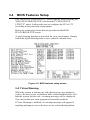
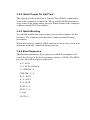
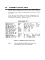
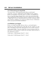
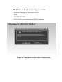
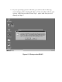
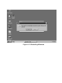
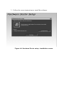
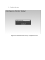
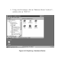
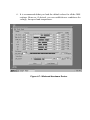
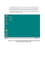
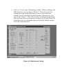
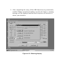
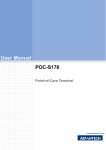
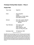
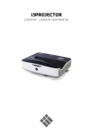
User’s Manual Insert for PCA-6175 Pentium® II processorbased PCI/ISA-bus CPU card Users Manual Please note the following changes to the PCA-6175 User’s Manual, 1st edition, published May 1998. These changes relate to on-board security features of the card. The main sections in the manual affected are: Initial inspection (in the front section) Page v in the published manual is to be replaced by “Initial inspection” in this insert. Award BIOS Setup Section 3.4 in the published manual is to be replaced by Section 3.4 in this insert. Chipset Features Setup Section 3.5 in the published manual is to be replaced by Section 3.5 in this insert. A new Chapter 4, On-board Security Setup, is now also included. Part No. 2006617502 Initial inspection Before you begin installing your card, please make sure that the following materials have been shipped: • 1 PCA-6175 Pentium® II single board computer • 1 Pentium II CPU and cooling fan (optional) • 1 PCA-6175 user's manual • 1 bus master & BIOS utility driver • 2 disks, for OBS Win95 drivers • 1 FDD cable • 2 EIDE HDD cables • 1 printer cable • 1 temperature sensor cable • 1 ivory cable for keyboard and mouse • 1 ATX-to-PS/2 power cable • 1 Pentium II CPU retention module If any of these items are missing or damaged, contact your distributor or sales representative immediately. We have carefully inspected the PCA-6175 mechanically and electrically before shipment. It should be free of marks and scratches and in perfect working order upon receipt. As you unpack the PCA-6175, check it for signs of shipping damage. (For example, damaged box, scratches, dents, etc.) If it is damaged or it fails to meet the specifications, notify our service department or your local sales representative immediately. Also notify the carrier. Retain the shipping carton and packing material for inspection by the carrier. After inspection, we will make arrangements to repair or replace the unit. 3.4 BIOS Features Setup The “BIOS FEATURES SETUP” screen appears when choosing the "BIOS FEATURES SETUP" item from the "CMOS SETUP UTILITY" menu. It allows the user to configure the PCA-6175 according to his particular requirements. Below are some major items that are provided in the BIOS FEATURES SETUP screen. A quick booting function is provided for your convenience. Simply enable the Quick Booting item to save yourself valuable time. Figure 3-2: BIOS features setup screen 3.4.1 Virus Warning While the system is booting up, and after boot-up, any attempt to write to the boot sector or partition table of the hard disk drive will halt the system. In this case, a warning message will be displayed. You can run the anti-virus program to locate the problem. If Virus Warning is disabled, no warning message will appear if anything attempts to access the boot sector or hard disk partition. 3.4.2 Quick Power On Self Test This option speeds up the Power-On Self Test (POST) conducted as soon as the computer is turned on. When enabled, BIOS shortens or skips some of the items during the test. When disabled, the computer conducts normal POST procedures. 3.4.3 Quick Booting You should disable this option when you boot the computer for the first time. The computer will thereafter conduct normal booting procedures. When this option is enabled, BIOS shortens or skips some of the tests and items normally conducted during boot-up. 3.4.4 Boot Sequence This function determines the sequence in which the computer will search the drives for the disk operating system (i.e. DOS). The BIOS provides the folllowing boot sequences: A,C, SCSI C,A. SCSI (Default) C, CDROM, A CDROM, C, A D, A, SCSI E, A, SCSI F, A, SCSI SCSI, A, C SCSI, C, A C only LS120, C 3.4.5 Boot Up Floppy Seek During POST, BIOS will determine if the floppy disk drive installed is 40 or 80 tracks. A 360 KB type drive is 40 tracks; while 720 KB, 1.2 MB, and 1.44 MB type drives are all 80 tracks. Enabled BIOS searches the floppy drive to determine if it is 40 or 80 tracks. Note that BIOS cannot differentiate 720 KB, 1.2 MB, and 1.44 MB type drives as they are all 80 tracks. Disabled BIOS will not search for the floppy drive type by track number. Note that there will not be any warning message if the drive installed is 360 KB. 3.4.6 Boot Up NumLock Status The default is “On”. On Keypad boots up to number keys. Off Keypad boots up to arrow keys. 3.4.7 Boot Up System Speed High Sets the speed to high. Low Sets the speed to low. 3.4.8 IDE HDD Block Mode Enabled Enable IDE HDD Block Mode. BIOS will detect the block size of the HDD and send a block command automatically. Disabled Disable IDE HDD Block Mode. 3.4.9 Gate A20 Option Normal The A20 signal is controlled by the keyboard controller or chipset hardware. Fast (Default) The A20 signal is controlled by Port 92 or the chipset specific method. 3.4.10 Typematic Rate Setting The typematic rate determines the characters per second accepted by the computer. The Typematic Rate setting enables or disables the typematic rate. 3.4.11 Typematic Rate (Chars/Sec) BIOS accepts the following input values (characters/second) for typematic rate: 6, 8, 10, 12, 15, 20, 24, 30. 3.4.12 Typematic Delay (msec) Typematic delay is the time interval between the appearance of the first and second characters, when holding down a key. The input values for this category are: 250, 500, 750, 1000 (msec). 3.4.13 Security Option This setting determines whether the system will boot up if the password is denied. Access to Setup is, however, always limited. System The system will not boot, and access to Setup will be denied if the correct password is not entered at the prompt. Setup The system will boot, but access to Setup will be denied if the correct password is not entered at the prompt. Note: To disable security, select "PASSWORD SETTING" in the main menu. At this point, you will be asked to enter a password. Simply press <Enter> to disable security. When security is disabled, the system will boot, and you can enter Setup freely. 3.4.14 OS Select for DRAM > 64 MB This setting is under the OS/2 system. 3.4.15 Video BIOS Shadow This determines whether video BIOS will be copied to RAM, which is optional according to the chipset design. When enabled, Video BIOS Shadow increases the video speed. 3.4.16 C8000-CBFFF Shadow / DC000-DFFFF Shadow These determine whether optional ROM will be copied to RAM in blocks of 16 KB. Enabled Optional shadow is enabled. Disabled Optional shadow is disabled. 3.5 CHIPSET Features Setup By choosing the “CHIPSET FEATURES SETUP” option from the INITIAL SETUP SCREEN menu, the screen below will be displayed. This sample screen contains the manufacturer’s default values for the PCA-6175. If you enable the OBS function, you can view the temperature, fan speed and voltage of your PC system. The data will be displayed in similar fashion to the display shown in Fig. 3-3: Figure 3-3: CHIPSET features setup screen Note: If you enable the IDE HDD block mode, the enhanced IDE driver will be enabled. CHAPTER 4 On-board Security Setup This chapter explains OBS concepts and provides instructions for installing the relevant software drivers. This is done using the OBS driver disks included in your PCA-6175 package. 4.1 Introduction On-board security (OBS) functions monitor key hardware. They help you maintain your system's stability and durability. The PCA-6175 can monitor 5 sets of system positive voltages, 2 sets of system negative voltages, CPU cooling fan speed, and CPU temperature. The positive system voltage sets which can be monitored include: • CPU core voltage: 1.7 V ~ 3.3 V, according to Intel specifications • Transmission voltage from CPU to chipset: typically 1.5 V • Chipset voltage: typically 3.3 V • Main voltage: +5 V, +12 V The negative system voltage sets which can be monitored include: • Main voltage: -5 V, -12 V 4.2 Installation of OBS Devices After you have mounted the CPU and cooling modules, enable the OBS functions as follows: 1. Take the specially designed temperature sensor cable out of the accessories bag. 2. Connect the 2-pin header of the cable to connector RT1. 3. Attach the sticker to the heat sink, but NOT on the plastic portion of the heat sink. 4. Place the sensor on the nearest part of the CPU, to ensure that true CPU temperature is measured. 4.3 Driver Installation 4.3.1 Necessary prerequisites The instructions in this manual assume that you understand elementary concepts of MS-DOS and the IBM personal computer. Before you attempt to install any driver or utility, you should know how to copy files from a floppy disk to a directory on the hard disk; understand the MS-DOS directory structure; and know how to format a floppy disk. If you are uncertain about any of these concepts, please refer to DOS or Windows user reference guides for more information before you proceed with the installation. 4.3.2 Before you begin Before you begin installing software drivers, you should make a backup copy of the display driver disk and store the original in a safe place. The display driver disk contains drivers for several versions of certain applications. You must install the correct version in order for the driver to work properly, so make sure you know which version of the application you have. Utility disk 1: OBS Monitor Win95 V 1.00 #1 Utility disk 2: OBS Monitor Win95 V 1.00 #2 4.3.3 Windows 95 drivers setup procedure 1. Insert the OBS driver disk into drive A:. Type: A:\setup.exe Press <Enter> to run the driver SETUP program. Figure 4-1: Hardware Doctor setup - initial screen 2. If your operating system is Win95, you will see the following screen images after running the driver. You must then reboot your system, start the procedure from Step 1 again, and then proceed directly to Step 3. Figure 4-2: Setup under Win95 Figure 4-3: Restarting Windows 3. Follow the screen instructions to install the software. Figure 4-4: Hardware Doctor setup - installation screen 4. Complete the setup. Figure 4-5: Hardware Doctor setup - completion screen 5. Using your file manager, click on "Hardware Doctor" in drive C:, and then click on "W83781". Figure 4-6: Exploring - Hardware Doctor 6. It is recommended that you load the default values for all the OBS settings. However, if desired, you can establish new conditions for voltage, fan speed and temperature. Figure 4-7: Winbond Hardware Doctor 7. "Winbond Hardware Doctor" will show an icon on the right side of the bottom window bar. This icon is the "Terminate and Stay Resident" (TSR) icon. It will permanently remain in the bottom window bar, and will activate warning signals when triggered by the on-board security system. Figure 4-8: "Terminate and Stay Resident" (TSR) icon on the right side of the bottom window bar 8. Click on "Tools", then "Monitoring Config." While enabling each OBS function, you can choose "Faults 1". This will result in a warning message being delivered as soon as any monitored reading exceeds safe limits for the first time. Alternatively, you can set up "Count 3". This will result in a warning message being delivered only after any monitored reading exceeds safe limits for a third time. It is recommended that you load the default settings for all the OBS functions. Figure 4-9: Monitoring Config. 9. After completing the setup, all the OBS functions are permanently enabled. When a monitored reading exceeds safe limits, a warning message will be displayed and an error beep tone will activate to attract your attention. Figure 4-10: Warning display