1
Restarts for autonumbers that do not restart in each
chapter.
figure bi level 1, reset
table_big level 1, reset
chap_big level 1, reset
app_big level 1, reset
figure_ap level 1, reset
table_ap level 1, reset
figure level 1, reset
table level 1, reset
these restarts must be in the header frame of chapter 1.
a:ebx, l 1 resetA
a:obx:l 1, resetA
a:bigbx level 1 resetA
a:ftr level 1 resetA
c:ebx, l 1 reset1
c:obx:l 1, reset1
c:bigbx level 1 reset1
c:ftr level 1 reset1
Reminders for autonumbers that need to be restarted
manually (first instance will always be 4)
let_in level 1: A. B. C.
letter level 1:A.B.C.
num level 1: 1. 2. 3.
num_in level 1: 1. 2. 3.
rom_in level 1: I. II. III.
roman level 1: I. II. III.
steps level 1: 1. 2. 3.
October 1, 1997
GFK-1314E
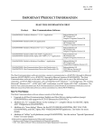
IMPORTANT PRODUCT INFORMATION
READ THIS INFORMATION FIRST
Product:
Factory LAN TCP/IP Ethernet Interface (Type 2)
IC697CMM742-FD Firmware Version 2.00
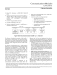
This is release 2.00 of the IC697 Ethernet Interface Module (Type 2). This module
provides network communications using SRTP (Service Request Transfer Protocol) over
standard TCP/IP (Transmission Control Protocol and Internet Protocol) on an Ethernet
LAN (Local Area Network). The Ethernet Interface supports communications between
IC697 PLCs and/or IC693 PLCs equipped with TCP/IP Ethernet Interfaces. The Ethernet
Interface can also communicate with IC641 TCP/IP Ethernet programming software and
applications which use the TCP/IP Host Communication Toolkit software.
Additional features and benefits for this module include:
H
Higher performance compared to IC697CMM741—2 to 4 times higher throughput
for data transfers between PLCs with identical Channel setups.
H
H
32 simultaneous network connections—twice the number supported by IC697CMM741.
H
Addressability to other IC697CMM742 Interfaces using DDP names, standard DNS
(Domain Name Service) names, or IP addresses.
H
Three alternate Ethernet network ports are available on the IC697CMM742
Interface. Two of the network ports, the 10BaseT (twisted pair) and the 10Base2
(thin wire), require no external transceiver. In addition, a standard AUI port is
available for use with an external user-supplied transceiver. Only one of the three
network ports may be used at a time.
Configuration of Ethernet Interface fully supported within CPU configuration.
Centralized IP network configuration management is also supported via standard
BOOTP protocol.
Release 2.00 provides additional features and benefits for this module. All new features
require IC641 Configuration Software Version 2.00. The features include Ethernet
Global Data and Enhanced Name Resolution support. A description of these features is
provided later in this document.
Compatibility
The IC697CMM742 Ethernet Interface is compatible with the following products:
H
IC697 PLC CPU models 781, 782, 914, 915, 924, and 925 loaded with firmware
versions 6.00 or later. Limited Server-mode only operation is possible with older CPU
models (described below). CPU Release 7.0 or higher is required for Ethernet Global
Data and Enhanced Name Resolution.
H
IC641 programming software version 6.02 or later (required to configure the
Ethernet Interface).
H
H
IC697CMM741 Ethernet Interface loaded with TCP/IP software IC651ENS042.
IC693CMM321 Ethernet Interface.
Important Product Information: Factory LAN TCP/IP Ethernet Interface (Type 2)
2
GFK-1314E
October 1, 1997
H
Host Communications Toolkit software products, listed below.[
h
h
h
h
h
h
Toolkit for MicrosoftR WindowsR C/C++ Applications (IC641SWP052D or later)
Toolkit for Windows NT C/C++ Applications (IC641SWP058B or later)
Toolkit for HP-UX C Applications (IC641SWP054B or later)
Toolkit for DECt VAX/VMS C Applications (IC641SWP053B or later)
Toolkit for DEC Alpha AXP/VMS C/C++ Application (IC641SWP057B or later)
Host Communication Drivers for Windows
(qty.1: IC641SWP050D; qty.10 - IC641SWP051D)
Product Documentation
TCP/IP Ethernet Communications (Type 2) for the IC697 PLC User’s Manual, GFK-1246.
TCP/IP Ethernet Communications for the IC69* Station Manager Manual, GFK-1186.
New Features
Ethernet Global Data
Ethernet Global Data is a mechanism by which one device, referred to as a producer, can
share a portion of its internal memory with one or more other devices, referred to as
consumers, at a regularly scheduled periodic rate. The snapshot of internal memory is
referred to as an exchange. This exchange is uniquely distinguished by a set of identifiers,
the Producer ID and Exchange ID. The Producer ID is assigned to uniquely identify the
Ethernet Global Data device on the network (or ‘routed’ networks). The Exchange ID is
a value identifying a specific exchange definition within that producing device. An
in–depth description of this feature is available through the Online Help system of the
configuration software. Use of this feature requires IC697 CPU Release 7.00 or later as
well as IC641 Configuration software Version 2.00 or later.
Enhanced Name Resolution
This release of firmware extends the Naming Resolution capabilities to allow
configuration of naming parameters via IC641 Configuration Software Version 2.0.
These parameters include the Network Address Name and the Name Table. Previous
versions of IC697CMM742 firmware restricted naming parameter configuration to
station manager commands while in maintenance mode.
Reduction in Fault Logging for Event 12, entry 2 = f
This fault is logged upon receipt of a TCP Reset. Previously released versions of
IC697CMM742 firmware would log this condition regardless of the state of the TCP
connection. This release of firmware will only log this condition if the connection has
not been successfully established. This is to accommodate certain host TCP/IP stacks that
routinely terminate connections using TCP Reset (instead of TCP FIN).
{
r
t
Some versions of HCT do not support the “Send Information Report” COMMREQ.
Please refer to the appropriate HCT IPI document for more information.
Microsoft and Windows are registered trademarks of Microsfot Corporation.
DEC. VAX, Alpha AXP, and VMS are trademarks of Digital Equipment Corporation.
3
Important Product Information: Factory LAN TCP/IP Ethernet Interface (Type 2)
GFK-1314E
October 1, 1997
LLC Recovery Time Reduced
Whenever a fatal LLC error is encountered (recorded as log event c, entry 2 = 105, 10a,
10b, or 10f) the Ethernet controller on the Ethernet Interface is reinitialized. Previously
released versions of IC697CMM742 firmware would retry immediately and then wait 10
seconds before attempting recovery. This release of firmware will now attempt recovery
immediately and then once a second for the first 10 seconds, then once every 10 seconds
as before.
Increased Queue Sizes
Due to available memory on the IC697CMM742, various queue sizes have been
increased to avoid potential network packet discards. These include the LLC receive
ring (increased from 64 to 128) and the IP layer input queue (increased from 64 to 128)
and the IP layer output queue (increased from 33 to 128).
Enhanced Problem Debugging Tools
Various enhancements have been made in this release of firmware to provide better
debugging tools. They include:
Additional Information in Fault Logging for Event 12, entry 2 = 10–1C – TCP Log
events (Event 12) that recorded the taking down of a TCP connection did not identify
the remote host that was connected. This information can be useful for system
troubleshooting and was often impossible to get after the connection came down. TCP
log events, entry 2=10 through 1c have now been updated to show the IP address of the
remote node in entries 3 and 4.
New Station Manager Command: “killss” – The new “killss” station manager
command has been added in this release of the IC697CMM742 TCP/IP firmware. The
“killss” command is used to terminate established SRTP Server endpoints. This
command is intended for maintenance and diagnostic purposes only. The syntax for the
command is as follows:
killss all|<SRTP Server endpoint> [<SRTP Server endpoint> [...]]
‘killss all’ causes all established SRTP Server endpoints to be terminated. If the
endpoint numbers (as shown in the output of ‘stat v’ command) are specified, only
those endpoints would be terminated. This command will not terminate any endpoints
which are not in ESTABLISHED state.
The “killss” command is a modify command; therefore, the user is required to be logged in
before using this command.
Enhanced Station Manager Output for “stat v” – To help in debugging a PLC setup,
the number of received requests and the IP address of the client for every SRTP Server
endpoint have been added to the display in response to “stat v” station manager
command.
Important Product Information: Factory LAN TCP/IP Ethernet Interface (Type 2)
4
GFK-1314E
October 1, 1997
Operational Notes
Network Bandwidth Utilization
Due to its performance potential, the IC697CMM742 Interface can present a heavy load
on the network segment at its maximum operating capacity. It is strongly recommended
that caution be taken when using multiple connections operating in an “as fast as possible”
mode. Tests conducted showed that 32 simultaneous Channels transferring 2 Kilobytes
of data per Channel between two IC697CMM742 Interfaces can use up as much as 18%
of the total network bandwidth when the Channels are all configured to run “as fast as
possible” using 91x or 92x CPUs.
The potentially high network bandwidth utilization by the IC697CMM742 Interface can
cause higher-than-normal rate of network collisions which may cause timeouts on data
transfers. If your application requires many simultaneous network connections between
IC697CMM742 Interfaces, it is recommended that the “minimum interval between host
accesses”, “read period”, and “write period” used in COMMREQs be set to the required rate
for your particular application instead of “as fast as possible” so the network does not
become overloaded with network traffic to and from the IC697CMM742 Interface.
CPU Performance Limitation
Again, due to its performance potential, the IC697CMM742 Interface can present a
heavy load on the CPU at its maximum operating capacity. It is strongly recommended
that caution be taken when using multiple connections operating in an “as fast as
possible’”mode especially when a model 781 or 782 CPU is used. The COMMREQ Status
Word (CRS Word) may occasionally become FE07 or FE87, which means service requests
are made to the CPU faster than the CPU can process them. Although communications
will proceed to the next repetition even when this is encountered, data transfer for the
current repetition of this connection would have failed to complete.
To avoid this situation, configure the “minimum interval between host accesses”, “read period”,
or “write period” to a larger value so the CPU has enough time to process all service
requests.
Channel Data Transfer with One Repetition can
Exhaust TCP Connections
Because tearing down a TCP connection is time consuming, it is possible that
programming your ladder in a certain way can quickly exhaust all available TCP
connections. This can be avoided by programming your COMMREQs in a slightly
different way.
Your ladder can benefit from the reprogramming if:
H
The number of repetitions (word 9 in an Establish Read Channel or Establish Write
Channel COMMREQ) is set to one (1) and a new COMMREQ is issued immediately
upon completion of the prior one.
H
H
Each successive COMMREQ is directed to the same target device (same IP address).
Each successive COMMREQ is directed to the same channel number.
To avoid TCP connection exhaustion you should set the number of repetitions
(COMMREQ word 9) to two (2) and set the read/write period (COMMREQ words 10
Important Product Information: Factory LAN TCP/IP Ethernet Interface (Type 2)
GFK-1314E
5
October 1, 1997
and 11) to be very large, such as 60 seconds. With these parameters you can issue the
first COMMREQ, wait for the COMMREQ Status (CRS) word to turn to one (1), then
issue the next COMMREQ, wait for the CRS word to turn to one, etc., and there will not
be TCP connection exhaustion problems. Interrupting an active channel allows the reuse
of an existing TCP connection, while a repetition count of one starts the time-consuming
TCP connection teardown immediately upon completion of the first transfer.
Special Notes on Release 6 CPUs
When your ladder program accesses %P and %L memories through COMMREQs, and a
Release 6 CPU is used on the server PLC, the COMMREQ Status Word (CRS Word) may
occasionally return F405.
AUI Cable Removal
Power to the PLC must be turned off whenever the transceiver cable (AUI cable) is
connected or disconnected at the IC697CMM742 Interface AUI port.
Ethernet Interface PLC Installation Restrictions
The IC697CMM742 Interface may not be used in an IC697 PLC expansion rack. The
Ethernet Interface will not function properly if placed there.
There may be no more than four (4) LAN Interfaces in a single PLC. This limit applies to
the total number of IC697CMM721, IC697CMM731, IC697CMM741, and IC697CMM742
boards in the PLC.
Some PLC Fault Table Entries are Imprecise
In the PLC Fault Table display of the IC641 Programming software, the following
messages may not provide a meaningful description of the problem for the Ethernet
Interface:
H
H
H
“LAN PROM/software mismatch; running soft Sw util”
“LAN system-software fault; resuming”
“LAN Severe Network Problem; Attempting Recovery”
Should you see these messages in the IC641 software, select the message and enter F10
(ZOOM) or CTRL+F to display the error codes associated with the message. Then refer
to GFK-1186A, Appendix B: “Exception Log Event Description” for an accurate explanation
of the error codes.
SQE Enable
If the AUI network port is used, the IC697CMM742 Interface requires that the SQE test
be enabled on the external transceiver connecting it to the Ethernet LAN. Make sure
your transceiver has SQE enabled.
PLC Power Supply Requirements
If the AUI network port is used, the IC697CMM742 Interface requires that the PLC
include a power supply which supplies 12Vdc (IC697PWR711, -721, -724, -731, or -748).
Important Product Information: Factory LAN TCP/IP Ethernet Interface (Type 2)
6
GFK-1314E
October 1, 1997
Restrictions and Significant Open Problems
Open Problems in Release 2.00 Firmware
This section describes known limitations in the current firmware, Release 2.00.
ÁÁÁÁÁÁÁÁÁÁÁÁÁÁÁÁÁÁÁÁÁÁÁÁÁÁÁÁÁÁÁÁÁ
ÁÁ
ÁÁÁÁÁ
ÁÁ
ÁÁÁÁÁÁÁÁÁÁÁÁÁÁÁÁÁÁÁÁÁÁÁÁ
ÁÁÁÁÁÁÁÁÁÁÁÁÁÁÁÁÁÁÁÁÁÁÁÁ
ÁÁ
ÁÁÁÁÁ
ÁÁ
ÁÁÁÁÁ
ÁÁÁÁÁÁÁÁÁÁÁÁÁÁÁÁÁÁÁÁÁÁÁÁ
ÁÁ
ÁÁ
ÁÁÁÁÁÁÁÁÁÁÁÁÁÁÁÁÁÁÁÁÁÁÁÁÁÁÁÁÁÁÁ
ÁÁ
ÁÁÁÁÁÁÁÁÁÁÁÁÁÁÁÁÁÁÁÁÁÁÁÁ
ÁÁ
ÁÁÁÁÁ
ÁÁ
ÁÁÁÁÁ
ÁÁÁÁÁÁÁÁÁÁÁÁÁÁÁÁÁÁÁÁÁÁÁÁ
ÁÁ
ÁÁ
ÁÁÁÁÁÁÁÁÁÁÁÁÁÁÁÁÁÁÁÁÁÁÁÁ
ÁÁÁÁÁÁÁ
ÁÁ
ÁÁÁÁÁÁÁÁÁÁÁÁÁÁÁÁÁÁÁÁÁÁÁÁÁÁÁÁÁÁÁ
ÁÁ
ÁÁ
ÁÁÁÁÁ
ÁÁ
ÁÁÁÁÁÁÁÁÁÁÁÁÁÁÁÁÁÁÁÁÁÁÁÁ
ÁÁ
ÁÁÁÁÁ
ÁÁ
ÁÁÁÁÁÁÁÁÁÁÁÁÁÁÁÁÁÁÁÁÁÁÁÁ
ÁÁ
ÁÁ
ÁÁÁÁÁÁÁÁÁÁÁÁÁÁÁÁÁÁÁÁÁÁÁÁ
ÁÁÁÁÁ
ÁÁ
ÁÁÁÁÁ
ÁÁ
ÁÁÁÁÁÁÁÁÁÁÁÁÁÁÁÁÁÁÁÁÁÁÁÁ
ÁÁÁÁÁÁÁÁÁÁÁÁÁÁÁÁÁÁÁÁÁÁÁÁÁÁÁÁÁÁÁÁÁ
ID Code
54556
Description
The IC697CMM742 Interface can not communicate with the local PLC CPU when a PLC
load or a store operation is in progress. A PLC load or store operation (via IC641 software
WSI, Serial, and/or Ethernet) has priority over all other communications. During a PLC
load or store operation, it is possible for channels or server connections to experience time
out errors, which may lead to disconnections.
Possible exception log entries include 8/8, 8/38, and 8/40. Whenever these backplane errors
are logged, there are likely to also be additional exception logs for terminated TCP connections and SRTP Server and Channel API errors.
60873
Log Event c, entry 2 = 10f has been witnessed during extremely heavy traffic conditions on
the Local Area Network. A potential workaround is to increase the size of the LLC transmit
ring. The current value is 3, implying a ring size of 8. A value of 4 specifies a transmit ring
size of 16, value 5 specifies a ring size of 32. This value can be changed in the IC697CMM742
Maintenance mode using the station manager ‘chparm ltxringlen’ command.
Changes and Additions to the User’s Manual (GFK-1246)
Instructions for Upgrading Firmware
These instructions are provided in Appendix E of the User’s Manual.
Special Notes on Using IC697CMM742 with PLC CPUs (Versions 4.12 - 5.50)
The IC697CMM742 Ethernet Interface (Type 2) is designed for high-performance
operation and convenient installation with IC697 PLC CPU versions 6.00 and later. These
PLC CPUs recognize and support the Ethernet Interface (Type 2), and provide the high
throughput demanded by this product. GE Fanuc recommends use of IC697 PLC CPUs
with version 6.00 and later firmware to obtain the full capabilities of the Ethernet
Interface (Type 2).
Versions 1.10 and later of the Ethernet Interface (Type 2) also provide restricted
operation with IC697 PLC CPUs running firmware versions 4.12 through 5.50. These
notes describe the necessary Ethernet Interface configuration and restricted operation
with these PLC CPUs.
The Ethernet Interface (Type 2) cannot be used with PLC CPU firmware versions prior
to 4.12.
7
Important Product Information: Factory LAN TCP/IP Ethernet Interface (Type 2)
GFK-1314E
October 1, 1997
Ethernet Interface Installation and Configuration
The Ethernet Interface (Type 2) is installed in the main PLC rack as described in
Procedure 1 in Chapter 2 of the TCP/IP Ethernet (Type 2) Users Manual.
IC697 PLC CPU firmware versions 4.12 though 5.50 do not accept PLC configuration
data for the Ethernet Interface (Type 2). Thus this Ethernet Interface cannot be
configured as described in Procedure 2 in Chapter 2 of the User’s Manual. An alternate
Procedure 2 is provided below; this procedure uses a user-supplied computer terminal
or equivalent plus the Station Manager software within the Ethernet Interface to enter
the necessary configuration data. The Station Manager is completely described in the
TCP/IP Ethernet Station Manager Manual. Please refer to this manual for complete details
on connecting a terminal to the Station Manager serial port of the Ethernet Interface,
and on the various Station Manager commands used within this alternate Procedure 2.
Alternate Procedure 2: Configuring the Ethernet Interface
(with PLC CPU versions 4.12 through 5.50)
IC697 PLC CPU firmware versions prior to version 6.00 do not accept configuration data
for the Ethernet Interface (Type 2). Thus the Ethernet Interface (Type 2) cannot be
configured by the IC641 PLC Configuration software. Instead, a dummy module must
be configured in place of the Ethernet Interface; the Station Manager software within
the Ethernet Interface is then used to enter configuration data directly at the module.
First, create a dummy entry in the PLC Configuration for the rack and slot where the
Ethernet Interface is installed.
1.
Connect a PC running the IC641 PLC Configuration software to the PLC via the
built-in serial port on the PLC CPU module. Then access the I/O Configuration
screen of the IC641 PLC Configuration software.
2.
Move the cursor to the rack and slot where the Ethernet Interface (Type 2) is
installed. This slot must be configured as a “3rd Party VME module” as follows:
From the I/O Configuration screen, press the vme soft key (F7). From the next
screen, press the vme soft key (F1), then move the cursor to the 3RD PARTY VME
MODULE selection and press the Enter key to select. Press the Escape key to
return to the I/O Configuration screen. The slot containing the Ethernet Interface
will be displayed as “3PY VME”.
If there is no vme soft key in the I/O Configuration screen, configure the rack and
slot where the Ethernet Interface (Type 2) is installed as a “Blank jumper” as follows:
Press the m70_io soft key (F1). From the next screen, press the other soft key
(F7), then move the cursor to the BLANK SLOT INTERRUPT JUMPER selection
and press the Enter key to select. Press the Escape key to return to the I/O
Configuration screen. The slot containing the Ethernet Interface will be displayed as
“JUMPER”.
3.
Press the Escape key to save the PLC configuration to disk.
4.
Use of the dummy module type above will always result in a Configuration
Mismatch error at each power up, configuration store, or Ethernet Interface restart.
To prevent this error from putting the PLC into STOP/FAULT state, change the
severity of this error as follows:
Important Product Information: Factory LAN TCP/IP Ethernet Interface (Type 2)
8
GFK-1314E
October 1, 1997
From the main PLC Configurator screen, press the cpu soft key (F2) to display the
CPU configuration, then press the fltcfg key (F5) to display the Fault
Categories. Press the down arrow key () repeatedly until Fault Type is
“System Config Mismatch”, then press the Tab key to change the Fault
Category from “F” (= Fatal) to “D” (= Diagnostic). Press the Escape key twice to
store the fault categories to the PLC CPU and return to the main PLC Configurator
screen
5.
Store the PLC configuration to the PLC.
Now configure the Ethernet Interface (Type 2) locally using its onboard Station
Manager. Refer to the TCP/IP Ethernet Station Manager Manual for complete
information on Station Manager operation.
6.
Connect a standard ASCII terminal or PC-based terminal emulator to the Station
Manager (RS-232) serial port on the Ethernet Interface. Use the NODE Station
Manager command to verify that the terminal or emulator is properly
communicating with the Station Manager software in the Ethernet Interface. A
typical NODE command is shown below:
> node
IC697 PLC Factory LAN Ethernet Interface (Type 2)
Copyright (c) 1996. All rights reserved.
Version 1.10 (25A1) TCP/IP
Version 1.00 (12A1) Software Loader
IP Address = 0.0.0.0
MAC Address = 080019010688
*** PLC CPU version (5.00) supports restricted LAN Interface operation:
***
SRTP server only (client operation is not permitted)
***
LAN Interface cannot be configured with PLC Configurator
***
(Use CHSOSW Station Manager cmd to enter module configuration)
***
PLC CPU version 6.00 or higher is required for full operation
If the Ethernet Interface has not been previously configured, the NODE output will
also indicate that the Ethernet Interface is waiting for a valid IP address.
7.
Use the LOGIN Station Manager command to “log in” in order to access the
Modify-level commands needed later. The LOGIN command is shown below:
> login
After entering the LOGIN command, the Station Manager prompts for the
Modify-level password:
Password:
Enter your password (which is not echoed). The default password is: system
(lower case). If the password matches the current Modify-level password, a
confirmation message is displayed; the Station Manager prompt changes from “>” to
“=”.
8.
Use the Modify-level MAINT Station Manager command to restart the Ethernet
Interface into the Maintenance state. The MAINT command is shown below:
= maint
Restarting module into Maintenance state
Important Product Information: Factory LAN TCP/IP Ethernet Interface (Type 2)
GFK-1314E
9
October 1, 1997
The Ethernet Interface is restarted into the Maintenance state. After approximately
20 seconds, another NODE output is automatically generated when the restart is
complete. The display will also indicate that the Ethernet Interface is the
Maintenance state; the Station Manager prompt is “*”. Modify-level login is not
required in the Maintenance state.
9.
Use the CHSOSW Station Manager commands to enter the configuration data for
this Ethernet Interface. The IP addressing parameters ( ip_address, subnet_mask,
gateway, and name_server) must be set to values supplied by the person in charge of
your network ( the network administrator). TCP/IP network administrators are
familiar with these parameters. It is important that these parameters are correct,
otherwise the Ethernet Interface may be unable to communicate on the network
and/or network operation may be corrupted. It is especially important that each
node on the network is assigned a unique IP address.
Enter the IP Address as follows:
* chsosw ip_address <a.b.c.d>
where <a.b.c.d> is the unique dotted decimal IP address for this node.
Enter the Subnet Mask as follows
* chsosw subnet_mask <a.b.c.d>
where <a.b.c.d> is the dotted decimal subnet mask for this network segment.
Enter the Gateway IP Address as follows
* chsosw gateway <a.b.c.d>
where <a.b.c.d> is the unique dotted decimal IP address of the gateway device.
Enter the Name Server IP Address as follows:
* chsosw name_server <a.b.c.d>
where <a.b.c.d> is the unique dotted decimal IP address of the name server device.
The CHSOSW command may also be used to change the parameters for either serial
port on the Ethernet Interface in cases where the default serial port configuration
values are not used.
Refer to the TCP/IP Ethernet Station Manager Manual for further information.
A typical CHSOSW command is shown below:
* chsosw ip_address 3.0.0.1
Once entered, the configuration parameters are retained in non-volatile flash
memory for use each time the Ethernet Interface is powered up or restarted.
Configuration needs to be re-entered only when changing one or more
configuration parameters.
Important Product Information: Factory LAN TCP/IP Ethernet Interface (Type 2)
10
GFK-1314E
October 1, 1997
10. Use the SOSW Station Manager command to verify that all configuration
parameters have been set to the proper values. A typical SOSW command is shown
below:
* sosw
<<< Soft Switch Data >>>
IP Address
Subnet Mask
Gateway
Name Server
=
=
=
=
3.0.0.1
0.0.0.0
0.0.0.0
0.0.0.0
Port 1 (Station Manager):
Data Rate
= 9600
Parity
= NONE
Stop Bits
= 1
Flow Control
= NONE
TurnA Delay
= NONE
Timeout
= LONG
(TCP/IP values from Soft Switches)
Port 2 (S/W Loader):
Data Rate
= 19200
Parity
= ODD
Stop Bits
= 1
Flow Control = NONE
TurnA Delay
= NONE
Timeout
= LONG
Source of Soft Switches: Internal Backup
11. When all configuration parameters have been correctly entered, use the RESTART
Station Manager command to restart the Ethernet Interface into normal operation.
The RESTART command is shown below:
= restart
Restarting module
The Ethernet Interface is restarted into the Operational state. After approximately 20
seconds, another NODE output is automatically generated when the restart is
complete. The NODE output should indicate the IP Address configured in Step 9,
above. (The Subnet Mask, Gateway IP Address and Name Server IP Address can be
displayed by the SOSW command, as described in Step 10, above.) The Ethernet
Interface is now properly configured and ready for use.
Please proceed to Procedure 3 in Chapter 2 of the User’s Manual to verify proper
operation of the Ethernet Interface with the new configuration data.
Ethernet Interface Operational Restrictions
The Ethernet Interface (Type 2) operates with some restrictions when used with IC697
PLC CPU versions 4.12 through 5.50. These Operational Restrictions, together with
differences in Startup, Station Manager and Software Loader operation, are described
below.
Operational Restrictions
1.
COMMREQ operation is not supported. Any COMMREQ issued to the Ethernet
Interface is ignored; a COMMREQ Status (CRS) word is not returned to the PLC.
Instead, the Ethernet Interface generates an event in its internal exception log
(Event = 1c; Entry 2 = 0011) indicating that the Channel API task is not active. The
Ethernet Interface also generates an entry in the PLC Fault Table:
(“LAN system-software fault; resuming”)
Important Product Information: Factory LAN TCP/IP Ethernet Interface (Type 2)
GFK-1314E
2.
3.
October 1, 1997
The Ethernet Interface returns neither LAN Interface Status (LIS) nor Channel
Status data to the PLC.
PLC CPU models IC697CPU73x and IC697CPU77x may limit the overall
performance of a PLC used as a server device. Under heavy load from other clients
and hosts on the network, the server PLC may generate errors with major error
code 07, indicating that the volume of requests from the network have exceeded the
processing capacity of the PLC CPU. If possible, try to reduce the volume of requests
to the server PLC when this condition occurs. If the system design requires data
rates beyond the capacity of the server PLC CPU, please consider upgrading to a
more powerful CPU model.
Startup
1.
11
Upon each powerup or restart of the Ethernet Interface, or configuration store to the
PLC, the following entry will be generated in the PLC Fault Table for the slot
containing the Ethernet Interface:
(“Reset of, addition of, or extra option module”).
2.
When operating with PLC CPU versions prior to 6.00, the Ethernet Interface does
not generate the exceptions or PLC Faults that normally occur when Ethernet
Interface does not receive module configuration from the PLC CPU.
3.
Each powerup and restart of the Ethernet Interface takes approximately 20 seconds.
This is roughly 10 seconds longer than required when the Ethernet Interface is used
with PLC CPU versions 6.00 and later.
Station Manager
1.
.The STAT C command (PLC Driver status) does not display the current PLC CPU
state (RUN/STOP and I/O ENABLED/ I/O DISABLED).
2.
In the TALLY C command output (PLC Driver tallies), the “PlcSweep” tally does not
count the number of PLC sweeps. This tally should be ignored.
3.
The STAT H command (Channel API status) always indicates “Channel API
task not initialized”
4.
As detailed above in the Ethernet Interface Installation and Configuration section, special
restricted operation notification is displayed with the startup message and by the
NODE command.
Important Product Information: Factory LAN TCP/IP Ethernet Interface (Type 2)
12
GFK-1314E
October 1, 1997
Software Loader
IC697 PLC CPU versions 6.00 and later gracefully allow option modules like the Ethernet
Interface to suspend communication with the PLC CPU while loading new firmware.
Since this capability is not present in PLC CPU versions 4.12 - 5.50, special operations are
required when loading new firmware into the Ethernet Interface.
Follow the steps in Appendix E of the User’s Manual to load new firmware into the
Ethernet Interface; step 2 of the firmware installation process must be expanded, as
described below:
2.
(from Appendix E)
Hold the Reset button on the Ethernet Interface until the bottom LED (STATUS)
turns ON. Upon releasing the button, all 4 LEDs will blink in unison. This signifies
that the Interface is in the Software Loader state.
2a. (new)
After 18-20 seconds, the PLC CPU will indicate that communication with the
Ethernet Interface has been lost. A PLC Fault Table entry will be generated “Loss
of option module”; all LEDs on the Ethernet Interface will turn OFF and remain
so indefinitely.
2b. (new)
Press the Restart button again. The Ethernet Interface will restart immediately
without any communication to the PLC CPU. The OK LED will blink, turn OFF,
and blink again. After approximately two minutes, the Ethernet Interface will
enter the Operational state. (The absence of PLC CPU communication is of no
concern at this time.)
2c. (new)
Hold the Reset button on the Ethernet Interface until the bottom LED (STATUS)
turns ON. This time, upon releasing the button, the OK LED will blink for
approximately 30 seconds, then all 4 LEDs will blink in unison to signify the
Ethernet Interface is in the Software Loader state.
The Ethernet Interface can now safely accept the firmware update. Proceed with Steps 3
through 9 in Appendix E of the User’s Manual. When the loading process is complete,
the Ethernet Interface will automatically restart. Proceed to new Step 10 to restore
communication between the PLC CPU and the Ethernet Interface.
10. (new)
Once the Ethernet Interface begins to restart upon load completion (OK LED is
blinking; other LEDs are OFF), turn the PLC power supply OFF and then ON; this
is necessary to establish communication between the PLC CPU and the Ethernet
Interface.