1
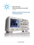
Agilent Technologies
54620-Series Oscilloscopes
Product Overview
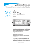
Easily see what's happening in your
mixed analog and digital designs!
• Unique 2 + 16-channel MSO and
2- or 4-channel models
• 2 MB MegaZoom deep memory
per channel
• Patented high-definition display
system
• Flexible triggering including I2C
• 60- and 100-MHz, 200 MSa/s
Multiple configurations to
meet your needs
If you work with both analog and
digital components, Agilent
Technologies 54620-Series
oscilloscopes can help you easily
see more of what's going on in your
designs. The unique 2+16-channel
mixed signal oscilloscope (MSO)
models and the traditional 2- and
4-channel models are optimized with
just the capabilities you need for verifying and debugging designs that
include A/Ds, D/As, DSPs and
embedded 8- or 16-bit microcontrollers. These scopes give you the
tools you need to solve your mixed
analog and digital engineering
challenges more easily.
What makes these scopes so ideal
for mixed analog and digital analysis? The 54620-series scopes combine three critical features:
• 2 MB of MegaZoom deep memory
on each channel so you can capture
long, non-repeating signals,
maintain high sample rate and
quickly zoom in on areas of interest
• a revolutionary ultra-responsive,
high-definition display that's a
clearer "window into your
world" – it lets you see more signal
detail than ever before
• flexible triggering that lets you
easily isolate and analyze the
complex signals and fault
conditions common in mixed analog
and digital designs.
This combination of capabilities is
tailored to give you the measurement
power you need to get your mixed
analog and digital job done faster.
At Agilent Technologies, we focus
on developing products that help
you do your job better. That's why
54620-Series scopes are optimized for
your needs and why they come in a
variety of configurations. Choose the
one that's right for your application
and your budget.
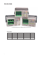
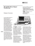
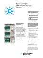
Selection Guide
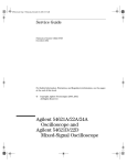
2 + 16-Channel Mixed Signal Oscilloscope (MSO) shown with 2- and 4-channel models
Selection Guide
Model
Agilent 54621A
Agilent 54621D
Agilent 54622A
Agilent 54622D
Agilent 54624A
2
Bandwidth
60 MHz
60 MHz
100 MHz
100 MHz
100 MHz
Sample Rate
200 MSa/s
200 MSa/s
200 MSa/s
200 MSa/s
200 MSa/s
Memory
2 MB/channel
2 MB/channel
2 MB/channel
2 MB/channel
2 MB/channel
Channels
2
2+16
2
2+16
4
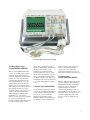
2 + 16-Channel Mixed Signal Oscilloscope (MSO)
The Mixed Signal scopes
(models 54621D and 54622D):
The 60- and 100-MHz mixed signal
oscilloscopes (MSO), with 2 analog
channels and 16 digital channels,
uniquely combine the detailed signal
analysis of a scope with the multichannel timing measurements of a
logic analyzer. They let you see the
complex interactions among your
signals on up to 18 channels at the
same time. No more guesswork and no
more poking around to see a few
channels at a time. These scopes can
easily conquer mixed analog and
digital debugging problems that a
traditional scope can't begin to
address, because they let you simultaneously test and monitor the
high-speed digital control signals and
the slower analog signals in your
design. The combination of analog
channels, digital timing channels and
MegaZoom deep memory with
triggering across all 18 channels
provides totally new ways to debug
mixed analog and digital 8- or 16-bit
microcontroller-based designs. Plus,
the MSOs are built on the same scope
foundation as the other 54620 models,
so they look and feel like a familiar
scope.
4-channel scope (model 54624A):
If your designs include heavy analog
content, the 100-MHz 54624A will give
you the channel count and measurement power you need, including
MegaZoom deep memory, highdefinition display and flexible triggering. Whether you're testing designs
with four inputs, such as anti-lock
brakes, or monitoring multiple
outputs of a power supply, the
4-channel model helps you get your
debug and verification done with ease.
2-channel scopes
(models 54621A and 54622A):
The two-channel models bring all the
benefits of MegaZoom deep memory,
high-definition display, and flexible
triggering to those value-minded
designers with lower channel
requirements. Available in both 60and 100-MHz models, they give you an
affordable way to see long time periods while maintaining high sample
rate so you can see details in your
designs.
3
MegaZoom Deep Memory
With 2 MB of MegaZoom deep memory
behind every channel, 54620-Series
scopes give you deep-memory capture
without the sluggish response and
complex operation you’ve had to
tolerate with other deep-memory
scopes. And unlike the alternatives,
MegaZoom deep memory is not a
special mode; it operates with the
same familiar controls you use for
regular scope measurements. That
means it's always available to help you
do a better job finding details buried
in complex signals, discovering
anomalies in the absence of good trigger events, correlating high-speed
digital control signals with slower
analog signals and capturing infrequent events.
Revolutionary high-definition
display
When you combine MegaZoom deep
memory with a patented highdefinition display system, you get an
accurate and responsive "window into
your world". The MegaZoom deep
memory is mapped into 32 levels of
intensity on a display which has
superior horizontal resolution. And
because the screen update rate is
more than 25 times faster than typical
digital scopes, you get a responsive
display that reflects changes in your
waveform instantaneously – so you
see a more realistic representation of
your signals.
The dilemma of having to trigger twice
to get a long time capture or to see
detailed resolution is solved with
MegaZoom deep memory as you can
have both with a single measurement.
Deep memory means that the sample
rate can be kept high even when
capturing long time periods. You’ll
have a hard time finding another
scope that easily lets you collect 10
milliseconds of data with the ability to
see 5 nanosecond details like you can
with MegaZoom deep memory.
Thanks to multiple processors
optimized for the task of signal
acquisition, storage and display, the
new 54620-Series scopes are the only
deep-memory scopes that respond
instantly to your control inputs, and
have fast, responsive displays and
easy-to-use pan and zoom. Compare
them to other scopes in this price
range – only the 54620-Series gives
you long time capture and detailed
resolution with fast, easy MegaZoom
pan and zoom.
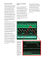
4
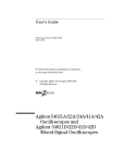
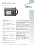
The bright dot on the
high definition display
is a distortion in 1 of
the 1,500 pulses captured in this single
shot measurement.
Simply dial in for a
closer look using
MegaZoom pan and
zoom, and you’ll see
the details that would
have escaped other
scopes, such as the
distortion in this
square wave.
This deep memory
and display system is
not a complex special
mode, either. It is
available on every
measurement pass
at full speed.
This revolutionary design gives you
more insight into your designs than
ever before. With deep memory and a
high-definition display system, there
is less chance to miss a narrow
occasional transient, less chance to
miss a glitch or distorted edge that
impacts circuit operation, and less
chance to miss all those subtle details
that can take weeks to find with a traditional scope.
Flexible triggering
Built-in floppy drive
Other standard features include:
With mixed analog and digital designs,
sometimes it is hard to trace an
anomaly back to its root cause unless
you can trigger on it and correlate it
with another signal. With the 54620Series scopes, triggering is no longer a
hassle. They come with flexible
triggering capabilities (edge, pulse
width, pattern, TV, sequence, I2C and
duration) across all channels so you
can easily isolate and analyze complex
signals and interactions common in
your mixed analog and digital designs.
A built-in 1.44 MB floppy drive makes
it easy for you to store waveform data,
screen images, and scope setups. You
can store your waveform images as
TIF or BMP files and your waveform
data as ASCII files for easy import
into other PC applications. If you
share your lab equipment with others,
you can save your measurement
setups and traces to diskette, making
it simple to reproduce your every-day
setups as well as your advanced configurations.
• Waveform math with FFTs:
Analysis functions include -, *,
Integrate, and Differentiate, as well
as Fast Fourier Transforms.
If you are working with micro-controllers that use I2C serial communications, you'll be glad to discover that
54620-Series scopes help you fine-tune
your debugging. Use I2C trigger mode
to first help verify your inter-IC
communication handshaking. Then
you can use the I2C trigger to ensure
that the correct data is being
transmitted to the desired device.
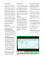
Built-in help
Standard features
Agilent 54620-Series scopes include
the standard features you need to get
your job done easier and faster.
Connectivity made easier
• Parallel and RS-232 interfaces
make connection to printers and
PCs a snap. And the 54620-Series
scopes come with standard parallel
and RS-232 interfaces on the rear
panel. For faster data transfers, an
optional GPIB interface module is
also available.
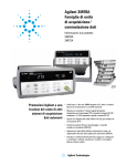
An innovative built-in help system in
nine different languages (English,
French, German, Spanish, Italian,
Japanese, Korean, Traditional and
Simplified Chinese) gives you quick
access to the help you need. If you
have a question about a particular
feature, simply press and hold the
corresponding front-panel key for a
few seconds, and a help screen pops
up to explain its function. You’ll no
longer have to look for the manual
when you need assistance setting up
scope functions or making complex
measurements – help is at your
fingertips.
• 5-ns peak detect means you won't
have to worry about missing narrow
glitches.
• Autoscale lets you quickly display
any active signals, automatically
setting the vertical, horizontal and
trigger controls for the best display.
• Printer connectivity is easy for
Deskjets, Laserjets, or integrated
thermal printer option with the
standard parallel port on the rear
panel.
•High resolution mode offers up to
12 bits of resolution in real-time
(single-shot) modes, reducing noise.
This is accomplished by averaging
sequential data points and mapping
the average to the display when at
slow sweep speeds.
• 3-year warranty: All 54620-Series
scopes include a full 3-year
warranty with optional 5-year
warranty coverage.
• Money-back guarantee: Get a full
refund if you're not satisfied with
your purchase for any reason. See
page 12 for more information.
• IntuiLink, a free software application, simplifies PC connectivity
when you need to transfer images
and waveform data to your PC.
IntuiLink lets you focus more time
on design issues rather than on programming. With the click of a
button on IntuiLink's toolbar, you
can download data or insert a snapshot of an oscilloscope screen
directly into your Microsoft® Excel
spreadsheets or Word documents,
or save the image as a bitmap file.
Once the data is in an Excel spreadsheet, you can leverage Excel's
extensive analysis functions to
create custom graphs and views.
For more information on IntuiLink,
please see the IntuiLink datasheet
with Agilent publication number
5980-3115EN or visit the URL
www.agilent.com/find/intuilink
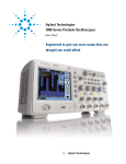
Press and hold any key for built-in Help, such as this description of the frequency
measurement.
5
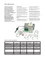
Probes and Accessories
To get the most out of your
scope, you need the right
probes and accessories for
your particular application.
That's why Agilent Technologies
offers a complete family of
innovative probes and 54620-Series
scopes. For more
comprehensive information,
please see the Agilent
54620-Series Oscilloscopes
Probes and Accessories data
sheet. You can get a copy by
calling 1-800-452-4844 or by
visiting our website at
www.agilent.com/find/megazoom.
Passive Probes
Agilent 10070-family passive probes
are high-quality, general-purpose
probes designed for optimal performance with 54620-Series oscilloscopes.
Ruggedized for general-purpose
measurements, these probes are tested to ensure that they operate in the
toughest of conditions. They come
with a variety of accessories to make
your job easier.
Mixed Signal Oscilloscope Logic
Probes
The probes for the 54621D and
54622D MSOs are the same ones used
with Agilent industry-leading high-
performance logic analyzers. This
means we can offer the best
performance, great value and access
to the industry's broadest range of
logic probing accessories.
The 10089A 2 x 8-signal logic probe
with flying leads makes it possible to
connect at several different places on
your DUT. The probe cable provides
two sets of eight channels so you can
work conveniently with only one set if
that's all you require. This probe is
included with your MSO scope.
The 10085A 16-channel logic probe
and termination adapter is designed
to make it easy to connect to industrystandard 20-pin board connectors.
Agilent Passive Probes Selection Guide
10070C
Probe Bandwidth
Probe Risetime (Calculated)
Attenuation Ratio
Input Resistance
(when terminated into 1 MΩ)
Input Capacitance
Maximum Input (dc + peak ac)
Compensation Range
Probe sense
6
20 MHz
< 17.5 ns
1:1
10074C
(shipped with scope)
150 MHz
< 2.33 ns
10:1
10076A
high-voltage probe
250 MHz
< 1.4 ns
100:1
N2771A
high-voltage probe
50 MHz
< 7 ns
1000:1
1 MΩ
Approx 70 pF
500 Vpk CAT I
(mains isolated)
400 Vpk CAT II
(post receptacle mains)
None
Yes
10 MΩ
Approx 15 pF
500 Vpk CAT I
(mains isolated)
400 Vpk CAT II
(post receptacle mains)
9 – 17 pF
Yes
66.7 MΩ
Approx. 3 pF
4000 Vpk
100 MΩ
Approx. 1 pF
15 kV dc, 10 kVrms
30 kV dc + peak ac
6 – 20 pF
Yes
7 – 25 pF
No
Differential Probe
Printer Kit
Use the Agilent N2772A differential
probe with any of the 54620-Series
oscilloscopes to safely measure
floating circuits with the oscilloscope
grounded. With 20 MHz bandwidth
and switchable attenuation of 20:1
and 200:1, this probe provides the
versatility for a broad range of
applications including high-voltage
circuits.
high bandwidth current probe featuring wide bandwidth (DC-50MHz),
low noise (<2.5 mArms) and low circuit
insertion loss. The probes use
hall-effect technology to measure dc
current and a current transformer to
sense ac current. The N2774A requires
an Agilent N2775A power supply.
This probe requires a 9 V battery or an
Agilent N2773A power supply.
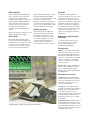
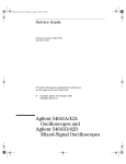
Agilent's Wedge probe adapter for
probing 0.5 mm and 0.65 mm ICs is
mechanically non-invasive, so you
get reliable contact with no chance
of shorting. Available in 16-, 8- and
3-signal versions, this innovative
accessory makes connecting to
fine-pitch ICs easier than ever before.
Current Probe
The Agilent 1146A AC/DC current
probe provides accurate display and
measurement of current from 100 mA
to 100 Arms, dc to 100 KHz, without
needing to make an electrical connection to the circuit. The N2774A is a
Wedge probe adapter
The Agilent N2727A printer kit
provides everything you need for easy
documentation directly from your
54620-Series scope. It lets you easily
print the screen display and key setup
parameters and is powered directly
from the oscilloscope. In addition to
the thermal printer, the kit includes a
printer pouch, a parallel cable, power
cable and enough paper for you to
print 200 screen images with setup
information.
BNC adapters and feed-through
terminations
See the 54620-Series Probes and
Accessories data sheet for a wide
variety of BNC adapters and
feed-through terminations.
PC connectivity
GPIB: If you need fast data transfers,
equip your 54620-Series scope with
the optional N2757A GPIB interface
module that easily snaps on the rear
of the scope. Agilent also offers GPIB
cards for your PC as well as GPIB
cables to complete the connection to
your test system.
RS-232 cable: If you need an RS-232
cable for your 60-MHz 54620-Series
scope, order the Agilent 34398A
RS-232 cable. It comes standard with
100-MHz models.
Miscellaneous accessories
Testmobile scope cart: The Agilent
1183A testmobile makes sharing your
scope easy. A Kinsington lock can be
attached to the rear of the scope to
secure your equipment.
Carrying case: The Agilent 1185A
carrying case makes transporting and
shipping your 54620-Series oscilloscope safe and simple. A scope,
optional module and other accessories
fit neatly inside the padded shell of
hard plastic and the case is lockable
for shipment.
16-pin Wedge probe adapter for probing 0.5 mm or 0.65 mm ICs
Rack mount kit: The Agilent 1186A or
option 1CM rack mount kit positions
your 54620-Series scope in the center
of the rack. Each kit includes a custom
shelf with rails, 6 BNC pass-throughs
and all necessary screws.
7
Performance Characteristics
* Denotes Warranted Specifications, all others are typical. Specifications are valid after a 30-minute warm-up period and ± 10°C from firmware calibration temperature.
Acquisition: Analog Channels
Sample Rate
200 MSa/s maximum per scope
channel
Memory Depth
2 MB/channel
4 MB max with single scope channel
on (Single mode)
Vertical Resolution
8 bits
Peak Detection
5 ns
Averaging
selectable from 2, 4, 8, 16, 32, 64 …
to 16k
High Resolution Mode
12 bits of resolution when > 200
us/div, (average mode with ave = 1)
Filter:
Sinx/x interpolation (single shot BW
= sample rate/4) with vectors on.
Acquisition: Digital Channels
(on 54621D and 54622D only)
Sample Rate
400 MSa/s maximum
Memory Depth Per Channel
8 channels same pod
8 MB/channel maximum
2 pods in use
4 MB/channel maximum
Vertical Resolution
1 bit
Glitch Detection (min pulse width)
5 ns
Vertical System: Analog Channels
Scope Channels
54621A/D, 54622A/D
Ch 1 and 2 simultaneous acquisition
54624A Ch 1, 2, 3 and 4 simultaneous acquisition
54621A/D
Bandwidth (~3 dB)*
dc to 60 MHz
ac coupled
3.5 Hz to 60 MHz
Calculated risetime
~5.8 ns (= 0.35/bandwidth)
54622A/D, 54624A
Bandwidth (~3 dB)*
dc to 100 MHz
ac coupled
3.5 Hz to 100 MHz
Calculated risetime
~3.5 ns (= 0.35/bandwidth)
Single Shot Bandwidth
50 MHz
1
1 mV/div is a magnification of 2 mV/div setting. For vertical accuracy calculations, use full scale of 16 mV for 1
mV/div sensitivity setting.
8
Range1
1 mV/div to 5 V/div
Maximum Input
CAT I 300 Vrms, 400 Vpk
CAT II 100 Vrms, 400 Vpk
with 10074C 10:1 probe:
CAT I 500 Vpk, CAT II 400 Vpk
Offset Range
± 5 V on ranges < 10 mV/div
±25 V on ranges 10 mV/div to
199 mV/div
±100 V on ranges ≥ 200 mV/div
Dynamic Range
Lesser of ± 8 div or ± 32 V
Input Resistance
1 MΩ ± 1%
Input Capacitance
~ 14 pF
Coupling
ac, dc, ground
BW Limit
~ 20 MHz selectable
Channel-to-Channel Isolation
dc to 20 MHz > 40 dB (with channels
at same V/div);
20 MHz to max bandwidth > 30 dB
Probes
10:1 10074C shipped standard for
each analog channel
Probe ID (Agilent/HP & Tek Compatible)
Auto probe sense
ESD Tolerance
± 2 kV
Noise Peak-to-Peak
2% full scale or 1 mV, whichever is
greater
Common Mode Rejection Ratio
20 dB @ 50 MHz
DC Vertical Gain Accuracy* 1
± 2.0% full scale
DC Vertical Offset Accuracy
< 200 mV/div
± 0.1 div ± 1.0 mV ± 0.5% offset
value
≥ 200 mV/div
± 0.1 div ± 1.0 mV ± 1.5% offset
value
Single Cursor Accuracy 1
±{DC Vertical Gain Accuracy + DC
Vertical Offset Accuracy + 0.2% full
scale (~1/2 LSB) }
Example: for 50 mV signal, scope set
to 10 mV/div (80 mV full scale),
5 mV offset, accuracy =
±{2.0%(80 mV) + 0.1 (10 mV) +
1.0 mV + 0.5% (5 mV) + .2%(80 mV)}
= ± 3.78 mV
Dual Cursor Accuracy* 1
±{DC Vertical Gain Accuracy + 0.4%
full scale (~1 LSB)}
Example: for 50 mV signal, scope set
to 10 mV/div (80 mV full scale),
5 mV offset, accuracy =
±{2.0%(80 mV) + .4%(80 mV)} =
± 1.92 mV
Vertical System: Digital Channels
(54621D and 54622D only)
Number of Channels
16 Digital – labeled D15 – D0
Threshold Selections
Pod 1: D7 – D0, Pod 2: D15 – D8
Maximum Input Voltage
± 40 V peak CAT I
Threshold Range
± 8.0 V in 10 mV increments
Threshold Accuracy*
± (100 mV + 3% of threshold setting)
Input Dynamic Range
±10 V about threshold
Minimum Input Voltage Swing
500 mV peak-to-peak
Input Capacitance
~ 8 pF
Input Resistance
100 kΩ, ±2% at probe tip
Channel-to-Channel Skew
2 ns typical, 3 ns maximum
Horizontal:
Range
5 ns/div to 50 s/div
Resolution
40 ps
Vernier
1-2-5 increments when off, 25 minor
increments between major settings
when on
Reference Positions
Left, Center, Right
Delay Range
Pre-trigger (negative delay)
Greater of 1 screen width or 10 ms
Post-trigger (positive delay)
500 seconds
Analog Delta-t Accuracy
Same Channel*
± 0.01% reading ± 0.1% screen
width ± 40 ps
Example: for signal with pulse width
of 10 µs, scope set to 5 µs/div (50 µs
screen width), delta-t accuracy =
±{.01%(10 µs) +
0.1%(50 µs) + 40 ps} = 51.04 ns
Channel-to-Channel
± 0.01% reading ± 0.1% screen
width ± 80 ps
Performance Characteristics
* Denotes Warranted Specifications, all others are typical. Specifications are valid after a 30-minute warm-up period and ± 10°C from firmware calibration temperature.
Digital Delta-t Accuracy (non-Vernier settings)
Same Channel
± 0.01% reading ± 0.1% screen
width ± (1 digital sample period,
2.5 or 5 ns based on sample rate of
200/400 MSa/s)
Example: for signal with pulse
width of 10 µs, scope set to
5 µs/div (50 µs screen width), and
single pod active (400 MSa/s),
delta-t accuracy= ±{.01%(10 µs) +
0.1% (50 µs) + 2.5 ns} = 53.5 ns
Channel-to-Channel
± 0.01% reading ± 0.2% screen
width ± (1 logic sample period,
2.5 or 5 ns) ± chan-to-chan skew
(2 ns typical, 3 ns maximum)
Delay Jitter
10 ppm
RMS Jitter
0.025% screen width + 100 ps
Modes
Main, Delayed, Roll, XY
XY
Z Blanking
1.4 V blanks trace
(use external trigger)
Bandwidth
Max bandwidth
Phase error @ 1 MHz
1.8 degrees
Trigger System:
Sources:
54621A/622A
Ch 1, 2, line, ext
54621D/622D
Ch 1, 2, line, ext, D15 – D0
54624A
Ch 1, 2, 3, 4, line, ext
Modes
Auto, Auto level, Triggered (normal),
Single
Holdoff Time
~60 ns to 10 seconds
Selections
Edge, Pattern, Pulse Width, TV,
Sequence, I2C, Duration
Edge
Trigger on a rising or falling edge of
any source.
Pattern
Trigger on a pattern of high, low, and
don’t care levels and a rising or
falling edge established across any
of the sources. The analog channel’s high or low level is defined by
that channel’s trigger level.
Pulse Width
Trigger when a positive- or negativegoing pulse is less than, greater
than, or within a specified range on
any of the source channels.
Minimum pulse width setting
5 ns
Maximum pulse width setting
10 s
TV
Trigger on any scope channel for
NTSC, PAL, PAL-M, or SECAM
broadcast standards on either positive or negative composite video signals. Modes supported include Field
1, Field 2, or both, all lines, or any
line within a field. Also supports
triggering on non-interlaced fields.
TV trigger sensitivity: 0.5 division of
synch signal.
Sequence
Arm on event A, trigger on event B,
with option to reset on event C or
time delay.
I2C
Trigger on I2C (Inter-IC bus) serial
protocol at a start/stop condition or
user defined frame with address
and/or data values.
Duration
Trigger on a multi-channel pattern
whose time duration is less than a
value, greater than a value, greater
than a time value with a timeout
value, or inside or outside of a set of
time values.
Minimum duration setting:
5 ns
Maximum duration setting:
10 s
Autoscale
Finds and displays all active analog
and digital channels (for
54621D/54622D), sets edge trigger
mode on highest numbered channel,
sets vertical sensitivity on analog
channels and thresholds on digital
channels, time base to display ~1.8
periods. Requires minimum voltage
> 10 mVpp, 0.5% duty cycle and minimum frequency > 50 Hz.
Analog Channel Triggering:
Range (Internal)
± 6 div
Sensitivity*
Greater of 0.35 div or 2.5 mV
Coupling
ac (~3.5 Hz), dc, noise reject, HF
reject and LF reject (~ 50 kHz)
Digital (D15 – D0) Channel Triggering
(54621D and 54622D):
Threshold Range (user defined)
±8.0 V in 10 mV increments
Threshold Accuracy*
± (100 mV + 3% of threshold setting)
Predefined Thresholds
TTL = 1.4 V, CMOS = 2.5 V,
ECL = -1.3 V
External (EXT) Triggering:
Input Resistance
1 MΩ, ±3%
Input Impedance
~ 14 pF
Maximum Input
CAT I 300 Vrms, 400 Vpk
CAT II 100 Vrms, 400 Vpk
with 10074C 10:1 probe:
CAT I 500 Vpk, CAT II 400 Vpk
Range
± 10 V
Sensitivity
dc to 25 MHz, < 75 mV
25 MHz to max bandwidth,
< 150 mV
Coupling
ac (~ 3.5 Hz), dc, noise reject,
HF reject and LF reject (~ 50 kHz)
Display System
Display
7-inch raster monochrome CRT
Throughput of Analog Channels
25 million vectors/sec per
channel with 32 levels of intensity
Resolution
255 vertical by 1000 horizontal
points (waveform area)
32 levels of gray scale
High-performance custom graphics display
processor
400 MB/sec graphics BW / channel
2 MB SGRAM (Agilent 54621A/D
and 54622A/D)
4 MB SGRAM (Agilent 54624A)
9
Performance Characteristics
* Denotes Warranted Specifications, all others are typical. Specifications are valid after a 30-minute warm-up period and ± 10°C from firmware calibration temperature.
Controls
Waveform intensity on front panel
Vectors on/off; infinite persistence
on/off
8 x 10 grid with continuous intensity
control
Built-in Help System
Key-specific help in 9 languages displayed by pressing and holding key
or softkey of interest
Real Time Clock
Time and date (user setable)
Measurement Features
Automatic Measurements
Measurements are continuously
updated
Cursors track current measurement
Voltage (analog channels only)
Peak-to-Peak, Maximum, Minimum,
Average, Amplitude, Top, Base,
Overshoot, Undershoot, RMS (front
panel: dc; GPIB: ac and dc)
Time
Frequency, Period, + Width,
- Width, Duty Cycle, X at Max (Time
at max volts), delay, phase on any
channels. Rise time and Fall time on
analog channels only
Threshold Definition
10%, 50%, 90% for time measurements
Cursors
Manually or automatically placed
readout of Horizontal (X, ∆X, 1/∆X)
and Vertical (Y, ∆Y). Additionally digital or analog channels can be displayed as binary or hex values
Waveform Math
1-2, 1*2, FFT, dV/dt, ∫Vdt.
Source of FFT, dV/dt, ∫Vdt: scope
channels 1 or 2, 1-2, 1+2, 1*2
FFT
Points
Fixed at 2048 points
Source of FFT
Scope channels 1 or 2, 1+2, 1-2, 1*2
Window
Rectangular, Flattop, Hanning
Noise Floor
-70 to -100 dB depending on averaging
Amplitude Display
In dBV
Frequency Resolution
0.097656/(time per div.)
Maximum Frequency
102.4/(time per div.)
10
Storage
Environmental Characteristics:
Save/Recall (non-volatile)
3 setups and traces can be saved
and recalled internally
Floppy Disk
3.5" 1.44 MB double density
Image formats
TIF, BMP
Data formats
X and Y (time/voltage) values in CSV
format
Trace/setup formats
Recalled
Ambient Temperature
Operating –10°C to +55°C
Non-operating –51°C to +71°C
Humidity
Operating 95% RH at 40°C for 24 hr
Non-operating 90% RH at 65°C for
24 hr
Altitude
Operating to 4,570 m (15,000 ft)
Non-operating to 15,244 m (50,000 ft)
Vibration
HP/Agilent class B1 and MIL-PRF28800F Class 3 random
Shock
HP/Agilent class B1 and MIL-PRF28800F (operating 30 g, 1/2 sine,
11-ms duration, 3 shocks/axis along
major axis. Total of 18 shocks)
I/O
RS-232 (serial) standard port
1 port: XON or DTR; 8 data bits;
1 stop bits; parity; 9600, 19200,
38400, 57600 baud rates
Parallel standard port
Printer support
Printer Compatibility
DeskJet, LaserJet with HP PCL 3 or
greater compatibility
black and white @ 150x150 dpi
gray scale @ 600x600 dpi
Epson
black and white @180x180 dpi
Seiko thermal DPU-414
black and white
Optional GPIB Module
Fully programmable with IEEE488.2
compliance
Typical GPIB throughput of 20 measurements or
20 2000-point records per second
General Characteristics
Physical:
Size
32.26 cm wide x 17.27 cm high x
31.75 cm deep (without handle)
Weight 6.35 kgs (14 lbs)
Calibrator Output
Frequency ~1.2 kHz; Amplitude ~5 V
Trigger Out
0 to 5 V with 50 Ω source impedence; delay ~55 ns
Printer Power
7.2 to 9.2 V, 1 A
Kensington lock
connection on rear panel for security
Power Requirements:
Line Voltage Range
100 – 240 VAC ±10%, CAT II, automatic selection
Line Frequency
47 to 440 Hz
Power Usage
100 W max
Regulatory Information:
Safety
IEC 610101:1990+A1:1992+A2:1995/ EN
61010-1:1994+A2:1995
UL 3111
CSA-C22.2 No. 1010.1:1992
Supplementary Information: The product herewith complies with the requirements of the Low
Voltage Directive 73/23/EEC and the EMC
Directive 89/336/EEC, and carries the CE-marking accordingly. The product was tested in a typical configuration with HP/Agilent test systems.
Ordering Information
Passive Probes
54621A 2-channel 60 MHz Oscilloscope
54621D 2+16 channel 60 MHz Mixed Signal Oscilloscope
54622A 2-channel 100 MHz Oscilloscope
54622D 2+16 channel 100 MHz Mixed Signal Oscilloscope
54624A 4-channel 100 MHz Oscilloscope
Accessories Included:
User’s Guide (localized), Service Manual,
Programmer’s Manual
Power cord
10074C 10:1 divider probes with readout
16:2 x 8 input logic input probe assembly
Accessories pouch and front panel cover
IntuiLink software
RS-232 cable
10070C 1:1 passive probe
with ID
10074C 10:1 150 MHz
passive probe with ID
54621A
54621D
54622A
54622D
54624A
•
•
2
•
•
2
•
•
•
2
•
•
4
•
•
•
2
•
•
•
•
•
**
**
•
** IntuiLink Software available free on web at www.agilent.com/find/gp
Manual Options
(if no option is specified, English ABA will be shipped)
ABA English
ABD German
ABE Spanish
ABF French
ABZ Italian
ABJ Japanese
ABO Traditional Chinese
AB1 Korean
AB2 Simplified Chinese
Available Options
Option 003 Shielding Option for use in severe environments
or with sensitive devices under test – shields both ways (in and out):
RS-03 Magnetic interface shielding added to CRT, and RE-02 display
shield added to CRT to reduce radiated interference
Option 0B0 Delete manuals
Option 1CM Rackmount kit (same as 1186A)
Warranty and Calibration Options:
All models include a standard 3-year warranty.
Contact local sales office for prices of extended options:
A6J ANSI/NSCL Z540 calibration with test data (replaces 1BP)
W32 3-year, customer-return calibration service
W34 3-year, customer-return standard comp cal service
W50 Additional 2-year warranty (5 year total)
W52 5-year, customer-return calibration service
W54 5-year, customer-return standard comp cal service
Accessories
1183A Testmobile scope cart
1185A Carrying case
1186A Rackmount kit (same as option ICM)
N2726A Accessory pouch & front panel cover
(standard with 100-MHz models, optional with 60-MHz models)
N2727A Seiko thermal printer and pouch
parallel cable, power cable, 2 rolls paper, front panel cover
N2728A 10 rolls of printer paper
N2757A GPIB interface module for 54621A/D, 54622A/D or 54624A scopes
Fine Pitch Probing
10072A Fine-pitch probe kit
10075A 0.5 mm IC clip kit
E2613B
0.5mm Wedge probe adapter,
3-signal, qty 2
E2614A .
0.5 mm Wedge probe adapter,
8-signal, qty 1
E2643A
0.5 mm, Wedge probe adapter
16-signal, qty 1
E2615B
0.65mm, Wedge probe adapter,
3-signal, qty 2
E2616A
0.65 mm, Wedge probe adapter,
8-signal, qty 1
E2644A
0.65 mm,Wedge probe adapter,
16-signal, qty 1
Current Probe
1146A 100 kHz
Current probe, ac/dc
N2774A 50 MHz
current probe, ac/dc
N2775A .
power supply for N2774A
High Voltage Probes
10076A 100:1, 4 kV
250 MHz probe with ID
N2771A 1000:1, 15 kV,
50 MHz high voltage probe
Logic Probes
10085A 16:16 logic cable
and terminator (for use
with 54621D/622D)
10089A 16:2 x 8 logic input
probe assembly (shipped
standard with 54621A/622D)
Differential Probe
N2772A 20 MHz differential
probe
N2773A Differential probe
power supply
Cables
10833A GPIB cable, 1m long
34398A RS-232 cable
(standard with 100 MHz scopes)
11
Call the measurement experts at
Agilent Technologies
Agilent Technologies'
Test and Measurement Support
Whether your work is mostly digital, mostly analog, or somewhere in the middle, our measurement specialists can help you select the best
debugging solution. Call today to talk to a knowledgeable engineer about your particular application.
Services, and Assistance
Agilent Technologies aims to maximize the value
you receive, while minimizing your risk and problems. We strive to ensure that you get the test
and measurement capabilities you paid for and
obtain the support you need. Our extensive support resources and services can help you choose
the right Agilent products for your applications
and apply them successfully. Every instrument
and system we sell has a global warranty.
Support is available for at least five years beyond
the production life of the product. Two concepts
underlay Agilent's overall support
policy: "Our Promise" and "Your Advantage."
See for yourself with a no-obligation, 2-week
demo
If you'd like to see for yourself how an Agilent
54620-Series scope can help you solve your mixed
analog and digital design problems, just give us a
call. We'll arrange for you to use a 54620-Series
scope in your lab for two weeks with no obligation
to buy. Call 1-800-452-4844 and ask for Direct
Demo or visit our website:
www.agilent.com/find/megazoom
Money-back guarantee
Get a full refund if you’re not satisfied with your
purchase for any reason within 60 days in the USA
or 90 days outside of the USA.
Our Promise
Our Promise means your Agilent test and measurement equipment will meet its advertised performance and functionality. When you are choosing new equipment, we will help you with product information, including realistic performance
specifications and practical recommendations
from experienced test engineers. When you use
Agilent equipment, we can verify that it works
properly, help with product operation, and provide basic measurement assistance for the use of
specified capabilities, at no extra cost upon
request. Many self-help tools are available.
Your Advantage
Your Advantage means that Agilent offers a wide
range of additional expert test and measurement
services, which you can purchase according to
your unique technical and business needs. Solve
problems efficiently and gain a competitive edge
by contracting with us for calibration, extra-cost
upgrades, out-of-warranty repairs, and on-site
education and training, as well as design, system
integration, project management, and other professional engineering services. Experienced
Agilent engineers and technicians worldwide can
help you maximize your productivity, optimize the
return on investment of your Agilent instruments
and systems, and obtain dependable measurement accuracy for the life of those products.
By internet, phone, or fax, get assistance with all
your test & measurement needs
Online assistance:
www.agilent.com/find/assist
Phone or Fax
United States:
(tel) 1 800 452 4844
Canada:
(tel) 1 877 894 4414
(fax) (905) 282-6495
Europe:
(tel) (31 20) 547 2323
(fax) (31 20) 547 2390
Japan:
(tel) (81) 426 56 7832
(fax) (81) 426 56 7840
Latin America:
(tel) (305) 269 7500
(fax) (305) 269 7599
Australia:
(tel) 1 800 629 485
(fax) (61 3) 9210 5947
New Zealand:
(tel) 0 800 738 378
(fax) 64 4 495 8950
Asia Pacific:
(tel) (852) 3197 7777
(fax) (852) 2506 9284
Product specifications and descriptions in this
document subject to change without notice.
Copyright © 2000 Agilent Technologies
Printed in U.S.A.
January 1, 2001
5968-8152EN