1
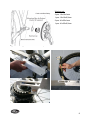
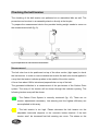
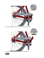
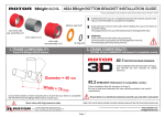
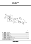
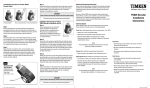
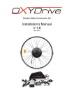
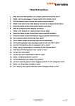
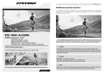
Universal transmissions GmbH
Külftalstr. 18
31093 Lübbrechtsen
Germany
phone: (49)-5185-60266-50
[email protected]
www.carbondrivesystems.com
GATES belt ruler and tension tester
User manual
Thank you for choosing the Carbon Drive equipment to install the drive system
correctly. On the following pages a testing method will introduced to check easily the
correct belt line and the belt tension.
Please read this manual carefully before you start with the first measurements.
If you got any additional questions to the measurement procedure feel free to contact
us. [email protected] .
fig. 1: Multi purpose tool to check the belt line and the belt tension
1
Content
Basics ......................................................................................................................... 3
Part list........................................................................................................................ 4
Checking the beltline .................................................................................................. 5
Adjustment of the belt line .......................................................................................... 8
Checking the belt tension ......................................................................................... 10
Measurement............................................................................................................ 10
2
Basics
Beltline:
A correct aligned belt line is absolutely required to receive a secure and carefree
system. The correct beltline is also important to receive the high efficiency of the
system. The beltline is specified by the used hub type. The Position of the front
sprocket needs to be aligned depending on the hub type. The fine adjustments are
also necessary in order to compensate the frame or component tolerances.
The front sprocket and the rear pulley should aligned in a way that they are located
on one plane. An incorrect aligned beltline is shown on fig. 2. The displacement (a) of
the sprockets will lead the belt to run of the sprockets. This procedure could damage
the belt and might cause a dangerous crash. Displacements of the sprockets can
also increase the friction of the system and therefore decrease the efficiency.
fig 2: Incorrect aligned beltline. Displacement shown through a
Belt tension:
Proper belt tension is absolutely required to receive a secure and durable drive
system. A belt tension against the specification can lead to an increased wearing.
Lack of belt tension can lead to so-called ”ratcheting”, which means that the belt will
jump over the teeth of the rear pulley. Ratcheting could damage the carbon tensile
cords.
3
Part list
Nr.
Quantity.
Description
01
1 pcs.
base
02
1 pcs.
testing weigth 1Kg
03
1 pcs.
guide plate
04
1 pcs.
adjustment bar
05
2 pcs.
washer
06
1 pcs.
testing needle
07
1 pcs.
tension indicator
08
1 pcs.
measurement shaft
09
2 pcs.
cylinder head bolt M8 x 16mm
10
1 pcs.
cylinder head bolt M5 x 12mm
10
4 pcs.
counter sunk bolt M6 x 14mm
11
2 pcs.
dowel 6 x 14mm
12
1 pcs.
set screw M5
Illustration
The measurement device is already pre-assembled. To make the individual
adjustments please use the following tools. Tools are not included in delivery
1x 6mm Allen key
1x 4mm Allen key
4
Checking the beltline
The measurement device can be used on a fully equipped bicycle. It is useful to fix
the bike in an assembly stand in order to get an ergonomic position to check the
beltline. Please consider that the chain stays are aligned parallel to the ground (fig.
3). Please pay attention to the secure stand of the assembly stand!
fig. 3: Bicycle fixed in an assembly stand
The testing weight is not necessary to check the beltline. Please remove the weight
before measuring. As a first step the fine adjustment of the measurement device
needs to be done. Via the adjustment bar the device can be adjusted in order to
match the device to different chain stay length. Please loose the two M8 cylinder
head bolts which are fixing the adjustment bar (fig. 4, Pos. 1). Afterwards the length
can be adjusted in a way that the testing needle reaches the inside flange of the rear
pulley.
The testing needle is an indicator if the belt line is aligned correctly. The needle has
to be proper adjusted to the different beltlines as well. Please loose the M5 cylinder
head bolt to adjust the testing needle (fig.4, Pos. 2.).
5
Pos. 2
Pos. 1
fig. 4: Fastening bolts to adjust the belt ruler
The beltline is specified by the used hub. Three possible beltlines are listed in the
chart below (Chart 1).
Chart 1: Measurements at the testing needle
Measurement at the
Hub type
testing needle
D
Rohloff Speedhub
Shimano
Nexus/
Alfine
9Spline freewheel
body
10,0mm
12,0mm
13,0mm
Please adjust the testing needle to the used hub type. The value D should be
measured at the surfaces which are shown in fig. 5.
fig. 5: Partial view of the belt ruler. Measuring face to adjust the belt line
6
The belt ruler is now adjusted properly. Please follow the next step to check the belt
line.
To check the belt line the belt ruler needs to be positioned at the mounted front
sprocket with its parallel face (fig. 6).
If the belt line is already adjusted the face of the testing needle should touch the
inside of the flange of the rear sprocket.
fig. 6: test setup to check the belt line
In the case that the belt line is not aligned properly please use the following
procedure to receive the correct adjustment.
7
Adjustment of the belt line
The beltline can be adjusted by using the washer set. The washer set is included in
the front sprocket delivery. It consists of washers with two different thicknesses to be
able to fine adjust the belt line.
The needed washers are mounted between the surface oft he crank arm and the
front sprocket (fig. 7). Some bottom bracket units (e.g. Shimano Hollowtech or
Truvativ GXP) allow the fine adjustment via washers between the bottom bracket
shell and the BB housing (fig. 8). Please pay attention to the instructions for
installation of the bottom bracket which is supplied by the BB manufacturer.
fig. 7: Assembly of the front sprocket
If your bike is equipped with an eccentric bottom bracket you can set the belt
line by adjusting the bottom bracket unit axial in the bottom bracket housing. Please
pay attention to the instructions for installation of the eccentric bottom bracket which
is supplied by the bike manufacturer.
8
Washer set:
2 pcs. 10x16x1mm
1 pcs. 10x16x0,5mm
2 pcs. 41x35x1mm
1 pcs. 41x35x0,5mm
fig 8: belt line alignment via bottom bracket spacer
9
Checking the belt tension
The checking of the belt tension can perfomed at an assembled bike as well. The
procedure can be done in an assembly stand or directly at the bicycle.
To prepare the measurement device the provided testing weight needs to screw on
the measurement shaft (fig. 9).
fig 9: Preparation for the tension measurement
Measurement
The belt ruler has to be positioned on top of the drive section (tight span) to check
the belt tension. In order to receive reliable test results the belt ruler should applied in
a way that the tension indicator pushes in the middle of the drive section.
A force from about 10N is introduced perpendicular on top of the belt.
The generated deflection is a measurement of the pre-tension of the Carbon Drive
system. The array of the tension will be shown through the indicator opening. The
following tension arrays will be shown:
- The Carbon Drive System is correctly tensioned (fig. 10). There are no
tension adjustments necessary. Low wearing and the highest efficiency are
accomplished in this array.
- The belt tension is too high. Please decrease the belt tension via the
adjustable horizontal dropouts or the eccentric bottom bracket. If the belt
tension won´t be increased fast belt wearing can occur. The stress on the
bearings of the rear hub and the bottom bracket will also raise to a level where
high wearing is possible.
- The belt tension is to low (fig. 11). Please decrease the tension of the belt via
the horizontal dropouts or the eccentric bottom bracket. Lack of belt tension
can lead to so-called ”ratcheting”, which means that the belt will jump over the
teeth of the rear pulley. Ratcheting can damage the carbon tensile cords.
Important!
Initial setting:
The carbon fibers on the inside of the belt are in an unstressed state before the first
assembly. If the belt is mounted for the first time and tensioned for the first time, the
carbon fibers move to their working position (tensioned). This process causes a
minimal change in length of the belt. This is called initial settling. To compensate this
settling behavior the belt will be tensioned about 15% above the optimum belt
tension. The belt tension during first assembly can also be easily verified with the belt
ruler. Prior to delivery of the bike to the customer the tension indicator should show
50% yellow and 50% green in the indicator opening
Tip: The belt ruler can be positioned on top of the belt while tensioning the belt
via the horizontal dropouts or the eccentric BB Unit. This is an easy way to notice
when the belt is tensioned correctly.
fig10: Correct belt tension. Green array is shown in the indicator
indi
opening
fig 11: Belt tension low. Red array is shown in the indicator opening