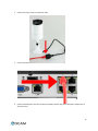
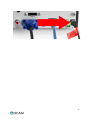
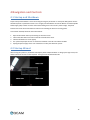
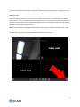
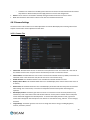
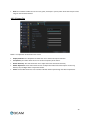
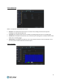
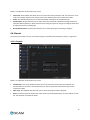
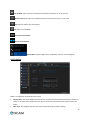
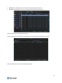
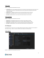
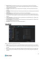
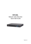
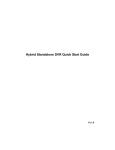
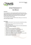
1
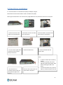
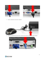
Qcam NVR User Manual
1
Contents
Welcome ........................................................................................................................................................................4
Important Safeguards and Warnings .............................................................................................................................5
1 Features and Specifications ........................................................................................................................................6
1.1 Overview ..............................................................................................................................................................6
2 Device and Peripheral Details .....................................................................................................................................7
2.1 Front Panel...........................................................................................................................................................7
2.2 Rear Panel ............................................................................................................................................................8
2.3 Mouse ..................................................................................................................................................................9
2.4 Soft Keyboard ......................................................................................................................................................9
3 Device Installation ......................................................................................................................................................9
3.1 Check Hardware.................................................................................................................................................10
3.2 Hard Drive Installation .......................................................................................................................................11
3.3 Connection Port Information .............................................................................................................................12
3.3.1 Power Supply Connection ...........................................................................................................................12
3.3.2 Audio Output Connection ...........................................................................................................................12
3.4 Device Assembly Guide ......................................................................................................................................12
4 Navigation and Controls ...........................................................................................................................................16
4.1 Startup and Shutdown .......................................................................................................................................16
4.2 Startup Wizard ...................................................................................................................................................16
4.3 Main Menu Introduction ...................................................................................................................................22
4.4 Local & Remote Access Setup ............................................................................................................................22
4.4.1 Local Access Setup ......................................................................................................................................22
4.4.2 Remote Access Setup..................................................................................................................................24
4.5 Live View Interface and Controls .......................................................................................................................25
4.5.1 Camera Status Icons ...................................................................................................................................25
2
4.5.2 Preview Toolbar ..........................................................................................................................................25
4.5.3 Menu Toolbar .............................................................................................................................................26
4.5.4 Digital Zoom ................................................................................................................................................26
4.5.5 PTZ Control .................................................................................................................................................27
4.5.5.1 PTZ Presets, Patrols, and Patterns ...........................................................................................................27
4.5.5.2 PTZ Context Menu ...................................................................................................................................27
4.6 Main Menu Definitions ......................................................................................................................................28
4.6.1 IP Channel ...................................................................................................................................................28
4.6.2 Camera Settings ..........................................................................................................................................29
4.6.3 Recording ....................................................................................................................................................31
4.6.4 Search .........................................................................................................................................................33
4.6.5 Network ......................................................................................................................................................37
4.6.6 Alarm ..........................................................................................................................................................39
4.6.7 Device .........................................................................................................................................................43
4.6.8 System ........................................................................................................................................................46
4.7 Qcam Link App Setup .........................................................................................................................................50
4.8 Qcam Link App Interface ...................................................................................................................................54
4.9 Web Access Interface ........................................................................................................................................55
4.10 Qcamlink.com Web Access ..............................................................................................................................57
Appendix A: Toxic or Hazardous Materials or Elements..............................................................................................58
3
Welcome
Thank you for purchasing the Qcam Network Video Recorder (NVR)!
This user manual is designed to be a reference tool for the installation and operation of your NVR.
Here you can find information about the NVR’s features and functions, as well as information to aid in
troubleshooting.
For access to the quick start guide and other support information, go to http://qcam.com/support
To contact Qcam support, please do one of the following:
•
•
•
Visit http://qcam.com/contacts and use the email form
Visit http://qcam.com/support
Email Qcam Customer Support [email protected]
4
Important Safeguards and Warnings
Important Safeguards and Warnings
1.Electrical Safety
All installation and operation should conform to your local electrical safety codes.
The product must be grounded to reduce the risk of electric shock.
We assume no liability or responsibility for any fires or electrical shock caused by improper handling or installation.
2.Transportation Security
Heavy stress, violent vibrations, and excess moisture should not occur during transportation, storage, and
installation of the device.
3.Installation
Handle the device with care. Keep the device right side up.
Do not apply power to the NVR before completing installation.
Do not place objects on top of the NVR.
4.Repair Professionals
All the examination and repair work should be done by qualified service engineers.
We are not liable for any problems caused by unauthorized modifications or user-attempted repair.
5.Environment
The NVR should be installed and kept in a cool, dry place away from direct sunlight, flammable materials, explosive
substances, etc.
This product should be transported, stored, and used only in the specified environments as stated above.
6. Accessories
Be sure to use only the accessories recommended by manufacturer.
Before installation, please open the package and check to ensure that all of the components are present.
Contact the retailer that you purchased from, or Qcam directly if anything is broken or missing in the package.
5
1 Features and Specifications
1.1 Overview
The Qcam NVR is a high performance network video recorder. It supports local preview, multiple-window display,
local storage of recordings, remote control usage, mouse shortcut menu operations, and remote access.
The NVR supports multiple storage methods and can save to a variety of locations. Working with a wide variety of
cameras, this NVR can store video from IPC cameras, NVS cameras, as well as many other types. By using standard
network Ethernet cables, the NVR can easily be setup through the use of existing wiring.
Due to the NVR’s versatile and robust design, video surveillance can be easily brought to a wide variety of
industries.
1.2 Features
The Qcam NVR has the following features:
•
Compression
The NVR supports 1MP, 1.3MP, 2MP, and 3MP IP cameras. Video encoding parameters, such as frame rate
and bit rate, can be set separately for each channel. The NVR also supports composite and video only streams,
however, audio and video streams are strictly simultaneous.
•
Monitoring
The NVR supports VGA and HDMI video output, and the display resolution supports up to 1080p. The interface
allows the user to show 1, 4, 8, 9, 16, or 32 camera live view windows at once. Digital zoom is available on all
cameras within the live view, as well as privacy masks. Additionally the camera can also use PTZ on any PTZenabled cameras.
•
HDD Management
The NVR supports anywhere from 1 to 8 SATA hard drives (up to 4TB), and up to 2 eSATA hard drives (up to
4TB). Another key feature of the NVR is its use of S.M.A.R.T (Self-Monitoring, Analysis, and Reporting
Technology) to monitor the status of the hard drives.
•
Recording and Playback
The NVR supports cycle and non-cycle recording modes, as well as manual, continuous, and motion recording.
It’s also possible to record 8 separate time periods and to search through playback videos based on channel
number, recording type, time, or event.
•
Backup
The NVR supports USB and remote network backup methods.
•
Alarm and Exception
The NVR can activate alarms for certain conditions such as low hard drive capacity, network disconnection, IP
conflicts, and hard drive errors. Alarms can also be configured to start recording, warn the user on screen, let
out an audible warning, or send an email when activated.
•
Network
6
The NVR supports many different network protocols such as TCP/IP, PPPoE, DHCP, DDNS, UPnP, ONVIF, and
RTSP. Additionally, the NVR also supports remote access, remote playback, remote media downloads, remote
configuration, and remote PTZ control.
•
Others
The NVR supports front panel, mouse, and IR control operations, as well as multi-level user management,
which allows each user to have individual NVR access rights. The NVR also keeps a detailed log that describes
and records any including operations, alarms, information, and exceptions.
2 Device and Peripheral Details
2.1 Front Panel
The controls on the front panel include:
1.
2.
3.
4.
5.
6.
USB Port: The USB port allows the NVR to interface with devices such as a mouse or an external hard drive.
POWER: The POWER indicator lights up when NVR is powered on.
HDD: The HDD indicator lights up when the hard drive is active, and flashes rapidly when recording.
IR Receiver: This panel is the receiver for IR remote.
Function Button:
a.
Play / Pause button is used for playback control
b.
ALL button is used to live-view all the channels
c.
Menu button is used to pop-up the main menu
d.
Select button is used to confirm a selection in any of the menu modes
Direction Button: DIRECTION buttons are used to navigate between different fields and items in menus. In
Preview mode, these buttons can be used to cycle through channels.
7
2.2 Rear Panel
Number
Item
Description
1
DC POWER IN
DC power input port. Requires a 12V DC Power Adapter.
2
AUDIO OUT
RCA connectors for audio output. Allows for connection with audio output devices.
3
USB
Connector for USB device. Allows for connection with external hard drives, flash drives,
USB mouse, or USB keyboard.
4
HDMI
High definition audio and video signal output port. It transmits uncompressed high
definition video and multiple-channel data to the HDMI port of the display device.
5
VGA
VGA video output port. Output analog video signal. Can connect to the monitor to
view ananlog video output.
6
eSATA
eSATA port. Allows for connection of an eSATA HDD for recording or backup purposes.
7
LAN
Ethernet port. Allows for connection to a Local Area Network (LAN).
8
POE ports
Connector for POE IP camera.
8
2.3 Mouse
A regular 3-button (Left/Right/Scroll-wheel) USB mouse can be used with this NVR. The buttons on the mouse
correspond to:
Left Button:
•
•
•
Single-Click: Select a menu component, such as a button or an input field.
Double-Click: Switch between single screen and multi-screen mode in Preview/ Playback mode.
Click and Drag: Clicking and dragging the Left mouse button can be used to control the digital zoom area. It
can also be used to change the live view channel sequence or setup the alarm areas.
Right Button:
•
Single-Click: Shows pop-up menu or exits the current UI page.
Scroll-wheel:
•
This is used to change the selected items from a list option.
2.4 Soft Keyboard
When a mouse is used to perform tasks on the NVR, clicking on a text input field will bring up the Soft Keyboard.
The buttons on the soft keyboard represent:
Lowercase: Designates lowercase input is being used.
Uppercase: Designates uppercase input is being used.
Backspace: Delete the character behind the cursor.
Space: Input spaces between letters.
Enter: Confirm selection.
ESC: Exit out of Soft Keyboard.
3 Device Installation
9
3.1 Check Hardware
When you receive the NVR system in the packaging, unpack it, and check all sides of the NVR to see if there is any
physical damage. The protective materials used for the packaging of the NVR can protect most accidental damage
during transportation, but to ensure that your equipment is operating as expected, it is recommended to inspect
the product before proceeding further.
On the NVR unit, check specifically that the label on the bottom of the NVR is not damaged. The serial number of
the unit is usually needed to provide support.
Please check that all required items for your NVR are present and accounted for. To check what is included with
your purchase, go to http://qcam.com/ and find the product you purchased, then scroll down and click the
“What’s Included” tab. If any item is missing, please contact us as soon as possible so we can send you the missing
component.
10
3.2 Hard Drive Installation
It is recommended to use a hard disk drive (HDD) of 7200rpm or higher.
Please follow the instructions below to install a hard disk drive (HDD).
All the figures listed below are for reference only. Slight differences may be found on the front or rear panel.
1. Loosen the screws of the
upper cover and side panel.
4. Turn the device upside down
and then turn the screws in
firmly in the chassis.
2. Attach four screws in the HDD
(Turn three times).
5. Attach the HDD firmly.
3. Place the HDD in accordance with
the four holes on the bottom.
6. Connect the HDD cable and
power cable.
Note:
•
•
•
7. Put the cover on in
accordance with the clip and
then place the upper cover
back on.
8. Secure the screws in the rear
panel and the side panel.
An HDD is included with the NVR by
default.
To connect the HDD, connect the
HDD data cable and the power cable
before attaching the HDD in the
device.
To remove the front cover, push the
clip first, and then slide the cover off.
11
3.3 Connection Port Information
3.3.1 Power Supply Connection
Please check to make sure the input voltage is correct and the power button is in the off position when connecting
the power supply.
We recommend you use an Uninterruptible Power Supply (UPS) to guarantee steady operation of the NVR, as well
as to elongate the life span of the NVR and other peripheral equipment such as attached cameras and other
accessories.
3.3.2 Audio Output Connection
The audio output signal parameter is usually over 200mv 1KΩ (BNC or RCA). It can directly connect to a low
impedance earphone, active speaker, or amplifier-drive audio output device. If the speaker and the microphone
cannot be separated spatially, it may create a feedback loop. In this case you can adopt the following measures:
•
•
•
•
Use a better directional microphone.
Reduce the volume of the speaker.
Using more sound-absorbing materials in the surrounding area can reduce voice echo and improve the
acoustic environment.
Adjust the layout of the audio output cables to reduce the occurrence of a feedback loop.
3.4 Device Assembly Guide
Before setting up the NVR, you will probably need the following items. The items are not included:
•
A computer monitor or TV with either an HDMI or VGA input
•
A power strip with room for 4 large power plugs
Note: It is recommended to connect all components of the system as shown below BEFORE mounting any of the
cameras. This is to ensure all components are working. If any components are not functioning, please contact
Qcam Support.
To set up the NVR hardware, there are 6 major steps:
1.
Connecting a monitor to the NVR. The NVR is compatible with any monitor that uses a VGA or HDMI
connection. For purposes of this guide, we will use a VGA connection.
12
2.
Connect a USB mouse to the front of the NVR.
3.
Connect an Ethernet cable to your router, and then connect the other end of the cable to the NVR.
13
4.
Connect the camera cable to an Ethernet cable.
5.
Connect the Ethernet cable to a port on the back of the NVR.
6.
Connect the NVR power cable into the back of the NVR, and then plug in the NVR power adapter into an
electrical socket.
14
15
4 Navigation and Controls
4.1 Startup and Shutdown
Proper startup and shutdown is crucial in ensuring the longevity of the NVR. To startup the NVR, please connect
the NVR to power as specified in section 3.4. It is highly recommended to connect the NVR to an Uninterruptable
Power Supply (UPS) in order to ensure continued recording even in the case of a power outage. The power
indicator LED on the front of the device should turn on indicating the device is receiving power.
To shut down the NVR, follow the instructions below:
1.
2.
3.
4.
5.
Open the Shut Down menu by left clicking on the home screen.
Click on the Shut Down menu item on the left hand side of the menu.
Click the shutdown icon on the popup.
The system will prompt the user to confirm the shutdown. Click OK to shut down the NVR.
Unplug the power supply on the rear of the device to safely shut down the system.
4.2 Startup Wizard
After turning the system on, the default video display shows multiple windows. To bring up the login screen, left
click the mouse or hit enter on the keyboard. The login screen should look like this:
16
To login to the system for the first time, use the administrator account information below. Upon login for the first
time, you have to setup the initial password for your device.
Username: admin
By default, your NVR comes with one user account, the Administrator account. The Administrator user name is
admin. However, there is no default password for admin account. You have to setup a password when you login in
the device at the first time for security reasons. The Administrator has the authority to add, delete, and configure
parameters for many of the system functions.
Note: If three failed logins are attempted within a 30 minute time period, the system will set off an alarm. After
five login failures, the account will be locked.
To initiate the setup process, click the Setup Wizard button from the main screen:
17
1.
General Configuration: This is the first page of the setup process. Basic settings for the device are configured
here.
2.
Hard Disk Management: On this page a hard drive can be selected and formatted.
18
3.
Network Configuration: This page allows the user to configure basic network settings in order to enable access
to the NVR on local area networks (LAN).
4.
Device List: This page shows a list of devices on the network.
19
5.
Email Configuration: This page allows for configuration of email alert settings.
6.
UID: This page displays the device UID.
20
7.
8.
DDNS Configuration: This page allows for configuration of DDNS settings to enable remote access of the NVR.
System Time Configuration: This page allows for configuration of date and time settings on the NVR.
9.
DST Configuration: This page allows for configuration of settings that handle Daylight Savings Time on the
NVR.
10. Account Configuration: This page allows for the configuration of the administrative account’s password
settings.
21
4.3 Main Menu Introduction
Below are short descriptions for each of the menu items on the main menu:
IP Channel: Manage the IP addresses of the device
Display -> Camera: Review or edit display settings for each camera
Display -> Output: Review or edit display resolution settings
Recording -> Encode: Review or edit recording settings specific to each camera
Recording -> Option: Review or edit recording settings
Recording -> Schedule: Review or edit settings that trigger recording events
Search -> Playback: Playback recorded video
Search -> Backup: Backup recorded video
Search -> Event: Playback events
Search -> Log Search: Search the log for alarms, exceptions, or operation events
Network -> General: Review or edit network settings for the NVR
Network -> Advanced: Review or edit advanced network settings for the NVR
Network -> Network Status: Monitor network status for the NVR
Alarm -> Motion: Set alarms based on motion events
Alarm -> Video Loss: Set alarms based on video loss events
Alarm -> Exception: Set alarms based on exception events
Device -> HDD: View HDD status or clear HDD
Device -> S.M.A.R.T.: View device statistics based on each HDD
Device -> PTZ: Configure PTZ information for each PTZ enabled camera
System -> General: View or edit general NVR information
System -> User: Add, delete, or modify users for the NVR
System -> System Information: View general information about the NVR
System -> Maintenance: View or edit maintenance settings for the NVR
Shutdown -> Lock: Lock the NVR to prevent unauthorized access
Shutdown -> Shutdown: Shutdown the NVR
Shutdown -> Reboot: Reboot the NVR
4.4 Local & Remote Access Setup
This section of the guide provides instructions on how to setup
4.4.1 Local Access Setup
For purposes of this guide, we will outline the most common method for setting up local web access. For this
method, your NVR should be connected to your router, and the computer you are using to access the NVR’s web
interface should be connected to the same router, either wirelessly or via a wired connection.
1. Login to your NVR, open the main menu then go to Device Settings -> Network -> General.
22
2. Ensure that the option for DNS is set to Static DNS.
3. Write down the IP address that is located in the IP Address field.
4. Click the Advanced tab at the top and change the HTTP port to any 4 digit number above 1024.
5. Click the Apply button at the bottom right hand of the page.
6. Write down the HTTP port number you inputted in the HTTP port field.
7. Open up a web browser and type in the IP address you wrote down, and then add a colon mark, and add the
port number to the end. The IP should look something like the following: http://192.168.2.135:1111
8. Install the plugins onto your browser.
9. Once installed, enter in your login credentials and click Log In.
10. Save this page as a bookmark so you can quickly access the interface while on the same network.
For detailed operation information about web access, please refer to the User Manual included in the packaged
CD, or the paper copy of the User Manual included with the system.
23
4.4.2 Remote Access Setup
For the purposes of this guide, we will outline the UPnP (Universal Plug and Play) method for setting up remote
web access. For this method, your NVR should still be connected to your router and your computer should also be
on the same network as your router – but only for the initial setup. Afterwards to enable remote access, the
computer should be connected to a network that other than the one connected to the NVR.
1. Login to your NVR, open the main menu then go to Device Settings -> Network -> Advanced.
2. Ensure that the checkbox next to “UPNP enable” is checked (it should be checked by default).
3. Find where it says “Server Port”, and you should notice that the port number is set to 9000. You want to change
this to 9999.
4. Find where it says “HTTP Port”, and you should notice that the port number is set to 80. Change this number to
8888.
5. Once you have completed steps 4 and 5, please click the “Apply” button down below to save your settings.
When it asks you to confirm, click “OK”.
6. On a computer, open a web browser, then go to Google.com and search “what is my ip”. Google will return your
“Public IP Address” at the top of the first search results page (you will not need to click anything after hitting
“Enter” to see this). Write this number down and have it ready for the next step.
7. Open up a new tab or browser window and type your Public IP address into the browser window, and then add
a colon and your HTTP port number. It should look something like this: http://55.555.5.555:8888.
8. Install the plugins onto your browser.
9. Once installed, enter in your login credentials and click Log In.
10. Save this page as a bookmark and you can try it out when you are on another network away from the location
of the NVR.
Note: Remote access does not work when connected to the same network as the NVR, whether it be wirelessly or
through a wired connection. Local setup will have to be configured separately to enable local access. Please see
the steps on the previous page for information on how to do this.
For detailed operation information about web access, please refer to the User Manual included in the packaged
CD, or the paper copy of the User Manual included with the system.
24
4.5 Live View Interface and Controls
The Live Preview mode is automatically started after the NVR boots up. It is also at the very top of the menu
hierarchy, thus hitting the ESC multiple times (depending on which menu you’re on) will bring you to the Live
Preview mode.
4.5.1 Camera Status Icons
There are multiple icons on each display in Live Preview mode to indicate different camera status. These icons
include:
Motion Detection Icon: Indicates motion detection.
IP Channel Icon: Indicates this is an IP channel. It could be 720P, 960P, 1080P.
Record Icon: Indicates the current channel is recording.
Audio Icon: Indicates the current channel is outputting audio.
Video Disable Icon: Indicate the preview of this channel is disabled.
4.5.2 Preview Toolbar
Click any channel in live view mode and a toolbar will pop up:
1. Playback: click this icon to enter the playback menu;
2. Audio: mute/unmute this channel;
3. PTZ: control the PTZ of this channel
25
4. Digital Zoom
5. Image parameter control: change the parameters of this camera
6. Channel configuration
7. Exit toolbar
4.5.3 Menu Toolbar
Click the right-button of the mouse and the home menu will pop up:
1. Home Icon: This button opens the main menu.
2. Single Channel Live View: This button opens the single channel view.
3. Four Channel Live View: This button opens the four channel view.
4. Eight Channel Live View: This button opens the eight channel view.
5. Nine Channel Live View: This button opens the nine channel view.
6. Next Channel Live View: This button opens the next channel in the rotation.
7. Picture in Picture Mode: This button opens the picture in picture window.
8. Manual Record: This button allows the user to manually trigger recording.
9. Setup Wizard: This button launches the setup wizard.
4.5.4 Digital Zoom
To use digital Zoom in Live Preview mode, click one live view channel, and the toolbar will pop up.
Select Digital Zoom to enter digital zoom mode:
This button enlarges the picture 2x every time it is clicked. The maximum is 6x.
This button shrinks the enlarged picture back to normal size.
This button enlarges the selected area to fill the screen.
This button returns the picture to normal size.
26
This button exits zoom mode.
4.5.5 PTZ Control
Clicking the PTZ icon on the live-view toolbar will bring up the PTZ control panel:
4.5.5.1 PTZ Presets, Patrols, and Patterns
The controls on the PTZ panel are shown below:
1.
2.
3.
4.
5.
6.
7.
8.
Directional Pad/Auto-scan Buttons: Controls the movement and direction of the PTZ. The center button is
used to start PTZ auto-scanning.
Speed: Adjusts the movement speed of the PTZ.
Zoom: Used to zoom in and out with the PTZ.
Focus: Used to adjust the focus of the PTZ.
Iris: Used to open or close the iris of the camera.
Preset: A preset is a position that the camera is in which is saved to memory to be retrieved later. Choose this
button to enter the preset configuration menu.
Patrol: Initiates patrol mode. You’ll need to define a series of preset points for the camera to patrol between.
Choose this button to enter the patrol configuration menu.
Exit: Closes the PTZ controls.
4.5.5.2 PTZ Context Menu
27
1.
2.
3.
4.
5.
6.
7.
Camera No: Switch quickly between cameras.
Call Preset: Moves the camera to a preset point.
Call Patrol: Initiates a patrol of your choice.
Preset: Defines a preset point.
Patrol: Initiates or stops a patrol.
PTZ Menu: Toggles the appearance of the PTZ Control Menu onscreen. While the PTZ Control Menu is hidden,
the NVR will still be in PTZ mode. The context menu can still be opened via right-clicking the interface.
PTZ Settings: Opens the PTZ Settings menu where you can adjust the control method for the camera.
4.6 Main Menu Definitions
4.6.1 IP Channel
The IP Channel menu enables the user to view specific information about cameras that are currently connected to
your NVR such as channel number, IP address, and status. Below is a screenshot of the IP Channel Menu:
Below is an explanation of the fields on this menu:
•
•
Auto-Adding: This checkbox enables the user to cause the NVR to automatically display video from cameras it
has detected in the local area network. This option is disabled by default, so cameras must initially be
manually added to the NVR.
IP Camera List: This table shows all IP cameras on the local area network. Cameras are automatically added to
this list when the scan button is clicked.
o To add an IP camera to the NVR, please select an available channel to assign a camera to from the
channel drop-down list, and then input the user name and password. Also IP camera can be manually
added by inputting the IP address/port or RTSP URL, user name, and password into the list. When
finished, click the Apply button to save the new configuration.
28
To delete an IP camera from the NVR, please select that IP camera and select None from the channel
drop-down list. When finished, click the Apply button to save the new configuration.
Detail: If one IP camera is connected to the NVR, clicking this button shows this IP camera’s status.
Scan: Click this button and all the IP cameras in the local area network will be listed.
o
•
•
4.6.2 Camera Settings
The camera menu is where the user can make adjustments to how the NVR displays the incoming camera feed.
Aspects of each camera can be adjusted from this menu.
4.6.2.1 Camera Tab
•
•
•
•
•
•
•
Camera No: This field allows the user to choose the camera/channel to edit. The Camera No. is the same as
the number written on the rear panel next to the Ethernet port used to connect the camera.
Camera Name: This field allows the user to select a name for the selected camera. By default, all channels are
named the same as the Camera No. field, but this can be set to 16 character string.
Disable Preview: This checkbox allows the user to disable the selected channel’s live view.
Display Camera Name: This checkbox allows the user to enable display of the camera name on the screen as
an overlay.
Record Date: This checkbox allows the user to enable display of the date and time stamp onto the recorded
video footage. This can be useful, as it creates an inseparable record of exactly when the footage was
captured.
OSD Display Position: This button gives the user access to a screen that can set the exact positions of any
overlaid text, such as the camera name and the date and time. Overlay text for channel name or date/time
can be clicked and dragged to the desired position. To exit the OSD Display Position screen, right click. A
context menu will appear with two options: Save and Exit. To exit without saving, click Exit. To save changes,
click Save.
Image Settings: This button gives the user access to change the camera’s image, including brightness,
contrast, saturation, and hue.
29
•
Mask: This checkbox enables the user to create, place, and shape a “privacy mask” which obscures part of the
image on the associated channel.
4.6.2.2 Output Tab
Below is an explanation of the fields on this screen:
•
•
•
•
•
Display Resolution: This dropdown box allows the user to choose the output resolution.
Transparency: This slider allows the user to set the transparency of the menus.
Mouse Sensitivity: This slider allows the user to adjust the mouse movement sensitivity.
Border Adjustment: These sliders allows the user to adjust the border of the video output. Use the Top,
Bottom, Left, and Right sliders to adjust the borders.
Audio: This checkbox allows the user to enable or disable audio output through the video output device.
30
4.6.3 Recording
The recording menu is where the user can make adjustments to how and when the NVR records video. The
recording menu has 3 tabs: Encode, Option, and Schedule.
4.6.3.1 Encode Tab
Below is an explanation of the fields on this screen:
•
•
•
•
•
•
Camera No: This dropdown box allows the user to choose the camera/channel to edit. The Camera No. is the
same as the number written on the rear panel next to the Ethernet port used to connect the camera.
Encoding Parameters: This dropdown box allows the user to select which encoding parameter to edit for the
camera/channel selected.
Record Audio: This checkbox allows the user to enable or disable audio recording for the specified channel.
Resolution: This dropdown box allows the user to select the resolution of the recorded video for the specified
channel.
Frame Rate (FPS): This dropdown box allows the user to select the frame rate for the specified channel’s video
recording.
Max Bit Rate (Kbps): This dropdown box allows the user to select the maximum bit rate for the specified
channel’s video recording.
31
4.6.3.2 Option Tab
Below is an explanation of the fields on this screen:
•
•
•
•
Overwrite: This dropdown box allows the user to choose if the recordings should overwrite previous
recordings or to stop when the NVR is full.
Pre-Record: This checkbox allows the user to enable pre-recording whenever there is a recording trigger.
Post-Record: This dropdown box allows the user to select the post-recording time to enable the NVR to record
further after a recording trigger.
Pack Duration: This dropdown box allows the user to select the pack duration for the recorded video. This is
the time by which recorded video files are broken up into.
4.6.3.3 Schedule
32
Below is an explanation of the fields on this screen:
•
•
•
•
Camera No: This dropdown box allows the user to choose the camera/channel to edit. The Camera No. is the
same as the number written on the rear panel next to the Ethernet port used to connect the camera.
Enable: This checkbox allows the user to enable scheduled recording for the specified channel.
Schedule Grid: This grid allows the user to select what times of the week scheduled recording should occur.
Click either Normal, Motion, or None and then click and drag the squares on the grid to configure which times
to make active for that recording type.
Normal/Motion/None: These buttons allow the user to select which type of recording to configure.
4.6.4 Search
The search menu is where the user can search through any recorded media, backup files, events, or log entries.
4.6.4.1 Playback
Below is an explanation of the fields on this screen:
•
•
•
Channel Status: This set of checkboxes allows the user to choose the camera/channel to playback. The
channel number is the same as the number written on the rear panel next to the Ethernet port used to
connect the camera.
Video Type: This dropdown box allows the user to select which type of video to playback.
Detail: This button opens the detail screen which shows a grid with playback types, for each channel, for each
day. See the below screenshot for details.
33
•
•
Start Time: This field allows the user to select the start date and time to view playback from.
End Time: This field allows the user to select the end date and time to view playback until.
Click the Search button to search for videos that fit that criteria. Click Play to play the specified video. This will
bring up the Playback interface:
Audio On/Off: Select to enable or disable the audio;
Rewind: Select to rewind recorded files at the speed of x2, x4, x8, and x16;
Play: Select to return to normal speed to playback files;
Pause / Single Frame: Select to pause or play in single frame;
34
Fast Forward: Select to play the recorded files forward at the speed of x2, x4, x8, and x16;
Slow Forward: Select to play the recorded files forward at the speed of x1/2, 1/4, 1/8, 1/16;
Hide: Select to hide the play control panel;
Exit: Select to exit playback;
Zoom Out on the Timeline
Zoom In on the Timeline
Pop Up Menu: Supports digital zoom, show/hide the console, and exit playback.
4.6.4.2 Backup
Below is an explanation of the fields on this screen:
•
•
Channel Status: This set of checkboxes allows the user to choose the camera/channel to backup. The channel
number is the same as the number written on the rear panel next to the Ethernet port used to connect the
camera.
Video Type: This dropdown box allows the user to select which type of video to backup.
35
•
•
Start Time: This field allows the user to select the start date and time to backup.
End Time: This field allows the user to select the end date and time to backup until.
Click the Backup button to open the backup file list:
Use the checkboxes to select the files to backup, then click next to bring up the backup device screen:
Choose a backup device, then click Start to begin the backup.
36
4.6.4.3 Event
Below is an explanation of the fields on this screen:
•
•
•
•
Channel Status: This set of checkboxes allows the user to choose the camera/channel to view events for. The
channel number is the same as the number written on the rear panel next to the Ethernet port used to
connect the camera.
Video Type: This dropdown box allows the user to select which type of event to search for.
Start Time: This field allows the user to select the start date and time to view events for.
End Time: This field allows the user to select the end date and time to view events for.
4.6.4.4 Log Search
Below is an explanation of the fields on this screen:
•
•
•
•
Major Type: This dropdown box allows the user to select a type of log entry to select.
Minor Type: This dropdown box allows the user to select a subtype of log entry to select.
Start Time: This field allows the user to select the start date and time to view log entries for.
End Time: This field allows the user to select the end date and time to view log entries for.
4.6.5 Network
The network menu is where the user can configure different network settings to enable access to the NVR in a
wide variety of ways, as well as to view the network status of different connected devices.
4.6.5.1 General
Below is an explanation of the fields on this screen:
37
•
•
•
•
•
•
•
•
Network Access: This dropdown box allows the user to select which type of network access method to
configure. The options are Static, DHCP, and PPPoE. Selecting PPPoE changes the screen to include fields for
entering PPPoE login information.
IP Address: This field allows the user to manually enter an IP address. This field is grayed out when DHCP is
selected.
Subnet Mask: This field allows the user to manually enter the subnet mask. This field is grayed out when DHCP
is selected.
Default Gateway: This field allows the user to manually enter the default gateway.
Auto DNS/Static DNS: These checkboxes show the user how the DNS is configured. When Network Access is
set to Static, then the Static DNS box is checked, and when Network Access is set to DHCP, the Auto DNS box is
checked.
Preferred DNS Server: This field allows the user to manually enter in a preferred DNS server. This field is only
active when Network Access is set to Static.
Alternate DNS Server: This field allows the user to manually enter in a preferred DNS server. This field is only
active when Network Access is set to Static.
MAC Address: This field shows the user the NVR’s MAC Address.
4.6.5.2 Advanced
Below is an explanation of the fields on this screen:
•
•
DDNS: This button allows the user to modify DDNS settings for the NVR. This will send the user to the DDNS
menu where DDNS settings can be modified. This is the most common method for setting up remote access to
the NVR.
NTP: This button allows the user to modify NTP settings for the NVR. This will send the user to the NTP menu
where NTP settings can be modified. This allows the NVR to sync time and date settings with the global NTP
standard.
38
•
•
•
•
•
•
•
•
Email Settings: This button allows the user to modify email settings for the NVR. This will send the user to the
Email Settings menu where email settings can be modified. This is necessary to configure for use in email
alerts.
FTP Settings: This button allows the user to modify FTP settings for the NVR. This will send the user to the FTP
menu where FTP settings can be modified.
IP Filter: This button allows the user to modify IP Filter settings for the NVR. This will send the user to the IP
Filter menu where IP Filter settings can be modified.
Server Port: This button allows the user to set the server port.
HTTP Port: This button allows the user to set the HTTP port.
RTSP Port: This button allows the user to set the RTSP port.
UPNP Enable: This checkbox allows the user to enable the use of UPnP protocol on the device.
UID: This field shows the user the NVR’s UID and allows the user to send it.
4.6.5.3 Network Status
Below is an explanation of the fields on this screen:
•
•
•
•
•
•
Net Status: This field shows the user what the status of the network is.
IP Address: This field shows the user the IP address of the NVR.
Subnet Mask: This field shows the user the subnet mask of the NVR.
Default Gateway: This field shows the user the default gateway of the NVR.
Preferred DNS Server: This field shows the user the NVR’s preferred DNS server address.
Alternate DNS Server: This field shows the user the NVR’s alternate DNS server address.
4.6.6 Alarm
The alarm menu is where the user can set up motion detection, video loss, or exception alarms.
39
4.6.6.1 Motion
Below is an explanation of the fields on this screen:
•
•
•
•
•
Channel: This dropdown box allows the user to choose the camera/channel to edit.
Enable: This field allows the user to enable motion detection for the specified channel.
Motion Detection: This button allows the user to set motion detection zones for the specified channel.
Schedule: This button allows the user to set the motion detection schedule for the specified channel.
Action: This button allows the user to set actions that occur when a motion detection alarm is triggered for
the specified channel.
Follow these steps to setup motion detection on the Qcam NVR:
1.
2.
3.
4.
Select the channel you want to configure.
Check the Enable checkbox to enable Motion Detection.
Click the Set button next to Motion Detection to configure the motion detection areas and sensitivity for that
channel. Right click and select sensitivity to configure sensitivity settings. Right click and select save to exit the
screen and to save motion detection area settings.
Click the Set button next to schedule to configure the schedule for motion detection. Click Apply when
finished to save the settings.
40
5.
Click the Set button next to Action to configure what will happen when the camera detects motion. The
actions include turning on the buzzer, sending email, and triggering recording. Click Apply to save the settings.
41
4.6.6.2 Video Loss
Below is an explanation of the fields on this screen:
•
•
•
•
Channel: This dropdown box allows the user to choose the camera/channel to edit.
Enable: This field allows the user to enable video loss detection for the specified channel.
Schedule: This button allows the user to set the video loss detection schedule for the specified channel.
Action: This button allows the user to set actions that occur when a video loss alarm is triggered for the
specified channel.
4.6.6.3 Exception
Below is an explanation of the fields on this screen:
42
•
•
•
•
Exception Type: This dropdown box allows the user to choose which exception type to set actions for.
Audio Warning: This checkbox allows the user to enable an audio warning to sound when a certain action
occurs.
Send Email: This checkbox allows the user to enable the sending of an email when a certain action occurs.
Show Exception: This checkbox allows the user to enable displaying a popup box with the exception
information when a certain action occurs.
4.6.7 Device
The device menu is where the user can change HDD settings, use the S.M.A.R.T. tool with their hard drive, or
change camera PTZ settings.
4.6.7.1 HDD
Below is an explanation of the table on this screen:
•
•
•
•
•
Label: This field shows the user the hard drive’s id number.
Capacity: This field shows the user how much total capacity is available on the hard drive.
Format: This field shows the user if the hard drive has been formatted to work with the NVR.
Mount: This field shows the user if the hard drive has been mounted inside the device, or if it’s an external
hard drive.
Free Space: This field shows the user how much remaining space is left on the device.
Click the checkbox next to the hard drive to select it, click the Init button to format, then click the OK button on the
dialog popup to confirm formatting.
43
4.6.7.2 S.M.A.R.T.
Below is an explanation of the table on this screen:
•
•
•
•
•
•
•
•
•
Disk: This dropdown box allows the user to select which hard drive to view S.M.A.R.T. for.
No: This field shows the user the hard drive number for the selected hard drive.
Firmware: This field shows the user which firmware version number the hard drive is using.
Status: This field shows the user what the status of the hard drive currently is.
Name: This field shows the user the name of the parameter that the S.M.A.R.T. feature is monitoring.
Current: This field shows the user the current value of the hard drive’s parameter.
Worst: This field shows the user the worst value for that hard drive parameter.
Threshold: This field shows the user the threshold for that hard drive parameter.
Status: This field shows the user the monitoring status for that parameter.
44
4.6.7.3 PTZ
Below is an explanation of the fields on this screen:
•
•
•
•
•
•
•
•
Camera No.: This dropdown box allows the user to select a camera to view or change PTZ settings for.
Baudrate: This dropdown box allows the user to change the baudrate for the selected camera.
Data Bit: This dropdown box allows the user to change the data bit for the selected camera.
Stop Bit: This dropdown box allows the user to change the stop bit for the selected camera.
Parity: This dropdown box allows the user to change the parity for the selected camera.
Flow Ctrl: This dropdown box allows the user to change the flow control settings for the selected camera.
PTZ Protocol: This dropdown box allows the user to change the PTZ protocol for the selected camera.
Address: This dropdown box allows the user to view the PTZ address for the selected camera.
45
4.6.8 System
The system menu is where the user can change general settings, user settings, view system information, and
conduct system maintenance.
4.6.8.1 General
Below is an explanation of the fields on this screen:
•
•
•
•
•
•
•
•
Language: This dropdown box allows the user to change the NVR’s display language.
Video Standard: This dropdown box allows the user to change the NVR’s video standard to either PAL or NTSC.
Time Zone: This dropdown box allows the user to change the NVR’s time zone.
Menu Date Format: This dropdown box allows the user to change the date format used on the NVR.
System Time: This dropdown box allows the user to change the system time for the NVR. The DST button
activates daylight savings time on the NVR.
Enable Password: This dropdown box allows the user to enable or disable password protection for the NVR.
Auto Lock Time: This dropdown box allows the user to change the automatic password lock on the NVR.
Device Name: This dropdown box allows the user to change the NVR’s display name.
46
4.6.8.2 User
Below is an explanation of the table on this screen:
•
•
•
•
No: This field shows the user the hard drive number for the selected hard drive.
User Name: This field shows the user names available on the device.
Level: This field shows the permissions level of the username.
Status: This field shows the status of the username.
Click the Add button to add a new user, click the Delete button to delete a user, click the Modify button to modify
a user. Up to 10 users can be added to the device. Each user can have custom permissions set through the Add
user menu:
47
4.6.8.3 System Information
Below is an explanation of the table on this screen:
•
•
•
•
•
•
•
•
Device Name: This field shows the NVR’s name.
Model: This field shows the NVR’s model number.
Build No: This field shows the NVR’s build number.
HW No: This field shows the NVR’s hard ware number.
Cfg Version: This field shows the NVR’s configuration version.
Fw Version: This field shows the NVR’s firmware version.
Detail: This field shows the NVR’s detailed string.
UID: This image shows the QR code that represents the NVR’s UID.
48
4.6.8.4 Maintenance
Below is an explanation of the table on this screen:
•
•
•
•
•
Enable Auto Reboot: This checkbox allows the user to enable auto restarting of the device.
Auto Reboot At: These fields allow the user to select when an auto reboot of the device should occur.
Firmware Upgrade: This button allows the user to upgrade the firmware on the device.
Default Settings: This button allows the user to restore the NVR’s firmware to its factory default settings.
Configuration: This button allows the user to export or import settings configuration files.
49
4.7 Qcam Link App Setup
The Qcam Link app is available for both Android and iOS. There are two versions of the app, Qcam Link, and Qcam
Link Pro. The Pro version contains some features that the regular version does not.
For purposes of this guide, we will use the Android mobile operating system, though both apps have the same
interface.
1. Download and Install either the Qcam Link app from the app store.
2. Open the app, and tap the “Add New Device” button OR if you already have a device added, click the icon in the
top left hand corner.
3. Go to your NVR, and open the main menu.
50
4. From the main menu, go to Settings -> System Information.
5. On the phone, tap the QR code button in the UID field.
51
6.
Point the phone’s camera at the QR code displaying on the NVR’s screen. Make sure the QR code fits inside of
the clear box in the center of your phone screen. Your phone will vibrate and take you back to the previous
page when the scan is successful.
7.
Enter in the login details as needed
52
8. Click the “Start Preview” button.
53
4.8 Qcam Link App Interface
Once the app is setup to work with your NVR, it should look like the image below on the left.
To cycle between the preview or playback functions, click either of the buttons for them on the top of the screen.
Clicking the Devices Icon (The down arrow in a circle) on the top left hand corner will open the device list to allow
selection of a specific connected device. Clicking the Selection Icon (The two video cameras stacked on top of each
other) will open the selection screen to either select which camera to preview, or to select what to playback.
54
4.9 Web Access Interface
The web access interface has 4 main tabs near the top of the browser window:
Preview: This tab shows live playback of any connected cameras. Ensure that the small icon on the left of each
camera’s name on the left hand list has a blue arrow icon present; otherwise the live video feed will not show.
Playback: This tab allows for playback of recorded video. Select the date from the menu on the right and then click
on the timeline at the bottom of the screen to select a playback starting location. Once the starting point has been
selected, hit the play button to begin playback.
55
Local Settings: This tab allows for recording of the live feed to the computer that is accessing the NVR through the
web.
Device Settings: This screen allows for the changing of settings for the NVR and any of the devices connected to it.
The settings on this screen reflect the settings menu that is on the NVR itself. To learn more about the menu
options, see section 6 in this guide.
56
4.10 Qcamlink.com Web Access
Another method of accessing the NVR on the web is through the use of http://qcamlink.com.
To use this method of web access, connect the NVR to the web, then use a computer that is connected to the
same network, and visit qcamlink.com. Enter in the device’s UID, username, and password. Click the Log In button,
and the web interface should be the same as web access.
57
Appendix A: Toxic or Hazardous Materials or Elements
Toxic or Hazardous Materials or Elements
Component
Name
Pb
Hg
Cd
Cr VI
PBB
PBDE
Sheet
Metal(Case)
○
○
○
○
○
○
Plastic Parts
(Panel)
○
○
○
○
○
○
Circuit Board
○
○
○
○
○
○
Fastener
○
○
○
○
○
○
Wire and
Cable/Ac
Adapter
○
○
○
○
○
○
Packing
Material
○
○
○
○
○
○
Accessories
○
○
○
○
○
○
O: Indicates that the concentration of the hazardous substance in all homogeneous materials in the parts is below
the relevant threshold of the SJ/T11363-2006 standard.
X: Indicates that the concentration of the hazardous substance of at least one of all homogeneous materials in the
parts is above the relevant threshold of the SJ/T11363-2006 standard. During the environmental-friendly use
period (EFUP) period, the toxic or hazardous substance or elements contained in products will not leak or mutate
so that the use of these (substances or elements) will not result in any severe environmental pollution, any bodily
injury or damage to any assets. The consumer is not authorized to process such kind of substances or elements,
please return to the corresponding local authorities to process according to your local government statutes.
58
Note:
•
•
•
•
For a detailed operational introduction, please refer to our CD included in your package for the
electronic version of the User Manual.
This user manual is for reference only. Slight differences may be found in the user interface.
All the designs and software here are subject to change without prior written notice.
All trademarks and registered trademarks mentioned are the properties of their respective owners.
To contact Qcam support, please do one of the following:
•
•
•
Visit http://qcam.com/contacts and use the email form
Visit http://qcam.com/support
Email Qcam Customer Support [email protected]
Copyright Qcam© 2015
59