1
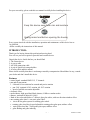
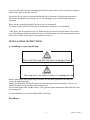
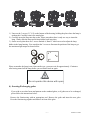
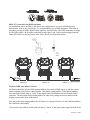
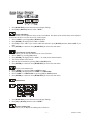
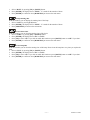
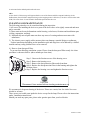
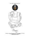
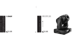
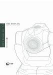
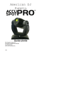
PROFESSIONAL MOVING HEAD USER’S MANUAL SPOT PRO 700 KEEP THIS MANUAL FOR FUTURE NEEDS For your own safety, please read this user manual carefully before installing the device. Keep this device away from rain and moisture ! Unplug mains lead before opening the housing. Every person involved with the installation, operation and maintenance of this device has to: -be qualified -follow carefully the instructions of this manual INTRODUCTION: Thank you for having chosen this professional moving head. You will see you have acquired a powerful and versatile device. Unpack the device. Inside the box you should find: 1. The fixture device 2. A power cable 3. An XLR connection cable 4. A pair of Quick-lock omega holders 5. A safety cable and this manual Please check carefully that there is no damage caused by transportation. Should there be any, consult your dealer and don’t install this device. Features • • • • • • • control signal: standard DMX-512, 17 channels pan and tilt movement: 8 bit and 16 bit resolution for smooth and precise motion pan: 540° (optional: 630°) rotation, tilt: 265° rotation speed of pan/tilt movement adjustable electronic focus strobe/shutter: high speed dual-blade shutter, 0-10Hz or random strobe dimmer: mechanical adjust 0%~100% Both of the colors wheels have 7 dichroic glass plus white, with two direction rainbow effect. one rotating gobo wheel + one static gobo wheel: slot in & out gobos system for rotating gobo wheel. rotating gobo wheel has 6 speed adjustable rotating gobos plus open, rainbow effect static gobo wheel has 7 fixed gobos plus open, rainbow effect gobo shaking and gobo indexing - 1 - XM010-V1.4-NR • Step zoom function with 18°、22°、26° lens can be selected. • Iris from 5%~100% with pulse iris effect. • prism: 3- face speed adjustable prism rotates in two directions with 16 prism macro effect • auto-program: 8 pre-built programs can be selected • display: can turn 180° reverse to meet mounting location requires • local or remote resetting • lamp switches ON/OFF locally or remote, motor reset • auto test for all functions • value of each DMX-channel can be displayed • save program: Edit and save the program to the incorporated EEPROM through the front control panel or external controller; can save maximum 48 scenes, and run the saved program by the “run” menu from the front control panel SAFETY INSTRUCTIONS ! ! CAUTION Be very careful during installation. Since you will be working with a dangerous voltage you can suffer a life-threatening electric shock when touching live wires. ! ! ! This device has left the factory in perfect condition. In order to maintain this condition and to ensure a safe operation, it is absolutely necessary for the user to follow the safety instructions and warning notes written in this user manual. IMPORTANT Damages caused by the disregard of this user manual are not subject to warranty. The dealer will not accept liability for any resulting defects or problems. If the device has been exposed to temperature changes due to environmental changes, do not switch it on immediately. The arising condensation could damage the device. Leave the device switched off until it has reached room temperature. This device falls under protection-class I. Therefore it is essential that the device be earthed. The electric connection must carry out by qualified person. If the external flexible cable or cord of this luminaire is damaged, it shall be exclusively replaced by the manufacturer or his service agent or a similar qualified person in order to avoid a hazard. Make sure that the available voltage is not higher than stated at the end of this manual. Make sure the power cord is never crimped or damaged by sharp edges. If this would be the case, - 2 - XM010-V1.4-NR replacement of the cable must be done by an authorized dealer. Always disconnect from the mains, when the device is not in use or before cleaning it. Only handle the power cord by the plug. Never pull out the plug by tugging the power cord. During initial start-up some smoke or smell may arise. This is a normal process and does not necessarily mean that the device is defective, it should decrease gradually. CAUTION Never touch the device during operation! The housing may heat up CAUTION Never look directly into the light source, as sensitive persons may suffer an epileptic shock. Please be aware that damages caused by manual modifications to the device are not subject to warranty. Keep away from children and non-professionals. GENERAL GUIDELINES This device is a lighting effect for professional use on stages, in discotheques, theatres, etc. This fixture is only allowed to be operated with the max alternating current which stated in the technical specifications in the last page of this manual, the device was designed for indoor use only. Lighting effects are not designed for permanent operation. Consistent operation breaks may ensure that the device will serve you for a long time without defects. Do not shake the device. Avoid brute force when installing or operating the device. While choosing the installation-spot, please make sure that the device is not exposed to extreme heat, moisture or dust. The minimum distance between light-output from the projector and the illuminated surface must be more than 0,5 meter. Always fix the fixture with an appropriate safety cable if you use the clamp to hang up the fixture. When fixing the device on a raised-from-the- ground support, be sure to use no less than screws and nuts of M10 x 25 mm and insert them in the pre-arranged screw holes in the base of the fixture. - 3 - XM010-V1.4-NR If you use the quick lock cam in hanging up the fixture, please make sure the 4 quick lock fasteners turned in the quick lock holes correctly. Operate the device only after having familiarized with its functions. Do not permit operation by persons not qualified for operating the device. Most damages are the result of unprofessional operation. Please use the original packaging if the device is to be transported. For safety reasons, please be aware that all modifications on the device are forbidden. If this device will be operated in any way different to the one described in this manual, the product may suffer damages and the guarantee becomes void. Furthermore, any other operation may lead to short-circuit, burns, electric shock, lamp explosion, crash, etc. INSTALLATION INSTRUCTIONS a) Installing or replacing the lamp CAUTION Only install the lamp with the device unplugged from the mains. CAUTION The lamp has to be replaced when it is damaged or deformed. Before replacing the lamp let the lamp cool down, because during operation, the lamp can reach very high temperature. During the installation of halogen lamps do not touch the glass bulbs bare handed. Always use a cloth to handle the lamps during insertion and removal. Do not install lamps with a higher wattage. They generate higher temperatures than which the device was designed for. For the installation, you need one Philips MSR 700/2 lamp Procedures: - 4 - XM010-V1.4-NR 1) Unscrew the 3 screws (X, Y, Z) on the bottom of the housing, holding the plate where the lamp is underneath. Carefully remove the metal plate. 2) Carefully insert the lamp into the socket. Please remember there is only one way to insert the lamp. Gently slide the lamp and its lamp holder back into place. 3) On the access plate there are 3 screws marked A, Band C. which are used to adjust the lamp holder in the lamp housing. You can adjust the 3 screws to fine-turn the position of the lamp to get the maximum light output as shown below. Y X Z Please remember the lamp is not a hot-restrike type, you must wait for approximately 15 minutes after having turned off the lamp before you can turn it back on again. ! CAUTION Do not operate this device with open cover b) Inserting/Exchanging gobos If you wish to use other forms and patterns as the standard-gobos, or if gobos are to be exchanged, please follow the instructions below: Remove the fixation-ring with an appropriate tool. Remove the gobo and insert the new gobo. Press the fixation-ring together and insert it in front of the gobo. - 5 - XM010-V1.4-NR c) Mounting the device ! CAUTION Please consider the EN 60598-2-17 and the other respective national norms during installation. The installation must only be carried out by a qualified person. ! The ! installation of the effect has to be built and constructed in a way that it can hold 10 times the weight for 1 hour without any harming deformation. The installation must always be secured with a secondary safety attachment, e.g. an appropriate safety cable. Never stand directly below the device when mounting, removing or servicing the fixture. The operator has to make sure the safety relating and machine technical installations are approved by an expert before taking the device into operation for the first time. These installations have to be approved by a skilled person once a year. ! CAUTION Before taking into operation for the first time, the installation has to be approved by an expert. Cautions: The effect should be installed outside areas where persons may reach it, walk by or be seated. - 6 - XM010-V1.4-NR ! CAUTION When installing the device, make sure there is no highly inflammable material within a distance of min. 0,5m Overhead mounting requires extensive experience, including amongst others calculating working load limits, installation material being used, and periodic safety inspection of all installation material and the device. If you lack these qualifications, do not attempt the installation yourself. Improper installation can result in bodily injury. ! CAUTION The electric connection must only be carried out by a qualified electrician. Before mounting make sure that the installation area can hold a minimum point load of 10 times the device’s weight. Connect the fixture to the mains with the power plug. - 7 - XM010-V1.4-NR Installation via the Omega holders Screw one clamp each via a M12 screw and nut onto the Omega holders. Insert the quick-lock fasteners of the first Omega holder into the respective holes on the bottom of the device. Tighten the quick-lock fasteners fully clockwise. Install the second Omega holder. Pull the safety-rope through the holes on the bottom of the base and over the trussing system or a safe fixation spot. Insert the end in the carabine and tighten the safety screw. DMX-512 control connection Connect the provided XLR cable to the female 3-pin XLR output of your controller and the other side to the male 3-pin XLR input of the moving head. You can chain multiple Moving head together through serial linking. The cable needed should be two core, screened cable with XLR input and output connectors. Please refer to the diagram below. - 8 - XM010-V1.4-NR DMX-512 connection with DMX terminator For installations where the DMX cable has to run a long distance or is in an electrically noisy environment, such as in a discotheque, it is recommended to use a DMX terminator. This helps in preventing corruption of the digital control signal by electrical noise. The DMX terminator is simply an XLR plug with a 120 Ω resistor connected between pins 2 and 3,which is then plugged into the output XLR socket of the last fixture in the chain. Please see illustrations below. Address 35 Address 18 Address 1 Projector DMX start address selection All fixtures should be given a DMX starting address when using a DMX signal, so that the correct fixture responds to the correct control signals. This digital starting address is the channel number from which the fixture starts to “listen” to the digital control information sent out from the DMX controller. The allocation of this starting address is achieved by setting the correct number on the display located on the base of the device. You can set the same starting address for all fixtures or a group of fixtures, or make different address for each fixture individually. If you set the same address, all the units will start to “listen” to the same control signal from the same - 9 - XM010-V1.4-NR channel number. In other words, changing the settings of one channel will affect all the fixtures simultaneously. If you set a different address, each unit will start to “listen” to the channel number you have set, based on the quantity of control channels of the unit. That means changing the settings of one channel will affect only the selected fixture. In the case of the spot head, which is a 17 channel fixture, you should set the starting address of the first unit to 1, the second unit to 18 (17 + 1), the third to 35 (18 + 17), and so on. Note: After switching on, the machine will automatically detect whether DMX 512 data is received or not. If the data is received, the display will show "A.001" with the actually set address. If there is no data received at the DMX-input, the display flashes "A001" with the actually set address. This situation can occur if: - the 3 PIN XLR plug (cable with DMX signal from controller) is not connected with the input of the machine. - the controller is switched off or defective, if the cable or connector is defective or the signal wires are swap in the input connector. Control Board The Control Board offers several features: you can simply set the starting address, switch on and off the lamp, run the pre-programmed program or make a reset. The main menu is accessed by pressing the Mode/esc-button until the display starts flashing. Browse through the menu by pressing the Up-button or Down-button. Press the Enter-button in order to select the desired menu. You can change the selection by pressing the Up-button or Down-button. Confirm every selection by pressing the Enter-button. You can leave every mode by pressing the Mode/esc-button. The functions provided are described in the following sections. - 10 - XM010-V1.4-NR Main menu Sub. menu ADDR 0 MODE Extension VALU SLAV A001~AXXX (AXXX) ON/OFF (SLAV) EBOC ON/OFF AUTO ALON MAST (AU-A) (AU-M) ALON (SO-A) MAST (SO-M) RUN SOUN 1 2 3 LAMP SET ADJU 5 TIME EDIT D-00 (DXXX) Function DMX address setting Slave setting Change DMX address via external controller Automatic Run in Stand Alone Automatic Run as Master Sound-controlled Run in Stand Alone Sound-controlled Run as Master Display the DMX 512 value of each channel Reverse display VALU D–XX DISP RDIS ON/OFF ON/OFF OPEN LAAU CLDI ON/OFF ON/OFF ONLI ON/OFF Lamp on/off via controller DELA D–XX D-05 Delay lamp on RPAN ON/OFF Pan Reverse RTIL 16BI DEGR DIMM ON/OFF ON/OFF 630/540 Slow/Fast Tilt Reverse Switch 16 bit/8 bit Pan degree select Dimmer speed MIC AUTO FANS SPEE REST LODA VER LADJ TEST M-XX Clos/Hold/Auto/Audi HIGH/AUTO SP-1/SP-2 Mic sensitivity No DMX Status Fan’s mode select Movement Mode Select Reset Restore factory settings Software version Lamp adjustment Test function of each channel ON/OFF V-1.0~V-9.9 ON/OFF T–01~T–30 MATI LATI 0000~9999(hours) Lamp running time CLMT ON/OFF Clear fixture time CLLT ON/OFF Clear lamp time STEP S–01 ~S–48 Steps of Program Run REC. RE.XX SC01 ~ SC48 CXXX XXXX(-128~127) Shut off LED display Lamp on/off Lamp automated on with power CODE CH01~CH30 0000~9999(hours) WHEL 4 Display Fixture code *code is “C050” Motor Fix Fixture running time Auto Save Scene C–01~C–30 0 1 XX(00~FFH) 3 0 XX(00~FFH) Edit the channels of each scene TIME T XXX(001~999) Time for each scene CNIN ON/OFF Edit program via controller - 11 - XM010-V1.4-NR Default settings shaded. Note: By default setting, the lamp is not ignited with power on. Lamp can be turned on via DMX controller. Main functions: - Main menu 0 1. 2. 3. Press [MODE/ESC] to enter the main menu "MODE" (display flashing) Press [ENTER] and select "ADDR", “RUN” or "DISP" by pressing [UP] or [DOWN] button. Press [ENTER] for selecting the desired sub menu. - DMX address setting, Slave setting - DMX address setting With this function, you can adjust the desired DMX-address via the Control Board. 1. Select “ VALU” by pressing [UP] or [DOWN] button. 2. Press [ENTER], adjust the DMX address by pressing [UP] or [DOWN] button. 3. Press [ENTER] to confirm or pressing [MODE/ESC] to return to main menu. - Slave setting With this function, you can define the device as slave. 1. Select “SLAV” by pressing [UP] or [DOWN] button. 2. Press [ENTER], the display shows “ON” or “OFF”. 3. Press [UP] to select “ON” if you wish to enable this function or press [DOWN] to select “OFF” if you don’t. 4. Press [ENTER] to confirm or press [MODE/ESC] to return to main menu. -DMX address setting via controller With this function, you can adjust the desired DMX-address via an external controller. This function can only be activated when the DMX-value of all other channels is set to "0" on the controller. Select “EBOC” by pressing [UP] or [DOWN]. Press [ENTER], the display shows “ON” or “OFF”. - 12 - XM010-V1.4-NR Press [UP] to select “ON” if you wish to enable this function or [DOWN] to select “OFF” if you don’t. Press [MODE/ESC] to confirm. Press [ENTER] in order to return to the main menu. On the controller, set the DMX-value of channel 1 to "7". Set the DMX-value of channel 2 to "7"or "8". When set to "7" you can adjust the starting address between 1 and 255. When set to "8" you can adjust the starting address between 256 and 511. Set the DMX-value of channel 3 to the desired starting address. If you want to set the starting address to 57, set channel 1 to "7", channel 2 to "7" and channel 3 to "57". If you want to set the starting address to 420, set channel 1 to "7", channel 2 to "8" and channel 3 to "164" (256+164=420). Wait for approx. 20 seconds and the unit will carry out a reset. After that, the new starting address is set. - Program Run, Master setting With the function "RUN", you can run the internal program. You can set the number of steps under Step. You can edit the individual scenes under Edit. You can run the individual scenes either automatically (AUTO), i.e. with the adjusted Step-Time or sound-controlled (SOUN). The selection "ALON" means Stand Alone-mode and "MAST" that the device is defined as master. 1. 2. 3. 4. Select "AUTO" or "SOUN" by pressing [UP] or [DOWN] button. Press [ENTER] for selecting the desired extension menu. Select "ALON" or "MAST" by pressing [UP] or [DOWN] button. Press [ENTER] to confirm or Press [MODE/ESC] to return to the main menu. - Display the DMX-value, Reverse display, Shut off LED display - Display the DMX 512 value of each channel With this function you can display the DMX 512 value of each channel. 1. Select "VALU" by pressing [UP] or [DOWN] button. 2. Press [ENTER] to confirm; the display shows“D-00”. In this setting, the DMX-adjustment of every channel will be displayed. 3. Press [UP] or [DOWN] button in order to select the desired channel. If you select “D-14” the display will only show the DMX-value of the 14th channel. 4. Press [ENTER] to confirm or Press [MODE/ESC] to return to the main menu. 5. The display shows "D- XX”, “X” stands for the DMX-value of the selected channel. - Reverse display With this function you can rotate the display by 180°. 1. Select "RDIS" by pressing [UP] or [DOWN] button. - 13 - XM010-V1.4-NR 2. 3. 4. Press [ENTER], the display shows “ON” or “OFF”. Press [UP] to select “ON” if you wish to enable this function or press [DOWN] button to “OFF” if you don’t; the display will rotate by 180°. Press [ENTER] to confirm or Press [MODE/ESC] to return to the main menu. - Shut off LED display With this function you can shut off the LED display after 2 minutes. 1. Select "CLDI" by pressing [UP] or [DOWN] button. 2. Press [ENTER], the display shows “ON” or “OFF”. 3. Press [UP] to select “ON” if you wish to enable this function or press [DOWN] button to “OFF” if you don’t. 4. Press [ENTER] to confirm or Press [MODE/ESC] to return to the main menu. - Main menu 1 1. Press [MODE/ESC] to enter the main menu (display flashing). 2. Press [UP] or [DOWN] button to select “LAMP”. - Lamp on/off With this function you can switch the lamp on or off via the Control Board. 1. Select “OPEN” by pressing [UP] or [DOWN] button. 2. Press [ENTER], the display shows “ON” or “OFF”. 3. Press [UP] to select “ON” if you wish to enable this function or press [DOWN] button to “OFF” if you don’t. 4. Press [ENTER] to confirm or Press [MODE/ESC] to return to the main menu. - Lamp automated on with power. With this function you can set the lamp be ignited or not when the fixture is power on. 1. Select “LAAU” by pressing [UP] or [DOWN] button. 2. Press [ENTER], the display shows “ON” or “OFF”. 3. Press [UP] to select “ON” if you wish to enable this function or press [DOWN] button to “OFF” if you don’t. 4. Press [ENTER] to confirm or Press [MODE/ESC] to return to the main menu. - Lamp on/off via external controller With this function you can switch the lamp on or off via an external controller. 1. Select “ONLI” by pressing [UP] or [DOWN] button. 2. Press [ENTER], the display shows “ON” or “OFF”. 3. Press [UP] to select “ON” if you wish to enable this function or press [DOWN] button to “OFF” if you don’t. 4. Press [ENTER] to confirm or Press [MODE/ESC] to return to the main menu. - Delay lamp on With this function you can delay the lamp ignition. 1. Select “DELA” by pressing [UP] or [DOWN] button. - 14 - XM010-V1.4-NR 2. Press [ENTER], the display shows “ON” or “OFF”. 3. Press [UP] to select “ON” if you wish to enable this function or press [DOWN] button to “OFF” if you don’t. 4. Press [ENTER] to confirm or Press [MODE/ESC] to return to the main menu. - Main menu 2 1. 2. Press [MODE/ESC] to enter the main menu (display flashing). Press [UP] or [DOWN] button. to select “SET”. - Pan Reverse With this function you can reverse the Pan-movement. 1. Select “RPAN” by pressing [UP] or [DOWN] button. 2. Press [ENTER], the display shows “ON” or “OFF”. 3. Press [UP] to select “ON” if you wish to enable this function or press [DOWN] button to “OFF” if you don’t. 4. Press [ENTER] to confirm or Press [MODE/ESC] to return to the main menu. - Tilt Reverse With this function you can reverse the Tilt-movement. 1. Select “RTIL” by pressing [UP] or [DOWN] button. 2. Press [ENTER], the display shows “ON” or “OFF”. 3. Press [UP] to select “ON” if you wish to enable this function or press [DOWN] button to “OFF” if you don’t. 4. Press [ENTER] to confirm or Press [MODE/ESC] to return to the main menu. - Switch 16 bit/8 bit With this function you can switch the device from 16 bit to 8 bit resolution. 1. Select “16BI” by pressing [UP] or [DOWN] button. 2. Press [ENTER], the display shows “ON” or “OFF”. 3. Press [UP] to select “ON” if you wish to enable this function or press [DOWN] button to “OFF” if you don’t. 5. Press [ENTER] to confirm or Press [MODE/ESC] to return to the main menu. - Pan degree select With this function you can select pan angle 6300 or 5400. 1. Select “DEGR” by pressing [UP] or [DOWN] button. 2. Press [ENTER], the display shows “630” or “540”. 3. Press [UP] to select “630” or press [DOWN] button to select“540”. 4. Press [ENTER] to confirm or Press [MODE/ESC] to return to the main menu. - Dimmer speed select With this function you can select dimmer speed “slow” and “fast”. 1. Select “DIMM” by pressing [UP] or [DOWN] button. 2. Press [ENTER], the display shows “SLOW” or “FAST”. 3. Press [UP] or [DOWN] button to select “SLOW” or “FAST”. 4. Press [ENTER] to confirm or Press [MODE/ESC] to return to the main menu. - 15 - XM010-V1.4-NR - Mic sensitivity With this function you can adjust the sensitivity of the microphone. 1. Select “MIC” by pressing [UP] or [DOWN] button. 2. Press [ENTER], the display shows “M-XX”, “XX” stands for the number from 0 to 99. 3. Press [ENTER] to confirm or Press [MODE/ESC] to return to the main menu. -Automatic Run by no DMX With this function you can automatic run the device by no DMX. 1. Select “AUTO” by pressing [UP] or [DOWN] button. 2. Press [ENTER], the display shows “CLOS”, “HOLD”, “AUTO” or “AUDI”. 3. Press [UP] or [DOWN] button to select “CLOS”, “HOLD”, “AUTO” or “AUDI”, the default is “HOLD”. 4. Press [ENTER] to confirm or Press [MODE/ESC] to return to the main menu. - Fan’s mode select With this function you can select the Fan’s mode. 1. Select “FANS” by pressing [UP] or [DOWN] button. 2. Press [ENTER], the display shows “HIGH” or “AUTO”. 3. Select “HIGH” or “AUTO” by pressing [UP] or [DOWN] button. 4. Press [ENTER] to confirm or Press [MODE/ESC] to return to the main menu. - Movement mode select With this function you can select the movement mode. 1. Select “SPEE” by pressing [UP] or [DOWN] button. 2. Press [ENTER], the display shows “SP-1” or “SP-2”. 3. Select “SP-1” or “SP-2” by pressing [UP] or [DOWN] button. 4. Press [ENTER] to confirm or Press [MODE/ESC] to return to the main menu.. - Reset With this function you can reset the device via the Control Board. 1. Select “REST” by pressing [UP] or [DOWN] button. 2. Press [ENTER] to reset or Press [MODE/ESC] to return to the main menu. - Restore factory settings With this function you can restore the factory settings of the device. All settings will be set back to the default values (shaded). Any edited scenes will be lost. 1. Select “LODA” by pressing [UP] or [DOWN] button. 2. Press [ENTER], the display shows “ON” or “OFF”. 3. Press [UP] to select “ON” if you wish to enable this function or press [DOWN] button to “OFF” if you don’t. 4. Press [ENTER] to confirm or Press [MODE/ESC] to return to the main menu. - Software version With this function you can display the software version of the device. 1. Select “VER” by pressing [UP] or [DOWN] button. 2. Press [ENTER], The display will show “V-XX”, "XX" stands for the version number, such as the display may also show,"V-2.0","V-9.9"etc. 3. Press [ENTER] to confirm or Press [MODE/ESC] to return to the main menu. - Main menu 3 - 16 - XM010-V1.4-NR 1. Press [MODE/ESC] to enter the main menu (display flashing). 2. Press [UP] or [DOWN] button to select “ADJU”. - Lamp adjustment With this function you can adjust the lamp via the Control Board. The shutter opens and the lamp can be adjusted. In this mode, the device will not react to any control signal. 1. Select “LADJ” by pressing [UP] or [DOWN] button. 2. Press [ENTER], the display shows “ON” or “OFF”. 3. Press [UP] to select “ON” if you wish to enable this function or press [DOWN] button to select “OFF” if you don’t. 4. Press [ENTER] to confirm or Press [MODE/ESC] to return to the main menu. - Test function of each channel With this function you can test each channel on its (correct) function. 1. Select “TEST” by pressing [UP] button. 2. Press [ENTER], the display shows “T-XX”, “X” stands for the channel number. 3. The current channel will be tested. 4. Select the desired channel by pressing [UP] or [DOWN] button. 5. Press [ENTER] to confirm or Press [MODE/ESC] to return to the main menu. 1. 2. 4. 5. - Fixture code and motor fix Select “WHEL” by pressing [UP] or [DOWN] button. Press [ENTER], the display shows “CODE” or “CH01-CH30”. Select “CODE” or “CH01-CH30” by pressing [UP] or [DOWN] button. Press [ENTER] to confirm or Press [MODE/ESC] to return to the main menu. - Main menu 4 1. Press [MODE/ESC] to enter the main menu (display flashing). 2. Press [UP] or [DOWN] button to select “TIME”. - Fixture running time With this function you can display the running time of the device. - 17 - XM010-V1.4-NR 1. 2. 3. Select “MATI” by pressing [UP] or [DOWN] button. Press [ENTER], the display shows “XXXX”, “X” stands for the number of hours. Press [ENTER] to confirm or Press [MODE/ESC] to return to the main menu. - Lamp running time With this function you can display the running time of the lamp. 1. Select “LATI” by pressing [UP] button. 2. Press [ENTER], the display shows “XXXX”, “X” stands for the number of hours. 3. Press [MODE/ESC] to return to the main menu. - Clear fixture time With this function you can clear the running time of the device. 1. Select “CLMT” by pressing [UP] or [DOWN] button. 2. Press [ENTER], the display shows “ON” or “OFF”. 3. Press [UP] to select “ON” if you wish to enable this function or press [DOWN] button to “OFF” if you don’t. 4. Press [ENTER] to confirm or Press [MODE/ESC] to return to the main menu. - Clear lamp time With this function you can clear the running time of the lamp. Please clear the lamp time every time you replace the lamp. 1. Select “CLLT” by pressing [UP] or [DOWN] button. 2. Press [ENTER], the display shows “ON” or “OFF”. 3. Press [UP] to select “ON” if you wish to enable this function or press [DOWN] button to “OFF” if you don’t. 4. Press [ENTER] to confirm or Press [MODE/ESC] to return to the main menu. - 18 - XM010-V1.4-NR - Main menu 5 1. Press [MODE/ESC] to enter the main menu (display flashing). 2. Press [UP] or [DOWN] button to select “EDIT”. - Define the number of steps in Run With this function you can define the number of steps in the Program Run. 1. Select “STEP” by pressing [UP] or [DOWN] button. 2. Press [ENTER], the display shows “S-XX”, “X” stands for the total amount of steps you want to save, so you can call up to 48 scenes in “RUN”. For example if the “XX” is 05, it means that “RUN” will run the first 5 scenes you saved in “EDIT”. 3. Press [ENTER] to confirm or Press [MODE/ESC] to return to the main menu. -Auto Save With this function you can automatic save the number of steps in the Program Run. 1. Select “REC” by pressing [UP] or [DOWN] button. 2. Press [ENTER], the display shows “RE.XX”, “XX” stands for the number from 1 to 400. 2. Press [ENTER] to confirm or Press [MODE/ESC] to return to the main menu. - Editing the channels of the individual scenes With this function you can edit the program to be called up in Run. a) Editing via the Control Board 1. Select “SC01” by pressing [UP] or [DOWN] button. 2. Press [ENTER], the display shows “SCXX”, “X” stands for the scene no. to be edited. 3. Change the scene no. by pressing [UP] or [DOWN] button. 4. Press [ENTER], the display shows “C-X”, “X” stands for the channel no. Such as “C-01”, it means you are editing channel 1 of the selected scene. 5. Select the channel no. you would like to edit by pressing [UP] or [DOWN] button. 6. Press [ENTER] to enter editing for the selected channel, the fixture reacts to your settings. The display shows the DMX value of the edited channel. Such as “11XX”, it stands for in the channel 11 of the editing scene, the DMX value is XX, XX is a hexadecimal number value “01-FF”. 7. Adjust the desired DMX value by pressing [UP] or [DOWN] button. 8. Press [ENTER] in order to edit other channels of this scene. 9. Repeat steps 5-9 until you finish setting all the DMX values for all channels of this scene. 10. Once all the channels completed, the display will flash “TIME” 11. Press [ENTER] to edit the time needed, the display shows “TXXX” , “XXX” stands for the time needed to run the current scene, value “001-999”. E.g., “002” means you need 0.4ms (002*0.2ms) to run the current scene. Adjust the desired time by pressing [UP] or [DOWN] button. 12. Press [ENTER] to save the settings for the scene you are editing, the display will change to the next scene automatically. - 19 - XM010-V1.4-NR 13. Repeat step 3-14 to edit and other scenes, you can edit and save a maximum of 48 scenes. 14. Press [MODE/ESC] to exit. The number of steps can be defined under “STEP” and the scenes can be called up under “RUN” b) Editing via the external controller Call up the first scene in your controller now. 1. Select “SC01” by pressing [UP] or [DOWN] button. 2. Press [ENTER], the display shows “SC01”. 3. Press [ENTER], the display shows “C-01”. 4. Select "CNIN" by pressing [UP] or [DOWN] button. 5. Press [ENTER], the display shows "OFF". 6. Press [UP] or [DOWN] button .the display shows "ON". 7. Press [ENTER], the display shows "SC02". You successfully downloaded the first scene. 8. Adjust the Step-time as described above under point 12. 9. Call up the second scene in your controller now. 10. Repeat steps 5-11 until all desired scenes are downloaded. 11. Press [MODE/ESC] to exit. The number of steps can be defined under “STEP” and the scenes can be called up under “RUN” DMX channel´s functions and their values (17 DMX channels): Channel 1 - Color Wheel 1: 0-15 Open / white 16-31 Color 1 32-47 Color 2 48-63 Color 3 64-79 Color 4 80-95 Color 5 96-111 Color 6 112-127 Color 7 128-187 Forwards rainbow effect from fast to slow 188-193 No rotation 194-255 Backwards rainbow effect from slow to fast Channel 2 - Rotating gobos, cont. rotation : 0-9 Open 10-19 Rot. gobo 1 (dichroic multicolor) 20-29 Rot. gobo 2 (glass) 30-39 Rot. gobo 3 (metal) 40-49 Rot. gobo 4 (metal) 50-59 Rot. gobo 5 (metal) 60-69 Rot. gobo 6 (metal) 70-89 Gobo 1 shake slow to fast 90-109 Gobo 2 shake slow to fast 110-129 Gobo 3 shake slow to fast - 20 - XM010-V1.4-NR 130-149 Gobo 4 shake slow to fast 150-169 Gobo 5 shake slow to fast 170-189 190-255 Gobo 6 shake slow to fast Rot. gobo wheel cont. rotation slow to fast Channel 3 - Rotating gobo index, rotating gobo rotation : 0-127 Gobo indexing 128-187 Forwards gobo rotation from fast to slow 188-193 No rotation 194-255 Backwards gobo rotation from slow to fast Channel 4- Fixed Gobos : 0-13 Open/hole 14-27 Gobo 1 28-41 Gobo 2 42-55 Gobo 3 56-69 Gobo 4 70-83 Gobo 5 84-97 Gobo 6 98-111 Gobo 7 112-127 Gobo 1 shake slow to fast 128-143 Gobo 2 shake slow to fast 144-159 Gobo 3 shake slow to fast 160-175 Gobo 4 shake slow to fast 176-191 Gobo 5 shake slow to fast 192-207 Gobo 6 shake slow to fast 208-223 Gobo 7 shake slow to fast 224-255 Gobo wheel rotation from slow to fast Channel 5 - PAN movement 8bit : Channel 6 - TILT movement 8bit : Channel 7 - Speed pan/tilt movement: Max to min speed 0-225 226-235 236-245 Blackout by movement 246-255 No function Blackout by all wheel changing Channel 8- 3 facet rotating prism, Prism / Gobo macros: 0-3 Open - 21 - XM010-V1.4-NR 4-63 Forwards rotation from fast to slow 64-67 No rotation 68-127 Backwards rotation from slow to fast 128-135 Macro 1 136-143 Macro 2 144-151 Macro 3 152-159 Macro 4 160-167 Macro 5 168-175 Macro 6 176-183 Macro 7 184-191 Macro 8 192-199 Macro 9 200-207 Macro 10 208-215 Macro 11 216-223 Macro 12 224-231 Macro 13 232-239 Macro 14 240-247 Macro 15 248-255 Macro 16 Channel 9 – Focus & Zoom: 0-85 Zoom1 & Continuous adjustment from far to near 86-171 Zoom2 & Continuous adjustment from far to near 172-255 Zoom3 & Continuous adjustment from far to near Channel 10 - Shutter, strobe: 0-31 Shutter closed 32-63 No function (shutter open) 64-95 Strobe effect slow to fast 96-127 No function (shutter open) 128-159 Pulse-effect in sequences 160-191 No function (shutter open) 192-223 Random strobe effect slow to fast 224-255 No function (shutter open) Channel 11- Dimmer (intensity): Intensity 0 to 100% 0-255 Channel 12 – Iris: 0-191 Max. diameter to Min.diameter 192-223 Pulse opening fast to slow - 22 - XM010-V1.4-NR 224-255 Pulse closing slow to fast Channel 13 –Frost: 0-191 Frost 0~100% 192-223 Pulse opening fast to slow 224-254 Pulse closing slow to fast 255 100% Frost Channel 14 - Color Wheel 2 : 0-15 Open / white 16-31 Color 1 32-47 Color 2 48-63 Color 3 64-79 Color 4 80-95 Color 5 96-111 Color 6 112-127 Color 7 128-187 Forwards rainbow effect from fast to slow 188-193 No rotation 194-255 Backwards rainbow effect from slow to fast Channel 15– Lamp on/off, reset, internal programs: 0-19 Color & gobo change normal 20-29 Color change to any position 30-39 Color & gobo change to any position 40-59 Lamp on 60-79 Lamp switch off 80-99 Motor reset 100-119 Internal program 1 120-139 Internal program 2 140-159 Internal program 3 160-179 Internal program 4 180-199 Internal program 5 200-219 Internal program 6 220-239 Internal program 7 240-255 Internal program 8 Channel 16 – Pan fine 16bit Channel 17– Tilt fine 16bit - 23 - XM010-V1.4-NR ERROR MESSAGE When you turn on the fixture, it will make a reset first. The display may show “Xer” while there are problems with one or more channels. “XX” stands for channel 1,2,3,4,5,6,8,9,12,14 who has the testing sensor for positioning . For example, when the display shows “02Er”, it means there is some error in channel 2. If there are some errors on channel 1, channel 2, channel 5 at the same time, you may see the error message “01Er”, “02Er”,”05Er” flash repeated for 5 times, and then the fixture will generate a reset signal, all the stepper reset. If the fixture remain error message after performing reset more than 3 times, it will detect whether the fixture has more than 3 errors. If the fixture has more than 3 errors (including 3 errors), all the channels can not work properly; but if the fixture has less than 3 errors, only the channels which have errors can not work properly, others can work as usual. 01Er: (Color-wheel 1 error) This message will appear after the reset of the fixture if the magnetic-indexing circuit malfunctions (sensor failed or magnet missing) or the stepping-motor is defective (or its drive circuit on the main PCB). The color wheel is not located in the default position after the reset. 02Er: (Rotating gobo-wheel error ) This message will appear after the reset of the fixture if the magnetic-indexing circuit malfunctions (sensor failed or magnet missing) or the stepping-motor is defective (or its drive circuit on the main PCB). The rotating gobo-wheel is not located in the default position after the reset. 03Er: (Gobo rotating error) This message will appear after the reset of the fixture and if the magnetic-indexing circuit malfunctions (sensor failed or magnet missing) or the stepping-motor is defective (or its driver circuit on the main PCB). The rotating gobo is not located in the default position after the reset. 04Er: (Fix Gobo-wheel error) This message will appear after the reset of the fixture if the magnetic-indexing circuit malfunctions (sensor failed or magnet missing) or the stepping-motor is defective (or its drive circuit on the main PCB). The fix gobo wheel is not located in the default position after the reset. 05Er: (PAN-yoke movement error) This message will appear after the reset of the fixture if the yoke’s magnetic-indexing circuit malfunction (sensor failed or magnet missing) or the stepping-motor is defective (or its driving IC on the main PCB). The yoke is not located in the default position after the reset. 06Er: (TILT-head movement error) This message will appear after the reset of the fixture if the head’s magnetic-indexing circuit malfunctions (sensor failed or magnet missing) or the stepping-motor is defective (or its driving IC on the main PCB). The head is not located in the default position after the reset. 08Er: (Prism-wheel error) This message will appear after the reset of the fixture and if the magnetic-indexing circuit malfunctions (sensor failed or magnet missing) or the stepping-motor is defective (or its driver circuit on the main PCB). The rotating gobo is not located in the default position after the reset. 09Er: (Focus or zoom error) This message will appear after the reset of the fixture and if the magnetic-indexing circuit malfunctions (sensor failed or magnet missing) or the stepping-motor is defective (or its driver circuit on the main PCB). The focus is not located in the default position after the reset. 12Er: (Iris error) This message will appear after the reset of the fixture and if the magnetic-indexing circuit malfunctions (sensor failed or magnet missing) or the stepping-motor is defective (or its driver circuit on the main PCB). The iris - 24 - XM010-V1.4-NR is not located in the default position after the reset. 14Er: (Color wheel 2) This message will appear after the reset of the fixture and if the magnetic-indexing circuit malfunctions (sensor failed or magnet missing) or the stepping-motor is defective (or its driver circuit on the main PCB). The color wheel 2 is not located in the default position after the reset. CLEANING AND MAINTENANCE The following points have to be considered during the inspection: 1) All screws for installing the devices or parts of the device have to be tightly connected and must not be corroded. 2) There must not be any deformations on the housing, color lenses, fixations and installation spots (ceiling, suspension, trussing). 4) Mechanically moved parts must not show any traces of wearing and must not rotate with unbalances. 5) The electric power supply cables must not show any damage, material fatigue or sediments. Further instructions depending on the installation spot and usage have to be adhered by a skilled installer and any safety problems have to be removed. 6) How to clean dust-proof filter: To prevent from blooking ventilation system. Please clean the dust-proof filter termly. the clean procedure is shown as bellow: (three months per clean time). Step 1: Unscrew the fixation screws of the housing cover. Step 2: Remove the housing cover. Step 3: Remove the dust protection filters and clean them. Step 4: Replace the dust protection filters in the housing and tighten the fixation screws. Step 5: Replace the housing cover and tighten the fixation screws. ! CAUTION Disconnect from mains before starting maintenance operation. We recommend a frequent cleaning of the device. Please use a moist, lint- free cloth. Never use alcohol or solvents. There are no serviceable parts inside the device except for the lamp. Please refer to the instructions under “Installation instructions”. Should you need any spare parts, please order genuine parts from your local dealer. - 25 - XM010-V1.4-NR TECHNICAL SPECIFICATIONS Power supply: □100VAC,50Hz;□120VAC, 50Hz;□208VAC, 50Hz;□220VAC,50Hz;□230VAC,50Hz;□240VAC, 50Hz; □100VAC,60Hz;□120VAC,60Hz; □208VAC, 60Hz;□220VAC,60Hz;□230VAC,60Hz;□240VAC,60Hz; Power consumption: max. 950W Lamp: PHILIPS MSR 700/2 Packing dimensions: 72 x 56 x 60 cm Net weight: 37.5KG Gross weight: 44.5KG Remark: errors and omissions for every information given in this manual excepted. All information is subject to change without prior notice. - 26 - XM010-V1.4-NR