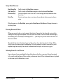
1
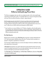
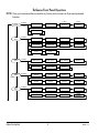
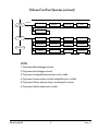
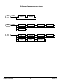
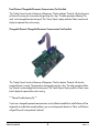
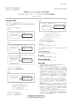
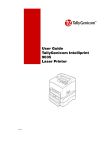
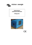
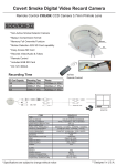
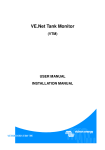
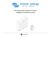
INTELLIGENT ENERGY / POWER METER
OPERATING GUIDE
VERSION 3 MAY, 2013
For the EnGenius User Manual, visit www.kele.com/engenius and click on the “Related Documents” tab.
Operating Guide
EnGenius Intelling Energy/Power Meter
The EnGenius energy/power meter comes with many configuration options which can be viewed/changed
using the front panel LCD display and keys. This guide will explain how to navigate and change those configuration items. Physical installation of the meter is covered in a separate document.
All of the configuration options described in this document may also be viewed and changed using the
EnGenius Desktop Software package and a programming cable which plugs into the meter’s Data Port.
The Desktop Software and programming cable may also be used to upgrade the EnGenius firmware at any
time. This allows the user to add new features to existing meters installed in the field.
** If you have the low-cost version of EnGenius (no LCD display, no keypad) you will not be able to perform
the view/change actions described in this document. You must use the EnGenius Desktop Software package instead. However, this document will still provide valuable background reference material as to how the
EnGenius configuration options work.
Run Mode Operation
When the meter is powered up, it goes to Run Mode where measurements are taken and displayed on the
LCD. Only the measurements enabled for display will be shown. The choice of which measurements are
displayed is configurable as explained later in this document.
The measurements enabled for display may auto-rotate on the display if that feature is enabled (also configurable, explained later in this document).
In Run Mode the left-right keys may be used to select the measurement desired for display. If auto-rotate is
turned off, the selected measurement will stay on the display indefinitely. If auto-rotate is turned on, after 10
minutes of no left-right key activity the auto-rotate feature will start again.
To exit Run Mode and go to Setup Mode, press the Main Menu or Sub Menu key. Operation of Setup Mode
is described in the following pages.
EnGenius Operating Guide
1
VERSION 3 May, 2013
EnGenius Front Panel Operation
NOTE:Once you have entered the password for any branch you have access to all password-protected
branches.
CLEAR
REGISTERS
PASSWORD
REQUIRED
✳ NOTE 5
✳ NOTE 5
PEAK KWH
EXTERNAL
COUNTER #1
EXTERNAL
COUNTER #2
PWRSYS TYPE
SYSTEM FS VOLTS
SYSTEM FS AMPS
CT TYPE
5A CT CALNUMS
WINDOW PERIOD
VOLT-AMP MATCH
CT POLARITIES
EXTERNAL INPUT
#1 TYPE
EXTERNAL INPUT
#2 TYPE
✳ NOTE 4
✳ NOTE 4
CONTACT OUTPUT1
CONTACT OUTPUT2
MIN PULSEWIDTH
KWH/PULSE
LOW VOLTS
ALARM THRESHOLD
UNBAL VOLTS
ALARM THRESHOLD
MA OUTPUT
PROTOCOL
PROTOCOL
DEPENDENT
PROTOCOL
DEPENDENT
PROTOCOL
DEPENDENT
PROTOCOL
DEPENDENT
PROTOCOL
DEPENDENT
PROTOCOL
DEPENDENT
PROTOCOL
DEPENDENT
NAME TAG
DISPLAY ITEMS
DISPLAY ACTION
PASSWORD
SET DEFAULTS
SET TIME
SET DATE
ACTIVATE
DATALOGGER
LOGGER STATE
SET LOGGER
PARAMETERS
SET LOGGER
SAMPLE TIMES
CALCULATE LOG
CAPACITY
CONTACT KELE
CONTACT KELE 2
METER SN
FIRMWARE VER
WIRING CONFIG
2DATE & TIME
PEAK KW
TIMESTAMP
PEAK KW CLEARED
TIMESTAMP
TOTALS CLEARED
TIMESTAMP
COMM OPTION
CELL SIGNAL
LOGGER STATUS
KWH/KVARH/KVAH
DATA LOGGER
✳ NOTE 2
CONFIG
INPUTS
CONFIG
OUTPUTS
CONFIG
COMMS
PASSWORD
REQUIRED
PASSWORD
REQUIRED
PASSWORD
REQUIRED
✳ NOTE 3
CONFIG
OTHER
~~
~~
✳
CONFIG
LOGGER
NOTE 2
PASSWORD
REQUIRED
✳ NOTE 1
PASSWORD
REQUIRED
READ LOG ENTRY
ABOUT
EnGenius Operating Guide
RUN & DISPLAY
VERSION 3 May, 2013
✳ NOTE 3
PROTOCOL
DEPENDENT
CONFIG
OTHER
~~
✳
PROTOCOL
DEPENDENT
NAME
TAG
ITEMS
DISPLAY ACTION
EnGenius
Front
PanelDISPLAY
Operation
(continued)
PASSWORD
REQUIRED
~~
CONFIG
LOGGER
NOTE 2
PROTOCOL
DEPENDENT
PASSWORD
REQUIRED
PROTOCOL
DEPENDENT
PASSWORD
SET DEFAULTS
SET TIME
SET DATE
ACTIVATE
DATALOGGER
LOGGER STATE
SET LOGGER
PARAMETERS
SET LOGGER
SAMPLE TIMES
CALCULATE LOG
CAPACITY
CONTACT KELE
CONTACT KELE 2
METER SN
FIRMWARE VER
WIRING CONFIG
DATE & TIME
PEAK KW
TIMESTAMP
PEAK KW CLEARED
TIMESTAMP
TOTALS CLEARED
TIMESTAMP
COMM OPTION
CELL SIGNAL
LOGGER STATUS
✳ NOTE 6
✳ NOTE 2
READ LOG ENTRY
ABOUT
RUN & DISPLAY
NOTES:
1. Only present before datalogger activated.
2.Only present after datalogger activated.
3.Only present if configurable communications card is installed.
4.Only present if communications card with configurable inputs is installed.
5.Only present if Note 4 and external inputs are configured as counters.
6.Only present if cellular modem card is installed.
EnGenius Operating Guide
3
VERSION 3 May, 2013
EnGenius Communications Menus
CONFIG
COMMS
PASSWORD
CONFIG
COMMS
PASSWORD
REQUIRED
REQUIRED
PROTOCOL =
METASYS N2
NWK ADDRESS
PROTOCOL =
MODBUS
NWK ADDRESS
PARITY & STOP
BAUD RATE
PROTOCOL =
BACNET
NETWORK
DEVICE NAME
NWK ADDRESS
BAUD RATE
MAX NUMBER
OF MASTERS
DEVICE INSTANCE
NUMBER
NETWORK
METER CONFIG
RETURN DATA
ORDER
CONFIG
COMMS
PASSWORD
REQUIRED
EnGenius Operating Guide
4
VERSION 3 May, 2013
Setup Mode Overview
Main Menu Key
Sub Menu Key
Direction Keys
Enter Key
Scrolls through the Main Menu categories.
Scrolls through the Sub Menu categories under the selected Main Menu.
Used to change the value of an item or scroll through possible predefined values
for an item.
Activates sub-menu items, saves item value or selection choice, executes chosen
action.
When the meter is in the Run Mode, pressing either Main Menu or Sub Menu will change the meter to
the Setup Mode.
Entering Numerical Values
Wherever numerical values are to be entered, the display will prompt for the value with a series of dots
showing how many digits are required. If the value you want to enter is less than the full number of digits,
enter leading zeros. For example, if the display shows ….. (five dots) but you want to enter the value “150”
then enter “00150.”
The right-left keys select the digit to be set and the up-down keys select the value for the digit. When
all digit values have been set press the Enter key. If the value entered is invalid for some reason (out of
expected range for example), the value will be cleared from the display and you may try again.
Selecting From A List of Choices
Some sub-menus have a predefined list of possible choices rather than a numerical value to be entered.
In this case the right-left keys will allow scrolling to the desired choice. When the desired choice is displayed
on the screen, press the Enter key to save it.
EnGenius Operating Guide
5
VERSION 3 May, 2013
Password
Most Main Menu categories require a password to be entered. The password is the same for any of the
menus which require one. Once the password has been entered, all the password-protected menus become
available.
The meter ships with the default password of 1234. The password must be 4 numerical digits. The password
can be changed through the Config Other menu described below.
Saving Changes With Enter Key
When changing configuration parameters, changes are not saved until the Enter key is pressed. If you are
in the middle of changing a parameter and decide that you want to keep the existing setting, just press the
Main Menu or Sub Menu keys to back out of the change operation.
Key Inactivity Timeout
If meter is in the Setup Mode and there is no key activity for 10 minutes, the meter will automatically log
the user out and revert to the Run Mode. Changes in progress will be discarded.
EnGenius Operating Guide
6
VERSION 3 May, 2013
Main Menu Key
From the Run Mode, first press the Main Menu key until the desired category shows in the top line of the
LCD display. The Main Menu categories are:
Clear Registers
Clears all the energy totalizers and/or the peak sliding window KW. Sets the
timestamp(s) to show when the clear(s) occurred. Clears external counters if a communications card is installed with external inputs and the inputs are configured as
counters. Clears data log if Data Logger option is activated.
Config Inputs
Configures the meter input items such as power system type, full-scale volts, full-scale
amps, CT type used, sliding window KW period in minutes. Shows CT polarities and
volt-amp phase matching, and allows these to be changed or Auto-Configure to be
invoked. If communications card with external inputs is installed, configures inputs as
on/off state sensors or counters.
Config Outputs
Configures the meter output items such as output contact functions, KWH/pulse,
minimum pulse period, mA output function.
Config Comms
Configures communications options for an installed communications card.
Options presented are dependent on the type of communications card installed.
NOTE: if no communications card is present, this category will not show up in the
display.
Config Other
Configures name tag, measurements to display, display action in Run Mode. Allows changing password. Allows setting all options to default values. Allows setting
EnGenius realtime clock’s time and date values. Allows activation of the Data Logger
option if currently not activated (Activation Code required).
About
Provides useful information such as meter serial number, firmware version, Kele
phone number and website URL. Shows whether meter inputs were Manual or
Auto-Configured. Displays timestamps of when Peak KW occurred, Peak KW was
cleared, and when totalizers were cleared. Displays communications option (if any)
installed. Displays cellular signal strength (if cellular modem option installed).
Displays data logger status (if Data Logger option is activated).
Run & Display
Exits the Setup Mode and puts meter back into Run Mode.
EnGenius Operating Guide
7
VERSION 3 May, 2013
Sub Menu Key
The Sub Menu Key presents a different set of items to view/configure for each Main Menu category.
Press Sub Menu to show the items available under the selected Main Menu category. Items are shown on
the bottom line of the display. At the right end of the bottom line you will see the letter ‘E’. This indicates
that pressing the Enter key will activate that item. To skip that item and proceed on to other sub menu
items just keep pressing the Sub Menu key.
When you press Enter to activate a sub menu item, three things may happen:
1. If the item was an action to take (like clearing the totalizers), the action will take place as soon you
press Enter and the display will change to say “Done!”
2. If the item has various predefined choices for you to pick from, the bottom line will change to show
those choices. At the right end of the line you will see “<E>”. To activate the choice shown on the
display, just press Enter. To see other choices, press the right or left keys. When Enter is pressed the
changes are stored and the display will show “Done!”
3. If the item requires a numerical input, the display will show the current value with “<E>” at the right
end of the line. If you want to keep the current value, just press Enter. If you want to change the value,
press either the right or left key. The display will change to show the number of digits it expects with a
row of dots. Use the left-right keys to select the digits and the up-down keys to set the digit values as
explained earlier. Remember to pad a small number with leading zeros so that every digit position has a
number. When the desired number is showing, press Enter to save it. The new value will be saved and
the display will show “Done!”
Remember that you can always back out of a change operation by just pressing Main Menu or Sub Menu
any time before the Enter key is pressed.
EnGenius Operating Guide
8
VERSION 3 May, 2013
“Clear Registers” Sub Menu Items:
KWH/VARH/VAH
E
Clears all KWH, KVARH, and KVA energy totalizers.
Updates the timestamp of when totalizers were cleared.
Peak KW
E
Ext Counter #1
Ext Counter #2
E
E
Clears the Peak KW sliding window value. Updates the timestamp of
when Peak KW was cleared.
Clears external pulse counter if EnGenius is equipped with a
communications card having external digital inputs AND if the inputs
are configured as pulse counters.
Data Logger
E
Clears the contents of the data logger if the Data Logger option has
been activated. If the data logger was running, it keeps running. If the
data logger was stopped, it remains stopped.
“Config Inputs” Sub Menu Items:
PwrSys Type
E
Allows selection of the following choices for power system type:
2-Wire 1-Phase system
3-Wire 1-Phase system
4-Wire Wye system
3-Wire Delta system
4-Wire Delta system
Sys FS Volts
E
Allows entry of the full-scale line-line power system voltage.
If using direct-connect (no potential transformers) then key in the
nominal system voltage (120-600V). Max 32,000V.
If using Potential Transformers for service greater than 600V, key in
the voltage value on the PT label even if you are using the PTs on a
slightly lower voltage system. For example, if you are using PTs rated
for 10KV on a 9KV system, enter the PT rated voltage (10KV) rather
than the working system voltage (9KV).
Sys FS Amps
E
Allows entry of the full-scale system amps. Valid range is 5 amps to
6000 amps.
EnGenius Operating Guide
9
VERSION 3 May, 2013
CT Type
E
5A CT CalNums
E
Allows entry of the calibration numbers written on the 5A adapter
board installed in meter. Removes the tolerance error of the burden
resistors used on the 5A adapter.
Window Period
E
Allows entry of the length in minutes of the KW sliding window. This is
the length of time the instantaneous KW values are averaged to arrive
at the sliding window KW value. Valid range is 5 minutes to 60 minutes.
Volt-Amp Match
E
Shows volt-amp phase matching in use. Each voltage input is represented by a number 1-3 and each current input is represented by a
letter A-C. So a display of 1A 2B 3C means that L1 is paired with CTA,
L2 is paired with CTB, and L3 is paired with CTC. You may use the
left-right keys to select different matching combinations and press
Enter to change.
The left-right keys will also bring up the word AutoConfigure which,
if Enter is pressed, will cause EnGenius to attempt to automatically
configure the volt-amp wiring (and CT polarities).
If AutoConfig is invoked, a 3-stage countdown will show on the display
followed by PASS or FAIL message.
If AutoConfig passed, the result will show a small ‘AC” logo on the
left end of the display line. If AutoConfig failed, the “AC” logo will be
absent.
EnGenius Operating Guide
*** This item will not appear if the CTs were matched to the meter at
the factory.
Allows selecting the Current Transformer type being used with the
meter:
0.333V secondary Safe-CTs
5A secondary conventional CTs (must install 5A adapter board)
10
VERSION 3 May, 2013
CT Polarities
E
Shows whether each CT (A,B,C) has had its polarity electronically
reversed. If the CT accidentally gets physically installed backwards this
can be used to correct the problem. You will see a + (normal polarity)
or a – (reversed polarity) next to each CT letter.
AutoConfigure can also be invoked from this sub-menu just as it can
from Volt-Amp Match since AutoConfig affects both the volt-amp
phase matching and the CT polarities.
ExtInput1 Type
ExtInput2 Type
E
E
Allows selection of external input as On/Off state sensing or as a
pulse counter. Only applies if a communications card with external
digital inputs is installed.
“Config Outputs” Sub Menu Items:
ContactOutput1
E
Chooses the function to be performed by the contact
output:
ContactOutput2
E
Positive KWH pulses.
Negative KWH pulses.
Low Volts alarm Normally Open (NO)
Low Volts alarm Normally Closed (NC)
Unbalanced Volts alarm Normally Open (NO)
Unbalanced Volts alarm Normally Closed (NC)
Low Volts OR Unbalanced Volts alarm NO
Low Volts OR Unbalanced Volts alarm NC
Network Control (General Purpose digital outputs independent of
electrical metering.) Available through BACnet network protocol only.
Min PulseWidth
E
Allows selection of the minimum pulse width for contact outputs when
they are selected for KWH pulses. The minimum pulse width should
be set for the smallest value that the receiving device is capable of
detecting. Minimum pulse width affects which KWH/pulse settings are
possible to achieve. Setting a large value for minimum pulse width may
make it impossible to use some of the finer KWH/pulse settings such
as 0.1 or 0.01 KWH/pulse.
The allowable range for minimum pulse width is 50 milliseconds to
2000 milliseconds.
EnGenius Operating Guide
11
VERSION 3 May, 2013
KWH/Pulse
E
Allows selection of KWH Per Pulse for the contact outputs when they
are selected for KWH pulses:
10 KWH/Pulse
1 KWH/Pulse
0.1 KWH/Pulse
0.01 KWH/Pulse
Note: The meter uses power system type, full-scale volts, full-scale
amps, and minimum pulse width to determine which values of KWH/
Pulse are possible. In some cases not all values of KWH/Pulse are
possible and the meter will not show those values as choices. Be sure
to set power system type, full-scale volts, full-scale amps, and
minimum pulse width to proper values before selecting KWH\
Pulse so only valid settings will be available on display.
LowV Alarm
E
Allows setting the voltage threshold where alarm activates when
contact output is used for low volts alarm. Expessed in percent of fullscale system volts. Default value 85%.
UnBalV Alarm
E
Allows setting the voltage imbalance threshold where alarm activates
when contact output is used for unbalanced volts alarm. Expressed in
percent of full-scale system volts. Default value 3%.
mA Output
E
Allows selection of measurement to be sent to 4-20 mA output:
Total Positive KW
Bidirectional KW (12 mA = Zero KW)
Sliding Window KW
Peak Sliding Window KW
Total KVA
Total Power Factor
Average Amps
Average Volts
Network Control (General purpose 4-20 mA output independent of
electrical metering.) Available through BACnet protocol only.
EnGenius Operating Guide
To view the scaling equations for the various measurements, see
Appendix A.
12
VERSION 3 May, 2013
“Config Comms” Sub Menu Branch
EnGenius supports several different models of communication cards. The presence or absence of the
“Config Comms” branch of the menu and the parameters offered for configuration there vary with the
model communication card installed. Here are some general rules:
No Communication Card Installed:
The “Config Comms” branch of the menu does not appear. The “Comm Option” display under the
“About” menu branch displays “None”.
Older Communication Card Designed for PT-9000 Meter Installed:
The “Config Comms” branch of the menu does not appear (these cards cannot be set up through the front
panel, only by dipswitches mounted on the card). The “Comm Option” display under the “About” menu
branch displays “Device_2400”. EnGenius will talk to the PT-9000 style card in Legacy Mode just as if the
card were plugged into a PT-9000 meter. The card will only deliver over the network the parameters that
can be read from a PT-9000 meter. To interpret the data over the network properly, you must use the point
maps supplied on the PT-9000 communications card datasheet.
EnGenius Operating Guide
13
VERSION 3 May, 2013
Fixed-Protocol, Changeable Parameters Communication Card Installed:
The “Config Comms” branch of the menu will be present. The first selection “Protocol” will show the protocol the card is running, but it cannot be changed using the <> keys. The other parameters following “Protocol” can be changed from the front panel. The “Comm Option” display under the “About” menu branch
displays the protocol the card is running.
Changeable-Protocol, Changeable Parameters Communication Card Installed:
The “Config Comms” branch of the menu will be present. The first selection “Protocol” will show the
protocol the card is running. The protocol can be changed using the <> keys. The other parameters following “Protocol” can be changed from the front panel. The “Comm Option” display under the “About” menu
branch displays the protocol the card is running.
*** Network Troubleshooting Tip ***
If you have a changeable-protocol communications card installed and would like to take EnGenius off-line
temporarily to troubleshoot network problems, you can set the protocol selection to “None” and EnGenius
will go off-line until a new protocol is selected.
EnGenius Operating Guide
14
VERSION 3 May, 2013
“Config Comms” Sub Menu Items:
<If a sub menu item does not apply to the selected protocol, it will be skipped>
Nwk Dev Name
E
Network Device Name assigned to this meter (BACnet)
Network Address
E
The network address assigned to this meter.
Parity & Stop
E
Parity selection and number of stop bits used (Modbus).
Choices are:
No Parity, 1 Stop Bit
No Parity, 2 Stop Bits
Even Parity, 1 Stop Bit
Odd Parity, 1 Stop Bit
Baud Rate
E
Network Baud Rate (BACnet and Modbus).
Rtn Data Order
E
For 32-bit integer or floating-point values, determines whether the
most-significant (High) or least-significant (Low) 16 bits is returned
first (Modbus).
Max # Masters
E
Maximum number of masters on the network (BACnet)
Dev Instance #
E
Device Instance Number (BACnet)
Nwk Mtr Config
E
Allows or blocks setup of meter configuration parameters over the
network (BACnet).
EnGenius Operating Guide
15
VERSION 3 May, 2013
“Config Other” Sub Menu Items:
Name Tag
E
Allows entry of any text up to 12 characters long to identify the meter
on the display when in the Run Mode. In this case the up and down
keys also allow scrolling through all the letters of the alphabet and
space.
Display Items
E
Allows selection of which measurements will be shown on the display
in the Run Mode and which will be skipped. Possible measurements to
display are:
Total KW
Sliding Window KW
Total KVAR
Total KVA
Phase A KW
Phase B KW
Phase C KW
Phase A KVAR
Phase B KVAR
Phase C KVAR
Phase A KVA
Phase B KVA
Phase C KVA
Total Power Factor
Phase A Power Factor
Phase B Power Factor
Phase C Power Factor
Average L-L Volts
Average L-N Volts
L1-L2 Volts
L2-L3 Volts
L3-L1 Volts
L1-N Volts
L2-N Volts
L3-N Volts
Average Amps
Phase A Amps
EnGenius Operating Guide
16
VERSION 3 May, 2013
Phase B Amps
Phase C Amps
Total Positive KWH
Total Negative KWH
Total Absolute KWH
Total Net KWH
Total Positive KVARH
Total Negative KVARH
Total Absolute KVARH
Total Net KVARH
Total KVAH
Phase A Positive KWH
Phase B Positive KWH
Phase C Positive KWH
Phase A Negative KWH
Phase B Negative KWH
Phase C Negative KWH
Phase A Positive KVARH
Phase B Positive KVARH
Phase C Positive KVARH
Phase A Negative KVARH
Phase B Negative KVARH
Phase C Negative KVARH
Phase A KVAH
Phase B KVAH
Phase C KVAH
Peak Sliding Window KW
External Counter 1
External Counter 2
Frequency
Name Tag
Contact Icons (small ‘1’ and ‘2’ on left end of top display line show
when contacts 1 and 2 are closed)
EnGenius Operating Guide
17
VERSION 3 May, 2013
Use the left-right keys to scroll through the various measurements on
the bottom line. For each measurement displayed, use the up or down
key to select Yes or No on the top display line. When you are satisfied
with your selections, press Enter to save your choices.
** You can press Enter at any time, you do not have to scroll through
all the display choices. Any item not modified will remain as-is.
Display Action
E
Allows choice of whether measurements selected for display are
“auto-rotated” on the display during Run Mode or whether the
measurement selected with left-right keys during Run Mode stays in
the display continuously.
Password
E
Allows password to be changed to value other than default of “1234.”
The password must be a 4 digit numerical value.
Set Defaults
E
Sets meter configuration items to default values. Does not reset
communications card options.
Set Time
E
The default configuration setup values are:
4-wire Wye power system
100A unmatched Safe-CTs
600V L-L full-scale system voltage
0.01 KWH/pulse
Minimum pulse duration = 50 msec
Output contact #1 = positive energy KWH pulses
Output contact #2 = negative energy KWH pulses
4-20 mA output = Total positive KW
Displayed values = Total KW, Total Positive KWH,
Name Tag, Contact Icons
Display action = auto-rotate displayed parameters
Sets the hours and minutes in the battery-backed real-time clock.
EnGenius Operating Guide
18
VERSION 3 May, 2013
Set Date
E
Sets the month, day, and year in the battery-backed real-time clock.
ActivateLogger
E
Allows user to enter an Activation Code to activate the Data Logger
feature. Each EnGenius meter has a unique Activation Code based
on its serial number. The Activation Code is NOT the same as the
Password used to gain access to the configuration menus.
EnGenius Operating Guide
The Data Logger is a purchased option for EnGenius. If EnGenius
was ordered from Kele with the Data Logger option, it should already
be activated when you receive the meter or a note should be included
with the meter giving you the Activation Code. If you want to activate
the Data Logger in an existing meter, contact Kele to purchase the
option and obtain the Activation Code.
*** The Data Logger feature is available beginning with meter firmware
Revision 1.06. If your meter has older firmware (look in the “About”
menu branch), you will need to use the Desktop Software and programming cable to load new firmware, Rev 1.06 or higher.
19
VERSION 3 May, 2013
Data Logger Operational Description
The Engenius Data Logger option provides a way to selectively record measured values in nonvolatile
memory for later recall either through the front panel or the Desktop Software.
You may choose up to 16 parameters to log. Each parameter may be assigned any of the meter measurement values. A parameter can also be assigned “None” if you do not wish use all 16 parameters for logging.
Each log parameter can be assigned its own sampling interval from once every 5 minutes to once every 24
hours in 5-minute increments. This maximizes efficient use of logger memory versus all measurements having to be sampled at the same interval. Items of lesser interest can be sampled less frequently, leaving more
room in memory for those items of greater interest that can be sampled more frequently.
Log entries will be created using the smallest sampling interval assigned to any parameter. Since parameters
can have different sample intervals, a log entry could have as few as 1 stored measurement value or as many
as 16 stored measurement values.
Assigning a parameter a sampling rate of zero will cause that parameter to not be logged just as assigning
the parameter a measurement type of “None” will cause it not to be logged.
A logger capacity calculation utility is provided in EnGenius to show how many log entries will fit into logger memory (and how many days/hours/minutes this will cover) for a given number of assigned parameters
and their assigned sample intervals. The user can experiment with changing the number of logged parameters and their sample intervals to see what effect this has on the total amount of log time available.
The Data Logger can run in NonStop Mode or OneShot Mode as described below:
In NonStop mode, when the logger memory is full the logger wraps around and continues to log new
entries from the start of memory, overwriting the oldest entries as it goes.
In OneShot mode, when the logger memory is full the logger Auto-Stops and does not overwrite any older
entries.
Clearing the Data Logger (from the “Clear Registers” menu branch) is independent of starting and stopping the logger. It can be performed at any time.
EnGenius Operating Guide
20
VERSION 3 May, 2013
Shown below is a state diagram of Data Logger operation:
Clear
Memory
Clear Memory Command
Clear
Memory
Clear Memory
Command
Run Oneshot
Command
✴
Manually
Stopped
Run NonStop
Command
✴
Manual Stop
Command
Clear
Memory
Clear Memory Command
Run
OneShot
Run
NonStop
End of Memory
Reached
Run Oneshot
Command
✴✴
Run NonStop
Command
✴✴
End of Memory
Reached
Wrap
Memory
Pointer
Auto
Stopped
Clear Memory
Command
Clear
Memory
✴✴ Log memory is not cleared. Logging “picks up where it left off.”
✴✴ Log memory is not cleared. Logging starts over at beginning of memory.
Logged data entries may be recalled from the front panel keypad (and Desktop Software) in the following
ways:
Read Oldest Entry
Read Newest Entry
Read Entry By Timestamp
Read Next Entry (after reference point has been set by Oldest/Newest/Timestamp entry)
Read Previous Entry (after reference point has been set by Oldest/Newest/Timestamp entry)
EnGenius Operating Guide
21
VERSION 3 May, 2013
If Read Entry By Timestamp is invoked and there is not a log entry with that exact timestamp, the closest
timestamped entry either before or after the requested timestamp will be returned.
If Read Next Entry is invoked and the last entry read was the newest entry, the read operation will wrap
around to the oldest entry. Similarly, if Read Previous Entry is invoked and the last entry read was the oldest entry, the read operation will wrap around to the newest entry.
“Config Logger” Sub Menu Items:
Logger State
E
Shows current state of logger and allows changing the state with the
“<>” keys. Possible logger states are:
Manual Stop (user can transition to Run NonStop or Run OneShot)
Run NonStop (user can transition to Manual Stop)
Run OneShot (user can transition to Manual Stop)
Auto Stop (automatically set by logger logic from Run OneShot state)
The user cannot transition from Run NonStop to Run OneShot mode
or vice-versa directly, the logger must be set to Manual Stop before
changing run modes. The user cannot set the logger to Auto-Stop
because that is only done by the logger logic when the end of memory
is reached in the OneShot mode. Refer to the logger state diagram.
EnGenius Operating Guide
22
VERSION 3 May, 2013
Set Log Params
E
When this sub-menu is entered, EnGenius makes a temporary copy
of the 16-element array of parameter-measurement assignments.
While working in this menu all new assignments made are updated in
the temporary array. When the 16th parameter is selected and Enter
is pressed, the temporary assignment array is copied back to the
permanent assignment array. No changes made take effect until the
16th parameter is selected and Enter is pressed, showing “Done!”
on the display.
For each parameter number shown on the top display line, the “<>”
keys may be used to cycle through all the possible measurements
that can be assigned to this parameter (shown on bottom line). When
the desired measurement is displayed, pressing Enter will save that
parameter-measurement assignment into the temporary array and the
top display line will advance to the next parameter number. Even if
you are not changing higher-numbered parameter assignments, you
must still use Enter to advance all the way to the end of the assignment
menu until you see “Done!” on the lower display line to save ANY new
assignments made.
Set Log Times
E
When this sub-menu is entered, EnGenius makes a temporary copy
of the 16-element array of parameter sample interval assignments.
While working in this menu all new assignments made are updated in
the temporary array. When the 16th sample interval is selected and
Enter is pressed, the temporary assignment array is copied back to
the permanent assignment array. No changes made take effect until
the 16th sample interval is selected and Enter is pressed, showing
“Done!” on the display.
EnGenius Operating Guide
23
VERSION 3 May, 2013
For each parameter number shown on the top display line, the “<>”
keys may be used to enter a new sample interval for this parameter
(shown on bottom line). Allowed sample intervals are from 0-1440
minutes in 5-minute increments. If a value is entered that is not a
multiple of 5 minutes the it will be rounded to the nearest 5 minutes. If
the desired value is less than 4 digits long, enter leading zeroes on the
display.
Pressing Enter will save that sample interval time assignment to the
temporary array and the top display line will advance to the next
parameter number. Even if you are not changing higher-numbered
parameter assignments, you must still use Enter to advance all the way
to the end of the assignment menu until you see “Done!” on the lower
display line to save ANY new assignments made.
Log Capacity
E
Selecting this menu item and pressing Enter will cause the log capacity
to be calculated based on the current number of parameters enabled
for logging and their assigned sample intervals.
When the capacity calculation is finished, the display will show the
maximum number of entries that will fit in logger memory. Pressing
the “<>” keys will show the equivalent number of days/hours/minutes
of logger capacity. Further presses of the “<>” keys will toggle back and
forth between the two result formats.
EnGenius Operating Guide
24
VERSION 3 May, 2013
Read Log
E
Allows reading log entries stored in logger memory. When entered,
the lower display line and “<>” keys will allow the user to select which
type of log entry to retrieve:
Newest Entry
Oldest Entry
By Timestamp
If the user selects By Timestamp, additional lower display lines allow
the user to enter the hour, minute, month, day, and year of the desired logger entry. EnGenius then searches the log for an entry with
a matching timestamp and returns it if found. If an exact timestamp
match is not found, the closest entry below or above the desired timestamp will be returned.
The retrieved log entry is presented on the LCD display with the date
and time on the top line and the recorded measurement values on the
bottom line.
Pressing the Up key will fetch the Next Entry (newer) and pressing the
Down Key will fetch the Previous Entry (older) relative to the currently
displayed entry.
Due to space limitations on the LCD display, the lower display line will
alternate the measurement name and its value.
Pressing the “<>” keys will rotate through other measurements, if any,
that were saved in the same log entry.“
EnGenius Operating Guide
25
VERSION 3 May, 2013
“About” Sub Menu Items:
Contact Kele
Contact Kele2
Meter SN
Firmware Ver
Wiring Config
E
E
E
E
E
Date & Time
E
Peak KW TStamp
Clr Pek TStamp
Clr Tot TStamp
E
E
E
Comm Option
E
Displays Kele Toll-Free phone number and website URL
Displays Kele phone number for international customers
Displays the meter serial number.
Displays the meter firmware version.
Displays whether volt-amp input wiring was manually configured or
auto-configured.
Displays EnGenius real-time clock date and time values (static display,
time does not advance)
Displays date & time that Peak sliding-window KW occurred
Displays date & time that Peak KW was last cleared.
Displays date & time that KWH/KVARH/KVAH Totalizers were last
cleared.
Displays communication option (if any) installed in EnGenius.
Cell Signal
E
Displays signal strength of cellular modem card (if installed)
Logger Status
E
Displays the current state (Run NonStop, Run OneShot, Manual
Stop, or Auto Stop) of the logger if the Data Logger option has been
activated.
“Run & Display” Sub Menu Items:
Go!
EnGenius Operating Guide
E
Exits the Setup Mode and enters the Run Mode.
26
VERSION 3 May, 2013
Appendix A
Scaling Calculations for 4-20 mA Output
All KW and KVA measurements on the mA output make use of the “Maximum System KW” value calculated as follows:
For 2-Wire and 3-Wire 1_Phase systems: Max Sys KW = System Volts x System Amps
For 3-Phase systems: Max Sys KW = System Volts x System Amps x 1.73
For all KW measurements except BiDirectional KW:
If KW is negative, mA = 4.0
If KW is positive, KW = Max Sys KW x (mA value – 4mA)/16
Example:
Max Sys KW = 150KW
Measured mA = 10 mA
Actual KW = 150KW x (10mA – 4mA)/16
Actual KW = 56.25KW
For BiDirectional KW Measurement:
KW = (2 x Max Sys KW) x (mA value -12)/16
(all mA values below 12 mA indicate negative power)
(all mA values above 12 mA indicate positive power)
Example:
Max Sys KW = 150KW
Measured mA = 7 mA
Actual KW = (2 x 150KW) x (7mA – 12 mA)/16
Actual KW = -93.75KW
Example:
Max Sys KW = 150KW
Measured mA = 15 mA
Actual KW = (2 x 150KW) x (15mA – 12mA)/16
Actual KW = 56.25KW
EnGenius Operating Guide
27
VERSION 3 May, 2013
For KVA measurement:
KVA = Max Sys KW x (mA value – 4mA)/16
Example:
Max Sys KW = 150KW
Measured mA value = 16 mA
Actual KVA value = 150KW x (16mA – 4mA)/16
Actual KVA value = 112.5KW
For Total PF:
Total PF = 1.00 x (mA value – 4mA)/16
Example:
Measured mA value = 18.5mA
Actual Total PF = 1.00 x (18.5mA – 4mA)/16
Actual Total PF = 90.625
For Average Amps:
Average Amps = System Amps x (mA value – 4mA)/16
Example:
System Amps = 400
Measured mA value = 13.5mA
Actual Average Amps = 400 x (13.5mA – 4mA)/16
Actual Average Amps = 237.5 amps
For Average Volts:
Average volts is scaled with respect to 115% of stated system voltage because sometimes system voltages ARE a bit higher
than the stated value.
Average Volts = (1.15 x System Volts) x (mA value – 4mA)/16
Example:
Stated System Volts = 480V
Measured mA value = 18mA
Actual Average Volts = (1.15 x 480V) x (18mA – 4mA)/16
Actual Average Volts = 483 volts
EnGenius Operating Guide
28
VERSION 3 May, 2013
USA: 888-397-5353 • Int’l: 001-901-382-6084 • kele.com
© 2012-2013 Kele, Inc. All rights reserved. The Kele name and logo are registered trademarks of Kele, Inc.
EnGenius is a trademark of Kele, Inc.