1
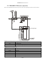
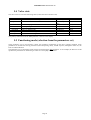
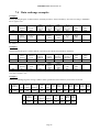
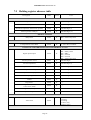
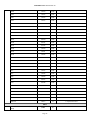
DRIVER
FOR ELECTRONIC EXPANSION
VALVES
TM168DEVCM
USER MANUAL
TM168DEVCM USER MANUAL
Summary
1
GENERALITIES .......................................................................................................................3
2
TECHNICAL FEATURES .......................................................................................................4
2.1
2.2
2.3
2.4
2.5
2.6
3
CONNECTIONS .......................................................................................................................4
TM168DEVCM ELECTRIC CONNECTION ..............................................................................5
TM168DEVCM DIMENSIONS AND INSTALLATION ...............................................................6
GENERAL FEATURES .............................................................................................................9
TECHNICAL FEATURES ..........................................................................................................9
ELECTRIC FEATURES ...........................................................................................................10
USER INTERFACE ................................................................................................................11
3.1
3.2
3.3
3.4
3.5
3.6
3.7
3.8
DISPLAY AND KEYBOARD ....................................................................................................11
MAIN PAGE .........................................................................................................................13
TEMPORARY DISPLAY OF THE QUANTITIES ..........................................................................13
SETTING THE WORK SET-POINT ...........................................................................................13
SETTING THE CONFIGURATION PARAMETERS ......................................................................13
RESTORE THE DEFAULT VALUE OF THE CONFIGURATION PARAMETERS ...............................14
MAIN MENU ........................................................................................................................14
DISPLAY OF FIRMWARE IDENTIFICATION .............................................................................14
4
LIST OF PARAMETERS .......................................................................................................15
5
FUNCTIONING.......................................................................................................................19
5.1
5.2
5.3
5.4
5.5
6
DIAGNOSTICS........................................................................................................................22
6.1
6.2
6.3
7
PRELIMINARY CONSIDERATIONS .........................................................................................19
ENABLING MODE FOR VALVE REGULATION .........................................................................19
MANUAL FUNCTIONING MODE ............................................................................................19
VALVE STATE ......................................................................................................................21
FUNCTIONING MODE (SELECTION FROM THE PARAMETERS SET)..........................................21
PROBE ALARMS ...................................................................................................................22
ALARM RELAY ....................................................................................................................22
ALARMS TABLE ...................................................................................................................22
LIST OF THE MODBUS VARIABLES................................................................................23
7.1
7.2
7.3
7.4
7.5
INTRODUCTION ...................................................................................................................23
ADDRESSING CONVENTIONS ................................................................................................23
IMPLEMENTED MODBUS FUNCTION CODES .........................................................................23
DATA EXCHANGE EXAMPLES...............................................................................................24
HOLDING REGISTER ADRESSES TABLE .................................................................................25
Page 2
TM168DEVCM USER MANUAL
1
Generalities
TM168DEVCM is a stand-alone driver for electronic expansion valves.
The instrument has:
•
1 measurement input for pressure transducers 4-20 mA (evaporation probe)
•
1 measurement input for NTC probes (intake probe)
•
1 high voltage digital input (functioning consent)
•
2 low voltage digital inputs (functioning consent and state of the back-up battery charge)
•
1 power supply input coming from the back-up battery
•
1 digital output (relay), 5 A resistif. @ 250 VDC, for alarm output control
•
1 serial port with MODBUS communication protocol
•
The device can function only with the Alco Control valves belonging to the EXM, EXL, EX4, EX5, EX6, EX7, EX8
and EX9 ranges.
The device is in 4 modules DIN module. The user interface is made up from a custom display with 4 digits (with
function icons) and 4 keys (set, up, down and escape).
Among the many features, the following are also indicated:
•
front panel protection rating IP54
•
management of high over-heating and low over-heating alarms
•
MOP function (Maximum Operating Pressure)
•
LOP function (Lowest Operating Pressure).
Page 3
TM168DEVCM USER MANUAL
2
Technical features
2.1 Connections
Power supply:
TM168DEVCM is powered by an alternating current equal to 24 V. The maximum length of the power supply
connection cables is 1 m. The TM168DEVCM power supply is not isolated; therefore it must be galvanically isolated
from other devices.
Connection of the analogue inputs:
TM168DEVCM has two analogue inputs, one for NTC temperature probe and one for pressure transducer
4-20 mA. The pressure transducer can be powered via a 12 VDC unstabilised voltage, available on an instrument clamp.
The maximum length of the analogue input connection cables is 3 m.
Connection of the digital inputs:
TM168DEVCM has three digital inputs of which two low voltage (functioning consent and back-up battery charge
state) non optoisolated and one in high voltage (functioning consent). The maximum length of the digital input
connection cables is 3 m.
Connection of the digital outputs:
TM168DEVCM has one digital output with electro-mechanical relay. The maximum length of the output connection
cables is 10 m.
Connection of the electronic expansion valve:
The maximum length of the electronic expansion valve connection cables is 6 m.
Precautions
The indications regarding the maximum lengths of the connections imply that a series of precautions are respected.
To prevent immunity problems, it is good practice to comply with the following indications:
avoid places with antennas
do not wire probe inputs with relay outputs; generally, prevent mixing
low and high voltage signals
do no wind cables around power components
Page 4
TM168DEVCM USER MANUAL
2.2 TM168DEVCM electric connection
Below find the TM168DEVCM connection layout with relative table regarding the meaning of inputs and outputs.
Connector 1: functioning consent relay output and digital input (high voltage).
Code
Description
NO1
K1 relay normally open contact
CO1
K1 common relay
COHV
Functioning consent digital input (230 VDC ± 15%)
COHV
Functioning consent digital input (230 VDC ± 15%)
Connector 2: electronic expansion valve.
Code (Alco reference)
Description for EXM-246 / EXL-246 (1)valves
V1
Shield
V2 (2B)
White wire
V3 (2A)
Orange wire
V4 (1B)
Blue wire
V5 (1A)
Yellow wire
Code (Alco reference)
Description for EX4 / EX5 / EX6 / EX7 / EX8 / EX9 valves
V1
Shield
V2 (2B)
White wire
V3 (2A)
Black wire
Page 5
TM168DEVCM USER MANUAL
(1)
V4 (1B)
Blue wire
V5 (1A)
Brown wire
The red wire and the brown wire are not used.
Connector 4: instrument power supply, back-up battery power supply, measurement inputs, digital inputs.
Code
Description
1
Instrument power supply (24 VDC)
2
Common analogue and digital inputs
3
Common analogue and digital inputs
4
Common analogue and digital inputs
5
Not used
6
Not used
7
Analogue input 2 (NTC temperature probe)
8
Analogue input 1 (pressure transducer 4-20 mA)
9
Instrument power supply (24 VDC)
10
Back-up battery power supply (12 VDC)
11
Pressure transducer power supply (12 VDC)
12
Not used
13
Not used
14
Not used
15
Functioning consent digital input
16
Back-up battery charge state digital input
Connector 5: to the TTL / RS-485 interface.
2.3 TM168DEVCM dimensions and installation
The mechanical dimensions of TM168DEVCM are given below; the measurements are expressed in mm (in).
Installation recommendations:
make sure that the work conditions (temperature of use, humidity, etc.) lie within the limits indicated in the
technical data
Page 6
TM168DEVCM USER MANUAL
-
-
do not install the instrument in proximity of heat sources (resistances, hot air pipes etc.) appliances with strong
magnets (large diffusers etc.), places subject to direct sunlight, rain, humidity, excessive dust, mechanical
vibrations or shocks
in compliance with Safety Standards, the protection against any contact with the electric parts must be ensured
via correct installation of the instrument. All parts that ensure protection must be fixed in a way such that they
cannot be removed without the aid of a tool
Page 7
TM168DEVCM USER MANUAL
To install TM168DEVCM, operate as indicated in the diagrams (points 1 and 2).
To remove TM168DEVCM, use a screwdriver and operate as indicated in the diagrams (points 3 and 4).
Page 8
TM168DEVCM USER MANUAL
2.4 General features
Reference Standards regarding safety
Purpose of the device
Storage conditions
Functioning conditions
Class according to the protection against electric shocks
Type of disconnection
PTI of the insulating materials
Container
Type of actions
Pollution
Class of software
Period of the electric stress of the insulating parts
Front panel protection rating
EN60730-1
Electronic expansion valve driver
-10T65 °C non-condensing R.H.<80%
0T50 °C non-condensing R.H.<80%
Control device to be integrated; assumes the classification
of the appliance with which it is integrated
Reduced interruption (relay contacts)
>=250V
Assembly on omega guide
1C
Normal
A
Long
IP40
2.5 Technical features
Connection for low voltage signals
Power connector
IntraBus serial port connection
Connection for the parameters key, TTL serial output for
RS-485 module, interface for Flash programming
Mini-Fit 16-way
Phoenix disconnectable terminal board
Cable section > 0.75mm2
Phoenix disconnectable terminal board
6-way AMP micro-maTch
SPECIFICATIONS OF THE 16-WAY MINI-FIT CONNECTOR
SUPPLIER
CONNECTOR CODE
CONTACTS CODE
Note:
use the appropriate tool for crimping
CVILUX
SELECOM
CP-01 116010 (V2)
CP-01 116020 (V0)
6137R16WO (V2)
JUSCOM
1090-557-162 (V2)
CONEXCON
6740-1161 (V2)
6740-1160 (V0)
39-01-2160 (V2)
39-01-2165 (V0)
MOLEX
Page 9
CP-01 1000102 (AWG16÷24)
6137TR1 (AWG16÷20)
6137TR2 (AWG22÷26)
1150-156-012 (AWG18÷22)
1150-156-002 (AWG22÷26)
6744-2000 (AWG18÷22)
39-00-0038 (AWG18÷24)
39-00-0046 (AWG22÷28)
TM168DEVCM USER MANUAL
2.6 Electric features
Power supply
Digital outputs
Valve motor outputs
Digital inputs in
low voltage
Digital inputs in
high voltage
Analogue inputs for
NTC probes
Analogue inputs for
pressure transducers
Back-up battery power supply input
back-up
Voltage
Range
Frequency
Maximum power absorbed
Protection fuse
Number
Type
Maximum contact current at 250Vdc
Number of manoeuvre cycles
Minimum interval between switch-overs
Type of micro switch interruption action
Insulation between the relay and low
voltage
Number
Type
Power supply
Number
Type
Current on the closing contact towards
earth
Maximum closure resistance
Detection time from OFF to ON
Detection time from ON to OFF
Number
Type
Voltage range
Min. detection time from OFF to ON
Min. detection time from ON to OFF
Number
Type
NTC measurement range
Number
Type
Current measurement range
Power supply
Input resistance
Voltage
Type of battery
Battery charger
Maximum power absorbed
Protection fuse
24 VDC
-10% +15%
50/60Hz
30VA
External
1
Electro-mechanical relays
3 (1) A
100.000
20s
1C
Reinforced
1
Step-by-step motor driver
Generated inside the module
2
Potential-free contact
2mA
100Ω
100ms
100ms
1
Optoisolated
230 VDC ± 20 %
100ms
100ms
1
NTC (10 KOhm ± 1 % @ 25 °C)
-50°C ÷ 50°C in fluid
-50°C ÷ 105°C in air
1
Current
4-20 mA
8 ... 30 VDC
< 200 Ohm
12 VDC
lead, 12 V, 2 ...6 Ah
I max = 150 mA, V max = 13 V
30VA
External
The high voltage digital output and the digital input have reinforced insulation with respect to the remaining I/O.
Page 10
TM168DEVCM USER MANUAL
3
User interface
3.1 Display and keyboard
The built-in interface on the controller is made up from a 4 digit custom display (for displaying quantities), 4 keys (for
surfing) and 16 icons (for immediate and intuitive representation).
Main functions that can be activated using the keys:
Key pressed
DOWN
during lamp test from power-on
DOWN
for 2 seconds
SET/ENTER
for 2 seconds
DOWN + UP
for 4 seconds
UP
Function
Display version/firmware revision
Quantity temporary display
Display/ over-heating set-point modification
(PH30=0 disables the possibility for modification)
Display/modify/reset parameters
Alarms display
Page 11
TM168DEVCM USER MANUAL
for 2 seconds
ESC
for 2 seconds
SET/ENTER + DOWN
for 2 seconds
Display /modify % valve output n manual mode
Block/Release keyboard
Meaning of the icons:
Icon
bar
Colour
Green
psi
Green
Green
valve closed
%
Amber
°F
Red
°C
Red
Red
maintenance
Red
alarm
HP
(MOP)
Green
LP
(LOP)
Green
SH
Green
SP
Green
Function
Identifies the unit of measurement selected. If on, it indicates
that the pressure is expressed in bar
Identifies the unit of measurement selected. If on, it indicates
that the pressure is expressed in psi
Identifies the valve state (closing):
Off: the valve is closed or off or <5%
On: the valve is open at a value > 95 %
Flashing: the valve is working
If on, it indicates that the % opening of the valve is being
displayed
Identifies the unit of measurement selected. If on, it indicates
that the temperature is expressed in °F-°R
Identifies the unit of measurement selected. If on, it indicates
that the temperature is expressed in °C-°K
Identifies the request for maintenance. If on, the valve is
operating in manual mode.
Identifies the presence or not of alarms. Alarms are present if
it is on, otherwise it remains off.
It is active when the MOP function is activated
Off: function not active
On: MOP function enabled
Flashing: MOP alarm
It is active when the LOP function is activated
Off: function not active
On: Low pressure alarm
Flashing: LOP alarm
It is active when the SH function is activated
Off: function not active
On: function on (I am viewing the SH value)
Flashing: LSH, HSH alarm
Identifies that a set-point is being displayed.
Flashing: the set-point is being modified.
Page 12
TM168DEVCM USER MANUAL
Green
Battery state (DI2)
Off: Battery charged
On: Back-up battery being charged or back-up module
disconnected
Identifies the state of the valve
Off: valve on (enabled)
On: valve off (disabled)
Flashing: valve in start-up
Identifies the Intrabus communication state
Off: No communication
On: Communication error
Flashing: Communication OK
Back-up battery
Red
on/stand-by
central decimal point
higher
Red
3.2 Main page
The main screen changes according to the state of the valve: if the valve is not enabled (vale open and regulation
deactivated) OFF is shown and the relative icon (stand-by) is on; if the valve is enabled (valve closed and regulation
activated) the values selected by the PdIS parameter is selected (or an error label). The relative icon (stand-by) is off (an
icon corresponds to the quantity displayed).
3.3 Temporary display of the quantities
Operate as indicated:
press the DOWN key for 2 seconds: the SH label is displayed
press the SET/ENTER key to display the over-heating value measured
press the UP or DOWN key to change the default display according to the following table:
SH
PrES
PErC
TEMP
TSAT
SHSP
SEtP
Over-heating value measured
Pressure value measured
% valve opening
Temperature value measured
Temperature value calculated (from the pressure)
Over-heating set-point value
Set of parameters currently selected
To exit the procedure:
press SET or do not operate for 60 seconds or press UP or DOWN until the display shows the quantity
established by the PdIS parameter or press the ESC key.
3.4 Setting the work set-point
Operate as indicated:
make sure that the machine is on, that the keyboard is not blocked and that no procedure is in progress
press the SET/ENTER key for 1 s: the display will show the current over-heating set-point
press the UP or DOWN key within 15 s
press SET/ENTER or do not operate for 15 s.
Using parameter PH30 it will be possible to block the possibility of modifying the set point; in his case, if you try to modify
the set-point, LOC is shown for 2 s.
3.5 Setting the configuration parameters
This paragraph presents the menus found in the application. The main menu is divided into two levels (user and
installer).
The installer level is protected by a password.
The range of values for those that can be set for the password is -99 / 999 (default = –19).
After 1 minute that no key is pressed, the password expires and must be set again.
To access the procedure, operate as indicated:
make sure no procedure is in progress
Page 13
TM168DEVCM USER MANUAL
press the UP and DOWN key for 4 s the display will show a label.
To select a parameter:
press the UP or DOWN key.
To modify a parameter:
press the SET/ENTER key
press the UP or DOWN key within 15 s
press the SET/ENTER key or do not operate for 15 s.
To access the installer level:
press the UP or DOWN key to select PA.
press the SET/ENTER key
press the UP key or the DOWN key within 15 s to set the password defined with the “PASS” parameter
(default -19)
press the SET/ENTER key or do not operate for 15 s
press the UP and DOWN key for 4 s the display will show a label.
To exit the procedure:
press the UP and DOWN key for 4 s or do not operate for 60 s.
Cut off the power supply to the instrument after modification of the parameters.
3.6 Restore the default value of the configuration parameters
Operate as indicated:
make sure no procedure is in progress
press the UP and DOWN key for 4 s the display will show a label
press the UP or DOWN key to select PA
press the SET/ENTER key
press the UP or DOWN key within 15 s to set 743
press the SET/ENTER key or do not operate for 15 s
press the UP and DOWN key for 4 s the display will show dEF.
press the SET/ENTER key
press the UP or DOWN key within 15 s to set 149
press the SET/ENTER key or do not operate for 15 s: the display will show flashing dEF for 4 seconds, after
which the instrument will exit the procedure
cut the instrument power supply off.
Make sure that the default value of the parameters is appropriate.
3.7 Main menu
It is possible to enter/display this menu holding the UP+DOWN keys down for 4 seconds.
The first variable displayed is rI00 (evaporation pressure); pressing SET/ENTER, the value is displayed. Using the UP
or DOWN keys, scroll the list of VCM variables in reading only mode.
To exit the procedure: press UP+DOWN for 4 seconds or do not operate for 60 seconds or press the ESC key.
3.8 Display of firmware identification
On switch-on, during the lamp test phase, holding the DOWN key, the project identification is displayed for about 2
seconds. The information regarding the versions/revisions of the project is displayed in sequence. The procedure is
exited automatically at the end of the lamp test.
Page 14
TM168DEVCM USER MANUAL
4 List of parameters
Below find the list of all parameters managed by the application. A brief description, the range of acceptable values,
unit of measurement, the default value and the menu in which it is found is supplied for every parameter. The menus are
structured according to the following logic: user menu (UT) allows to modify the overheating set-point. Installer menu
(IS) allows to modify all parameters; only if the installer menu is protected by a password.
Code
Parameter description
FUNCTIONING MODE
SEtP
Functioning mode
Default
Min
Max
U.M.
Menu
1
1
3
-
IS
6
0.5 (1.0)
2
0.5 (1.0)
30
0.5 (1.0)
-40.0
(-40.0)
-40.0
(-40.0)
30.0
(50.0)
30.0
(50.0)
50.0
(90.0)
40.0
(100.0)
40.0
(100.0)
K
(°R)
K
(°R)
K
(°R)
°C
(°F)
°C
(°F)
5
1
30
s
IS
50
10
100
%
IS
-40.0
(-40.0)
-40.0
(-40.0)
30.0
(50.0)
30.0
(50.0)
50.0
(90.0)
40.0
(100.0)
40.0
(100.0)
K
(°R)
K
(°R)
K
(°R)
°C
(°F)
°C
(°F)
5
1
30
s
IS
50
10
100
%
IS
6
0.5 (1.0)
2
0.5 (1.0)
30
0.5 (1.0)
-40.0
(-40.0)
-40.0
(-40.0)
30.0
(50.0)
30.0
(50.0)
50.0
(90.0)
40.0
(100.0)
40.0
(100.0)
K
(°R)
K
(°R)
K
(°R)
°C
(°F)
°C
(°F)
5
1
30
s
IS
50
10
100
%
IS
Notes
1 = Parameters Set1
2 = Parameters Set2
3 = Parameters Set3
SET1 (chiller)
PC01
PC02
PC03
Set Point Superheat Chiller
Set Point Low Superheat
Chiller
SP Superheat Chiller High
alarm
PC04
LOP Chiller Temperature
-30
PC05
MOP Chiller Temperature
30
PC06
PC07
Valve opening duration
from start-up
Valve opening % from
start-up
SET2 (heat pump)
PP01
HP Set Point Superheat
6
0.5 (1.0)
PP02
Set Point Superheat HP
2
0.5 (1.0)
PP03
SP Superheat HP High
alarm
30
0.5 (1.0)
PP04
LOP HP temperature
-30
PP05
MOP HP temperature
30
PP06
PP07
Pd01
Pd02
Pd03
Valve opening duration
from start-up
Valve opening % from
start-up
SET3 (defrost)
Set Point Superheat Def
Set Point Low Superheat
Def
SP Superheat Def High
alarm
Pd04
LOP temperature Def
-30
Pd05
MOP temperature Def
30
Pd06
Pd07
Valve opening duration
from start-up
Valve opening % from
start-up
PROTECTIONS
UT
SP Over-heating SET1
IS
IS
IS
IS
UT
SP Over-heating SET2
IS
IS
IS
IS
UT
SP Over-heating SET3
IS
IS
IS
IS
Note: Parameters common
Page 15
TM168DEVCM USER MANUAL
ALARMS
PA01
PA02
PA10
PA11
PA12
PA20
PA21
PA22
PA30
PA31
PA32
PA33
PA40
Enable communication
alarm
Communication alarm
delay T.
Enable Low Superheat
Alarm
Low Superheat alarm
hysteresis
Low Superheat alarm delay
T.
Enable High Superheat
Alarm
High Superheat alarm
hysteresis
High Superheat alarm
delay T.
Enable Low Pressure
Alarm
SP Low Pressure alarm
Low Pressure alarm
hysteresis
Low Pressure alarm delay
T.
Enable LOP Protection
Alarm
0
0
1
-
IS
30
5
200
s
IS
0
0
1
-
IS
3
0.5 (1.0)
30.0
(50.0)
K
(°R)
IS
3
0
250
min
IS
0
0
1
-
IS
3
0.5 (1.0)
30.0
(50.0)
K
(°R)
IS
3
0
250
min
IS
0
0
1
-
IS
-0.8
(-10.0)
0.1
(0.1)
50.0
(700.0)
1.0
(15.0)
Bar
(psi)
Bar
(psi)
3
0
250
min
IS
0
0
1
-
IS
15.0
(30.0)
250
°C
(°F)
min
IS
IS
0
0,3
PA41
LOP alarm hysteresis
3
PA42
LOP alarm delay T.
Enable MOP Protection
Alarm
3
0.1
(0.1)
0
0
0
1
-
0.1
(0.1)
0
15.0
(30.0)
250
°C
(°F)
min
PA50
PA51
MOP alarm hysteresis
3
PA52
MOP alarm delay T.
DISPLAY
3
PdIS
Value to show on the
display
to the various parameters
SET
0 =disabled
1 = standard enabled
0 =disabled
1 = enabled
0 =disabled
1 = enabled
0 =disabled
1 = enabled
IS
IS
0 =disabled
1 = enabled
IS
0 =disabled
1 = enabled
IS
IS
0
0
6
-
IS
0 = Over-heating value (K
or R)
1 = Evap. pressure
measured (bar/psi)
2 = % valve opening
3 = Intake temp. measured
(°C/°F)
4 = Saturate gas (°C/°F)
calculated (from P)
5 =SP overheating value
6 =SEtP selected
parameters
0
0
2
-
IS
0 = No
1 = Yes, manual
2 = Debug
0
0
100
%
IS
0
0
1
-
IS
0
0
100
%
IS
VALVE AND DRIVER
ENABLING
Pr02
Pr03
Pr04
Pr05
Enables manual
functioning of the valve
If in Manual func. mode,
set the valve output %
Enables valve forcing with
probe error
% valve in case of probe
error
Page 16
0 = No
1 = Yes
TM168DEVCM USER MANUAL
Pr06
Enabling mode for valve
regulation
Prd0
Prd1
Prd2
Step rate
% minimum opening
% maximum opening
BACKUP
Pb01
Back-up battery
0
0
3
-
IS
10
0
100
1
0
Prd1
200
Prd2
100
%
%
IS
IS
IS
0
0
1
-
IS
0 = From digital input DI1
1 = From digital input
DIHV
2 = From serial IntraBus
3 = ModBus
Step rate (ms) = Prd0 * 100
0 = absent
1 = present
VARIOUS
PH01
Enable alarm relay
0
0
2
-
IS
PH02
Relay logic alarm
0
0
1
-
IS
0
0
1
-
IS
1
0
1
-
IS
0
0
1
-
IS
0
0
1
-
IS
0
0
1
-
IS
1
0
1
-
IS
0
0
1
-
IS
PH10
PH11
PH12
PH20
PH21
PH22
PH30
PSPI
Mod5
Sets the D11 digital input
logic
Sets the D12 digital input
logic
Sets the D1HV digital
input logic
Sets the pressure unit of
measurement:
Sets the temperature unit of
measurement:
Sets the display of the
Schneider Electric icon
Disables set-point
modification from
keyboard using
SET/ENTER key
Sets clock frequency of the
SPI serial
SERIAL
NETWORK
(MODBUS)
Board Modbus Address
2
0
3
Khz
IS
1
1
247
n
IS
Mod6
Board communication
Baud Rate
2
0
3
n
IS
Mod7
ModBus Parity
2
0
2
n
IS
Mod8
StopBit ModBus
0
0
1
n
IS
0 = disabled
1 = enabled from any alarm
2 = enabled only for probes
error
0 = normally unexcited
1 = normally excited
0: Normally open NO
1: Normally closed NC
0: Normally open NO
1: Normally closed NC
0: Normally open NO
1: Normally closed NC
0: Bar
1: psi
0: °C
1: °F
Note K-R for over-heating
0: NO
1: YES
0: block function disabled
1: block function enabled
0 = 3.9 Khz
1 = 8.9 Khz
2 = 15.6 Khz
3 = 17.8 Khz
0 = 2400
1 = 4800
2 = 9600
3 =19200
0 = none
1 = Odd
2 = Even
0 = 1bit
1 = 2bit
PASSWORD
PASS
Installer level password
-19
-99
999
n
IS
The following parameters are those managed by the VCM module
After modification of the PI00, PI07 and/or PI08 parameter, the VCM module forces a reset.
Code
PI00
Parameter description
Type of refrigerant
Default
Min
Max
U.M.
1
0
7
-
Page 17
Notes
0 = R22
1 = R134A
2 = R507
TM168DEVCM USER MANUAL
PI03
Superheat control mode
0
0
2
-
PI07
Type of valve
2
1
7
-
3 = R404A
4 = R407C
5 = R410A
6 = R124
7 = R744
0 = Standard
1 = Slow
2 = Reserved
1 = EX4 Alco
2 = EX5 Alco
3 = EX6 Alco
4 = EX7 Alco
5 = EX8 Alco
6 = EX9 Alco
7 = EXM-246 or EXL-246
0 = EVPT530K00 (4-20 mA,
0 ... 7 bar relative)
1 = PT4-18S (4-20 mA Alco,
PI08
Type of pressure transducer
(evaporation probe)
0
0
3
-
0 ... 18 bar relative)
2 = EVPT530K01 (4-20 mA,
0 ... 30 bar relative)
3 = PT4-50S (4-20 mA Alco,
0 ... 50 bar relative)
PI09
PI10
PI11
Reserved
Reserved
Reserved
The following parameters are however available in reading mode only, at user level.
Code
Parameter description
Min
Max
U.M.
bar
(psi)
rI00
Evaporation pressure
rI01
Evaporation temperature
-50
50
°C
rI02
rI03
Intake temperature
Superheat Value
Valve opening percentage
value
-50
-50
50
50
°C
K
0
100
%
rI04
rI05
Pressure probe error
0
2
-
rI06
Temperature probe error
0
2
-
rI07
Step-by-step motor error
0
1
-
rI08
rI12
rI15
Unit alarms from VCM
Digital inputs state
VCM module revisions
0
0
7
2
-
Page 18
Notes
From evaporation probe
From evaporation pressure
(internal table)
From intake probe
0 = correct functioning
1 = sensor short circuit
2 = sensor open
0 = correct functioning
1 = sensor short circuit
2 = sensor open
0 = correct functioning
1 = in error mode
Alarm bit state
TM168DEVCM USER MANUAL
5
Functioning
5.1 Preliminary considerations
The points that qualify an electronically-piloted thermostatic valve with respect to a mechanical thermostatic valve are
the following:
compatibility with every type of refrigerant (or however with many types of refrigerant)
very large regulation range
microprocessor regulation and therefore total flexibility.
The first two points constitute a noteworthy advantage for the producer of machines or plants because they simplify the
logistics due to the consequent reduction of the codes and material to be managed and held in the warehouse. The
extended regulation range also allows to guarantee excellent over-heating stability also in conditions (condensation
pressure, evaporation pressure, over-heating value) distant from those of the project. mechanical thermostatic "works"
well around the project nominal conditions: shifting from these conditions, the over-heating value changes and in some
conditions becomes unstable. Because variability in the conditions of use is normal for cooling machines (consider an
air-cooled chiller), the thermostatic cannot guarantee the constant over-heating value and often, in order to keep overheating values acceptable also in day-to-day functioning it is forced to increase over-heating in greater functioning
conditions at the expense of plant efficiency.
The microprocessor regulation is a formidable potential that opens the doors of any innovation in the strategy of
regulation and use.
Some main features (and/or functionalities) of the electronic valves are: brief opening/closure times, high regulation
resolution, shut/off functionality, continuous flow modulation, "correct" stress in the cooling circuit.
5.2 Enabling mode for valve regulation
If the valve is closed (disabled and regulation deactivated), the display will show OFF and the on/stand-by icon is on.
The valve can be opened (enabled and regulation activated) in one of the two following ways (selectable from
parameter Pr06):
from digital input (stand-alone functioning enabled from parameter Pr06=0 or 1): in this case, it can be enabled
from optoisolated digital input (DIHV, Pr06=1) or from non-optoisolated digital input (DI1, Pr06=0). A typical
application is the use of an optoisolated digital input (230VAC) connected in parallel to compressor (therefore
the valve regulates when the compressor is on, otherwise it is off).
from IntraBus serial (function enabled by parameter Pr06=2): in this case, it can be enabled via the Intrabus
serial. A typical application is a chiller/heat pump that uses c-pro range controllers. This serial works with
settings relative to fixed communication and allows the use of two valves at a maximum
from ModBus serial (function enabled by parameter Pr06=3).
Whatever the enabling mode may be, there is a start-up procedure that keeps the valve open at a certain percentage
(from parameter Px07, where x = C, P or d) for a certain period of time that can be set (from parameter Px06); the
on/stand-by icon highlights the state. The display normally shows the quantity selected by the PdIS parameter + the
icon that indicates the unit of measurement of the quantity displayed.
5.3 Manual functioning mode
The program allows to set manual functioning for the valve. In this way, the over-heating algorithm is by-passed.
Manual functioning of the devices is useful when functional tests must be performed on the machine in order test the
integrity and correct functioning. Therefore, using the local keyboard, it is possible to enable the manual function and
set the valve output %; the same could be performed from the serial.
For reasons of safety and to prevent possible damage, the valve must be On (enabled) in order to operate in
manual mode.
The maintenance icon switches on during manual functioning. Forcing is performed via relevant parameters Pr02, Pr03.
In particular, with Pr02=0 the manual functioning is disabled. With Pr02=1 the manual functioning is enabled and Pr03
represents the % value that the valve output must assume. With Pr02=2 a particular manual command is enabled for
inspections where the valve output assumes a trend as represented in the figure; for every Prd0*100ms the valve output
% is increased or decreased between a value minimum Prd1 and a maximum value Prd2.
Page 19
TM168DEVCM USER MANUAL
% valve opening
100%
Prd2
Prd1
0%
Prd0 = Step rate
t
It is possible to operate in manual mode during normal valve functioning; this allows to test the behaviour of the chiller
where the valve has been inserted. Errors continue to be detected during this functioning. After a power cut, the valve
starts to function in manual mode.
During manual functioning, by pressing the ESC key for about 2 seconds, the % value that the valve output must
assume is displayed and set quickly.
Page 20
TM168DEVCM USER MANUAL
5.4 Valve state
The valve can be in one of the following states (visible also from relevant icons).
State
OFF
ON_START
ON
ON
ON
ON-MAN
OFF_ALL
ON_ALL
Description
Valve closed (mechanical stop)
Valve in start mode
Icon
On/stand by
On/stand-by
valve
valve position
valve position
valve position
maintenance
alarm
alarm
Valve is keeping the
Valve opening
Valve closing
Valve in manual mode
Valve closure following an alarm
Valve forced following an alarm
Display
OFF
+ (PdIS)
(PdIS)
(PdIS)
(PdIS)
(PdIS)
OFF (Blink)
(PdIS)
The quantity established with the PdIS parameter is shown on the display.
5.5 Functioning mode (selection from the parameters set)
Three parameters set are envisioned to satisfy the regulation requirements of the more complex machines. Each
parameters set includes the start-up parameters (time and opening value), the SH set-point, SH high/low alarm set, the
LOP set and the MOP set.
The parameters set (or functioning mode) will be selected using the SEtP parameter. As an example, the three sets could
represent the parameters for functioning as chiller or as heat pump or as defrost.
Page 21
TM168DEVCM USER MANUAL
6
Diagnostics
The application can manage a series of alarms relative to the valve. On the basis of the various types of alarms, it is
possible to configure any signalling delay.
The icon flashes when one or more alarms are active.
In order to display the various alarms, press the UP key from the main page for about 2 seconds; the first alarm present
is displayed; using the UP or DOWN keys, scroll all of the alarms present. If there are no alarms, pressing the UP key
for two seconds has no effect.
When the causes of the alarm have disappeared, the instrument will go back to normal functioning.
All of the digital inputs relative to the alarms (e.g.: battery charger input) are managed by an Alarms Logic parameter
that has the following meaning:
if set at NO, the inputs will be normally unexcited (open).
if set at NC, the inputs will be normally excited (closed).
6.1 Probe alarms
In the case of a probe alarm, the VCM module closes the valve. The two parametersPr04, Pr05can be used to enable
forcing of the valve (manual functioning) to a pre-defined value in order to allow temporary functioning.
6.2 Alarm relay
The program has the possibility of managing an alarm relay (parameter PH01). Via the relative parameter PH02 it is
possible to establish the polarity (NO or NC) of the alarm output. With PH01=0 the relay is disabled; with PH01=1 the
relay is enabled for all alarms envisioned (excluding the signalling only ones); with PH01=2 the relay is enabled only
for the probe errors detected by the VCM module.
6.3 Alarms table
Below is a list of all alarms managed by the application. The order of presentation is the same as the order with which
the alarms are presented when active.
Code
ESPI
Alarm description
Communication error with VCM controller
ECom
Communication error with main controller
EPr1
Pressure transducer faulty or disconnected
EPr2
Temperature probe faulty or disconnected
ALSm
ALHS
ALLS
Valve step-by-step motor error
High over-heating
Low over-heating
ALLP
Low pressure
LOP
MOP
LOP
MOP
Problems with the electric mains (displayed
only if back-up battery is present)
PFIr
Page 22
Consequence
The
valve
completely.
The
valve
completely
The
valve
completely
Notes
Fixed delay
closes
PA01, PA02
closes
closes
The SH LED flashes
The SH LED flashes
The LP LED switches
on
The LP LED flashes
PA20, PA21, PA22
PA10, PA11, PA12
PA30, PA31, PA32,
PA33
PA40, PA41, PA42
PA50, PA51, PA52
TM168DEVCM USER MANUAL
7
List of the ModBus variables
7.1 Introduction
This document describes the resources of the device that can be accessed via the serial port. The protocol is MODBUS
RTU.
7.2 Addressing conventions
Please note that according to MODBUS specs:
the first register is called register 1
register x must be read ad address x-1
7.3 Implemented ModBus function codes
Command
Function Code
Notes
READ HOLDING REGISTERS
$03
Maximum 95 registers at once
WRITE SINGLE REGISTER
$06
WRITE MULTIPLE HR
$10
Page 23
Maximum 95 registers at once
TM168DEVCM USER MANUAL
7.4 Data exchange examples
Example 1:
Reading Holding Register at address $0601 (the SEtP parameter, function modality). Note that according to MODBUS
that is register 1538
TX
RX
High
Starting
Address
$06
Slave
Address
Function
Code
$F7
$03
Slave
Address
Function
Code
Byte Count
$F7
$03
$02
Low
Starting
Address
$01
High
Low
Quantity of Quantity of
Register
Register
$00
$01
High
Register
value
$00
Low
Register
value
$01
Low
CRC
High
CRC
$C1
$D4
Low
CRC
High
CRC
$B1
$91
the value is 1.
Example 2:
Reading Holding Register at address $FF08, representing the FW.ID field (FirmWare IDentifier).
TX
RX
High
Starting
Address
$FF
Slave
Address
Function
Code
$F7
$03
Slave
Address
Function
Code
Byte Count
$F7
$03
$02
Low
Starting
Address
$08
High
Low
Quantity of Quantity of
Register
Register
$00
$01
High
Register
value
$01
Low
Register
value
$8D
Low
CRC
High
CRC
$21
$4A
Low
CRC
High
CRC
$B1
$A4
The value is $018D = 397
Example 3:
Writing two Holding Registers starting at address $0607 (parameters PC06 and PC07) with values 10 and 100.
T
x
Slave
Address
Func
tion
Code
High
Starting
Address
Low
Starting
Address
High
Num
HR
Low
Num
HR
Byte
cnt
Data1
High
Data1
Low
Data2
High
Data2
Low
CRC
High
CRC
High
$F7
$10
$06
$07
$00
$02
$04
$00
$0A
$00
$64
$A5
$8B
Slave
Address
Func
tion
Code
High
Starting
Address
Low
Starting
Address
High
Num
HR
Low
Num
HR
CRC
High
CRC
High
$F7
$10
$06
$07
$00
$02
$E4
$17
R
x
Page 24
TM168DEVCM USER MANUAL
7.5 Holding register adresses table
Description
Index
Access
Notes
PROBES
Suction pressure in mA
$0201
R
2 decimal digits
Coil out temperature
$0202
R
1 decimal digit (*)
Saturation temperature from suction pressure
$0203
R
1 decimal digit (*)
Suction pressure in Bar/psi
$0204
R
1 decimal digit (**)
R
Bit0 = Alarm relay status
W
1= store data in EV-KEY
DIGITAL OUTPUTS
Relay status
$0181
APPLICATION COMMANDS
Load parameters in EV-KEY
$0470
CONTIGUOUS INFORMATIONS ABOUT INSTRUMENT STATUS
Digital inputs/output
$0550
R
Bit0 = di1
Bit1 = battery status
Bit2 = diHV
Bit3 = reserved
Bit4 = reserved
Bit8 = Alarm relay status
Suction pressure in mA
$0551
R
2 decimal digits
Coil out temperature
$0552
R
1 decimal digit (*)
Saturation temperature from suction pressure
$0553
R
1 decimal digit (*)
Suction pressure in Bar/psi
$0554
R
1 decimal digit (**)
Superheat value [K]
$0555
R
1 decimal digit
Valve opening in %
$0556
R
1 decimal digit
Alarms
$0557
R
( 1)
Flag status 1
$0558
R
( 2)
Flag status 2 (MSB)
Valve status (LSB)
$0559
R
( 3)
Mode configuration (SEtP parameter)
$055A
R
Superheat set point
$055B
R
VALVE STATUS
Valve status
$0502
Page 25
0: off
1: starting
2: running
3: close (<5%)
4: open (>95%)
TM168DEVCM USER MANUAL
(*)
(**)
LOP temperature set point
$0510
MOP temperature set point
$0511
Set point super heat
$0512
Length of valve initialization
$0513
Percent opening during valve initialization
$0514
Set point low superheat alarm
$0515
Set point high superheat alarm
$0516
the measure unit depend on parameter PH21 (0:°C, 1:°F)
the measure unit depend on parameter PH20 (0:Bar, 1:psi)
Description
Index
Access
Notes
81 parameters
PARAMETERS
Number of parameters
$0600
R
SEtP
$0601
R/W
PC01
$0602
R/W
PC02
$0603
R/W
PC03
$0604
R/W
PC04
$0605
R/W
PC05
$0606
R/W
PC06
$0607
R/W
PC07
$0608
R/W
PP01
$0609
R/W
PP02
$060A
R/W
PP03
$060B
R/W
PP04
$060C
R/W
PP05
$060D
R/W
PP06
$060E
R/W
PP07
$060F
R/W
Pd01
$0610
R/W
Pd02
$0611
R/W
Pd03
$0612
R/W
Pd04
$0613
R/W
Page 26
TM168DEVCM USER MANUAL
Pd05
$0614
R/W
Pd06
$0615
R/W
Pd07
$0616
R/W
PA01
$0617
R/W
PA02
$0618
R/W
PA10
$0619
R/W
PA11
$061A
R/W
PA12
$061B
R/W
PA20
$061C
R/W
PA21
$061D
R/W
PA22
$061E
R/W
PA30
$061F
R/W
PA31
$0620
R/W
PA32
$0621
R/W
PA33
$0622
R/W
PA40
$0623
R/W
PA41
$0624
R/W
PA42
$0625
R/W
PA50
$0626
R/W
PA51
$0627
R/W
PA52
$0628
R/W
PdIS
$0629
R/W
Pr02
$062A
R/W
Pr03
$062B
R/W
Pr04
$062C
R/W
Pr05
$062D
R/W
Pr06
$062E
R/W
Prd0
$062F
R/W
Prd1
$0630
R/W
Prd2
$0631
R/W
Pb01
$0632
R/W
PH01
$0633
R/W
Page 27
TM168DEVCM USER MANUAL
PH02
$0634
R/W
PH10
$0635
R/W
PH11
$0636
R/W
PH12
$0637
R/W
PH20
$0638
R/W
PH21
$0639
R/W
PH22
$063A
R/W
PH30
$063B
R/W
PSPI
$063C
R/W
Mod1
$063D
R/W
Mod2
$063E
R/W
Mod3
$063F
R/W
Mod4
$0640
R/W
Mod5
$0641
R/W
Mod6
$0642
R/W
Mod7
$0643
R/W
Mod8
$0644
R/W
PASS
$0645
R/W
PI00
$0646
R/W
PI03
$0647
R/W
PI07
$0648
R/W
PI08
$0649
R/W
PI09
$064A
R/W
PI10
$064B
R/W
PI11
$064C
R/W
PI12
$064D
R/W
PI13
$064E
R/W
PI14
$064F
R/W
PI15
$0650
R/W
Kbd lock
$e053
R
INFO
Driver Identifier A: same as $FF08
(397)
$ff02
Page 28
R
1= keyboard locked
TM168DEVCM USER MANUAL
Driver Identifier B: same as $FF09
$ff03
R
Firmware ID
$ff08
R
Firmware Variation/revision
$ff09
R
1
( ) Alarms: at address $0557 :
Alarms
Mask value
Low superheat
$0001
High superheat
$0002
LOP
$0004
MOP
$0008
SPI comunication
error
$0010
Battery status
$0020
Low pressure
$0040
Electrical net status
$0080
Pressure probe
failure
Temperature probe
failure
Motor failure
1: battery embty or
charging
1: electrical net is
active
$0100
$0200
$0400
2
( ) Regulator flags (2): at address $0558:
Flag
Manual function
activated
Enabling input
status
Input HV
Manual function
activated during
probe failure
Remote valve
enabling
Mask value
$0001
$0002
$0008
$0010
$0020
On/Off status
$0040
VCM module
compatibility
$0100
2
( ) Regulator flags (3): at address $0559:
Flag
Mask value
Power failure
occurred
$0001
Page 29
0: Off
1: On
TM168DEVCM USER MANUAL
Instrument
configuration varied
$0002
No new info to read
$0010
New info to read
$0020
PAY ATTENTION:
ALL THE ADDRESSES NOT MENTIONED EXPRESSLY IN THIS DOCUMENT MUST BE CONSIDERED
RESERVED. ALL THE ADDRESSES INDICATED AS RESERVED MUST NOT BE READ OR WRITTEN;
IF YOU DO NOT RESPECT THIS CONDITION, YOU COULD ALTER THE OPERATION OF THE
INSTRUMENT.
Page 30