1
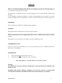
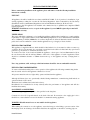
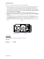
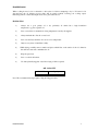
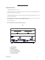
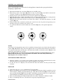
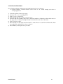
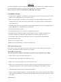
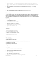
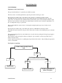
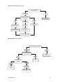
INSTALLATION AND USER INSTRUCTIONS
FOR DF7 GAS FRYER
IS356 ECN3258
INDEX
•
FOREWORD
3
•
INSTALLATION INSTRUCTIONS
4-5
Ventilation.
Installation position.
Installation commissioning.
Gas supply and connection.
Pressure setting.
Heat input.
•
NOTES ON FRYING
6-7
Frying media.
Frying times.
Frying tips.
Oil capacity
•
OPERATING INSTRUCTIONS
8-10
Initial start-up.
Operating instructions.
Drainage and cleaning.
•
SERVICING
11-13
General routine servicing.
Component replacement.
Spares list.
•
TROUBLESHOOTING
14-15
•
SPARES LIST
16
•
TECHNICAL SPECIFICATION
16
•
SERVICE
17
Contact information.
Lincat service department.
Conditions of guarantee.
IS356 ECN3258
2
FOREWORD
Thank you for buying this Lincat product, which we hope will give you years of trouble free service. To
ensure you receive the maximum benefit from your new fryer please take the time to read this instruction
book carefully, following any directions given.
We manufacture over 300 different items of catering equipment and are constantly adding to and improving
the range.
If you’re thinking of extending your kitchen or renewing a catering appliance in the near future, see our sales
brochures available from your local distributor or send for one direct from us before you make your decision.
IMPORTANT
Please read this page carefully before initially using the equipment.
WARNING
This appliance must be installed and serviced by a registered engineer.
Whilst in operation, parts of the catering equipment will become hot. Suitable precautions must be taken to
avoid accidental burns, therefore the appliance should be positioned to minimise the possibility of accidental
touching.
This appliance is for professional use and shall be operated by qualified personnel.
CONSEQUENTIAL LOSS
Lincat do not accept any responsibility for loss of food, production time, profit, etc., which may result from a
break-down of the equipment
MAINTENANCE
1)
2)
These units must not be cleaned using a water jet.
Clean units with water and detergent - do not use abrasives.
Parts of this appliance – especially the flue, become hot in operation.
Warning
Parts which have been protected by the manufacturer or his agent must not be adjusted by the
installer or user
Installation must include sufficient ventilation to prevent the occurrence of unacceptable
concentrations of substances harmful to health in the room in which they are installed
IS356 ECN3258
3
INSTALLATION INSTRUCTIONS.
Before commencing installation of the appliance please take time to read the following installation
instructions carefully.
UNIT: DF7
All appliances should be installed in accordance with BS 6173:2001, Code of practice for installation of gas
catering appliances, taking into account the Gas Safety Regulations 1984 as amended by the Gas Safety
(Installation and Use)(Amendment) Regulations 1998 and the Health and Safety at Work Act 1974.
It is mandatory that all appliances are installed and commissioned by a qualified and competent CORGI
registered gas fitter.
WARNING: Installation, service or repair of this appliance by non-CORGI registered personnel will
invalidate its warranty.
VENTILATION
The area in which this equipment is to be installed should have sufficient fixed ventilation to comply with the
requirements of Approved Document J in the 2002 Building Regulations. It is recommended that a minimum
Area of 450mm2 per 1kWh (3400Btu/hr) of total heat input must be allowed. Particular attention should be
paid to the low level ventilation to ensure that the appliance has a good supply of clean, fresh air.
INSTALLATION POSITION
This appliance is supplied with feet, which should be fitted when it is to be mounted on either a counter top
or tabletop. If it is to be mounted on to a pedestal or stand, the feet should not be fitted and only open fronted
pedestals, e.g. model CN7 or stand SLS7 should be used.
To ensure a free flow of air around and behind the appliance, a clear space of at least 20mm must be left at
the rear between flue and the wall and 50mm to either side of the appliance or bank of appliances. There
should be a minimum clearance of 750mm between the top of the appliance and any overlying shelf or
ceiling.
Note: Any partitions, walls, worktops or kitchen furniture should be of non-combustible materials.
INSTALLATION COMMISSIONING.
To ensure a full understanding of the correct operation of the appliance the following commissioning checks
must be carried out before the appliance is handed over for use.
All operators must know how to light, safely operate and shutdown the appliance.
Although all Lincat fryers are operationally checked during manufacture, commissioning shall include an
operational check of all controls.
The thermostat is calibrated and sealed at the factory.
Re-calibration is not authorised as it may adversely affect the performance of the appliance and will also
invalidate the warranty.
GAS SUPPLY & CONNECTION
Check that the gas supply corresponds to that specified on the data plate.
Connection is via a 1/2" bspt male thread on the back of the unit. If connection to the supply pipe is via a
flexible hose, ensure that the hose used is suitable for commercial catering appliances.
WARNING: Black domestic hoses are not suitable for this appliance.
When making the connection on to the appliance, secure the hexagon on the fitting to prevent rotation of the
internal pipe work. An isolating cock should be fitted into the supply line to the unit for servicing purposes.
IS356 ECN3258
4
PRESSURE SETTING
There are two burners in the DF7 - each burner needs setting individually.
1. To access the pressure test points, take off control panel as follows. Drain tank and point drain tap levers
directly forward. Remove control knobs. Unscrew screws beneath control panel front flange. Lift
control panel away at the bottom and disengage tabs at the top. Disconnect igniter leads if necessary.
2. Use the test point provided on the gas control valves marked “IN” (Fig 1, A), to check the supply inlet
pressure. (Refer to technical data table on page 16). Note: An external regulator should be fitted to the
fryer if the inlet pressure exceeds 50mbar
3. Use the test point marked “OUT” (Fig 1, B), to set the unit to the appropriate burner pressure.
4. Adjustment is made via the valve’s onboard governor, which is situated centrally on the valve. (Fig 1, C).
5. Remove the governor cap and turn the screw clockwise to increase the outlet pressure and anticlockwise
to reduce it.
6. With one main burner lit, (refer to operating instructions, page 8), adjust the burner pressure at the
corresponding valve by the method described above to the appropriate value of 25mbar for Propane gas
and 15mbar for Natural gas. Repeat procedure for the other burner using the other valve.
7. After setting, ensure each governor cap is properly secured and the blanking screws replaced in the test
points.
Fig 1.
A
B
C
HEAT INPUT.
The total nominal gross heat input for the appliances are as follows: Models DF7
Propane gas.............
Natural gas............
IS356 ECN3258
17.0 kWh
17.0 kWh
5
NOTES ON FRYING MEDIA
Ensure oil is always maintained at the level indicated (H-high, L-low). Good quality vegetable oil is
recommended. Animal fat may be used - but must always be melted first. Animal fat has a lower smoke and
fire temperature than vegetable oil and taste is transferred when cooking with it (e.g. onions fried in animal
fat will taint other foods i.e. fish which may follow). This does not occur when cooking with vegetable oil.
The life expectancy of oils and cooking fats will be lengthened if they are filtered regularly - food particles
not removed turn rancid and reduce oil/fat quality.
Vegetable oils and animal fat are incompatible - e.g. if sausages containing a lot of animal fat are fried in
vegetable oil, the oil will tend to "glue" and spoil.
The life of oil or fat will also be extended if the temperature is turned down when the fryer is not in use otherwise if left "full-on" the oil is being subjected to needless heat treatment and thereby destroyed.
Used oil symptoms firstly indicate discolouration by darkening. The oil becomes thin its fat content having
become exhausted. The next symptom is an unhealthy yellow foam which may appear on the surface, and the
third and more serious one is that the oil will boil or "surge" if not changed - thereby causing damage. Be
safe, not sorry. Keep your oil in good condition and ensure a healthier food product and happier customers.
Please note also, that "spent" oil will have a lower flash point than new oil and therefore present a greater fire
hazard. Also avoid overflow from over-wet loads or over-large batches.
In time, oil/fat may build up as a dried-on residue on tanks, baskets etc., although this can be minimised on
baskets by regular washing in hot water and detergent. If, subsequently, it cannot be removed by normal
cleaning, various branded cleansers are available such as "Carb '
n'off" which makes removal easy after
overnight application. Carb ‘n’ off is available from us Part No. FCB01.
If a fryer is to be out of use for a lengthy period, drain and clean the tank. Lightly oil tanks below the batter
plate with cooking oil.
Warning: Always allow oil to cool to a maximum 55 oC before draining.
A GUIDE TO FRYING TIMES
Food Type
Fish
Chips - blanching
Chips - browning
Chicken
Fritters
Scampi
Mushrooms
IS356 ECN3258
Frying Time
3-4 mins
3-4 mins
2-3 mins
9-12 mins
4-5 mins
4-5 mins
2-3 mins
Temperature
170°C
160°C
190°C
160°C
180°C
180°C
180°C
6
FROZEN FOODS
When cooking frozen food, it is advisable to defrost the food before attempting to fry it. If frozen food is
deposited into the oil, heating recovery times will be greatly reduced, lowering your cooking output.
Defrosting will also ensure that surplus water is not placed into the oil.
FRYING TIPS
1)
Always use a good quality oil or fat, preferably oil which has a high breakdown
temperature e.g. pure vegetable oil.
2)
Do not exceed the recommended cooking temperature stated by the supplier.
3)
Always maintain the oil at the correct level.
4)
Do not use the Fryer until the oil is at its correct temperature.
5)
Only use very clean oil and filter it daily.
6)
Whilst frying, carefully remove crumbs and pieces which float on the surface of the oil, otherwise
this will carbonate and contaminate the oil.
6)
Keep the pan clean.
8)
Do not overload the baskets.
9)
Use batter plate/frying plate only if free frying of fish is required.
OIL CAPACITY
Model No.
DF7
Capacity
6 litres per Tank
Note: The recommended frying weight is 750g (0.75kg) per basket.
IS356 ECN3258
7
OPERATING INSTRUCTIONS
PREPARATION FOR USE
1. Ensure that the drain valve is closed.
2. Fill the tank with water and a little mild detergent. Turn the unit "ON" (see Operating Instructions)
and allow the water to boil for a short time.
3. Switch off and drain off the water. Rinse the tank and dry thoroughly. Ensure that the drain
and tap are dried thoroughly.
pipe
4. Run a small quantity of oil across the base of the tank and allow to drain to waste. This will remove
any residual water and provide the base of the tank with a coating of oil.
5. Close the drain valve.
Note: Lids must not be used when cooking is in progress.
Fig 2
1
1
6
7
3
6
3
7
4
5
1.
2.
3.
4.
5.
6.
7.
8.
IS356 ECN3258
8
2
5
8
2
4
Thermostat Knob
Gas Control Valve
Igniter Button
Pilot Viewing Window
Drain Valve Blanking Cap
Drain Valve Operating Handle
Drain Valve Safety Latch
Limit Stat Reset Button
8
LIGHTING of the APPLIANCE.
Please ensure that the gas isolation valve for the appliance is turned to the open position before
attempting to light this unit.
1. Ensure that the thermostat control knob (Fig 2, 1) is in the OFF position.
2. Ensure the gas valve control knob (Fig 2, 2) is in the off position (Fig 3, A). Push in and turn anti3.
4.
5.
6.
7.
clockwise to the Pilot position (Fig 3, B). The knob will now depress further.
Keeping the pilot control knob depressed, press the piezo ignition button (Fig 2, 3).
Ensure the pilot flame is alight, a blue flame can be seen when looking into the pilot viewing window
(Fig 2, 4). Hold the pilot control knob in for 20 seconds to establish the pilot flame.
When the pilot is lit, release the pilot control knob and continue to turn fully anti-clockwise to the ON
position (Fig 3, C).
If the pilot flame fails to remain lit, return the pilot control knob to the off position and repeat the process
allowing a short period of time for the control to reset.
To operate the main burner, turn the thermostat control knob (Fig 2, 1) to the required temperature
setting.
Fig 3
ON
OFF
B
OFF
ON
PILOT
OFF
ON
A
PILOT
PILOT
C
Standby
Once the pilot is lit the appliance may be left on standby by leaving the pilot control knob in the pilot ignition
position. (Fig 3, B). When in this position the appliance cannot be operated from the thermostat control knob.
To re ignite the main burners turn the pilot control knob anti-clockwise to the burner position, (Fig 3, C), and
operate the control thermostat as normal.
Note: Should the safety cut-out thermostat operate during normal use the unit will shut down. To relight the unit allow the oil to cool to a temperature below 200oC. Re-set the safety thermostat by
depressing the red re-set button. (Fig 2, 8).
SHUT DOWN OF THE APPLIANCE
1) When the appliance is not required, turn the thermostat fully anti-clockwise which will shut down the
main burner but leave the pilot lit ready for when the appliance is next required.
2) To turn the unit off completely, turn the thermostat fully anti-clockwise and the pilot knob fully
clockwise.
DRAINAGE
1) Always allow the oil to cool to a maximum 55 oC before draining.
2) Remove the blanking nuts from the front of the unit (Fig 2, 5). Fit the pipe which is normally stowed in
the lid and place a suitable receptacle under the pipe outlet. Lift the safety catch (Fig 2, 7) and operate the
tap by moving the handle (Fig 2, 6) to the right to drain. Remove the pipe and fit into its storage position
in the lid. Replace the blanking nut and close the tap before refilling the tank.
3) Take care when draining the oil that the drain bucket is not filled so full that it is difficult to handle.
4) Excess oil remaining in the base of the tank can be mopped up using kitchen paper.
IS356 ECN3258
9
CLEANING INSTRUCTIONS
Note: Clean the appliance with hot water and a mild detergent do not use abrasives.
In extreme conditions a branded cleanser such as “Carb ‘n’ off ” makes cleaning easier after an
overnight application.
1)
2)
3)
4)
5)
Isolate the appliance from the gas supply.
Allow the oil to cool to a maximum 55 oC.
Drain as per above instructions.
Wash the tanks and the top surface of the fryer body.
Clean the drain tube assembly, using a tube or flue brush suitable for 15mm tube, with the drain valves in
the open position. Clean by inserting the brush into both the inlet and outlet of the drains.
6) Wash all parts thoroughly.
7) Ensure all parts are thoroughly rinsed and dried. To ensure there is no water left in the drain tube, flush
thoroughly with a small amount of clean cooking oil.
8) Re-assemble by reversing the above procedure.
IS356 ECN3258
10
SERVICING
Gas catering equipment should be routinely serviced to ensure a long trouble-free life. With this in mind it is
recommended that the appliances are serviced every 6 months by a competent gas engineer.
Please see Page 17 “Service” for information on authorised service agents.
DF7 GENERAL SERVICE
1. General check of equipment, e.g. installation - is the unit on the correct hoses? does the hose have a safety
chain? does the equipment have a separate isolation valve?
2. Remove the facia panel by removing the screws beneath the front edge and lifting forward and down to
disengage the top tabs. Disconnect the piezo igniter leads. Access is then gained to the multi-function
valve, thermostats etc.
3. Check and adjust where necessary the burner pressure with the unit in full operation at the right hand test
nipple. (Fig 1, B). See “Technical Data” for information.
4. Check the general burner condition.
5. Check the thermostats for correct operation. Temperature test the unit.
6. Check that the pilot assembly is burning correctly, clean if necessary. (See Pilot Assembly below)
7. Check the spark electrode and thermocouple within the pilot assembly. Adjust if necessary.
8. Check thermocouple output between interrupter junctions. (Voltage should be 7mV minimum).
9. Ensure that the flue is clear.
10.Carryout a gas soundness check
11.Refit facia panel remembering to reconnect piezo igniter leads.
DF7 Component Replacement.
Note: Access to some of the components referred to in this section can only be gained by separating the
base/sides of the appliance from the tank and hob top assembly.
Base and Hob top Separation.
Note: The fryer must be emptied of oil and disconnected from the gas supply before proceeding.
1. Remove all loose parts, lid, baskets, batter plate etc.
2. Detach flue back by removing screws holding flue to body.
3. Remove the control knob and undo the control thermostat screws.
4. Remove the screws beneath the control panel to allow control panel to be lifted forward and down to
disengage the tabs. Remove the 2 screws beneath the base holding the front heatshield to the base.
5. Disconnect igniter leads and remove control panel completely.
6. Remove the nuts holding the drain tap to the drain tap bracket. Lift out safety lock arms. Undo the limit
stat nuts and free the limit stats. Disconnect limit stat wiring to interrupted t/couples. Disconnect control
stat wiring.
IS356 ECN3258
11
7. Unscrew flue at back. Body and hob are interlocked by 3 formed steel hook and slots each side – to
separate, push hob top back until hooks disengage, and then lift hob and tank assembly clear of base and
sides.
8. Take care, as the limit thermostat and safety stat will remain attached to hob top – do not damage
capillaries.
9. Carry out any work necessary and reassemble in the reverse order of 1-7 above.
Pilot Assembly.
To access the pilot assembly, firstly remove the control panel as per Step 4 above. Either pilot assembly can
then be lowered through the base of the unit by unscrewing the appropriate pilot box from beneath the unit,
and loosening the pilot pipe at the valve joint. Carefully remove the pilot box - all pilot components can then
be accessed.
Thermocouple.
1. Loosen retaining nut at valve.
2. Loosen retaining nut at pilot assembly.
3. Disconnect cabling from the interrupter.
4. Withdraw thermocouple from pilot assembly.
5. Replace as above in reverse order.
Thermopile
1. Disconnect thermopile lead at valve.
2. Loosen retaining nut at pilot assembly
3. Withdraw thermopile from pilot assembly.
4. Replace as above in reverse order.
Limit Thermostat.
1. Loosen tank gland.
2. Remove drain valve safety latch.
3. Loosen limit thermostat nut and withdraw from bracket. Disconnect wiring.
4. Withdraw probe from tank
5. Thermostat can now be removed.
6. Replace as above in reverse order.
Control Valve
1. Disconnect all wire connections on valve terminals.
2. Disconnect interrupted thermocouple from valve.
3. Undo pilot feed pipe.
4. Undo supply pipe and burner pipe unions.
5. Remove two screws from each side of valve support brackets.
IS356 ECN3258
12
6. Withdraw valve
7. Remove unions from valve for re-use.
8. Replace as above in reverse order.
9. For Propane gas units, remove the governor cap, unscrew the adjuster and remove with the spring.
10. Replace spring with Lincat part number SP65 and reassemble.
11. Reset burner pressure as per “Installation instructions”, “Pressure setting”.
Burner and jet.
1. Remove the aeration box top cover at the rear of the burner
2. Undo the pipe union on the burner elbow.
3. Remove the burner retaining nut at the front of the burner
4. Withdraw the burner assembly.
5. To gain access to the jet, remove the elbow.
6. Replace as above in reverse order.
IS356 ECN3258
13
TROUBLESHOOTING
FAULT FINDING
Explanation of the Control System
The gas circuit in this fryer is operated by two millivolt systems.
The first consists of an interrupted thermocouple, the pilot burner and the gas control.
Heat from the pilot flame acting on the thermocouple generates a 15-30 mV electrical potential.
This millivolt system connected to the gas control operates the first solenoid that allows gas to the pilot
burner. The over temperature stat is included in this system which operates via the interrupted thermocouple.
The first solenoid operates as the safety device which shuts down in the event of a thermocouple failure or if
the over temperature stat goes open circuit.
The secondary millivolt system consists of a thermopile acting through the gas control via the control
thermostat.
Heat from the pilot flame acting on the thermopile generates a 500-700 mV electrical potential.
This millivolt system connected to the gas control operates the secondary solenoid that passes gas to the main
burners.
The system is interrupted by the control thermostat as it cycles, thereby opening and closing the gas supply to
the main burners.
The following trouble shooting flow charts are designed to give assistance on the most probable cause of
failure of the gas circuit.
Use the step-by-step instructions to quickly pinpoint problems and the advice to help in taking the appropriate
action to rectify them.
Piezo Igniter not sparking.
Is there a short in the High Tension
Lead.
No
Has Electrode Insulator Fractured.
Yes.
Yes.
No.
Replace Electrode.
If no spark is generated at all,
replace Piezo Ignitor.
Replace Lead.
IS356 ECN3258
14
Pilot burner will not light or stay lit.
Are the thermocouple/Interrupter
connections secure.
Yes.
No
Is there gas at the pilot when
holding control knob in the
pilot position.
Yes.
Tighten connection.
No.
Very little.
Check overtemperature
stat for open circuit.
Check supply.
Check thermocouple
voltage (minium 15mV).
Check pilot jet for
blockage and clean where
necessary.
Check supply.
If all of the above are OK the
control valve may be faulty.
High limit thermostat operates.
Is the oil temperature over 220oC.
Yes.
No
Does the control stat
operate on temp. rise when
set point is low (100oC).
No.
Yes.
Are the connections
correct on the gas
control.
Yes.
Replace
overtemperature
stat.
Replace
overtemperature stat.
Replace control
stat.
No.
Correct
connections.
Manually reset overtemp
stat.
IS356 ECN3258
15
SPARES LIST.
The following components are listed with the Lincat reference number followed by a brief description.
IG15
IG06
IG12
PI08
VA20
TH96
TC39
TC20
TH99
Igniter Electrode.
Igniter Lead
Igniter
Pilot assembly.
Multi function valve.
Safety limit stat.
Interrupted Thermocouple.
Thermopile
Control Thermostat
TECHNICAL SPECIFICATION
(Model DF7).
Dimensions
Weight
Inlet connection
IS356 ECN3258
H W
D
425 x 750 x 600
46kg
1/2 BSP
Heat Input (Gross).
Supply Pressure
Burner Pressure
Injector size
Gas Rate
Natural Gas (I2H).
17.0 kW
20.0 mbar
15.0 mbar
2.3mm (740).
1.53 m3 h-1
Heat Input (Gross).
Supply Pressure
Burner Pressure
Injector size
Gas Rate
Propane Gas (I3P).
17.0 kW
37 mbar
25 mbar
1.62 mm (340).
1.22 kg h-1
16
SERVICE
Gas catering equipment should be routinely serviced to ensure a long trouble free life. With this in mind it is
recommended that the appliances are serviced every 6 months by a competent gas engineer.
For help regarding the installation, maintenance and use of your LINCAT equipment, please call:LINCAT GROUP SERVICE HELP DESK
01522 875520
AUTHORISED SERVICE AGENTS
We recommend that all servicing other than routine cleaning be carried out by our authorised service agents
and will accept no responsibility for work carried out by other persons. Note that for safe and efficient
operation, appliances need regular servicing.
Please quote both the model and serial numbers from the data plate attached to the unit. Give brief details of
the service requirement.
If you know the part number of the part in question, please quote this information also.
Lincat reserve the right to carry out any work under warranty during normal working hours, i.e. Monday to
Friday, 8.30 a.m. - 5.30 p.m.
CONDITIONS OF GUARANTEE
The guarantee does not cover:1)
2)
3)
Accidental breakage or damage
Operational misuse, wear and tear from normal usage, incorrect adjustment, or neglect.
Incorrect installation, maintenance, modification or unauthorised service work.
IS356 ECN3258
17