1
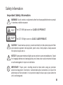
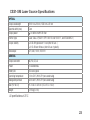
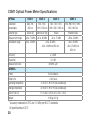
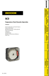
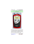
CSS1 Contractor Series Light Sources and
CSM1 Contractor Series Optical Power Meters
User’s Guide
CSS1 Contractor Series Light Sources and
CSM1 Contractor Series Optical Power Meters
User’s Guide
© 2006-2009, AFL Telecommunications, all rights reserved. CSM1-00-1000 Revision C, 2009-06-23
Specifications are subject to change without notice.
Limited Warranty
One Year Limited Warranty
All Noyes products are warranted against
defective material and workmanship for a
period of one year from the date of shipment
to the original customer. Any product found to
be defective within the warranty period will be
repaired or replaced by Noyes. In no case will
Noyes liabilities exceed the original purchase
price of the product.
Exclusions
The warranty on your equipment shall not apply
to defects resulting from the following:
• Unauthorized repair or modification
• Misuse, negligence, or accident
CE Information
These instruments have been
designed and tested to comply
with the relevant sections of
any applicable specifications including full
compliance with all essential requirements of
all applicable EU Directives.
Returning Equipment
To return equipment, please contact Noyes
to obtain additional information and a Service
Request (S.R.) number. To allow us to serve
you more efficiently, please include a brief
description specifying the reasons for the return
of the equipment.
AFL Telecommunications
Noyes Test & Inspection
16 Eastgate Park Road
Belmont, NH 03220
Phone: 800-321-5298
603-528-7780
Fax:
603-528-2025
Contents
Safety Information
Important Safety Information............................................. III
Section 1: General Information
Introduction...................................................................... 2
Contacting Noyes Customer Service.................................. 2
Unpacking and Inspection................................................. 2
Recommended Accessories.............................................. 3
Section 2: Functional Description
CSS1 Series Light Sources............................................... 4
CSM1 Series Optical Power Meters................................... 6
Front Panel Features.................................................... 6
Display Readings.......................................................... 8
Section 3: Applications
Measuring Optical Power.................................................. 10
Testing Fiber Links........................................................... 12
Step I - Set the Reference (One Jumper Method)........... 12
Step II - Verify Test Jumpers ........................................ 14
I
Step III - Measure Link Insertion Loss............................ 16
Section 4: Maintenance
Battery Replacement........................................................ 18
Cleaning Optical Ports...................................................... 18
To Clean CSS1 Optical Port.......................................... 20
Section 5: Specifications and Accessories
CSS1-MM LED Light Source Specifications....................... 22
CSS1-SM Laser Source Specifications.............................. 23
CSM1 Optical Power Meter Specifications......................... 24
II
Safety Information
Important Safety Information
!
WARNING! Use of controls or adjustments other than those specified herein may result
in hazardous radiation exposure.
The CSS1-MM light source is a CLASS I LED PRODUCT.
The CSS1-SM light source is a CLASS I LASER PRODUCT.
!
CAUTION! To avoid serious eye injury, never look directly into the optical outputs of fiber
optic network equipment, test equipment, patch cords, or test jumpers. Always assume
that optical outputs are on.
!
NOTICE! Noyes power meters and light sources contain no user serviceable parts. Except
for changing batteries and cleaning optical ports, these units must be returned to Noyes
or authorized agents for repair and calibration.
!
IMPORTANT! Proper care in handling should be taken when using any precision
optical test equipment. Scratched or contaminated optical connectors can impact the
performance of the instrument. It is important to keep the dust caps in place when the
unit is not being used.
III
Section 1: General Information
Introduction
The purpose of this User’s Guide is to explain how to use and maintain Noyes test equipment.
Please check our web site at www.AFLtele.com/go/Noyes for updates to this manual, software
updates, and additional application information. If you have any questions about your instruments
and recommended accessories, or if you need technical or sales support, please contact Noyes
Customer Service.
Contacting Noyes Customer Service
You may call Noyes Customer Service between 8 a.m. and 5 p.m., United States Eastern Time,
as follows:
Phone:
800-321-5298 (North America)
603-528-7780
Fax:
603-528-2025
Email:
[email protected]
Unpacking and Inspection
These instruments have been carefully packed in accordance with standard shipping procedures.
Examine the equipment for damage that may have occurred during shipment. If you find any
2
damage, please contact Noyes.
Recommended Accessories
You will need fiber optic test jumpers to connect instruments to the fiber optic system under test.
A test jumper must have the same core and cladding size as the fiber under test. The connector
at one end of the test jumper must mate with the optical port on each instrument. The connector
on the other end must mate with the fiber optic system under test.
A Connector adapter is required to mate fiber optic test jumpers.
Optical ports and connector end faces must be kept free from dirt or other contaminates to ensure
accurate measurements and operation.
For cleaning connector end faces on light sources, test jumpers, and in fiber frames or adapters,
use optical quality cleaning fluid such as AFL FCC2 connector cleaning fluid and AFL CCT molded
cleaning tips.
For cleaning an optical power meter port and adapter caps, use lint-free optical cleaning wipes such
as AFL FiberWipes and optical quality cleaning fluid such as AFL FCC2 connector cleaning fluid
(or IPA - Reagent Grade Isopropyl Alcohol 99% or better) and a can of filtered compressed air.
Visit our web at www.AFLtele.com/go/Clean for more information.
3
Section 2: Functional Description
CSS1 Series Light Sources
Output port 1
CSS 1
Display 2
-.0.0.00
-00.00
Tone
[Tone/CW] key 3
CW
uW
dBm
nm
Hz dBm
nm Ref
λ ID
Tone
5 [Backlight] key
[Power] key 4
Figure 2-1: Front Panel Features.
4
6 [l]- wavelengths key
CSS1 Model Features
Figure 2-1 illustrates the CSS1 model features described below.
1 Output port - Emits either continuous (CW) or modulated with one of four tone frequencies
(270, 330, 1000, 2000 Hz) light. This output port is equipped with a UCI base and adapter.
2 Display - Shows the enabled Wavelength [nm] and Tone frequency [Hz]. Also, the [Low
battery] indicator will be displayed to identify a low battery condition.
Enabled wavelength
Tone frequency
Tone
1300
nm
270
Hz
Low battery indicator
3 [Tone] key - Tone select key. Press this key to cycle through the available tone frequencies
or switch to the CW mode.
4 [Power] key - Press and hold for 2 sec. to turn the CSS1 on, press again to turn it off. Press
and hold during power up until the letter [AP] is displayed to enable the Auto-off feature.
5 [Backlight] key - Press this key to toggle the Backlight on or off.
6 [λ - Wavelength] key - Press this key to toggle between two wavelengths.
5
CSM1 Series Optical Power Meters
Front Panel Features
Adapter cap 2
1 Optical input adapter cap mount
CSM 1
Display 3
-.0.0.00
-00.00
Tone
[dB/dBm/µW] key 4
CW
uW
dBm
nm
Hz dBm
nm Ref
λ ID
µW
Set Ref
dB
dBm
Ref
[Power] key 5
6 [Wavelength/
Backlight] key
Figure 2-2: Front Panel Features.
6
7 [Set Reference] key
Front Panel Features
Figure 2-2 illustrates the CSM1 model features described below.
1 Optical input (adapter cap mount) - Accepts Noyes thread-on adapter caps.
2 Adapter cap - The CSM1 must be equipped with an adapter cap. Caps for different connector
styles are available from Noyes.
3 Display - Shows measured power [dBm or µW] or insertion loss [dB], enabled wavelength,
and tone frequency [Hz] if detected. Also, the [Low battery] indicator will be displayed to
identify a low battery condition.
4 [dB/dBm/µW] key - Provides two functions as follows:
• Press the key to toggle test readings between insertion loss in [dB] and power in [dBm].
• Press and hold the key until the word [HELD] is displayed to view power in [µW].
5 [Power] key - Provides two functions as follows:
• Press and hold the key for 2 sec. to turn the CSM1 on. Press again to turn it off. The unit
will turn off automatically five minutes after the last key press.
• Press and hold the key during power up until the letter [P] is displayed to disable the [Auto
Off] feature.
6 [λ - Wavelength/ Backlight] key - Provides two functions as follows:
7
• Press the key to cycle through the calibrated wavelengths.
• Press and hold the key until the word [HELD] is displayed to toggle the Backlight on or
off.
7 [Ref/Set Ref] key - Provides two functions as follows:
• Press and release the key to display the stored reference level for the currently selected
wavelength.
• Press and hold the key until the word [HELD] is displayed to store the currently measured
level as the new reference level. Once the new reference is set, the CSM1 switches to the
loss [dB] measurement mode.
Display Readings
Figures 2-3 illustrates the CSM1 display readings described below.
1 Test measurements field -  This field displays various test measurements as follows:
• Displays measured power [dBm or µW] or insertion loss [dB]. If power or loss is too high
or low for the CSM1 to measure, this field will display [HI] or [LO].
• If the reference power level is set for the currently enabled wavelength, this field will display
the reference value. To see the reference value, press and release the [Ref] key. Reference
value will be displayed briefly (for about 3 seconds), and then Display will revert to test
readings.
2 Wavelength/frequency field -  This field displays the currently enabled wavelength, which
8
will alternate with modulation frequency if detected.
3 Tone/CW/Battery status field -  This field displays [Tone] label to indicate the presence of
one of the 4 modulation frequencies, [CW] label to indicate no tone, and a battery icon used
to indicate the Low battery state - battery requires replacement.
1
-.8.8.88
2
-88.88
3
Tone
µW
dB (dBm)
Hz
nm
CW
Figure 2-3: Display Readings.
9
Section 3: Applications
!
It is important to keep all optical connections and surfaces free from dirt, oils, or
other contaminants to ensure proper operation. Always clean all test jumpers before
conducting the test procedures outlined in this Guide (see Section titled “Maintenance”
for details).
Measuring Optical Power
Figure 3-1 illustrates the following procedures.
1 Turn on the CSM1 optical power meter.
2 Select the appropriate fiber optic test jumper. The fiber type of this jumper must be the same
as the fiber type normally connected to the output being measured.
3 Mount the appropriate adapter cap on the CSM1 optical input. This adapter cap must match
the connector on the end of the test jumper you will connect to the CSM1.
4 Connect one end of the test jumper to the CSM1 adapter cap and the other end to the optical
output to be measured.
5 Press the [ λ ] key to select the calibrated wavelength that matches the nominal wavelength
of the source being measured.
6 If the CSM1 is presently measuring loss [dB], press and release the [dB/dBm] key to display
power in [dBm], or press and hold to display power in [µW].
10
Fiber optic equipment
Output
Input
4
3
Adapter cap
4
CSM 1
-.0.0.00
-00.00
Tone
6
1
CW
2
uW
dBm
nm
Test jumper
Hz dBm
nm Ref
λ ID
µW
Set Ref
dB
dBm
Ref
5
Figure 3-1: Measuring Optical Power
11
Testing Fiber Links
Step I - Set the Reference (One Jumper Method)
Figure 3-2 illustrates the following procedures.
1 Turn on the CSM1 optical power meter and CSS1 light source. Allow the CSS1 light source
to stabilize (minimum of 2 minutes).
2 Set both instruments to the desired test wavelength.
3 Select the appropriate fiber optic transmit and receive test jumpers. The fiber type of these
jumpers must match the fiber type of the link to be tested.
4 Wrap and secure the transmit jumper five times around the appropriate diameter mandrel.
Note: Clean both ends of the transmit jumper.
5 Connect the transmit jumper to the CSS1 output port.
6 Mount an adapter cap on the CSM1 that matches the free connector on the transmit
jumper.
7 Connect the free end of the transmit jumper to the CSM1. If necessary, press the [dB/dBm]
key to display optical power in [dBm].
8 If measured output power is outside of the normal range (specified by manufacturer), clean
all fiber connections or replace the transmit jumper. Repeat steps 5 - 7.
9 To set the reference level at the current wavelength perform the following steps:
12
• On the CSM1, press and hold the [Ref/Set Ref] key until the word [HELD] is displayed to
store the currently measured level as the new reference level.
• Once the new reference is set, the CSM1 switches to the loss [dB] measurement mode.
The CSM1 should display [0 dB] ± 0.05 dB.
Note: You may press the [Ref/Set Ref] key to display the stored reference level for the currently
selected wavelength.
mandrel wrap
4
transmit jumper
7
5
6
0 dB
CSS1
CSM1
Figure 3-2: Set the Reference.
13
Step II - Verify Test Jumpers
Figure 3-3 illustrates the following procedures.
10 Disconnect the transmit jumper from the CSM1.
Note: Do not disturb the transmit jumper at the CSS1 end.
11 If necessary, change the CSM1 adapter cap to match the connector on the receive jumper
that will be connected to the CSM1.
Note: Clean both ends of the receive jumper.
12 Connect the receive jumper to the CSM1.
13 Mate the free ends of the transmit and receive jumpers using the appropriate adapter.
14 Verify that the insertion loss of this mated connector pair is under 0.75 dB, the maximum
allowed by the TIA (Noyes recommends 0.4 - 0.5 dB typical), as follows:
• Observe the displayed power level. This is the mated connector pair insertion loss of the
test jumpers in [dB].
15 If the insertion loss is not acceptable, disconnect the transmit and receive jumpers at the
adapter.
• Clean the free ends of both test jumpers
• Repeat steps 13 & 14.
• If the insertion loss is still not acceptable, replace test jumpers and repeat steps 1-14.
14
16 If the insertion loss is acceptable, disconnect the transmit and receive jumpers at the
adapter.
17 Move the CSM1 and CSS1 to opposite ends of the link to be tested.
Adapter
Transmit jumper
Receive jumper
Mandrel wrap
13
12
11
Do NOT disturb
this connection
New adapter cap
(if necessary)
0.4 dB
CSS1
CSM1
Figure 3-3: Verify Test Jumpers.
15
Step III - Measure Link Insertion Loss
Figure 3-4 illustrates the following procedures.
18 Connect the free ends of the transmit and receive jumpers to the link under test.
Note: Clean jumper end that connects to patch panel prior to every test.
19 CSM1 will measure and display the insertion loss of the link under test.
20 Record link insertion loss at the current test wavelength.
21 Repeat steps 18-20 for all links to be tested at the current wavelength.
16
Patch panel
Patch panel
Receive jumper
~
~
Transmit jumper
Mandrel wrap
Link under test
2 dB
CSS1
CSM1
Figure 3-4: Measure Link Insertion Loss.
17
Section 4: Maintenance
Battery Replacement
To replace batteries:
1 Remove the battery compartment cover located on the back of the instrument.
2 Replace the discharged batteries.
3 Replace the battery compartment cover.
Cleaning Optical Ports
!
CAUTION! Before conducting the following procedures be sure to have the instruments
turned OFF.
Optical ports must be kept free from dirt or other contaminants to ensure accurate measurements
and operation. Always clean all test jumpers before conducting the test procedures outlined in this
Guide. It is important to keep dust caps in place when instruments are not being used.
For cleaning connector end faces on CSS1 light sources, test jumpers, and in fiber frames or
adapters, use optical quality cleaning fluid such as AFL FCC2 connector cleaning fluid and AFL
CCT molded cleaning tips.
For cleaning CSM1 optical ports and adapter caps, use lint-free optical cleaning wipes such as
AFL FiberWipes and optical quality cleaning fluid such as AFL FCC2 connector cleaning fluid (or
IPA -Reagent Grade Isopropyl Alcohol 99% or better) and a can of filtered compressed air.
18
To Clean CSM1 Optical Port
1 Unscrew the adapter cap from the adapter cap mount.
2 Use lint-free optical cleaning wipes such as AFL FiberWipes and optical quality cleaning
fluid such as AFL FCC2 connector cleaning fluid.
Note: if using isopropyl alcohol (IPA), be sure to use 99% pure IPA that has not been
contaminated.
• Dampen a portion of the wipe with the cleaning fluid.
• Gently wipe the exposed optical port starting with the wet section of the wipe and pulling
it to the dry section.
Note: Starting with the wet cleaning and finishing in the dry improves cleaning action,
reduces static buildup, and finishes with the end-face dry.
3 Using a can of filtered compressed air (held vertically), blow out any contaminants from the
adapter cap.
4 Replace the adapter cap once the cleaning is complete.
19
To Clean CSS1 Optical Port
If using AFL CCTS cleaning tips and FCC2 cleaning fluid:
1 Leaning the FCC2 can back (30°), press the button on the FCC2 to fill the well.
2 Dip the CCTS tip into the well of the FCC2 to dampen the tip with optical cleaning fluid.
3 Place the damp tip in the adapter until it touches the ferrule.
4 Rotate the tip clockwise 10 revolutions while applying varying pressure to create a gentle
pumping action where the tip contacts the ferrule.
5 Discard the CCTS stick after using both tips.
If using AFL ACT cleaning sticks
1 Place the ACT tip in the adapter until it touches the ferrule.
2 Ensure that stick is held straight when inserting into sleeve.
3 Apply sufficient pressure (approx. 600-700g) to ensure ferrule is a little depressed in
sleeve.
4 Rotate stick clockwise 4-5 times, while ensuring direct contact with ferrule end-face is
maintained.
5 Discard the ACT stick after each use.
20
Repair and Calibration
Repair of the Noyes test equipment in the field is NOT recommended.
Calibration is recommended every 12 months. Noyes’ Calibration Department is in compliance
with ANSI/NCSL Z540-1, ISO 10012-1, MIL STD 45662A, ISO Guide 25 and traceability to the
National Institute of Standards and Technology. Call Customer Service to obtain a Service Request
(S.R.) number before sending units in for calibration.
21
Section 5: Specifications and Accessories
CSS1-MM LED Light Source Specifications
Optical
Output wavelength
850 nm ±20 nm
1300 nm +40/-60 nm
Spectral width (max)
35 nm
170 nm
Output power
Emitter type
Output stability
Tone output
General
Output connector
Power
Battery life
-20.0 dBm into 62.5/125 fiber
LED, Class I FDA 21 CFR 1040.10 and 1040.11, IEC 60825-1: 2007-03
± 0.1 dB over 1 hour (after 30 sec typically)
± 0.15 dB over 8 hours (after 30 sec typically)
270, 330, 1000, 2000 Hz
SC
2 x AA batteries
30 hours typical
Operating temperature
-10 to 50°C, 90% RH (non-condensing)
Storage temperature
-30 to 60°C, 90% RH (non-condensing)
Size (H x W x D)
11.4 x 6.4 x 3.2 cm (4.5 x 2.5 x 1.3 in)
Weight
All specifications at 25°C
22
0.18 kg (0.4 lb)
CSS1-SM Laser Source Specifications
Optical
Output wavelength
1310 nm ±20 nm, 1550 nm ±20 nm
Spectral width (max)
5 nm
Output power
0.0 dBm into 9/125 fiber
Emitter type
Laser, Class I (FDA 21 CFR 1040.10 and 1040.11, and IEC 60825-1)
Output stability
± 0.05 dB typical over 1 hour (after 30 sec. )
± 0.15 dB over 8 hours (after 30 sec. typically)
Tone output
270, 330, 1000, 2000 Hz
General
Output connector
SC, FC, ST, LC
Power
2 x AA batteries
Battery life
75 hours typical
Operating temperature
-10 to 50°C, 90% RH (non-condensing)
Storage temperature
-30 to 60°C, 90% RH (non-condensing)
Size (H x W x D)
11.4 x 6.4 x 3.2 cm (4.5 x 2.5 x 1.3 in)
Weight
0.18 kg (0.4 lb)
All specifications at 25°C.
23
CSM1 Optical Power Meter Specifications
Optical
CSM1-1
Calibrated
wavelengths
660, 780,
850 nm
850, 1300,
850, 1300, 1310,
1310, 1550 nm 1490, 1550, 1625 nm
Detector type
CSM1-2
CSM1-3
CSM1-4
850, 980,1310, 1490,
1550, 1625 nm
Silicon (Si)
Germanium (Ge)
InGaAs
Filtered InGaAs
Measurement range
+6 to -70 dBm
+6 to -60 dBm
+6 to -70 dBm
+26 to -50 dBm
Tone detect range
+6 to -45 dBm
+6 to -50 dBm
+6 to -45 dBm for 850 nm
Accuracy*
± 0.3 dB
Resolution
0.01 dB
Measurement units
General
Power
Battery life
dB, dBm, μW
2 x AA batteries
> 300 hours
Operating temperature
-10 to 50°C, 90% RH (non-condensing)
Storage temperature
-30 to 60°C, 90% RH (non-condensing)
Size (H x W x D)
11.4 x 6.4 x 3.2 cm (4.5 x 2.5 x 1.3 in)
Weight
0.18 kg (0.4 lb)
*Accuracy measured at 25ºC and -10 dBm per N.I.S.T. standards.
All specifications at 25°C
24
+6 to -30 dBm
+6 to -25 dBm for
850 nm
Thank you for choosing Noyes Test & Inspection
16 Eastgate Park Road
Belmont, NH 03220
Phone:800-321-5298
603-528-7780
Fax: 603-528-2025
www.AFLtele.com/go/Noyes
N OY E S
ISO
9001
C E RT I F I E D