1
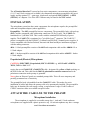
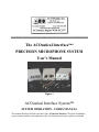
The ACOustical Interface(tm)
PRECISION MICROPHONE SYSTEM
User's Manual
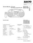
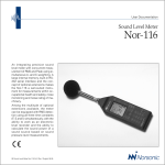
Figure 1
ACOustical Interface System™
SYSTEM OPERATION - USERS MANUAL
This manual describes the basic operaton of the ACOustical Interface ™ System. Installation,
system controls and the actual operation of the ACOustical Interface(tm) system are included.
The ACOustical Interface™ system has four major components: a measurement microphone;
(1/4, 1/2 and 1 Inch versions are available), the companion microphone preamplifier; the power
supply; and the optional "G" - gain stage, windscreen, and optional PS9 (110VAC). or PS29
(220VAC) AC adaptors. Use of the SPL Calibrator may be found in the 511E manual.
INSTALLATION
The microphone system has three main components: the microphone capsule; the preamplifier/
cable and microphone adaptor (where applicable).
Preamplifier - The 4012 preamplifier has two components. The preamplifier body with end-cap
(EC2), and the companion cable with mating connectors (XLR or Lemo). The CA4012-5 is
terminated in a 5 pin Male XLR. This is mates with the standard PS9200 family of power
supplies. The CA4012-7L is terminated in a 7 pin Male Lemotm connector. The CA4012-L7
pinout is compatible with the PS9200L7 (2 channel) and PS9204L7 channel) power supplies. It
is also compatible with Hewlett Packard, Norsonic and Bruel and Kjaer instruments equipped
with the mating connector.
4016 - 1/4 Inch preamplifier consists of the 4012 and companion cable and the AD0016 1/4 to
1/2 Inch adaptor.
4022 - 1 Inch preamplifier consists of the 4012 and companion cable and the AD0122 1 Inch to
1/2 Inch adaptor.
Prepolarized (Electret) Microphones
CAUTION: ELECTRET (Prepolarized) MIC CAPSULES e.g. ACO Pacific's MK224,
7052S, 7051S or B&K 4155
require the special CA4012-5E (CA4012L7E) cable - designated by yellow or black marking on
the XLR/Lemo end. This cable has the 200 Vdc polarization conection removed and is the
polarizaton connection at the preamp is grounded.
Never place an Electret Capsule on a standard preamp/cable. This will cause temporary and
possibly permanent loss of sensitivity.
The preamplifier body is detachable from the CA4012XX cable. This makes for easier
installation of cables and allows the preamp cable to be permanently installed. The preamplifier
body may be detached for safe storage, testing, or replacement. Longer CA4012 cables or
CE4012 extension cables are available on special order.
ATTACH THE CA4012-XX TO THE PREAMP.
Microphone Installation
The microphone is supplied in a reusable storage box. 1 inch and 1/2 inch condenser
microphones are supplied with a plastic protective cap. 1/4 inch microphones may have a storage
stand. Save these accessories.
All ACO Pacific measurement microphones have an individual "Birth Certificate". The
certificate provides actual measured sensitivity data and frequency response curves for the
specific capsule. RETAIN THIS CHART.
The plastic cap provided on some capsules protects the stored microphone from accumulation of
dust and dirt on the diaphragm. The cap should be stored in the microphone box as may the 1/4
inch mic stand.
INSTALLING THE MICROPHONE CAPSULE The microphone end of the 4012 preamplifier is protected by a machined metal cap (EC2). This
cap protects the preamplifier input from dust, oil and physical damage when the microphone is
not installed.
To remove - simply unscrew the cap from the preamp body.
Save the preamp cap. The cap may be stored in the microphone box with the microphone cap.
1/2 INCH MICROPHONES
Carefully install the selected microphone capsule on the face of the preamplifier - DO NOT
OVERTIGHTEN - YOU MAY PERMANENTLY DAMAGE ANY PRECISION MIC BY
EXCESSIVE FORCE - FINGER TIGHT IS ADEQUATE!
1/4 INCH MICROPHONES
An AD0016 1/4 to 1/2 inch adaptor is required. Place the AD0016 preamp adaptor on the face of
the preamp. The ACO Pacific 4016 Preamp is this combination. Carefully place the 1/4 inch mic
capsule on the end of the 1/4 inch adaptor. DO NOT OVERTIGHTEN!
1 INCH MICROPHONES
An AD0122 1 inch to 1/2 inch adaptor is required. Slide the AD0122 1 Inch Mic to 1/2 inch
preamp adaptor over the preamplifier from the microphone end and thread in place. This is the
ACO Pacific 4022 Preamp combination. Mount the mic capsule on the adaptor/preamp
combination. DO NOT OVERTIGHTEN!
The dust cap must be removed when making
measurements.
MICROPHONE GRIDS - DO NOT REMOVE - It Is Not Necessary
The grids of most ACO Pacific microphones are removable. This is not necessary for most
measurements. The microphone is designed for use with the grid. Removal will not give you
better or higher or lower readings. The FREE FIELD response curve supplied with Free Field
capsules assumes the grid is on the microphone capsule. Removing the grid does change the high
frequency response.
If you must remove the grid do so with care . It is very easy to crease the 2u thick diaphragm or
even tear it.
In ALL cases DO NOT OVERTIGHTEN the grid or the microphone. The fine threads of both
make this very easy.
PS9200 OPERATION
The PS9200 utilizes a standard L1604 - 9 Vdc Alkaline Transistor Radio Battery. The Battery
Compartment is located on the bottom of the case below the BNC cable connectors.
The Power Switch is located on the bottom front of the unit below the Preamp input connectors.
The Power Switch is a "LOCKING TOGGLE" TO Turn ON or to Turn OFF- GENTLY
PULL OUT ON THE HANDLE BEFORE TOGGLING THE SWITCH. Up is "ON" and Down
is "OFF".
INSTALLING BATTERY - Not required for AC operation
First TURN OFF the PS9200 .
Turn over the unit. Slide open the compartment door and connect the battery to the polarized
connector in the compartment. Use caution - DO NOT Reverse the Battery Connections. If you
have accidently left the unit turned on - you will blow the 250 mA fast blow fuse inside the
PS9200.
Replace the door. BATTERY LIFE FOR A SINGLE PREAMP OPERATION IS 50
HOURS - TYPICAL. As with all battery powered devices temperature, type of battery, and age
of the battery effect operational battery life. Battery life with the 4012HP (higher current
version) is much less - about 10 - 12 hours. Battery life for the PS9250 is similarly reduced.
AC OPERATION - 110 Vac (PS9), 220 Vac (PS29) - Plugging your PS9 or PS29 into the
external power connection on the side of the PS9200 disconnects the battery (removal of the
battery is not necessary). The PS9200 automatically disconnects the battery when external DC is
supplied. You do not need to install a battery for AC Only operation.
OPERATION
With a 9 Vdc battery installed or an AC Adaptor (PS9 or PS29) connected you are now ready to
connect the microphone preamplifier and output BNC cables.
ATTACHING THE 4012 or similar Preamp - Your BNC signal cable should then be attached to
the BNC connector directly inline with the preamp cable. The label designates these channels
"A" and "B".( Note the PS9204L7 has only A&B markings. Designate the remaining two
channels "C" and "D" as you wish.
The Power Switch is located on the bottom front of the unit - below the Preamp input
connectors. The Power Switch has a "LOCKING TOGGLE" TO Turn On - GENTLY
PULL OUT ON THE HANDLE BEFORE TOGGLING THE SWITCH UPWARDS ("ON").
A "Flashing LED" indicates power is applied. "FLASHING" also indicates the battery or
supply voltage is above 6.2 Vdc. A STEADY LED indicates the battery voltage is low. You will
have about 1 -2 hours (with 1 preamp) of useful battery life left when the LED is on "STEADY".
Replace the battery as soon as possible. You should not see a steady LED during normal AC
Adaptor (PS9 or PS29) operation
"TURN ON" TIME - 2-4 minutes - The extended low frequency response of the microphones
and the preamplifier result in long turn on times for the ACOustical Interface™ System.
Typically this will be about 2 - 4 minutes.
IMPORTANT - THE PS9200 HAS BEEN DESIGNED TO REDUCE THE 200 Vdc
POLARIZATION VOLTAGE WHEN NO PREAMPS ARE PLUGGED IN TO THE SUPPLY.
IT WILL TAKE AT LEAST 1 - 2 MINUTES TO STABILIZE AFTER THE PREAMP IS
INSTALLED.
YOU WILL NOT READ 200 Vdc ON PIN 3 OF THE SPARE XLR CONNECTOR. THE
OUTPUT RESISTANCE OF THE CIRCUIT IS 11 MEGOHMS. THIS IS TO PROTECT
YOU - THE USER.The typical DVM (Digital Voltmeter) has 10 MegOhms of input resistance,
creating a voltage divider. You may read about 60 to 100 Vdc. This is not an accurate reading
CAUTION - While the input to the 4012 Preamp is protected against electrical discharge - use
care when installing and removing the microphone. If you accidently touch the center pin of the
preamp to the shield or ground the 200 Vdc polarization charge will be removed and take about 2
minutes to restabilize. A slow increase in the sensitivity will be noticed as the voltage returns.
"G" - Gain Option
The "G" option provides two independent fixed gain (or buffer) stages. Factory installed the
gain is preset - to order - by the factory. Standard gains are 20 dB and 40 dB. Switches for each
channel are located on the back of the PS9200 next to the BNC signal output connectors. A color
dot or label next to the switch indicates the preset gain of the individual channel.
In the "Direct" position signals from the 4012 or other preamp are directly fed to the BNC
through the internal decoupling cap. The maximum signal limits in this mode are determined by
the preamplifier and the preamp 28 Vdc operating voltage (50 Vdc with the PS9250).
The maximum output voltage swing of the "G" option is determined by the DC supply voltage of
the PS9(PS29). This is typically 3.3 Vrms for a 13.5 Vdc source.NOTE: Operation from the
internal 9Vdc battery is not recommended.
The ACOustical Interface™ and microphones are precision measurement equipment.
Designed for the rigors of field use they will last for many years of accurate stable measurements
if properly treated and maintained.
Acoustic Signal Polarity - A Reminder
In some measurement applications ,such as loudspeaker testing, knowing the absolute polarity of
the acoustic wave is important. The traditional polarized measurement microphone has a
positive polarization voltage on the back plate. This is an artifact of the positive plate (anode)
voltage found in tube (valve) designs. The output of the traditional measurement microphone
preamplifier both tube and solid-state is non-inverting. These designs are usually a cathode
(tubes) or JFET source followers.
As a result of the positive polarization voltage - positive going acoustical waves result in a
negative going electrical signals from the microphone and preamplifier. This does not affect the
accuracy of the measurements but does need to be taken into account in some applications
On the other hand - Electret (prepolarized) microphones have a negative polarization voltage
(electrons stored in the electret material). Positive going acoustic waves result in the electron
charge being reduced on the backplate - thus a positive going output voltage is seen. Again, the
measurement accuracy is not affected.
It is convention for POLARIZED MEASUREMENT MICROPHONES on Non-Inverting
Preamps to output:
NEGATIVE GOING SIGNALS FOR POSITIVE GOING SOUND PRESSURE
For ELECTRET MICROPHONES on Non-Inverting Preamps:
POSITIVE GOING SOUND PRESSURE RESULTS IN POSITIVE GOING SIGNALS
The preamps of ACO Pacific, Bruel and Kjaer and others are Non-Inverting
Optional Equipment
SC1 and SC2 Custom Storage Cases
The SC1 - non-locking and SC2 locking storage cases have die cut foam inserts designed
specifically for the storage and transport of the PS9200, Microphones, Preamps and their cables,
WS1 windscreen, PS9 or PS29 Adaptors, Microphone Adaptors, Spare Batteries, and the 511E
calibrator. The SC1 is provided as part of the PS9200KIT. The SC2 may be specified as an
option.
WS1 - 3" Windscreen
The WS1 windscreen is designed to reduce wind noise in outdoor applications. The material was
selected to minimize attenuation of sound to beyond 20 kHz. The WS1 may also be used
additional mechanical protection for the microphone. It will protect the microphone diaphragm
from stray particles, oils and other materials and act as a bumber in the case of a mishap. The
WS1 is included in the PS9200KIT.
WS7 - 7" Windscreen
The WS7 windscreen was designed for higher velocity wind environments, like thjose found in the desert of the
Southwest US. The WS1 is adequate for most applications.
DM2 Series of Dummy Microphones
The DM2 Series of dummy microphones permits the connection of electrical signals to the input
of the 4012 preamplifier. The DM2-22 dummy microphone has a 22 pF coupling capacitor to
simulate a typical 1/2 inch mic capsule. For more information read the Dummy Microphone
Users Manual.
Return to Home Page
ACO Pacific, Inc.
2604 Read Ave.
Belmont, CA 94002, USA
(650) 595-8588 Fax: (650) 591-2891
e-mail: [email protected]
ACOustics Begins With ACOtm
©1998 ACO Pacific, Inc. All Rights Reserved