1
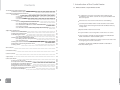
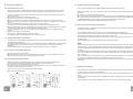
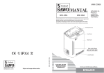
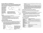
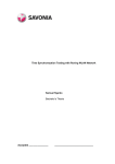
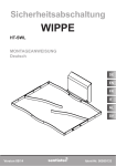
MANUAL
NIMC-90N
Nimbus Combi
Super Nimbus Combi NIMC-150N
NIMC-105N
NIMC-120N
NIMC-180N
Congratulations on your purchase of a SAWO heater/steam generator.
Please read the manual carefully before using the product.
The Safety Temperature Sensor has to be mounted above the heater.
Check the manual of the external control unit for further instructions.
www.sawo.com
[email protected]
NIMC_ML_S(EnV10608)
PX4
15.0 kW
18.0 kW
9.0 kW
10.5 kW
12.0 kW
ELECTRIC SAUNA HEATER /
STEAM GENERATOR
Not for use in the USA, Canada and Mexico.
Subject to change without notice
ENGLISH
1. Introduction of the Combi Heater
Contents
1.1. Nimbus Combi / Super Nimbus Combi
1. Introduction of the Combi Heater
1.1 Nimbus Combi/ Super Nimbus Combi
2. Assembly and Installation Instructions
2.1 Assembly
2.1.1 Loading soapstones into the heater
2.1.2 Drain
2.1.3 Steamer Cover
2.2 Installation
2.2.1 Locating the Nimbus Combi Heater
2.2.2 Electrical Wiring and Installation
2.2.3 Installation of External Control Unit and Sensor
2.2.4 Sensor Location
2.2.5 The Effect of Moisture During Transport and Storage
2
2
3
3
3
4
4
5
5
7
8
9
9
3. Operating Instructions
3.1 How to Load the Stones
3.2 Using the Combi Heater
3.3 Producing the Steam
3.3.1 Kind of Water to Use
3.4 Using the Steamer with Manual Refill
3.4.1 Filling the Water Compartment
3.4.2 Low Water Level
3.5 Using the Steamer with Built-in Automatic Refill System
3.6 Draining and Cleaning the Water Tank
3.7 Using Scents
9
9
10
10
10
11
11
11
11
12
12
4. Precautions
13
5. Troubleshooting
13
6. Technical Data
13
7 Spare Parts
14
8. The Sauna Room
8.1 How to Use the Sauna
8.2 Temperature of the Sauna Room
8.3 Drying the Sauna Room After Use
8.4 Ventilation of the Sauna Room
8.5 Hygiene Inside the Sauna Room
8.6 Parts and Insulation of the Sauna Room
8.7 Combi Heater Output
15
15
15
15
15
16
16
16
1
A combination of a heater and steamer with Scent Basins and
probably the most reliable steamer due to its patented Water Level
Detection System.
Allows users to choose from normal sauna to steam bathing.
Its metal parts and Water Tank are made of stainless steel and the
unique design of the heating elements makes the Water Tank easy
to keep clean.
Operated with an external control unit.
Its optional fiber-coated casing makes it safer and cool to touch.
Savonia Combi as available in 9.0kW, 10.5kW and 12.0kW, Manual
Refill or with Built-in Automatic Refill System.
The Super Savonia Combi has two tanks located on both sides of the
heater giving more steam to the bather.
Available in 15.0kW and 18.0kW, Manual Refill or with Built-in
Automatic Refill System.
2
2. Assembly and Installation Instructions
2.1. Assembly
2.1.1 Loading soapstones into the heater
It is recommended that all soapstones should be rinsed to remove any stains or dust that can cause
unpleasant odour during the first few times of using the heater.
Follow stone piling instructions according to the illustration Fig.1. Avoid piling them while the
heater is on, as it can cause serious burns. Brush the water pockets and rinse with water after using
scents.
2.2.1 Drain
Ball valve is located
below the steam tank.
See illustration below.
Fig. 2
Unscrew the stones
below to locate the valve.
Remove the stones on
the front by
unscrewing it.
Set ball valve in
“Close” position if not
drained.
Fig. 1 Stone Assembly
Ball Valve in “close” position
C
B
D
2
1
2.1.2 Steamer Cover
• Follow the instructions given in Figure 2 in attaching or detaching the Steamer Cover
A
Fig. 2 Steamer Cover
4
C
Lift the steamer
cover and refill water.
D
3
1
B
A
2
3
Name Plate
4
Fig. 5 Minimum Safety Distances
2.2. Installation
MIN. 120
MIN. 110
2.2.1 Locating the Combi Heater
60
MIN. 160
MIN. 160
NIMC-120N
160
100
MIN. 2100
MIN.
MM
20
70
1400
130
MIN. 2100
MIN.
MM
20
1400
MIN. 130
Must be screwed directly
on the floor to prevent
from accidentally moving
the heater.
120
NIMC-105N
MIN. 130
NIMC-90N
Twist to adjust
height.
MIN.
MM
20
Fig. 4 Screwing the Combi Heater on the floor
MIN. 1900
50
1200
110
20
MIN.
MM
MIN. 120
MIN. 1900
MIN. 110
1200
• It is recommended that the Combi Heater is placed on the floor nearest to the door.
• For safety and convenience, follow the minimum safety distances as provided in Figure 5
and follow the cubic volumes given in Figure 11 (Technical Data).
• Do not install more than one heater, unless, you follow the special instructions
for twin-heater installations.
• In most countries, there is a law that requires heaters to be screwed on the floor as
provided in Figure 4.
NIMC-150N
NIMC-180N
NOTE: Remove the packaging from the heating elements before installing the heater as it
is only intended to protect them during shipment. Make sure that the Silica gel pack is
removed from the heater as the purpose of it is to get rid of the moisture during
shipment.
• A Combi Heater, when used, is naturally hot. Figure 5 shows the minimum safety
distances in installing heater guards.
5
6
2.2.2 Electrical Wiring and Installation
• Only a certified electrician must do the installation of the Combi Heater to ensure safety and reliability.
• Installation should be done according to applicable local regulations to ensure safety and reliability of
electrical connections. Wrong electrical connection can cause electric shock or fire.
• The connection cable insulation must be of rubber type, HO7RN-F, or its equivalent.
NOTE: Using a PVC-insulated wire as connection cable for the Combi Heater
is not allowed because this material easily becomes brittle when subjected to heat.
• For further assistance, refer to the electrical diagram in Figure 6.
Fig. 6 Electrical Diagram
Manual Refill
7
8
Auto Refill
2.2.3 Installation of External Control Unit and Sensor
• Refer to the external Control Unit Manual for its installation and connection to the Combi
Heater as well as the installation of the Temperature Sensors.
NOTE: An additional Contactor Unit is needed for 10.5kW, 12.0kW, 15.0kW and 18.0kW Combi
Heaters.
9
10
2.2.4 Sensor Location
• The Safety Temperature Sensor must be installed directly above the heater, 15cm below the
ceiling. Refer to Figure 7.
Fig. 8 How to Load the Stones
NO CERAMIC STONES
Fig. 7 Safety Sensor Location
SECTION VIEW
NOTE!
Heating element damage due to overheating caused by wrong kind of stones or stones which were
wrongly loaded into the heater is not covered by the factory warranty.
3.2. Using the Combi Heater
• Before turning on the Combi Heater, make sure that nothing else but stones are placed inside or
PERSPECTIVE
2.2.5 Effect of Moisture During Transport and Storage
• When doing a final inspection for the electrical installation of the Combi Heater, a
“leakage” may be detected when measuring the insulation resistance. This is because the
insulating material of the heating resistors has absorbed moisture from the air (during
transport and storage). The moisture will eventually be removed after several uses of the
heater.
NOTE: An additional Contactor Unit is needed for 10.5kW, 12.0kW, 15.0kW and 18.0kW
Combi Heaters.
near the unit. For more safety instructions, please refer to Part 4 – Precautions section of this
manual. Bad odor may be detected when using the Combi Heater for the first time. To remove the
smell, just ventilate the Sauna Room.
• It is important that you choose the correct power rating of the Combi Heater that will correspond
to your Sauna Room size. Part 6 (Technical Data) of this manual will help you to make the right
choice. A properly selected Combi Heater allows to reach the bathing temperature within an hour.
• If the heater power is too big for the Sauna Room, the room will heat up faster than the stones and
will cause the water thrown on the stones to go through the stone compartment too quickly. On
the other hand, if the heater power is too little for the Sauna Room, the water thrown on the
stones will not increase the humidity; instead, it will only cool the stones thus decreasing the
temperature inside the Sauna Room.
• Your Sauna Room must have suitable insulation and wall materials. Refer to Part 8 (The Sauna
Room) of this manual for guidance. The bathing temperature should preferably be within the
range of 65 to 85 degrees Celsius, while the Steamer is switched off.
3.3. Producing the Steam
3. Operating Instructions
3.1. How to Load the Stones?
• Stones are loaded into the Combi Heater so that enough energy will be stored to efficiently
vaporize the water thrown on them and maintain the correct humidity inside the Sauna Room.
• These stones must be replaced at least once a year or every 500 hours, whichever, occurs first.
• In removing the stones, stone crumbles (small pieces of stones that has broken off from the larger
• Throwing water on the stones increases the moisture level inside the Sauna Room and the heater
increases the temperature.
• The amount of water thrown on the stones determines the moisture content of the air.
• Three ladles of water at a time are enough to enjoy the Sauna. Throwing too much water on the
stones may cause scalding water to splash on the bathers, as the water may not evaporate
immediately.
• Make sure there is no one sitting near or next to the heater before throwing water on the stones.
ones due to frequent usage) must be removed as well.
• Refer to the Technical Data in Figure 11 for the required amount of stones.
NOTE: Never use the Combi Heater without the stones as it can cause fire. Use only stones
recommended by SAWO. The use of any other kind of stones may damage the heating elements
and will void your warranty. Also, never use ceramic stones or any other artificial stones.
• Before loading the stones into the Combi Heater, rinse them first to remove stains or dust that may
emit unpleasant smell when using the unit for the first time.
• Care must be taken in loading the stones and make sure that they will not block the air circulation
through the heater. Refer to Figure 8.
11
3.3.1. Kind of Water to Use
• Use only clean household tap water to throw on the stones.
• Do not use hard, ferrous or chlorinated water.
• Hard water causes white deposits on the stones and on the heater surface, and it also decreases
the heat accumulating property of the stones.
• On the other hand, if the water you are using is ferrous, a rusty layer will cover the heating
elements and other parts of the heater and will lead to corrosion.
• The use of seawater, chlorinated water and humus water can damage your Combi Heater and its
parts as well.
12
3.4. Using the Steamer with Manual Refill
3.4.1. Filling the Water Compartment
• Fill the Tank by pouring water through the holes designated for the Scent Basins.
• The amount of water poured can be monitored using the Water Level Indicator.
• The water should not exceed the 5-liter marking on the Level Indicator; otherwise it might spill on
the floor.
• If “FILL” is displayed on the external control unit, refill the Water Tank. Be careful in removing the
Scent Basins during bathing, as they will be hot to touch. Do not attempt to remove the Steamer
Cover, as it will be extremely hot to touch.
• Always make sure that there is a sufficient amount of water in the Water Tank before using the
Steamer.
3.4.2. Low Water Level
• The Combi Heater is equipped with a Low Water Level Detection System, which prompts the user
to refill water before the Water Tank runs dry.
• The Low Water Level Detection System will display “FILL” on the external control unit when only
about 1-liter water is left in the tank. A warning sound (buzzer-like) will also be emitted to catch
the user’s attention. The tank should then be refilled with water.
• If, despite the “FILL” message and warning buzzer, water is not refilled, the Steamer will eventually
run dry, which negatively affect the life time of the heating plate.
3.6. Draining and Cleaning the Water Tank
• The Water Tank should be emptied and cleaned after every use to ensure that always fresh and
clean steam is produced.
• Wait for the unit to cool down before draining the water.
• To drain the water, turn the Ball Valve handle at the bottom of the Steamer Tank counterclockwise
until water flows out of the tank. Provide a container to collect the water.
• For the Super Nimbus Combi, both tanks shall be drained.
• Every 500 hours of use or 6 months whichever comes first, disconnect the connection hose of the
two tanks and rinse with water to remove particles inside the hose that will cause water clog up.
• Do not forget to connect back the hose of the two tanks after cleaning. See Figure 9.
• Once the tank is completely drained, remove the Steamer Cover and clean the tank inside with a
household brush to remove impurities that have accumulated in the tank, and then rinse with
water.
• Do not use a steel brush as it might damage the tank wall or the bottom heating plate.
• Do not clean the water tank inside with a cloth to avoid hand injuries that may be caused by the
tank’s edges.
• To clean the tank’s separation plate, lift it up and clean it with water and a household brush. See
Figure 10.
Fig. 9 Connecting Hose
Fig. 10 Separation Plate
3.5. Using the Steamer with Built-in Automatic Refill System
• The Combi Heater is equipped with an automatic water refilling system that makes it possible to
produce the steam without refilling water manually.
• The Steamer Tank will automatically be refilled with water upon turning ON the control unit
and will be refilled with water automatically once the water level is already near the low-water
detection mark.
• As a security feature, if the Water Tank is not refilled automatically for any possible reason, the Low
Water Detection System will automatically turn off the Steamer. And the word “FILL” will be
displayed on the external Control Unit and a warning sound (buzzer-like) will be emitted. (Refer to
Part5 Troubleshooting)
NOTE:
Make sure that there is enough supply of water and the water supply pressure must be in the
range of 1 to 2 bar to have a smooth automatic refill system function and check the water
connection that it is properly connected to the water inlet of the steamer before turning ON the
steamer ( Refer to Figure 1 ).
Connection Hose
• Finally, flush the tank with water and close the Ball Valve by turning its handle clockwise.
• Before using the Steamer again, do not forget to refill the Water Tank (not applicable for Built-in
Automatic Refill System).
• Do not let the Water Tank run dry as an alternative method of draining the water, this will shorten
the life span of the Steamer hot plate.
• It will not be helped that impurities from the water (e.g. lime) will accumulate on the walls of the
Water Tank. To decalcify, SAWO recommends decalcifying agents intended for kitchenwares such
as for coffeemakers and water kettles. These agents should be applied as instructed by their
manufacturer.
• Clean the outside of the Water Tank with a damp cloth. While doing this, make sure that the
Combi Heater is turned off.
3.7. Using Scents
• It is possible to use liquid scents with the Combi Heater. You can pour them on the Scent Holders
located on each corners.
• You can mix scents with water to make it mild.
• Brush the Scent Basins and rinse with water after using scents.
13
14
4. Precautions
• Do not throw too much water on the stones. One to three ladles of water at a time is enough to
•
•
•
•
•
enjoy the sauna.
Do not fill the Water Tank to the brim to avoid overflowing when the water boils.
Always close the drainage valve after draining the water, or while installing or removing the valve.
Always check if there is water in the Water Tank before turning the Steamer on.
Never turn it on if the Water Tank is empty.
Always provide a container for the drained water.
7. Spare Parts
Nimbus Combi and Super Nimbus Combi
1.
2.
3.
4.
5.
6.
7.
8.
9.
10.
5. Troubleshooting
If the Steamer does not work, check the following:
Is the Combi Heater connected to the power supply?
Is the Steamer turned on?
Is there sufficient water in the tank?
Are the instructions given in the manual of the external control unit regarding temperature
setting of the heater followed?
• Is the word “FILL” (for refilling the water tank) displayed on the external control unit? Once water is
refilled, it might take a few minutes for the steamer to be turned back on and for the built-in
automatic refill system check the water supply valve maybe it closed.
•
•
•
•
NIM Side Cover Stone
NIMC Side Cover Stone
NIM Top Cover Stone
NIMC Top Cover Stone
NIMC Top Cover Stone2
NIMC Stone Tank Cover
NIM Top Corner
NIM Corner Stone
NIM Corner Stone2
SCA Back Frame
11.
12.
13.
14.
15.
16.
NIM 90-120 Side Frame
NIM 150-180 Side Frame
NIM V12 Side Frame
Heating Element
Terminal Block (Large)
Heating Element Holder
with o-rings
17. Cable Holder
18. NIM Name Plate
19. Leveling Bolt
1
2
18
3
Has the heater been switched to presetting time and not to operating time?
Check the source of electricity. Check if the heater has been switched on.
Check the heater’s fuses in the household’s main fuse box.
If the heater has overheated, check if the overheat fuse has been activated.
Consult a qualified technician/electrician if troubleshooting was not successful.
5
Fig. 11 Technical Data
HEATER
MODEL
kW
HEATING ELEMENT
kW
TYPE
NUMBER
SAUNA ROOM
MIN
3 MAX
(m )
SUPPLY
VOLTAGE
SIZE OF HEATER
WIDTH
DEPTH
(mm)
HEIGHT
NIMC-90N
9.0 kW
6 x 1.5 kW SAV150
1 x 2.0 kW COM200
8
14
400V 3N~
575
470
690
NIMC-105N
10.5 kW
3 x 2.0 kW SAV200
3 x 1.5 kW SAV150
1 x 2.0 kW COM200
9
15
400V 3N~
575
470
690
NIMC-120N
NIMC-150N
NIMC-180N
12.0 kW
15.0kW
18.0kW
SIZE OF WIRE (mm²)
Term.1 Term.2 T1 & T2
6
5(heater)
x 2,5
3(steamer)
x 1,5
3
3
3
10
6 x 1.5 kW
3 x 2.0 kW
1 x 2.0 kW
1 x 1.0 kW
SAV150
SAV200
COM200
COM100
13
3 x 2.0 kW
6 x 2.0 kW
1 x 2.0 kW
1 x 1.0 kW
SAV200
SAV200
COM200
COM100
17
18
400V 3N~
575
470
690
400V 3N~
775
470
690
(heater)
400V 3N~
775
470
690
(heater)
3
3 x 16
90
separate
3 x 10
3 x 10
3 x 16
6
9
6
3
5 x 2,5 5 x 2,5 5 x 4,0
(heater)
(heater)
3(steamer)
x 2,5
3 x 2,5
(steamer)
21
22
16
11
23
40-50
90
separate
60-75
120
separate
3 x 10 3 x 10
3 x 20
3 x 16
3 x 10
3 x 25
12
b)
17
c)
e)
Water Inlet
6
5 x 1,5 5 x 2,5
(heater)
3 x 2,5
(heater)
40-50
3 x1,5
5 x1,5 5(heater)
x 1,5 5(heater)
x 2,5
3(steamer)
x 1,5
3 x 1,5
(steamer)
3
separate
(steamer)
(heater)
29
90
6
(heater)
23
FUSE
15
a)
3 x 1,5
6 x 2.0 kW SAV200
1 x 2.0 kW COM200
SOAP- CONTROL
STONES
10
(kg)
40-50
(steamer)
3
(kg)
6
5 x 1,5 5 x 1,5 5 x 2,5
(heater)
STONES
20
7
8
9
6
The table in Figure 11 gives guidance on various technical matters related to the
Combi Heater installation.
19
14
4
6. Technical Data
NIM 90-120 Wire Set
NIM 150 Wire Set
NIM 180 Wire Set
Steamer Set Savonia Combi
a) Tank with heating plate
b) Temperature Limiter
c) Temperature Regulator
d) Drainage Valve
e) Solenoid Valve ( Auto Refill )
f ) Interconnection Hose
g) Wire set auto refill
13
If the Sauna Heater does not work, check the following:
•
•
•
•
•
20.
21.
22.
23.
60-75
120
separate
3 x 10
3 x 20
d)
g)
f)
15
16
8. The Sauna Room
8.1. How to Use the Sauna?
8.5. Hygiene Inside the Sauna Room
There are basic hygiene practices that should be observed when taking a Sauna:
Taking a Sauna bath is a simple affair without many rules. It’s a matter of getting inside the Sauna
and enjoying the sensation. There are just a few established procedures that are wise to follow:
• Always use a towel to sit or lie on inside the Sauna to prevent the sweat from dripping directly on
• Leave your clothes in the dressing room. Make sure you have a clean set of clothes to change into
• Used towels should be washed after bathing.
• Once the Sauna Room is dried, sweep or vacuum the floor and wipe off dirt with a damp cloth.
• The Sauna Room should be subjected to a general cleaning every six months. This would include
after taking a sauna.
• Always take a shower before entering the Sauna.
• Always use a towel to sit on or lie on inside the Sauna.
• While in a sauna heater operation mode, the humidity of the Sauna Room can be increased by
throwing water on the stones. One to three ladles of water at a time are enough for you to enjoy the
Sauna.
The recommended temperature of a Sauna is 65 to 80 degrees Celsius.
In steamer mode, the recommended temperature of a Sauna is 40 to 50 degrees Celsius.
When the heat begins to get uncomfortable, leave the Sauna and cool off by taking another shower,
or taking a quick dip in the pool or simply sitting outside the Sauna.
You can repeat the hot and cold cycle as often as you want. Two rounds are enough for average
people.
End your sauna with a thorough wash.
Thoroughly cool off before putting on clean clothes.
Top your sauna with a refreshing drink or by simply taking a rest.
•
•
•
•
•
•
•
8.2. Temperature of the Sauna Room?
• The temperature and humidity inside the Sauna Room can be monitored with a sauna thermometer
the bench.
scrubbing the walls, benches and floor with a brush and a suitable cleaning agent.
• Wipe off dust and dirt from the Combi Heater with a damp cloth.
8.6. Parts and Insulation of the Sauna Room
To minimize power consumption of the heater, massive wall surfaces such as bricks or glass blocks
should be properly insulated.
• A well-insulated Sauna Room should have 12 to 15mm thick walls and ceiling panels.
• To protect the Sauna Room from ingress of moisture, aluminum paper should be fitted within the
panels with its glossy surface facing the inside of the Sauna Room.
• There should be a 10mm gap between the moisture protection and panel boards to serve as
ventilation gap.
• An insulating wool (50 to 100mm) should be used within the panels.
and hygrometer, respectively.
• The effect of temperature and moisture on an individual varies, thus it is difficult to recommend the
ideal bathing temperature. Therefore, a bather can enjoy the sauna according to his preferred
temperature.
• Ventilation inside the Sauna is important to keep the air fresh and easy to breathe in.
8.3. Drying the Sauna Room After Use
• Always dry the Sauna after every use.
• Open the ventilation louver on the ceiling and turn on the heater for a quick drying of the Sauna.
• Make sure to turn off the heater once the Sauna Room is dried.
8.4. Ventilation of the Sauna Room
•
•
•
•
Sufficient ventilation is extremely important to maintain fresh air inside the Sauna Room.
In an hour, the air inside the Sauna Room should change completely five times.
If possible, fresh air should flow directly from outside.
The stale Sauna Room air should escape through a ventilation louver in the ceiling located as far as
possible from where the heater is placed.
• Figure 13 shows a typical Sauna Room ventilation example.
Fig. 13 Sauna Room Ventilation
NOTE:
• Heat protection material such as a mineral board, which is directly attached to the wall or ceiling of
the Sauna Room can raise the temperature of the wall and ceiling materials to a dangerous level.
• Consult local building safety authorities to determine which part of the fireproof wall may be
insulated.
• To avoid damaging the flooring (where the heater is placed) with stone crumbles (small hot pieces
of stones), use dark joint grouts and stone-based floor materials.Do not use a light grout or a plastic
floor covering.
• Due to wall surface processing with protective panel agents, wall blackening can occur and might
occur faster than expected because of the sunlight and heat from the heater.
• The maximum allowable temperature for wall and ceiling surfaces in the Sauna is 140 degrees
Centigrade.
8.7. Combi Heater Output
• The output of the Combi Heater is determined by the volume and elements of the Sauna Room such
as glass windows and concrete or tile surfaces.
• Each square meter of these elements increases the volume of the heated Sauna Room by 1.2 cubic
meter.
• It is important to have sufficient insulation within the wall and ceiling panels to prevent wastage of
heater power.
• Log Sauna Room volume shall be multiplied by 1.5 since walls made of logs heat up slowly.
17
18