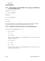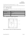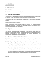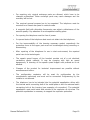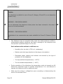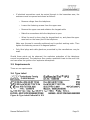
1
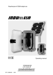
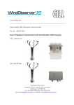
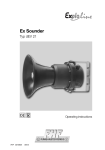
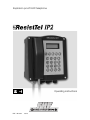
Explosion proof VoIP-telephone
Operating instructions
FHF BA 9711
03/13
BA 9711 03/13
ExResistTel IP2 – Operating instructions
Brand names are used with no guarantee that they may be freely employed. Almost
all hardware and software designations in this manual are registered trademarks or
should be treated as such.
All rights reserved. No part of this manual may be reproduced in any way (print,
photocopy, microfilm or by any other means) or processed, duplicated or distributed
using electronic systems without explicit approval.
Texts and illustrations have been compiled and software created with the utmost
care, however errors cannot be completely ruled out. This documentation is
therefore supplied under exclusion of any liability or warranty of suitability for
specific purposes. FHF reserves the right to improve or modify this documentation
without prior notice.
Note
Please read the operating manual carefully before installing the telephone.
This is only a manual for the explosion proof version. The most important
mounting and installation instructions are part of this document. For the
complete configuration and operating of all features as well as the
description of the special versions the knowledge of the complete manual
is necessary.
The complete manual is attached on the CD.
Please check the contents of the box for completeness.
Copyright © 2013
FHF Funke + Huster Fernsig GmbH
Gewerbeallee 15 – 19
45478 Mülheim an der Ruhr
Tel +49 (208) 8268-0
Fax +49 (208) 8268-377
http://www.fhf.de
Page 2
Manual ExResistTel IP2
Contents
1
1.1
1.2
1.3
1.3.1
1.3.2
1.3.3
1.4
1.4.1
1.4.2
1.4.3
1.4.4
1.4.5
1.4.6
1.4.7
1.4.8
1.4.9
1.4.10
2
2.1
2.1.1
2.1.2
2.1.3
2.1.4
2.1.5
2.1.6
2.1.7
2.1.8
2.1.9
2.2
2.3
3
3.1
3.2
3.3
3.4
3.5
3.6
4
General............................................................................. 5
Operation ......................................................................... 5
Description ....................................................................... 5
Construction..................................................................... 6
Housing ................................................................................. 6
Configuration Plug Connector.................................................. 6
Intrinsically Safe Keypad Connection ....................................... 6
Electrical Characteristic Parameter ................................. 7
Power Supply DC (not intrinsically safe)................................... 7
Power Supply PoE according to IEEE 802.3 af (not intrinsically
safe) ..................................................................................... 7
LAN Interface 10/100 BASE-TX according to IEEE 802.3 (not
intrinsically safe) .................................................................... 8
Potential-free Relay Contacts (not intrinsically safe).................. 8
Cable Shield........................................................................... 9
Configuration Plug Connector................................................ 10
Intrinsically Safe Headset...................................................... 10
Internal and External Earth and Potential Equalisation
Connecting Bolt PA ............................................................... 10
Voltaic Isolation ................................................................... 10
Voltaic Isolation of the Relay Contacts ................................... 11
Commissioning............................................................... 12
Mounting ........................................................................ 12
Cable Screw Caps................................................................. 13
Inside View of Telephone upper Part ..................................... 13
Inside View of Telephone lower Part...................................... 14
Drilling Diagram ................................................................... 14
Connecting Plan ................................................................... 15
Connection Potential Equalisation .......................................... 15
Ethernet Connection ............................................................. 15
External Power Supply Connection ........................................ 16
Relay Connection ................................................................. 16
Setup .............................................................................. 17
Operating Position ......................................................... 17
Information.................................................................... 18
Service............................................................................ 18
Care and Maintenance ................................................... 18
Disposal.......................................................................... 18
Warning and Security Instructions................................ 18
Requirements................................................................. 21
Type Label ...................................................................... 21
Declarations and Approvals ........................................... 22
Manual ExResistTel IP2
Page 3
4.1
4.2
4.3
5
Page 4
EC Type Examination Certificate ExResistTel IP2 ......... 22
IECEx Certificate of Conformity ExResistTel IP2 .......... 25
Declaration of Conformity ExResistTel IP2 ................... 26
Technical Data................................................................ 28
Manual ExResistTel IP2
1 General
The telephone ExResistTel IP2 is an explosion proof version of the weatherproof
telephone ResistTel IP2 / IP152 with all its features. The operating manual is still
valid, with the addition of the following items.
1.1 Operation
The telephone type ExResistTel IP2 will be used as stationary telephone in areas,
which may be put to risk by explosive gas or dust atmosphere and make is necessary
to use devices of the device group II of the device class 2G and 2D. According to
regulations the general purpose of the telephone is hanging vertically on a wall or
hanging vertically on a mounting plate.
1.2 Description
The telephone type ExResistTel IP2 is realized according to the following type of
protection:
•
Type of ignition protection: Ex e [ib] mb IIC T4 Gb
•
Type of ignition protection: Ex tb [ib] IIIC T135°C Db
•
Degree of protection of enclosure: IP66
•
Working environment temperature range: -40 °C ≤ Tu ≤ +60 °C
The telephone type ExResistTel IP2 is designed for connecting to the Ethernet
according to IEEE802.3.
The telephone has to be included into
internal earth connecting bolt of the
connecting bolt at the housing (see
equalisation must exist inside and outside
the potential equalisation either with the
metal plate or with the external earth
examples of connection). The potential
of the explosion at risk area.
The telephone supports the connection of an intrinsically safe headset.
The headset is not part of this telephone. To connect the intrinsically safe headset
the plug mounted on the left side of the housing has to be replaced be an acceptable
explosion protected cable gland.
Manual ExResistTel IP2
Page 5
Note
The installation prescribed in the regulations according to IEC/EN 60079-14 and the
national installation regulations have to be respected.
1.3 Construction
1.3.1
Housing
The telephone type ExResistTel IP2 has a non coloured housing made of an
electrostatic conductive pressed basic material and a stainless steel keypad.
Optionally the housing can be coloured with an electrostatic conductive colour.
In the front plate of the keypad is a display cut-out closed with a viewing glass.
The housing consists of a box-shaped bottom part with a tray for inserting the
electronic and a curved top cover with a keypad.
The top cover will be pressed with four screws to the upper part with in between a
revolving seal and generates the intrinsically safe as well as the non-intrinsically safe
terminal compartment. In the tray is a grouting cup with the embedded electronic.
1.3.2
Configuration Plug Connector
A 6 pin plug connector sticks out of the grouting tray inside the telephone (14).
The configuration plug connector will be used by the manufacturer of the telephone
type ExResistTel IP2 for configuration only and must not be connected.
The programming by the installer is not allowed.
1.3.3
Intrinsically Safe Keypad Connection
An intrinsically safe 14-terminal ribbon cable with a female plug will be carried out of
the grouting tray inside the telephone.
The female plug has to be plugged to the 14 pin plug connector in the upper part of
the housing securely, before the telephone will be screwed down.
Page 6
Manual ExResistTel IP2
1.4 Electrical Characteristic Parameter
1.4.1
Power Supply DC (not intrinsically safe)
Terminal no.: 16, 17
Un = DC 19.2 … 52.8 V
Um = DC 53 V
Isc = 100 A
For this connection cables with a transversal section of 1.5 mm² to 4 mm² are
allowed to be used only.
1.4.2
Power Supply PoE according to IEEE 802.3 af (not
intrinsically safe)
Terminal no.: 11, 12, 14, 15
Un = DC 24 … 48 V
Um = DC 57 V
Isc = 100 A
For the LAN connection it is only allowed to use cables of the type CAT5e or higher.
To observe the EMC rules with netting shielded cables have to be used.
Note
Using a power supply via PoE it is only allowed to use the unused data cable pairs
of a 10/100 Mbit/s Ethernet cable for the power.
Manual ExResistTel IP2
Page 7
1.4.3
LAN Interface 10/100 BASE-TX according to IEEE 802.3
(not intrinsically safe)
Terminal no.: 8, 9, 10, 13
Un = ±2.5 V (10 BASE-TX)
respectively
Un = ±1 V (100 BASE-TX)
Um = ±7 V
Um = DC 57 V
For the LAN connection it is only allowed to use cables of the type CAT5e or higher.
To observe the EMC rules with netting shielded cables have to be used.
1.4.4
Potential-free Relay Contacts (not intrinsically safe)
Terminal no.: 18, 20 respectively no.: 21, 23
•
Umax = AC 250 V
Imax = 5 A
Pmax = 100 VA
For this connection cables with a transversal section of 1.5 mm² to 4 mm² are
allowed to be used only.
•
Umax = DC 230 V
Imax = 0.5 A
Pmax = 100 W
For this connection cables with a transversal section of 0.75 mm² to 4 mm²
are allowed to be used only.
Page 8
Manual ExResistTel IP2
Umax = DC 50 V
•
Imax = 1 A
For this connection cables with a transversal section of 0.75 mm² to 4 mm²
are allowed to be used only.
Umax = DC 30 V
•
Imax = 5 A
Pmax = 100 W
For this connection cables with a transversal section of 1.5 mm² to 4 mm² are
allowed to be used only.
The terminals no. 19 and 22 according to the connection plan are not used and must
not be connected.
1.4.5
Cable Shield
The cable shield of the LAN cable respectively the earth lead of the DC power cable
have to be connected to the terminals no. 6 respectively no. 7. The cable shield of
the LAN cable must be isolated according to the respective installation regulations.
The standard IEC/EN 60079-14 must be respected.
The conductive shield of the network cable has to be handled in the following way:
•
The cable coating of the network cable has to be striped.
•
The single conductor and the cable screen have to be separated.
•
The cable screen has to be drilled to a common conductor. When indicated
existing screen foils and auxiliary wires have to be removed.
•
Suitable isolating tube has to be pushed over the drilled cable screen. The
total length should not be longer than necessary for a secure arrangement of
the wiring.
•
The bare end of the drilled cable shield may be connected directly (The
terminals are approved for connecting flexible wires) or otherwise connected
with a mounted end sleeve for strands.
•
Advantageously these cable works should be done before inserting the cable
into the housing.
Manual ExResistTel IP2
Page 9
The preinstalled cable connection between terminal no. 5 and internal earth
connecting bolt of the metal plate is security relevant and must not be interrupted.
Caution
The air and the creepage distance at the terminals must not be reduced by the kind
of connection of the wires at these connection terminals.
1.4.6
Configuration Plug Connector
The 6 pin configuration plug connector must not be connected.
1.4.7
Intrinsically Safe Headset
Terminal no.: 1, 2, 3, 4
Uo = 16.4 V
Io = 220 mA
Po = 450 mW
Co = 424 nF
Lo/Ro = 78 µH/Ω
The headset type MT53H79B-56 according NEMKO 02ATEX059X respects the
necessary connection requirements and can be used. The connection with other
headsets must be checked according the respective installation rules. The standard
IEC/EN 60079-25 must be respected.
1.4.8
Internal and External Earth and Potential Equalisation
Connecting Bolt PA
For this connection cables with a transversal section of 4 mm² to 6 mm² can be
used.
1.4.9
Voltaic Isolation
The supply DC, the supply PoE, the LAN interface and the intrinsically safe headset
are safety voltaic separated up a voltage of 250 Veff.
Page 10
Manual ExResistTel IP2
1.4.10 Voltaic Isolation of the Relay Contacts
The two potential free relay contacts are safety voltaic separated against each other
up to a voltage of 440 Veff.
Manual ExResistTel IP2
Page 11
2 Commissioning
For operation and commissioning, the application of standard IEEE 802.3 is
compulsory.
The ExResistTel IP2 telephone must be connected to a LAN (Local Area Network)
connection. The telephone can be powered with PoE (Power over Ethernet). In this
case the power supply must use the free cable pairs. Using the phantom power
supply is not possible and not allowed.
Alternatively the telephone connected with an external DC power supply (19.2 V –
52.8 V, 12.95 W).
2.1 Mounting
The telephone must be installed on a plane surface in vertical operating position
only. Loosen the cover screws and detach the upper part of the telephone (1). If the
optional accessory headset is being employed, attach the bracket using two screws
to the rear panel of the lower part of the telephone. (With the accessories named
before, the bracket and screws are in the scope of delivery. With all accessories a
cable gland is delivered.) Put four screws, having a head diameter of 10 to 13 mm
into the holes (20) and attach the lower part of the telephone (3) to the wall or to a
holder.
Guide the telephone wire through the cable screw cap (4) and place it on the
terminals. Only wires having a sheath diameter of 5.5 to 13 mm should be used
because otherwise the IP66 housing protection standard is not guaranteed.
Prior to assembly, check cover seal for tightness. Using the plug connector (7), plug
the ribbon cable onto the pin contact strip (8) in the upper part of the housing.
Attach the upper part of the telephone and fasten it to the lower part of the
telephone with the four cover screws (2). Upon disassembly of optional accessories,
suited sealing plugs must be used to close the resulting openings.
In this telephone connected cords may have hazardous voltages.
To ensure that no water gets into the enclosure it is essential that no gaskets are
damaged during installation. The ingress of water can cause accessible parts of the
telephone to become live.
For mounting of the cable screw caps only dedicated toys are allowed.
The cable screw caps are useful for fixed mounted cables only.
Page 12
Manual ExResistTel IP2
The locking torque of the upper part screws is 1.2 …1.5 Nm.
Installation and connection must be carried out by competent personnel familiar with
electrical and network installations.
2.1.1
Cable Screw Caps
The preinstalled cable screw caps (4) of the explosion proof telephones have the
following properties:
certificate
operating temperature
thread diameter
type of ignition protection
type of protection
cable diameter
locking torque coupling ring
cable
2.1.2
IECEx PTB 05.0004 X, PTB 99 ATEX 3128 or equivalent
-40 °C to +70 °C
Ø M20 x 1.5
Ex e II
IP66
Ø 5.5 mm to Ø 13 mm
2.5 Nm to 3.5 Nm
Inside View of Telephone upper Part
Figure 1: Inside View of upper Part Telephone ExResistTel IP2
Manual ExResistTel IP2
Page 13
2.1.3
Inside View of Telephone lower Part
Figure 2: Inside View of lower Part Telephone ExResistTel IP2
2.1.4
Drilling Diagram
Figure 3: Drilling Diagram Wall Mounting
Page 14
Manual ExResistTel IP2
The diameter of the drilled hole is dependent on the screw employed (screw
diameter max. 8 mm) and the type of supporting base material (steel, wood,
concrete, plasterboard etc.) and must be chosen accordingly.
2.1.5
Connecting Plan
Figure 4: Terminals of the Explosion Proof VoIP Telephone ExResistTel IP2
2.1.6
Connection Potential Equalisation
The terminals 5 – 7 are available for the potential equalisation. The terminal 5 is
reserved fort he connection of the printed board with the potential equalisation bolt.
2.1.7
Ethernet Connection
At the terminals 8 – 15 the Ethernet cable inclusive PoE can be connected. The
assignment is as follows:
terminal
description
8
Rx –
9
Rx +
10
Tx –
11
PoE1
12
PoE1
13
Tx +
14
PoE2
15
PoE2
Table 1: Ethernet Connection of the ExResistTel IP2
PoE will be supported with the unused pairs of data lines of a 10/100 Mbit/s Ethernet
connection only. The polarity will be recognised by the phone automatically.
Manual ExResistTel IP2
Page 15
If the Ethernet interface of the VoIP telephone is configured to the auto or auto-mdi
mode, the Rx and Tx pairs can be exchanged, because the telephone recognizes in
these cases receive and transmit automatically.
2.1.8
External Power Supply Connection
An external power supply can be connected to the terminals 16 (+) and 17 (-). The
external voltage DC 24 … 48 V will be necessary.
If an external power supply is in use, the LAN connection must not be connected to
PoE.
2.1.9
Relay Connection
The telephone has two relays with each a single switch at its proposal.
18 / 21
20 / 23
Figure 5: Terminal Assignment Relays of the Explosion proof VoIP
Telephone ExResistTel IP2 (Exposition: Relay not active)
terminal
description
18 (relay 1)
base contact relay 1
19 (relay 1)
not used
20 (relay 1)
switching contact relay 1
21 (relay 2)
base contact relay 2
22 (relay 2)
not used
23 (relay 2)
switching contact relay 2
Table 2: Terminals of the Relays of the Explosion proof VoIP Telephone
ExResistTel IP2
The terminals of the relays are below a cover to be protected against random
Page 16
Manual ExResistTel IP2
touching. The terminals must be protected again carefully with the cover after
connecting.
2.2 Setup
The configuration of the ExResistTel IP2 follows as described in the operating manual
of the normal ResistTel IP2 / IP152. The manual can be found on the CD attached to
the telephone.
2.3 Operating Position
The telephone may be mounted hanging vertically on a wall or hanging vertically on
a mounting plate.
Manual ExResistTel IP2
Page 17
3 Information
3.1 Service
The telephone contains no serviceable parts.
3.2 Care and Maintenance
The telephone is maintenance-free. Still, if the operating area is highly contaminated
by dust, fat, oil etc., the telephone should be cleaned from time to time.
The telephone may only be cleaned using a damp cloth in order to avoid electrostatic
charging.
Never use sharp objects for cleaning.
During maintenance, check accessible seals for function, e.g. regarding possible
damage or positioning. If the seals are damaged, operating the telephone is not
allowed. Damaged seals must be replaced.
3.3 Disposal
The complete telephone should be disposed of as electronic waste. When the
telephone is disassembled, plastics, metals and electronics components are to be
disposed of separately. In every single case the national requirements and
regulations for waste disposal must be observed.
3.4 Warning and Security Instructions
This telephone is an explosion proof and weatherproof telephone especially for use in
a harsh industrial environment.
The following warning and security instructions must be respected:
•
The telephone is build up in protection class I and must be connected and
used with the required voltages only. The connection cable has to be mounted
without risk of stumbling.
•
Is must be paid attention that the telephone, the connection cable, etc. must
not be damaged. In a damaged state the use of the telephone is not allowed.
•
For using the telephone the laws and the industrial regulations, the accident
prevention, respectively the electrical regulations must be respected.
Page 18
Manual ExResistTel IP2
•
For repairing only original exchange parts are allowed, which have to be
changed professional. Other exchange parts may cause damages and the
warranty will be lost.
•
The required general purpose has to be respected. The telephone must be
mounted on a closed rear panel in vertical mode.
•
A magnetic field with disturbing frequencies can adjust a disturbance of the
acoustic quality. Pay attention to an acceptable installing place.
•
For opening the telephone must be free of power.
•
In opened state of the telephone dust must not attain into the telephone.
•
For the impermeability of the housing necessary gasket respectively the
protective cover at the upper part must not be damaged during mounting or
dismounting.
•
After repairing of the telephone for use in dust environment, the repaired
parts have to be tested again.
•
The speech speed hopper of the handset consists out of a not electrical
conductive plastic material. It may be charging with high air speed
dangerously. A cleaning of the speech speed hopper with pressed air is not
allowed.
•
Changes of the product for technical improvement are possible without
announcement before.
•
The configuration conductor will be used for configuration by the
manufacturer exclusively and must not be connected. Programming by the
installer is not allowed.
•
The telephone has to be included into the potential equalisation either with
the internal earth connecting bolt of the metal plate or with the external earth
connecting bolt at the housing (see examples of connection). The potential
equalisation must exist inside and outside of the explosion at risk area. The
potential equalisation is necessary to support the explosion protection.
Manual ExResistTel IP2
Page 19
Caution
The telephone is suitable for use in Group II, Category 2G and 2D or non-hazardous
locations only.
WARNING – EXPLOSION HAZARD
Do not disconnect the telephone unless power has been removed or the area is
known to be non-hazardous.
WARNING – EXPLOSION HAZARD
Substitution of any components may impair suitability for Group II, Category 2G and
2D.
•
The telephone may be operated solely under the stated ambient conditions.
Unfavourable ambient conditions can lead to damage of the telephone and
thus present a potential danger for the user.
Such unfavourable ambient conditions are:
o Humidity of air too high (>75% rel., condensing)
o Moisture and dust (pay attention to the degree of protection)
o Flammable gases, vapours and solvents not covered by the type of
protection for the telephone.
o Too high ambient temperatures (> +60°C).
o Too low ambient temperatures (< -40°C).
•
During operation of the telephone the temperature must not exceed nor fall
below the prescribed range of ambient temperatures. It is not allowed to
operate the telephone with an additional cover.
•
Make sure the wiring is voltage-free upon connecting or disconnecting the
wires in the terminal room.
Page 20
Manual ExResistTel IP2
•
If electrical connections must be carried through in the hazardous area, the
enclosure must be opened and closed as follows:
o Remove voltage from the telephone.
o Loosen the fastening screws from the upper case.
o Remove the upper case and unfasten the keypad cable.
o Make the connections while the telephone is open.
o When the work is done, plug the keypad back on, and place the upper
case back on the lower part of the telephone.
Make sure the seal is correctly positioned and in perfect working order. Then
tighten the fastening screws in a diagonal pattern.
•
Only blind plugs and cable glands as prescribed by the manufacturer may be
used.
Should these points not be observed, the explosion protection of the telephone
cannot be guaranteed. The telephone then poses a potential threat to the user’s life
and can cause the ignition of an explosive atmosphere.
3.5 Requirements
There are no requirements.
3.6 Type Label
Figure 6: Type Label ExResistTel IP2
Manual ExResistTel IP2
Page 21
4 Declarations and Approvals
4.1 EC Type Examination Certificate ExResistTel IP2
Page 22
Manual ExResistTel IP2
Manual ExResistTel IP2
Page 23
Page 24
Manual ExResistTel IP2
4.2 IECEx Certificate of Conformity ExResistTel IP2
The IECEx certificate of conformity can be seen in the internet at the link:
http://iecex.iec.ch/iecex/iecexweb.nsf/421ce8815c53a3afc1257a1e00576486/a1c67f45a48322ebc1257b18004520b2?OpenDocument
Manual ExResistTel IP2
Page 25
4.3 Declaration of Conformity ExResistTel IP2
Page 26
Manual ExResistTel IP2
Manual ExResistTel IP2
Page 27
5 Technical Data
Connection data
Power supply
Voltage PoE
PoE
Voltage external power supply
Power requirement
Power over Ethernet refer to IEEE
802.3af or external power supply
48V DC (Min. 44V, Max. 57V). The power
has to be transmitted at 10/100 Mbit/s
Ethernet connections only with the
unused pairs of data lines.
Class 0
19.2 V – 52.8 V DC
12.95 W
Switching power of the relays
250 V, 5 A, 100 VA AC
230 V, 0.5 A, 100 W DC
50 V, 1 A, DC
30 V, 5 A, 100 W DC
Connection Ethernet
Terminals (10/100 Mbit/s)
Ringing volume
Max. 95 dB(A) in 1 m distance
Housing
Material
(Height x Width x Depth) without cable
screw caps and without earth bolt
Weight
Display
Keypad
Hook switch
Operation general purpose
Handset
Mouthpiece
Receiver inset
Sling holder
Handset cable
Page 28
Glass-fibre reinforced polyester
267 x 225 x 132 mm
ca. 6.0 kg
• 182 x 64 pixel
• Field of view ca. 78 mm x 26 mm
• Metal keypad with ice protection
• 21 keys with ABC marking
Reed contact without mechanical switch
Vertical wall mounting. The telephone
must be mounted on a closed rear panel.
Electret-foil microphone
Dynamic receiver inset with magnetic
field generator
Integrated adjustable sling holder
Armed court
Manual ExResistTel IP2
Environment conditions
Operation environment
Transport and storage temperature
Air humidity
Conformities
Degree of protection of enclosure
Degree of protection against external
mechanical impacts
Declaration of Conformity
Restriction of Hazardous Substances
(RoHS)
Waste Electrical and Electronic
Equipment (WEEE)
EC Type Examination Certificate
Marking
IECEx Certificate of Conformity
Marking
Employed standards (extracts)
User interface
Web-interface (administration)
Telephone (user menu)
Manual ExResistTel IP2
-40°C…+60°C
-40°C…+80°C according to EN/IEC60721
75 %
IP66 according to EN/IEC 60529
IK09 according to EN/IEC 62262
Directive
Directive
Directive
Directive
Directive
1999/5/EG (R&TTE)
2004/108/EG (EMC)
2006/95/EG (low voltage)
94/9/EC (ATEX)
2011/65/EG
Directive 2012/19/EG
EAR registration no.: DE 58023377
PTB 12 ATEX 2025
II 2 G Ex e [ib] mb IIC T4 Gb
II 2 D Ex tb [ib] IIIC T135°C Db
IECEx PTB 13.0007
Ex e [ib] mb IIC T4 Gb
Ex tb [ib] IIIC T135°C Db
• IEC/EN 60079-0
• IEC/EN 60079-7
• IEC/EN 60079-11
• IEC/EN 60079-14
• IEC/EN 60079-18
• IEC/EN 60079-31
• IEC/EN 60529
• IEC/EN 60721
• IEC/EN 60950-1
• IEC/EN 60950-22
• IEC/EN 61000-6
• IEC/EN 62262
English
16 languages adjustable
Page 29
Subject to alterations
or errors
FHF Funke + Huster Fernsig GmbH
Gewerbeallee 15-19 · D-45478 Mülheim an der Ruhr
Phone +49 / 208 / 82 68-0 · Fax +49 / 208 / 82 68-286
http://www.fhf.de · e-mail: [email protected]