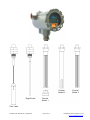
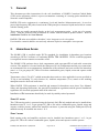
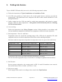
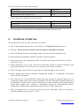
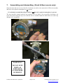
1
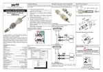
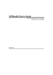
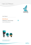
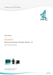
Safety Instructions IECEx Centurion Guided Radar HAWK CGR SERIES IECEx Zone 0/1, Zone 1 Intrinsically Safe probe / Flameproof enclosure IECEx TSA 14.0037X Ex d [ia] ia IIC T6 Gb Ga Tamb = -40C to +60C IP 66, NEMA 4X (T6 … T1) Equipment types: CGR2 2 wire Centurion Guided Radar CGR4 4 wire Centurion Guided Radar Document No. 3548 Version 1.4 5 December 2014 50 Safety Instr IECEx Zone0-1 (CGR).docx Page 1 of 16 Hawk Measurement Systems Pty Ltd http://www.hawkmeasure.com NOTES: 50 Safety Instr IECEx Zone0-1 (CGR).docx Page 2 of 16 Hawk Measurement Systems Pty Ltd http://www.hawkmeasure.com Contents Centurion Guided Radar .................................................................................................... 1 1. General....................................................................................................................... 5 2. Hazardous Areas ........................................................................................................ 5 3. Equipment Identification ............................................................................................. 6 4. Dual Compartment Enclosure .................................................................................... 7 5. Putting Into Service .................................................................................................... 8 6. Conditions of Safe Use ............................................................................................... 9 7. Assembling and dismantling (Front & Rear covers only) ......................................... 10 8. Installation and Wiring .............................................................................................. 12 9. Adjustment ............................................................................................................... 12 10. Application Conditions .............................................................................................. 13 11. List of IECEx certified equipment types .................................................................... 14 12. Wiring configuration drawings ................................................................................... 14 13. Approval Standards .................................................................................................. 14 14. IECEx Certificate of Conformity ................................................................................ 14 15. Manufacturer Contact Information ............................................................................. 15 50 Safety Instr IECEx Zone0-1 (CGR).docx Page 3 of 16 Hawk Measurement Systems Pty Ltd http://www.hawkmeasure.com Coaxial Model 2 Rigid Probe Coaxial Model 3 Coaxial Model 1 Flexi cable 50 Safety Instr IECEx Zone0-1 (CGR).docx Page 4 of 16 Hawk Measurement Systems Pty Ltd http://www.hawkmeasure.com 1. General This document provides instructions for the safe installation of HAWK Centurion Guided Radar (CGR) series equipment, which is a process transmitter consisting of a sensing probe attached to an electronic control amplifier. HAWK CGR series equipment is a continuous Level and Interface Measurement unit. It uses low power high frequency RF pulses based on the TDR principle to measure liquids and solids in contact with the sensing probe. These units are usually mounted directly at the level measurement point – at the top of a storage vessel – with the probe directed downwards in contact with the material product surface. Refer to Installation Guide in the User Manual. HAWK CGR units are available with either 2 wire loop power or 4 wire option. User interface controls shall be accessed only when an explosive atmosphere is not present. 2. Hazardous Areas The HAWK CGR is certified under IECEx standards for installation in hazardous gas locations according to IECEx Certificate of Conformity IECEx TSA 14.0037A. IECEx certified equipment is recognised in most countries around the world. The HAWK CGR enclosure has a dual compartment with segregated Ex d and cable connection sections. The amplifier is located inside the flameproof (Ex d) compartment and the user connections are terminated in the rear compartment. Installation of the enclosure has been certified for hazardous zone 1 or 2, in gas groups IIC, IIB or IIA where combustible gases, liquids, mists and vapours could be present. Temperature class is T6 (85C) which means that these units are also applicable in areas specified as T5 up to and including T1 (refer Section 5e). Ambient temperature (Tamb) stated on the marking nameplate must be observed at all times. When HAWK CGR equipment is installed and mounted in hazardous areas, these User Manual, Safety and Operating Instructions, the general Ex installation regulations and the general installation regulations for electrical equipment must all be observed. Installation of Ex instruments should only be made by suitably trained personnel. Zone 0/1 areas The CGR sensing probe is protected using the Intrinsic Safe (Ex ia) method and can be installed into hazardous zones 0, 1 or 2, in gas groups IIC, IIB or IIA where combustible gases, liquids, mists and vapours could be present, whereas the amplifier enclosure is protected using the Flameproof (Ex d) method can only be installed into zones 1 or 2. Zone 1 areas Both sensing probe and amplifier enclosure can be installed into hazardous zones 1 or 2, in gas groups IIC, IIB or IIA where combustible gases, liquids, mists and vapours could be present. 50 Safety Instr IECEx Zone0-1 (CGR).docx Page 5 of 16 Hawk Measurement Systems Pty Ltd http://www.hawkmeasure.com 3. Equipment Identification An image of the IECEx marking nameplate is shown below. (1) (2) (3) (4) (5) (6) (13) (7) (8) (9) (10) (14) (11) (15) (16) (12) (17) (1) (2) (3) (4) (5) (6) (7) (8) (9) (10) (11) (12) (13) (14) (15) (16) (17) (18) (18) Product Name Part Number Serial Number Manufacture Date Input supply voltage range Maximum value of Um applied to non intrinsically safe circuits Output current and communications protocol Ingress Protection rating Hazardous Locations Marking codes Ambient Temperature Range IECEx Certificate of Conformity number Manufacturer Logo and Name CE marking symbol Quick Reference code Warning symbol and reference to written instructions Warning message Manufacturer Web Address Manufacturer country 50 Safety Instr IECEx Zone0-1 (CGR).docx Page 6 of 16 Hawk Measurement Systems Pty Ltd http://www.hawkmeasure.com 4. Dual Compartment Enclosure Cable Entry User to fit glands Ex d Compartment Cover Locking Screw Rear Compartment Cover Tool Engagement Notches Locking Screw Probe Connection Optional Mounting Pre-fitted and sealed with Certified Ex d Gland (M16X2P) DO NOT ADJUST Earthing Screw 50 Safety Instr IECEx Zone0-1 (CGR).docx Marking Nameplate Page 7 of 16 Hawk Measurement Systems Pty Ltd http://www.hawkmeasure.com 5. Putting Into Service To put a HAWK CGR unit safely into service, the following steps must be taken: a) Follow the instructions in Typical Installations and Installation Guide. b) All CGR series models are fitted with an Ex d cable gland between enclosure port and the sensing probe. This gland must not be tampered with and it must remain tensioned as it was during manufacture. c) Cables coming into the CGR unit shall be sealed using appropriate cable glands to ensure integrity of the rear cable compartment. Cable glands need to be fitted by the user, following the relevant instructions. d) Correct wiring. Follow the instructions in the Wiring Diagram sections. Wiring should be in accordance with relevant installation standards for hazardous area equipment or other local codes of practice. e) Safe temperature Zone 0/1 and Zone 1 Temperature must not exceed the operating range of the CGR unit. In particular, Ex rated equipment must not exceed the temperature limits shown on the marking nameplate. Maximum ambient temperatures dependent on temperature classes are given in the table below: Temperature Class T6 T5 T4 T3 T2 T1 Sensing Probe Temperature -40°C to +85°C -40°C to +100°C -40°C to +135°C -40°C to +200°C -40°C to +300°C -40°C to +450°C Enclosure Temperature -40°C to +76°C -40°C to +76°C -40°C to +76°C -40°C to +76°C -40°C to +76°C -40°C to +76°C Temperatures above those specified in this table should not be exceeded. The user must take appropriate steps to ensure there is no danger of ignition from hot surfaces. f) Safe Pressure. Process pressure subjected to the sensing probe in EPL Ga and Gb hazardous areas must be between the limits of 80 to 110 kPa. (0.8 bar to 1.1 bar) g) Safe power supply. Power supply values must be according to those stated in the Specifications. 50 Safety Instr IECEx Zone0-1 (CGR).docx Page 8 of 16 Hawk Measurement Systems Pty Ltd http://www.hawkmeasure.com h) Probe Tensile Force (Flexi cable models) Probe Type Stainless steel rope, 4 mm @ 20C Stainless steel rope, 8 mm @ 20C Tensile Force 5 kN 19 kN i) Probe Lateral Force (Rigid and Coaxial models) Probe Type Rod, 8 mm Coax, 25 mm Lateral Force 2 kN 4 kN j) Do not put into service where there is a possibility of contact with acetic acid. 6. Conditions of Safe Use The instructions for safe use of the CGR unit is as follows: a) The CGR equipment must put into service safely. (see Putting Into Service, above). b) Warning: Do not open the enclosure when an explosive atmosphere is present. c) The User Manual must be read and understood by any person involved with this unit. d) Environment and installation conditions should be checked regularly. e) Process pressure at the sensing probe in EPL Ga and Gb areas must be between 80 to 110 kPa. (0.8 bar to 1.1 bar) f) When opening the cover of any CGR unit, prevent dust, liquids or chemical substances from getting inside the unit. Do not leave any cover open in rain or snow conditions. g) The LCD display on the CGR series transmitter is visible through the clear window. h) Before making any wiring or hardware configuration changes, it is important to disconnect power from the equipment. i) The enclosure has a non-conducting coating and may generate an ignition-capable level of electrostatic charge under certain extreme conditions. The user shall ensure that the equipment is not installed in a location where it may be subjected to external conditions (such as high-pressure steam) which might cause a build-up of electrostatic charges on non-conducting surfaces. Additionally, cleaning of the equipment should be done only with a damp cloth. j) When incorporated into an electrical system, the service temperature range the enclosure is exposed to shall not exceed -40°C to +76°C. 50 Safety Instr IECEx Zone0-1 (CGR).docx Page 9 of 16 Hawk Measurement Systems Pty Ltd http://www.hawkmeasure.com 7. Assembling and dismantling (Front & Rear covers only) Only the front and rear covers of the Ex d enclosure are able to be removed in CGR series models, and only if an explosive atmosphere is not present. It is absolutely essential that this procedure is not done if an explosive atmosphere is present. The user interface controls and the rear terminal cover are able to be accessed by loosening a set screw then unscrewing the top cover with the aid of a suitable hand tool which does not cause any damage to the equipment. WARNING ! DO NOT OPEN WHEN AN EXPLOSIVE ATMOSPHERE IS PRESENT 50 Safety Instr IECEx Zone0-1 (CGR).docx Page 10 of 16 Hawk Measurement Systems Pty Ltd http://www.hawkmeasure.com Warning! Any attempt to alter the enclosure rotational position will void the warranty of the unit. The Sensing Probe is factory fitted to the enclosure and must not be adjusted or tampered with. The Ex d gland which couples the sensing probe to the flameproof enclosure provides a critical sealing function for the enclosure. The internal wires which pass through this gland and the high integrity seal could be damaged if subjected to additional strain or twisting, and therefore this gland must not be disturbed. Ex d Enclosure WARNING ! DO NOT ADJUST OR TAMPER WITH THIS GLAND Process fitting & Sensing Probe 50 Safety Instr IECEx Zone0-1 (CGR).docx Page 11 of 16 Hawk Measurement Systems Pty Ltd http://www.hawkmeasure.com 8. Installation and Wiring Carefully follow Typical Installations, Installation Guide and Wiring Diagram sections. Follow all points listed in Putting Into Service, above. Wiring should be in accordance with relevant installation standards for hazardous area equipment (eg, IEC 60079-14) and any other local codes of practice. Some models have 4 terminals plus Gnd. 9. Adjustment a) Software Adjustment: For software adjustment of CGR unit parameter adjustment and data entry, refer to instructions in Entering Data, and all of the Setup sections. If GosHawk II software is to be used for parameter adjustment and data entering from a lap-top computer, etc, the user must first read and fully understand the information in the GosHawk II Manual either supplied with the equipment or downloaded free from the HAWK web-site: http://www.hawkmeasure.com Basic parameter adjustments to CGR units with HART communications option can be remotely adjusted using a standard HART calibrator. Note: Computing equipment and mobile phones should not be used in a hazardous area. b) Hardware Adjustment: The CGR unit has no hardware adjustments. Note that the sensing probe details and dimensions are included in the model number (engraved into the marking nameplate) and therefore the equipment must not be altered or modified in any way. 50 Safety Instr IECEx Zone0-1 (CGR).docx Page 12 of 16 Hawk Measurement Systems Pty Ltd http://www.hawkmeasure.com 10. Application Conditions a) Voltage Supply: Must be according to the voltage supplies given in Specifications. U = 14 .. 28 V DC Peak voltage that can be applied to the equipment without invalidating the type of protection. Um = 250 V AC Maximum voltage that can be applied to the non intrinsically safe connection of associated equipment without invalidating the type of protection. b) Temperature: Temperature must not exceed the operating temperature range stated in Putting Into Service, above. c) Cable Connection: Cables and wiring must be installed according to the appropriate standards. Cable connection compartment must be sealed using appropriate glands and blanking plugs. If extending the cable, it must be protected in a junction box and terminated in an enclosure suitable for the environment. Refer to Wiring Diagrams. d) Earthing: HAWK CGR equipment should be earthed via a resistance of less than 1 MegOhm to the Earthing Screw to reduce the possibility of electrostatic discharge. e) Electrostatic Discharge: Warning: Avoid Electrostatic Discharge Do not rub the non-metallic surface of this equipment with a dry cloth. Do not install this equipment in areas where nonconductive materials could flow onto the enclosure surface. f) Industrial Conditions: This equipment is designed for use in normal industrial conditions relating to humidity, vibration, etc. If the user intends to operate the equipment in more severe environmental conditions, the manufacturer or local distributor should be consulted for advice. 50 Safety Instr IECEx Zone0-1 (CGR).docx Page 13 of 16 Hawk Measurement Systems Pty Ltd http://www.hawkmeasure.com 11. List of IECEx certified equipment types – CGR2 series – CGR4 series 2 wire Centurion Guided Radar 4 wire Centurion Guided Radar Probe, Flange and Accessory selection in any combination. 12. Wiring configuration drawings Refer to Wiring Diagrams Note: All equipment in Hazardous Areas must have appropriate certification. 13. Approval Standards IEC 60079-0:2011, Sixth edition IEC 60079-1:2007, Sixth edition IEC 60079-11:2011, Sixth edition Explosive Atmospheres – Equipment - General Requirements. Equipment protection by flameproof enclosures ‘d’ Equipment protection by intrinsic safety ‘i’ These standards specify test requirements at standard temperature, pressure and oxygen content. Additional consideration and/or testing may be required for equipment operating outside these limits. 14. IECEx Certificate of Conformity IECEx Certificate of Conformity IECEx TSA 14.0037X can be accessed directly on line using the following hyperlink … http://iecex.iec.ch/iecex/iecexweb.nsf/certificatesAjax/IECEx%20TSA%2014.0037X%20issue%20N o.%200?opendocument or go to http://www.iecex.com/ select ‘View Certificates & Licenses’ then click the ‘Certified Equipment’ box then enter IECEx TSA 14.0037X and click the ‘View certificate’ box to begin the search. 50 Safety Instr IECEx Zone0-1 (CGR).docx Page 14 of 16 Hawk Measurement Systems Pty Ltd http://www.hawkmeasure.com 15. Manufacturer Contact Information Hawk Measurement Systems Head Office 15-17 Maurice Court, Nunawading, Melbourne VIC 3131, Australia PO Box 286, Nunawading, Melbourne VIC 3131, Australia Ph: +61 (0)3 9873 4750 Fax: + 61 (0)3 9873 4538 Email: [email protected] Support: [email protected] Web: http://www.hawkmeasure.com Hawk Measurement Corporate and Sales Office 96 Glenn Street Lawrence, MA 01843, USA Ph: +1 978 304 3000 / +1 888 429 5538 Fax: +1 978 304 1462 Email: [email protected] Web: http://www.hawkmeasure.com 50 Safety Instr IECEx Zone0-1 (CGR).docx Page 15 of 16 Hawk Measurement Systems Pty Ltd http://www.hawkmeasure.com 50 Safety Instr IECEx Zone0-1 (CGR).docx Page 16 of 16 Hawk Measurement Systems Pty Ltd http://www.hawkmeasure.com