1
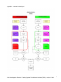
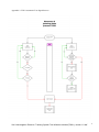
Homologation Directive for Tracking System for
Two-Wheeled vehicles
VERSION 1.0 def (1 October 2012)
- Tracking system requirements and testing methods
(TW01)
Published by the Vehicle Crime Insurance Bureau (VbV)
Effective date: 1 November 2012
CONTENTS
1.
ADMINISTRATIVE PROVISIONS .................................................................................. 3
2.
TECHNICAL DEFINITIONS ........................................................................................... 4
3.
CLASSIFICATION SYSTEM .......................................................................................... 5
4.
TWO-WHEELED TRACKING SYSTEM REQUIREMENTS............................................ 5
5
DESCRIPTION OF THE TESTS .................................................................................... 2
VbV Homologation Directive Tracking System Two-Wheeled vehicles(TW01), version 1.0 def
2
1
ADMINISTRATIVE PROVISIONS
The administrative provisions applying to this inspection specification are as described in
VbV “Administrative Provisions AB04”, version 1.1.
1.1
Items required for a product inspection
Before a product inspection can be considered, the testing institute must be provided with the
following documents through the Certification Body. Where applicable to the product this means:
1.1.1
A completed and signed application form for the performance of the tests.
1.1.2
Documentation showing all the capabilities of the product.
1.1.3
Installation instructions, written in Dutch, complete with:
o projecting of the system parts
o electrical and wiring diagrams
o tests with checklist
o a list of the approved system parts
1.1.4
User manual, written in Dutch, complete with:
o operating conditions
o operating instructions
o the prevention of unnecessary signalling
o what to do in the event of failure/faults
o a list of the system parts relevant to the user
1.1.5
Full technical product documentation, being:
o printed circuit board layouts of all the components
o electrical circuit diagrams of all the components
o mechanical drawings of all the components
o assembly drawing of all the components
1.1.6
Two complete products, to be supplied as in production. The use of prototypes is not
permitted.
1.1.7
Statements for the following items:
o the tests relevant to this inspection specification that have been carried out on an
identical product. These statements must be accompanied by the full test reports
showing that the statements given are based on fact.
1.1.8
Certificates of bodies showing that tests relevant to this inspection specification have been
carried out.
1.1.9
A description of the composition of the system.
1.1.10 In the case of ex-works systems, the system parts of the vehicle involved in the operation
of the system must be indicated.
Submission of the documentation, such as drawings and commercial documentation, on an
electronic data carrier is permitted.
The Certification Body shall have access to the documents described above at the testing institute
at any time and shall of course treat the information as confidential.
VbV Homologation Directive Tracking System Two-Wheeled vehicles(TW01), version 1.0 def
3
2
2.1
TECHNICAL DEFINITIONS
Technical definitions
Alarm condition: the condition of the system when sabotage, jamming or moving detection has
occurred.
Automatic alarm signal: a signal generated by an (alarm) system as a result of an alarm and
forwarded to a receiving environment by electronic means.
Jamming: the electronic disruption of GSM and/or GPS signals aimed at making an automatic
alarm signal impossible. In a jamming condition it is sometimes still possible to transmit an alarm
signal. The onboard action does not depend on this and must always take place.
OBU: OnBoard Unit (the actual system).
Receiving environment: the infrastructure in which automatic alarm signals are received and
processed.
SOC: Secure Operating Centre, definition as set out in the Dutch Private Security Organisations
and Detective Agencies Act [Wet op de Particuliere Beveiligingsorganisaties en Recherchebureaus]
(“...an organisation, set up and equipped for the professional receipt and processing of alarm
signals on behalf of third parties...”).
Standby condition: is described here as an OBU at rest. GSM and/or GPS modules may be
switched off, ignition OFF, physical and logical input monitoring active. On detecting an active
physical and/or logical input the system must switch on automatically (GSM and/or GPS modules)
and physical and logical functions must be available.
System: as described in 3.1 of this Directive.
Vehicle: the mobile object to which this Directive applies; more specifically, the vehicle
characterised as a motorcycle, 25 km/h moped, 45 km/h moped, quad bike, microcar and scoot
mobile.
Original Equiped (OE): a system that has been installed in the factory or factory environment.
Aftermarket: a system or part of a system that has been installed after the vehicle has been
delivered.
Detection: technical method for detecting a pre-defined alarm condition.
VbV Homologation Directive Tracking System Two-Wheeled vehicles(TW01), version 1.0 def
4
3
CLASSIFICATION SYSTEM
3.1
System for two-wheeled vehicles
Consists of an onboard unit (OBU) and any aerials required. The latter may be placed inside
the OBU or be external.
- a system capable of automatically determining the position of the vehicle and forwarding it
to the receiving environment
- the system must be capable of performing all the functions and have all the properties
listed in Section 4 of this specification
4
TWO-WHEELED TRACKING SYSTEM REQUIREMENTS
Tracking systems in vehicles do not interfere with the vehicle technology, using only the power
supply and the horn, which means that the technical requirements of the OBU are limited.
Tracking systems for tvehicles must meet a number of functional requirements, there being no
description of HOW the function is to be carried out. It is a matter of achieving the desired result.
4.1
General
4.1.1
The requirements laid down in this specification apply to systems used for installation in
category L vehicles of Homologation Directive ECE/TRANS/WP.29//78/Rev.2 and fitted
with a 6-12 Volt battery.
4.1.2
Parts of these vehicles that indirectly or directly form part of the system are regarded as a
system part and must also be submitted for inspection. Parts that have previously been
included in the vehicle type approval do not require additional inspection.
4.1.3
If the system or a system part has been integrated with equipment intended for other
purposes, this equipment must meet the inspection requirements to the extent that it has
an impact on the operation of the system.
4.1.4
If requirements exist under Dutch or European legislation for the system or a system part,
they must also comply with or be homologated in accordance with these requirements.
4.1.5
The system must be designed and installed such that every vehicle equipped with it
continues to comply with the technical specifications (type approval).
4.1.6
The system may not in any way put road safety at risk in an activated or non-activated
condition.
VbV Homologation Directive Tracking System Two-Wheeled vehicles(TW01), version 1.0 def
5
4.2
Design requirements
4.2.1
The casing must be “sprayproof” and meet the requirements of IPX-5 waterproof
specifications.
4.2.2
The use of an external relay to effect the operation of the vehicle’s horn is permitted.
4.2.3
All the system parts must meet the homologation requirements and only be supplied
complete. The type designations and/or brand name under which the approval has been
given must be clearly stated on the most important part(s), not visible from outside, while
parts visible from outside (such as sensors) may not be provided with a recognisable
marking.
4.2.4
A production code must be affixed to the printed circuit board or to the casing of the OBU.
It may also be given in the software.
4.2.5
The system must be supplied with a user manual and specific installation instructions for
the product, which must be accompanied by VbV Installation Directive for two-wheeled
vehicles. They may be provided by digital means.
4.2.6
The OBU must be designed so that it can meet the VbV Installation Directive. For the
latest version of the Installation Directive for two-wheeled vehicles, see the VbV website.
4.2.7
The system’s energy supply must be provided by the vehicle’s start battery.
4.2.8
The system must be provided with cabling that makes it possible to install the system
properly in the vehicle.
4.2.9
National coverage in the Netherlands and roaming facilities must be available on the
(GSM) connections used (with the provider’s declaration is permitted).
4.3
Performance requirements
4.3.1
Components and functionalities connected to or used on the system and not described in
this Directive do not form part of the approval of the product.
4.3.2
The system must transmit an automatic test signal at least once every seven days. The
absence of the test signal must be detected by the receiving environment and be
processed in accordance with the protocol laid down (see Appendix 2). The receipt of the
test signal must be logged in the receiving environment. The test signal in any event
includes OBU identity, date and time and the log period covers at least four weeks (first in
first out).
4.3.3
Disabling the system (for maintenance, for example) is only possible if authorised.
4.3.4
When applying for Homologation, the supplier/provider must show that it is registered with
the Dutch Data Protection Authority [College Bescherming Persoonsgegevens]. This can be
demonstrated by submitting the required registration certificate.
4.3.5
Only the horn present on the vehicle may be used for the acoustic signalling.
4.3.6
The power consumption in the standby condition must be limited to not more than 2 mA.
4.3.7
The system must have such an emergency power supply that it makes detection and
reporting possible independently and separately from the power supply.
VbV Homologation Directive Tracking System Two-Wheeled vehicles(TW01), version 1.0 def
6
4.3.8
The system’s emergency power supply must have sufficient capacity to allow the system
to operate for a minimum of five days “stand-alone” and in standby condition.
(Note: this functionality will be reconsidered after a maximum of one year and adjusted, if so desired.)
4.3.9
The system must finally generate a signal before the actual voltage of the emergency
power supply has fallen below the value at which the system can no longer operate. This
value or these values must be indicated by the supplier, where A = upper value, B = lower
value, C = signal value. This signal must be logged in the receiving environment and be
reported to the owner of the vehicle.
4.3.10 The system must immediately detect and report power supply failure. This signal occurs
independently of the ignition on/off condition; it must be generated within 180 seconds of
detection and be processed in accordance with the protocol laid down (Appendices 1 and
2).
4.3.11 As soon as the vehicle is lifted or otherwise wrongfully moved, an automatic alarm signal
must be generated on the basis of the following:
the vehicle is moving at a speed of > 30 km/h with ignition off, or
the OBU detects an alarm condition (moving with ignition off) that continues after 60
seconds, or
the vehicle is moving over a cumulative distance of > 300 metres with ignition off.
4.3.12 When the ignition of the vehicle is switched off, the position known at that time must be
reported to the receiving environment and be stored.
4.3.13 The system must detect a jamming condition immediately, a control period of at least 30
seconds being required. If the jamming condition has not been discontinued after this
control period, the system must operate the vehicle’s horn. This detection is independent
of the status of the ignition (ignition on/off).
4.3.14 The system must operate the horn not later than 90 seconds after the first jamming
detection has taken place. The horn must be operated at a frequency of 1–3 Hz, but may
also be a continuous signal. The length of this cycle may be 25-30 seconds, with an
interval of 0-15 seconds. After one jamming detection this cycle may be generated a
maximum of three times.
4.3.15 When the system, after a jamming detection, has logged back onto the network, an alarm
signal must be generated within 180 seconds. This alarm signal must be logged in the
receiving environment.
4.3.16 The SOC [Particuliere Alarm Centrale] must be capable of retrieving a current position of the
vehicle at any time after a verified theft signal. This applies in the “ignition on” condition or
in the alarm condition.
4.3.17 Alarm transmission over IP is permitted (2G and 3G)
VbV Homologation Directive Tracking System Two-Wheeled vehicles(TW01), version 1.0 def
7
4.4
Function environment and processes
4.4.1
If the receiving environment is physically located in a SOC, the SOC standards
automatically apply. If the receiving environment is NOT located in a SOC, the
supplier/provider must show:
4.4.2
that the data centre where the receiving environment is located meets the requirements
listed below (declaration is permitted):
a. the receiving environment must be of fully redundant construction;
b. the receiving environment must have an automatic emergency power supply at its
disposal;
c. the receiving environment must be set up according to an authorisation system
for access to automated (customer) data. This system must show that staff are
authorised separately to gain access to (customer) data. This system must also
show how the access to this data proceeds by way of an adequate access
threshold. This may be achieved by means of a password, for example. The
receiving environment must also be protected from physical and logical access
from outside by means of the usual security techniques such as a firewall for
logical access control;
d. to prevent data loss the receiving environment must be equipped with a
daily backup of all the modified electronic data. A RAID 1 construction is permitted
for this purpose;
4.4.3
that continuity for this is provided by means of an agreement concluded with the
supplier/provider;
4.4.4
which SOC provides the service and that continuity for this is provided by means of an
agreement.
THE PROCESS DIAGRAMS RELATING TO ORGANISATION AND COURSE OF PROCESSES ARE
INCLUDED IN THE APPENDICES.
4.5
Installation requirements
The “Installation Directive for Two-Wheeled Vehicles” list the inspection points that the installation
of a tracking system for vehicles must meet.
4.5.1
Each supplier must supply this Directive with the installation instructions of its system.
These may be supplied by digital means.
VbV and Kiwa SCM have published the latest applicable version of the “Installation
Directive for two-Wheeled Vehicles” on their websites.
4.6
4.6.1
Certification
By way of derogation from the VbV regulation “Recognition of Installation Companies for
Security Systems in/on Vehicles and Operating Equipment” [Erkenning
Inbouwbedrijven
beveiligingssystemen in/op Voertuigen en Werkmaterieel] of 24 April 2006, see
“Annex 1 Additional Conditions for Two-Wheeled Vehicles” of 1 August 2012.
VbV Homologation Directive Tracking System Two-Wheeled vehicles(TW01), version 1.0 def
8
5
DESCRIPTION OF THE TESTS
5.1
General
5.1.1
The tests to be carried out will be determined by the Test House and the test results of
other Test Houses may be used. The Test House will determine which test results can
actually be used.
5.1.2
The order of the tests to be carried out will be determined by the Test House.
5.1.3
The system parts will be tested in the form in which they are installed and supplied.
5.1.4
The positioning of the system parts during the tests to be carried out will be determined by
the iTest House and, if possible, according to installation instructions. In the event a
manufacturer has special requirements, it must be shown that the position in which the
tests have taken place is maintained in assembly.
5.1.5
System parts will be tested in accordance with the test descriptions.
5.1.6
For the duration of each test no unnecessary alarms may be caused and the system may
not change status, other than in the usual or intended manner.
5.1.7
At the end of each test the system parts must perform according to the manufacturer’s
specifications and may not have undergone any deformations and/or changes that may
impair the operation of the system parts at that time or after a period of time.
5.1.8
An installation must always be concluded with a full system test, which may be automated
and must be logged.
5.2
Test descriptions
Cold test
Temperature
Acclimatisation time
T = -40 °C ± 2 °C; Voltage U = 9 V ± 0.2 V
t = 4 hours
EU 95/56, 5.2.2.1
T = 85 °C ± 2 °C; Voltage U = 15 V ± 0.2 V;
t = 4 hours
EU 95/56, 5.2.2.2
Heat test
Temperature
Acclimatisation time
HF external radiation (EMC)
High frequency external radiation tests according to
Watertightness:
The system must be “spray watertight”
97/24/EC with latest
amendment 2009/108/EC
IPX5
All the above tests may be carried out by a testing establishment recognised and accredited by
the Certification Body. If other test results are available, their acceptance shall be at the discretion
of the Certification Body. All the tests must be preceded by a functional test. After the
performance
of the above tests the system must continue to meet the functional requirements of this regulation.
VbV Homologation Directive Tracking System Two-Wheeled vehicles(TW01), version 1.0 def
9
Appendix 1: Automatic Alarm Signal
VbV Homologation Directive Tracking System Two-Wheeled vehicles(TW01), version 1.0 def
1
Appendix 2: TW01 Automatic Test Signal Process
VbV Homologation Directive Tracking System Two-Wheeled vehicles(TW01), version 1.0 def
1
Appendix 3 Movement and Jamming Alarm
VbV Homologation Directive Tracking System Two-Wheeled vehicles(TW01), version 1.0 def
1