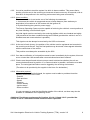
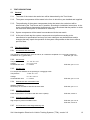
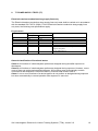
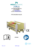
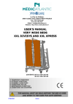
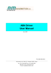
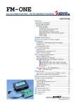
1
Homologation Directive for TT04 Vehicle
Tracking Systems
VERSION 3.0 (31 March 2014)
- Requirements and testing methods for
vehicle tracking systems
Issued by the Insurance Bureau for Vehicle Crime (Stichting VbV)
Effective: 1 April 2014
TABLE OF CONTENTS
1
ADMINISTRATIVE PROVISIONS .................................................................................. 3
2
TECHNICAL DEFINITIONS ........................................................................................... 5
3
CLASS BREAKDOWN OF VEHICLE TRACKING SYSTEMS ........................................ 6
4
VEHICLE TRACKING SYSTEM REQUIREMENTS ....................................................... 7
5
TEST DESCRIPTIONS ................................................................................................ 13
6
TYPE EXAMINATION TEST MATRIX .......................................................................... 15
7
FOLLOW-UP INSPECTION TEST MATRIX ................................................................. 15
8
T7 POWER SUPPLY TESTS (T7) ............................................................................... 16
ANNEX 1: Certification agreement .............................................................................................. 17
VbV Homologation Directive for Vehicle Tracking Systems (TT04), version 3.0
2
1 ADMINISTRATIVE PROVISIONS
The administrative provisions applying to this Homologation Directive are as described in VbV
‘Administrative Provisions AB04’, version 1.1.
1.1 Transition period
This directive shall replace any prior directives. A transition period has been set, lasting until 1
January 2015. Any approvals issued previously shall therefore expire by 1 January 2015 at the
latest. Certificates for products with approvals issued previously will no longer be issued as of 1
January 2015.
1.2 Applicability
The requirements listed in this directive apply to inbuilt vehicle tracking systems (both originalequipped and aftermarket) in vehicles, with the exception of two-wheeled vehicles (see
Homologation Directive TW01).
1.3 Items required for a product inspection
Before a product inspection can be considered, the testing institute must be provided with the
following documents through the Certification Body. Where applicable to the product this means:
1.3.1 A completed and signed application form for the performance of the relevant inspection.
1.3.2 Documentation showing all the capabilities of the product.
1.3.3 A user manual and installation instructions specific to the system provided, written in the
Dutch language as a minimum.
1.3.3.1
The user manual must contain the following:
* Operating conditions
* Operating instructions
* The prevention of unnecessary signalling
* What to do in the event of failure/faults
* A list of the system components relevant to the user
The installation instructions must at least contain the following:
* Projection of the system components
* Electrical and wiring diagrams
* Tests with checklist
* Disruption troubleshooter
* An overview of the system components
If applicable, the installation instructions for original-equipped (OE) systems may be
provided in a language other than Dutch (German or English).
1.3.3.2
1.3.4 Full technical product documentation, i.e.:
o Printed circuit board layouts of all the components
o Electrical circuit diagrams of all the components
o Mechanical drawings of all the components
o Assembly drawing of all the components
1.3.5 Two complete products, to be supplied as in, or being put into, production.
The use of prototypes is not permitted.
VbV Homologation Directive for Vehicle Tracking Systems (TT04), version 3.0
3
1.3.6 Statements for the following items:
o Code for the on/off signal, as well as for mandatory
coded signals such as those of the following components:
- remote controls
- transponder
- numeric keypad
- electronic key
- mechanical key
1.3.7 Declarations stating that:
o the system does not write to the vehicle’s DATA BUS, or
o if a written declaration is received from the official importer or manufacturer
of the vehicle stating that the relevant supplier of the vehicle tracking system may
write to the vehicle’s DATA BUS, that it is permitted for the vehicle tracking system to
write signals to the DATA BUS.
o the system cannot be turned on or off using remote controls that have not been
approved (as described in this inspection specification).
1.3.8 A class description of the composition of the system.
Submission of the documentation, such as drawings and commercial documents,
on an electronic data carrier is permitted.
VbV Homologation Directive for Vehicle Tracking Systems (TT04), version 3.0
4
2
TECHNICAL DEFINITIONS
Original-Equipped (OE): a system that has been installed in the factory or factory environment.
Aftermarket: a system or part of a system that has been installed after the vehicle has been
delivered.
Alarm condition: the condition of the system when sabotage, jamming, alarm or moving detection
has occurred. Communication and position-detection modules must be activated.
Immobilisation: A condition which immobilises the vehicle, preventing it from being able to propel
itself any further once the ignition has been turned off. This condition will never affect the vehicle
while being driven – only its ability to ‘restart’.
DATA BUS: A digital system in a vehicle used to send various messages. The DATA BUS signal
can come in various forms, for example: low-speed CAN-BUS, high-speed CAN-BUS and singlewire CAN.
Detection: Technical method for detecting a pre-defined alarm condition.
Jamming: The electronic disruption of communication and/or position-detection signals, with the
aim of making automatic alarm notification and/or position detection impossible.
Receiving environment: the infrastructure in which automatic alarm signals are received and
processed.
SOC: Secure Operating Centre --- definition as set out in the Dutch Private Security Organisations
and Detective Agencies Act [Wet op de Particuliere Beveiligingsorganisaties en
Recherchebureaus] (‘...an organisation set up and equipped for the professional receipt and
processing of alarm signals on behalf of third parties’).
Vehicle tracking system: The sum of all required components and functions necessary to fulfil the
requirements set in this Homologation Directive.
Standby mode: described here as a vehicle tracking system at rest. Communication and/or
position-detection modules may be switched off, ignition OFF, physical and logical input
monitoring active.
On detecting an active physical and/or logical input, the system must switch on automatically and
communication/position-detection services must be available (alarm condition).
VbV Homologation Directive for Vehicle Tracking Systems (TT04), version 3.0
5
3
CLASS BREAKDOWN OF VEHICLE TRACKING SYSTEMS
Vehicle tracking system with jamming detection
Consisting of a VbV/SCM-approved vehicle tracking system with jamming detection
that automatically activates immobilisation, based on a VbV/SCM-approved
immobiliser (class 1):
- that automatically determines the vehicle’s position and forwards it to the receiving
environment;
- that can perform all the functions and has all the properties as listed in Section 4 of this
specification.
Vehicle tracking system
Consisting of a VbV/SCM-approved vehicle tracking system (without jamming detection)
based on a VbV/SCM-approved immobiliser (class 1):
- that can automatically determine the vehicle’s position and forward it to the receiving
environment;
- that can perform all the functions and has all the properties as listed in Section 4 of this
specification, excluding Sections 4.3 and 5.2.8.
PLEASE NOTE: The category of Vehicle Tracking System (without jamming detection)
will no longer apply as of 1 January 2015. From this date, vehicle tracking systems
without jamming detection will no longer be eligible for inspection, nor will any more
certificates be issued for such systems.
VbV Homologation Directive for Vehicle Tracking Systems (TT04), version 3.0
6
4
4.1
VEHICLE TRACKING SYSTEM REQUIREMENTS
General
4.1.1 Parts of passenger vehicles that indirectly or directly form part of the vehicle tracking
system are regarded as system components and must also be submitted for inspection.
Parts that have previously been included in the vehicle type inspection do not require
additional inspection.
4.1.2 If the system or a component thereof has been integrated with equipment intended for
other purposes, this equipment must meet the inspection requirements to the extent that it
has an impact on the operation of the system.
4.1.3 If requirements exist under Dutch or European legislation for the system or a component
thereof, they must also comply with or be homologated in accordance with these
requirements.
4.1.4 The vehicle tracking system must be designed and installed such that every vehicle
equipped with it continues to comply with the technical specifications (type approval).
4.1.5 The vehicle tracking system may not put road safety at risk in any way.
4.1.6 Components and functionalities that are connected or applied to the vehicle tracking
system but are not described in this homologation directive shall not be included in the
approval of the product.
4.1.7 The vehicle tracking system may only write signals to the vehicle’s DATA BUS if the official
importer or manufacturer of the vehicle has provided a written declaration stating that the
supplier in question may write to the vehicle’s DATA BUS.
Under no other circumstances is it permitted for a system to write to a vehicle’s
DATA BUS.
VbV Homologation Directive for Vehicle Tracking Systems (TT04), version 3.0
7
4.2
Design, performance and functional requirements
4.2.1 All cables (except those for the DATA BUS connection) must be the same colour (this does
not apply to OE systems).
4.2.2 All system components must comply with the homologation requirements, and may only be
supplied as a whole. The type designations and/or brand name under which the approval
has been granted must be clearly stated on the most important components(s) that are not
visible from the outside, while parts visible from the outside (such as sensors) may not be
provided with a recognisable marking.
4.2.3 A production code must be affixed to the printed circuit board or to the casing of the
system, enabling the supplier to determine when and where the system was manufactured.
This may also take the form of software.
4.2.4 It must be possible to position the antennae required for the system in such a way that they
are not visible from outside the vehicle.
4.2.5
The power required by the system must come from the vehicle’s own battery.
4.2.6 Average energy consumption of the vehicle tracking system in standby mode may not
exceed twenty (20.0) mA, measured over a 24-hour period.
Note to Test House: Prior to this test, the system must be able to communicate with the
receiving environment and adequate GPS signals must be present.
4.2.7
4.2.8
The system must have an emergency power supply that enables detection and reporting
independently and separately from the power supply, subject to the following criteria:
4.2.7.1
Test conditions/criteria applicable to the system’s battery capacity – The system must
have its own power supply, with a minimum capacity defined as follows: Using this
power supply, it must be possible to refresh and forward the vehicle’s position to the
operating centre at least once every sixty (60) seconds for a period of at least eight
hours, under normal conditions.
4.2.7.2
The system must finally generate a signal before the actual voltage of the emergency
power supply has fallen below the value at which the system can no longer operate.
This value must be indicated by the supplier.
An alarm signal must be logged by the receiving environment and forwarded or reported by
the SOC to the owner of the vehicle.
VbV Homologation Directive for Vehicle Tracking Systems (TT04), version 3.0
8
4.2.9 It must be possible to track the system live while in alarm condition. This means that a
position must be sent to the receiving environment at least once every 30 seconds, with at
least 90% of the positions in the receiving environment being sent successfully.
4.2.10 Alarm condition:
The alarm condition is met under one of the following circumstances:
1. As soon as the vehicle is transported across a linear distance (from stationary to
destination) of a maximum of 300 meters with the ignition off;
2. By disconnecting the system’s power supply.
The Secure Operating Centre must be capable of retrieving the vehicle’s current position at
any time following a verified theft signal.
An initial signal must be received by the receiving platform within one hundred and eighty
(180) seconds of the alarm condition having been fulfilled (provided the vehicle is not in a
shielded area and communication is possible).
This signal must also always be received by the SOC environment.
4.2.11 At the end of each journey, the position of the vehicle must be registered and recorded in
the receiving environment. Only the final position may be stored, unless agreed otherwise
with the owner/user of the vehicle.
This position must always be accessible by the SOC.
4.2.12 If an alarm notification or final position cannot be sent immediately by the system, this must
occur no later than 180 seconds after communications have been restored.
4.2.13 Checks must be performed at least once per week to determine whether the unit can
communicate and send its position. If no communication is possible, verification must take
place. The test signal/verification must be logged by the receiving environment.
(The above to be provided by the supplier in the form of a declaration.)
4.2.14 Information protocol:
In the event of a verified theft signal, the system must be able to provide at least the
following information to the SOC:
- Position
- Date and time
- Speed
- Direction
- Vehicle identity
- Ignition status
- Alarm condition
It is not necessary to send the identification details of the vehicle, as these may also be
available in a database at the operating centre.
Additional Test House requirement for Sections 4.2.9-4.2.12 and 4.2.15: provided the
vehicle is not in a shielded area and communication is possible.
VbV Homologation Directive for Vehicle Tracking Systems (TT04), version 3.0
9
4.3
Jamming detection requirements
4.3.1 The system must be able to detect jamming on the frequencies it uses to communicate.
For the purposes of testing, the supplier much provide these frequencies to the testing
organisation.
4.3.2 The immobilisation condition may only be altered subject to proper authorisation.
Disconnecting and/or reconnecting the system (or components thereof) may not result in a
change to the immobilisation status.
4.3.3 When jamming is detected, immobilisation must be activated, preventing the vehicle from
being able to transport itself upon being restarted. The following conditions apply:
4.3.3.1
The system must detect jamming immediately, and observe a control period of
between 30 and 60 seconds.
4.3.3.2
If jamming is detected with IGNITION OFF and the jamming continues beyond the
control period, the system must activate immobilisation no later than 10 seconds
after the end of the control period.
detection
0 sec
4.3.3.3
30 sec
immobilisation
40 sec
60 sec
70 sec
If jamming is detected with IGNITION ON, immobilisation must be activated if the
jamming continues longer than 15 minutes, counting from the initial detection.
Immobilisation must be deactivated automatically once no more jamming has been
detected for a period of 10 minutes.
detection
0 min
4.3.3.4
15 min
immobilisation
15 min
release
25 min
If jamming has been detected and remedied according to the above conditions, the
very next communication with the receiving environment must include a jamming
detection report. This information must also be made available to the SOC.
4.3.4 Immobilisation may also be activated by the SOC following a verified report by or on behalf
of the owner/user.
4.3.5 After verification, the Secure Operating Centre must be able to deactivate the
immobilisation (provided the vehicle is not in a shielded area and communication is
possible).
4.3.6 The system must have a deactivation method (emergency procedure) inside the vehicle to
enable the authorised deactivation of immobilisation.
4.3.7 Manual activation/deactivation of immobilisation is permitted.
4.3.8 The driver must be able to see when immobilisation has been activated (only if ignition is
on).
VbV Homologation Directive for Vehicle Tracking Systems (TT04), version 3.0
10
4.3.9 No matter what the circumstances, the immobiliser may only be activated if the ignition has
been off for more than 40 seconds.
4.3.10 The immobiliser may only be deactivated through the use of a numerical random code at
least 4 digits in length (not a default code). Other deactivation methods are permissible,
provided they meet the requirements set in Homologation Directive AA04.
4.3.11 If immobilisation is activated, it must be impossible to alter the immobilisation status by
disrupting the +30 and/or +15 and/or -31.
4.3.12 While being driven, variations of +/- 25 % in the nominal battery voltage may not cause the
system components that effect immobilisation to change status.
4.3.13 If the system includes an immobiliser activated by jamming detection, it must satisfy the
following physical requirements:
- The immobiliser may not be housed in the same casing as the deactivation mechanism
(e.g. dashboard);
- A wired connection must be present between the dashboard and the immobiliser, coded
and with a length of at least 20 cm;
Scenario 1:
Immobiliser separate from
the vehicle tracking system
Dash
board
Immobiliser
≥ 20 cm
coded
VEHICLE
TRACKING
SYSTEM
Dash
board
Scenario 2:
Immobiliser integrated into
the vehicle tracking system
Immobiliser
≥ 20 cm
coded
VEHICLE
TRACKING
SYSTEM
Scenario 3:
Immobiliser controlled
by the vehicle tracking system
via a separate relay
Dash
board
≥ 20 cm
coded
VEHICLE
TRACKING
SYSTEM
Systems with a wireless deactivation method do not need to satisfy these requirements.
VbV Homologation Directive for Vehicle Tracking Systems (TT04), version 3.0
11
4.3.14 The (de)activation of the immobiliser must remain possible at battery voltages between
seven (7) and fifteen (15) volts (for 12-volt nominal systems) or between (18) and thirty
(30) volts (for 24-volt nominal systems).
4.4
4.4.1
4.4.2
Receiving environment/SOC:
If the receiving environment is physically located in an SOC, the SOC standards
automatically apply. If the receiving environment is NOT located in an SOC, the
supplier/provider must demonstrate:
4.4.1.1
that the data centre where the receiving environment is located meets the
requirements listed below (declaration is permitted):
a. The receiving environment must be of fully redundant construction;
b. The receiving environment must have an automatic emergency power supply at
its disposal;
c. The receiving environment must be set up according to an authorisation system
for access to automated (customer) data. This system must show that staff are
authorised separately to gain access to (customer) data. This system must also
show how the access to this data proceeds by way of an adequate access
threshold. This may be achieved by means of a password, for example. The
receiving environment must also be protected from physical and logical access
from outside by means of the usual security techniques, such as a firewall for
logical access control;
d. to prevent data loss the receiving environment must be equipped with a daily
backup of all the modified electronic data. A RAID 1 construction is permitted for
this purpose;
4.4.1.2
that continuity for this is provided by means of an agreement concluded with the
supplier/provider;
4.4.1.3
which SOC provides the service and that continuity for this is provided by means of
an agreement.
All systems must have European coverage (i.e. in all EU member states) in terms of
positioning services and communications. The supplier must provide a declaration to this
effect.
VbV Homologation Directive for Vehicle Tracking Systems (TT04), version 3.0
12
5
TEST DESCRIPTIONS
5.1
General
5.1.1 The order of the tests to be carried out will be determined by the Test House.
5.1.2 The system components will be tested in the form in which they are installed and supplied.
5.1.3 The positioning of the system components during the tests to be carried out will be
determined by the Test House and, if possible, according to installation instructions. In the
event a manufacturer has special requirements, it must be shown that the position in which
the tests have taken place is maintained in assembly.
5.1.4 System components will be tested in accordance with the test matrix.
5.1.5 At the end of each test the system components must perform according to the
manufacturer’s specifications and may not have undergone any deformations and/or
changes that may impair the operation of the system components at that time or after a
period of time.
5.2
Test descriptions
5.2.1 T1 Vibration and shock test:
The frequency must vary from 10 Hz to 500 Hz, at a maximum amplitude of ± 5 mm and a maximum
acceleration of 3 g (peak value).
ECE R97, par. 7.2.8
5.2.2 T2 Cold test
Temperature
Voltage
Acclimatisation time
T = - 40 °C ± 2 °C
U = 9 V ± 0.2 V
t = 4 hours
ECE R97, par. 7.2.2.1
5.2.3 T3 Heat Test
For components installed in the passenger or baggage areas:
Temperature
T = 85 °C ± 2 °C
Voltage
U = 15 V ± 0.2 V
Acclimatisation time
t = 4 hours
5.2.4
T4 Heat test with condensation test
Weather resistance
Seven days in accordance with IEC 68-2-30-1980
5.2.5
ECE R97, par. 7.2.2.2
ECE R97, par. 7.2.4
T5 Power supply test
Power supply tests in accordance with ISO 7637-2 (2004).
ECE R97, Annex 9
5.2.6 T6 External radiation (EMC)
High-frequency external radiation tests
ECE R97, par 7.2.12
ECE R97, Annex 9
5.2.7 T7 Combined functionality/positioning test
Details to follow.
VbV Homologation Directive for Vehicle Tracking Systems (TT04), version 3.0
13
5.2.8 T8 Jamming detection test
Here, the requirements should be tested as described in Section 4.3.
VbV Homologation Directive for Vehicle Tracking Systems (TT04), version 3.0
14
6
TYPE EXAMINATION TEST MATRIX
Component
T1
T2
Test module
T3 T4 T5
T6
T7 T8
HF external radiation
(EMC)
Functionality test
Jamming detection test
Power supply test
Heat test with
condensation test
Heat test
Cold test
Vibration and shock test
X
X
X
Entire system
X
X
X
X
X
7 FOLLOW-UP INSPECTION TEST MATRIX
Component
Test module
T1 T2 T3 T4 T5 T6 T7
X
X
X
X
X
Jamming detection test
X
Functionality test
HF external radiation
(EMC)
Power supply test
Heat test with
condensation test
Heat test
Cold test
Vibration and shock test
Block 1
Block 2
Block 3
Block 4
Block 5
Block 6
Block 7
T8
X
X
X
X
X
X
X
All follow-up inspection tests must be preceded by a functional test and a power supply measurement. After
the performance of the above tests the system must continue to meet the functional requirements of this
regulation (with the exception of the T7 Power supply test).
VbV Homologation Directive for Vehicle Tracking Systems (TT04), version 3.0
15
8
T7 POWER SUPPLY TESTS (T7)
Electrical transient conduction along supply lines only
The Electrical transient conduction along supply lines only tests shall be carried out in accordance
with the standard ISO 7637-2 (2004). For the Electrical transient conduction along supply lines
only tests, the following test specifications apply:
Requirements
Test pulse number
1
2a
2b
3a
3b
4
Immunity test level IV
12V systems
24V systems
-100
-600
+50
+50
+10
+20
-150
-200
+100
+200
-7
-16
5b
+87
+173
Functional status classification
C
B
C
A
A
B (for EUT which must be operational during
engine start phase
C (for other EUT’s)
C
General classification of functional status
Class A: all functions of a device/system perform as designed during and after exposure to
disturbance.
Class B: all functions of a device/system perform as designed during exposure. However, one or
more of them can go beyond specified tolerance. All functions return automatically to within
normal limits after exposure is removed. Memory functions shall remain class A.
Class C: one or more functions of a device/system do not perform as designed during exposure
but return automatically to normal operation after exposure is removed.
VbV Homologation Directive for Vehicle Tracking Systems (TT04), version 3.0
16
ANNEX 1: Certification agreement
Undersigned parties do declare this agreement with the intention to guarantee the quality of security systems
supplied under the approval label in conformity with the requirements as laid down in the Homologation
Directive TT04.
To maintain this the certification institute (NAME CERTIFICATION INSTITUTE) and the supplier / approval
holder lay down the following arrangements:
Both parties shall adhere to what is stated in this Directive TT04 with reference to the Directive AB04, in
specific the Administrative requirements and Approval conditions.
The supplier shall keep record of all complaints made known to the supplier, relating to the product’s
compliance with requirements to the relevant standards. These records shall be accessible upon request to
the Certification Institute and contain the actions taken by the supplier.
On behalf of maintenance, inspection and publications per approval number a yearly fee is mandatory.
In case of non fulfilment of one or more of the above mentioned obligations, the following sanctions
are possible:
Withdrawal of the type approval
Mandatory recall of the denounced products from the market.
Removal of the product of the List of approved products.
To this agreement Dutch Law is applicable.
Legal disputes that DATA not be settled in agreement, will be put to the relevant court in Rotterdam.
So stated and signed in triplicate,
On behalf of NAME
On behalf of the supplier
CERTIFICATION INSTITUTE
On behalf of the approval holder
Date
................
.....................
......................
Town/city
................
.....................
......................
Name
................
.....................
......................
Job title
................
. . . . . . . . . . . . . . SSS
. . . . . . . . . . . . . SSSS
Signature
................
.....................
......................
.....................
......................
Company name . . . . . . . . . . . . . . . .
VbV Homologation Directive for Vehicle Tracking Systems (TT04), version 3.0
17