1
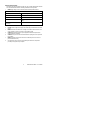
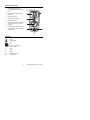
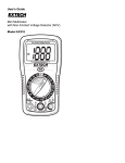
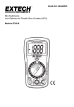
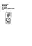
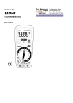
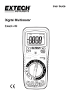
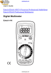
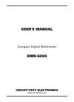
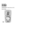
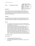
User's Guide
Mini Multimeter
with Non-Contact Voltage Detector (NCV)
Model EX310
99 Washington Street
Melrose, MA 02176
Phone 781-665-1400
Toll Free 1-800-517-8431
Visit us at www.TestEquipmentDepot.com
Introduction
Congratulations on your purchase of the Extech EX310 MultiMeter. The EX310
offers AC/DC Voltage, AC/DC Current, Resistance, Diode, and Continuity testing
plus a built-in non-contact Voltage Detector. Proper use and care of this meter
will provide many years of reliable service.
Safety
This symbol adjacent to another symbol, terminal or
operating device indicates that the operator must refer to
an explanation in the Operating Instructions to avoid
personal injury or damage to the meter.
WARNING
This WARNING symbol indicates a potentially hazardous
situation, which if not avoided, could result in death or
serious injury.
CAUTION
This CAUTION symbol indicates a potentially hazardous
situation, which if not avoided, may result damage to the
product.
MAX
600V
This symbol advises the user that the terminal(s) so
marked must not be connected to a circuit point at which
the voltage with respect to earth ground exceeds 600V.
This symbol adjacent to one or more terminals identifies
them as being associated with ranges that may, in normal
use, be subjected to particularly hazardous voltages. For
maximum safety, the meter and its test leads should not
be handled when these terminals are energized.
This symbol indicates that a device is protected
throughout by double insulation or reinforced insulation.
2
Model EX310-EU-ENG – V7.2– 05/2008
SAFETY INSTRUCTIONS
This meter has been designed for safe use, but must be operated with caution.
The rules listed below must be carefully followed for safe operation.
1.
NEVER apply voltage or current to the meter that exceeds the specified maximum:
Input Protection Limits
Function
Maximum Input
V DC or V AC
600V AC and DC
mA AC/DC
200mA DC/AC
A AC/DC
10A DC/AC (for 30 seconds max. every 15
mins.)
Resistance, Diode Test,
Continuity
250V DC/AC
2.
3.
4.
5.
6.
7.
8.
USE EXTREME CAUTION when working with high voltages.
DO NOT measure voltage if the voltage on the "COM" input jack exceeds 600V above earth
ground.
NEVER connect the meter leads across a voltage source while the function switch is in the
current, resistance, or diode mode. Doing so can damage the meter.
ALWAYS discharge filter capacitors in power supplies and disconnect the power when
making resistance or diode tests.
ALWAYS turn off power and disconnect test leads before opening the covers to replace the
fuse or battery.
NEVER operate the meter unless the back cover and the battery and fuse covers are in
place and fastened securely.
If the equipment is used in a manner not specified by the manufacturer, the protection
provided by the equipment may be impaired.
3
Model EX310-EU-ENG – V7.2– 05/2008
CAUTIONS
•
Improper use of this meter can cause damage, shock, injury or death.
Read and understand this user manual before operating the meter.
•
Always remove the test leads before replacing the battery or fuses.
•
Inspect the condition of the test leads and the meter itself for any
damage before operating the meter.
•
Use great care when making measurements if the voltages are greater
than 25VAC rms or 35VDC. These voltages are considered a shock
hazard.
•
Always discharge capacitors and remove power from the device under
test before performing Diode, Resistance or Continuity tests.
•
Voltage checks on electrical outlets can be difficult and misleading
because of the uncertainty of connection to the recessed electrical
contacts. Other means should be used to ensure that the terminals are
not "live".
•
If the equipment is used in a manner not specified by the manufacturer,
the protection provided by the equipment may be impaired.
•
This device is not a toy and must not reach children’s hands. It contains
hazardous objects as well as small parts that the children could swallow.
In case a child swallows any of them, please contact a physician
immediately
•
Do not leave batteries and packing material lying around unattended;
they can be dangerous for children if they use them as toys
•
In case the device is going to be unused for an extended period of time,
remove the batteries to prevent them from training
•
Expired or damaged batteries can cause cauterization on contact with
the skin. Always, therefore, use suitable hand gloves in such cases
•
See that the batteries are not short-circuited. Do not throw batteries into
the fire.
4
Model EX310-EU-ENG – V7.2– 05/2008
Controls and Jacks
1.
AC Voltage Detector Sensor
1
2.
AC Voltage Detector indicator light
2
3.
LCD
4.
Non-contact AC Voltage Detector
test button
5.
Rotary function dial
9
3
4
6.
10 ampere test lead jack
7.
COM test lead jack
8.
Test lead jack for voltage, milliamp,
resistance/continuity, and diode
functions
9.
Protective rubber holster (must be
removed to access the rear battery
compartment)
5
EX310
MultiMeter
CAT II - 600V
V/ /mA
8
6
7
Symbols
•)))
m
k
V
A
Continuity
Diode
Battery status
AC
DC
milli (10-3) (volts, amps)
kilo (103) (ohms)
Volts
Amps
Ω
AC
DC
Ohms
Alternating current
Direct current
5
Model EX310-EU-ENG – V7.2– 05/2008
Operating Instructions
WARNING: Risk of electrocution. High-voltage circuits, both AC and DC, are
very dangerous and should be measured with great care.
NOTE: On some low AC and DC voltage ranges, with the test leads not
connected to a device, the display may show a random, changing reading.
This is normal and is caused by the high-input sensitivity. The reading will
stabilize and give a proper measurement when connected to a circuit.
NON-CONTACT AC VOLTAGE DETECTOR
The EX310 can detect the presence of AC voltage (from 100 to 600VAC) simply
by being held very near to a voltage source.
WARNING: Test the AC voltage detector on a known live circuit before each
use.
WARNING: Before using the meter in the AC Voltage Detector mode, verify
that the battery is fresh by confirming characters appear on the LCD when the
function dial is turned to any position. Do not attempt to use the meter as an AC
Voltage Detector if the battery is weak or bad.
NON-CONTACT VOLTAGE (NCV)
The NCV function works on any rotary switch position.
1.
2.
3.
4.
Test the detector on a known live circuit before use.
Press and hold the NCV button for the duration of
the test. The meter will beep once when the button
is pushed.
Hold the top of the meter very close to the voltage
source as shown.
If voltage is present, the rim of the LCD display will
flash a bright orange and an audible warning will
sound.
6
Model EX310-EU-ENG – V7.2– 05/2008
AC VOLTAGE MEASUREMENTS
WARNING: Risk of Electrocution. The probe tips may not be long enough to
contact the live parts inside some 240V outlets for appliances because the
contacts are recessed deep in the outlets. As a result, the reading may show
0 volts when the outlet actually has voltage on it. Make sure the probe tips
are touching the metal contacts inside the outlet before assuming that no
voltage is present.
CAUTION: Do not measure AC voltages if a motor on the circuit is being
switched ON or OFF. Large voltage surges may occur that can damage the
meter.
1.
2.
3.
4.
5.
Set the function switch to the 600 VAC
position.
Insert the black test lead banana plug into
the negative COM jack. Insert red test lead
banana plug into the positive V jack.
Touch the black test probe tip to the
neutral side of the circuit.
Touch the red test probe tip to the “hot”
side of circuit.
Read the voltage in the display.
DC VOLTAGE MEASUREMENTS
CAUTION: Do not measure DC voltages if a motor on the circuit is being
switched ON or OFF. Large voltage surges may occur that can damage the
meter.
1.
2.
3.
4.
Set the function switch to the highest VDC
position.
Insert the black test lead banana plug into the
negative COM jack.
Insert the red test lead banana plug into the
positive V jack.
Touch the black test probe tip to the negative
side of the circuit. Touch the red test probe
tip to the positive side of the circuit.
Read the voltage in the display. Move the
function switch to successively lower VDC
positions to obtain a higher resolution reading.
7
Model EX310-EU-ENG – V7.2– 05/2008
BATTERY VOLTAGE TEST
CAUTION: Do not measure batteries while they are installed in the devices
they are powering. The batteries must be removed from installations before
tests can be made.
1.
2.
3.
4.
Set the function switch to the 1.5V or 9V
BAT switch position. Use the 1.5V position
for ‘AAA’, ‘AA’, ‘C’, ‘D’, and other 1.5V
batteries. Use the 9V position for square 9V
transistor batteries.
Insert the black test lead banana plug into
the negative COM jack.
Insert the red test lead banana plug into the
positive V jack.
Touch the black test probe tip to the negative
side of the battery. Touch the red test probe
tip to the positive side of the battery.
Read the voltage in the display.
1.50
EX310
MultiMeter
V
CAT II - 600V
V/ /mA
AC / DC CURRENT MEASUREMENTS
CAUTION: Do not make current measurements at 10 Amps for longer than
30 seconds. Exceeding 30 seconds may cause damage to the meter and/or
the test leads.
1.
2.
3.
4.
5.
6.
7.
Insert the black test lead banana plug into the negative COM jack.
For current measurements up to 200mA AC or DC, set the function
switch to the 200m AAC or ADC position and insert the red test lead
banana plug into the mA jack.
For current measurements up to 10A AC or DC, set the function switch
to the 10A AAC or 10A ADC position and insert the red test lead banana
plug into the 10A jack.
Remove power from the
circuit under test, then open
up the circuit at the point
where you wish to measure
current.
Touch the black test probe
tip to the negative side of the
circuit. Touch the red test
probe tip to the positive side
of the circuit.
Apply power to the circuit.
Read the current in the
display.
8
Model EX310-EU-ENG – V7.2– 05/2008
RESISTANCE MEASUREMENTS
WARNING: To avoid electric shock, disconnect power to the unit under test
and discharge all capacitors before taking any resistance measurements.
1.
2.
3.
4.
5.
Set the function switch to the highest Ω position.
Insert the black test lead banana plug into the negative COM jack.
Insert the red test lead banana plug into the
positive Ω jack.
Touch the test probe tips across the circuit or
part under test. It is best to disconnect one side
of the part under test so the rest of the circuit
will not interfere with the resistance reading.
Read the resistance in the display. Move the
function switch to successively lower Ω
positions to obtain a higher resolution reading.
CONTINUITY CHECK
WARNING: To avoid electric shock, never measure continuity on circuits
that have a voltage potential.
1.
2.
3.
4.
5.
Set the function switch to the
position.
Insert the black lead banana plug into the
negative COM jack.
Insert the red test lead banana plug into
the positive Ω jack.
Touch the test probe tips to the circuit or
wire you wish to check.
If the resistance is less than
approximately 100Ω, the audible signal
will sound. If the circuit is open, the
display will indicate “1___”.
9
Model EX310-EU-ENG – V7.2– 05/2008
DIODE TEST
1.
2.
3.
4.
5.
Set the function switch to the
position.
Insert the black test lead banana plug
into the negative COM jack and the red
test lead banana plug into the positive
jack.
Touch the test probes to the diode
under test.
A good diode will indicate approx. 700
ohms for the forward test and “1___”
for the reverse test.
A shorted diode will indicate the same
value of resistance in both the reverse
and forward test directions. An open
diode will indicate “1___” in both test
directions.
10
Model EX310-EU-ENG – V7.2– 05/2008
Maintenance
WARNING: To avoid electric shock, disconnect the test leads from any
source of voltage before removing the back cover or the battery or fuse
covers.
WARNING: To avoid electric shock, do not operate your meter until the
battery and fuse covers are in place and fastened securely.
This MultiMeter is designed to provide years of dependable service, if the
following care instructions are performed:
1.
2.
3.
4.
5.
6.
KEEP THE METER DRY. If it gets wet, wipe it off.
USE AND STORE THE METER IN NORMAL TEMPERATURES.
Temperature extremes can shorten the life of the electronic parts and
distort or melt plastic parts.
HANDLE THE METER GENTLY AND CAREFULLY. Dropping it can
damage the electronic parts or the case.
KEEP THE METER CLEAN. Wipe the case occasionally with a damp
cloth. DO NOT use chemicals, cleaning solvents, or detergents.
USE ONLY FRESH BATTERIES OF THE RECOMMENDED SIZE AND
TYPE. Remove old or weak batteries so they do not leak and damage
the unit.
IF THE METER IS TO BE STORED FOR A LONG PERIOD OF TIME,
the battery should be removed to prevent damage to the unit.
11
Model EX310-EU-ENG – V7.2– 05/2008
BATTERY INSTALLATION and LOW BATTERY INDICATION
WARNING: To avoid electric shock, disconnect the test leads from any source
of voltage before removing the battery cover. Do not operate meter unless the
battery is in place.
LOW BATTERY INDICATION
The
icon will appear in the lower left-hand corner of the display when the
battery voltage becomes low. Replace the batteries when this appears.
BATTERY REPLACEMENT
1.
Disconnect the test leads from the meter.
2.
Remove the protective rubber holster. See diagram.
3.
Remove the Phillips head screw located on the lower back of the
instrument.
4.
Remove the fuse/battery compartment cover to access the battery. See
diagram.
5.
Replace the 9V battery observing polarity.
6.
Secure the fuse/battery compartment cover using the Phillips head
screw.
7.
Place the protective rubber holster on the meter.
You, as the end user, are legally bound (Battery ordinance) to
return all used batteries and accumulators; disposal in the
household garbage is prohibited!
You can hand over your used batteries / accumulators,
gratuitously, at the collection points for our branches in your
community or wherever batteries / accumulators are sold!
Disposal
Follow the valid legal stipulations in respect of the disposal of the
device at the end of its lifecycle
12
Model EX310-EU-ENG – V7.2– 05/2008
2
1
5
3
4
1.
6
Removable Rubber Holster
2.
Meter
3.
Battery
4.
Fuses
5.
Compartment Cover
6.
Rubber Holster
REPLACING THE FUSES
WARNING: To avoid electric shock, disconnect the test leads from any source
of voltage before removing the fuse cover.
1.
Disconnect the test leads from the meter.
2.
Remove the protective rubber holster.
3.
Remove the Phillips head screw located on the lower back of the
instrument.
4.
Remove the fuse/battery compartment cover to access the fuses.
5.
Gently remove the fuse(s) and install new fuse(s) into the holder(s).
6.
Always use fuses of the proper size and value (200mA/250V fast blow
for the mA / µA ranges, 10A/250V fast blow for the A range).
7.
Secure the fuse/battery compartment cover.
8.
Place the protective rubber holster on the meter.
WARNING: To avoid electric shock, do not operate your meter until the fuse
cover is in place and fastened securely.
13
Model EX310-EU-ENG – V7.2– 05/2008
Range Specifications
Function
Range
Non-contact
AC Voltage
detector
100 to 600V Resolution & accuracy do not apply since the
meter does not display the voltage in this mode.
The lamp at the top of the meter’s display flashes
when voltage is sensed and an audible warning will
sound
Resolution
Accuracy
DC Voltage
200mV
0.1mV
(V DC)
2000mV
1mV
20V
0.01V
±(0.5% reading + 2 digits)
±(1.0% reading + 2 digits)
200V
0.1V
600V
1V
±(1.5% reading + 2 digits)
AC Voltage
(VAC)
50/60Hz
200V
0.1V
±(1.5% reading + 3 digits)
600V
1V
±(2.0% reading + 4 digits
DC Current
200mA
0.1mA
±(1.5% reading + 2 digits)
(A DC)
10A
0.01A
±(2.5% reading + 5 digits)
AC Current
(A
50/60Hz
0.1mA
±(1.8% reading + 5 digits)
0.01A
±(3.0% reading + 7 digits)
200Ω
0.1Ω
±(1.2% reading + 4 digits)
2000Ω
1Ω
20kΩ
0.01kΩ
200kΩ
0.1kΩ
2000kΩ
1kΩ
200mA
AC) 10A
Resistance
±(1.2% reading + 2 digits)
Notes:
Accuracy specifications consist of two elements:
• (% reading) – This is the accuracy of the measurement circuit.
• (+ digits) – This is the accuracy of the analog to digital converter.
Accuracy is stated at 65oF to 83oF (18oC to 28oC) and less than 75% RH.
14
Model EX310-EU-ENG – V7.2– 05/2008
General Specifications
Diode Test
Continuity Check
Input Impedance
AC Bandwidth
Display
Overrange indication
Polarity
Measurement Rate
Low Battery Indication
Battery
Fuses
Operating Temperature
Storage Temperature
Operating Humidity
Storage Humidity
Operating Altitude
Weight
Size
Approvals
Safety
Section 1.01
Bias voltage: 2.3VDC
Audible signal will sound if the resistance is
less than 100Ω
1MΩ (VDC & VAC)
50 / 60Hz
2000 count (0 to 1999) LCD
“1___” is displayed
Automatic (no indication for positive); Minus () sign for negative
2 times per second, nominal
“ ” is displayed if battery voltage drops
below operating voltage
One (1) 9V battery
mA range; 200mA/250V fast blow
A range; 10A/250V fast blow, ceramic
32ºF to 122ºF (0ºC to 50ºC)
-4oF to 140oF (-20oC to 60oC)
Max 70% up to 87ºF (31ºC) decreasing
linearly to 50% at 122ºF (50ºC)
< 80% RH
7000 ft. (2000 meters) maximum.
9.17 oz (260g) includes holster
5.8” x 2.9” x 1.6” (147 x 76 x 42mm) includes
holster
CE, UL
This meter is intended for indoor use and
protected, against the users, by double
insulation per EN61010-1 and IEC61010-1
2nd Edition (2001) to CAT II 1000V & CAT III
600V; Pollution Degree 2. The meter also
meets UL 61010-1, Second Edition (2004),
CAN/CSA C22.2 No. 61010-1, Second Edition
(2004), and UL 61010B-2-031, First Edition
(2003)
UL LISTED
The UL mark does not
indicate that this product has been evaluated
for the accuracy of its readings.
15
Model EX310-EU-ENG – V7.2– 05/2008
PER IEC1010 OVERVOLTAGE INSTALLATION CATEGORY
OVERVOLTAGE CATEGORY I
Equipment of OVERVOLTAGE CATEGORY I is equipment for connection to
circuits in which measures are taken to limit the transient overvoltages to an
appropriate low level. Note – Examples include protected electronic circuits.
OVERVOLTAGE CATEGORY II
Equipment of OVERVOLTAGE CATEGORY II is energy-consuming equipment
to be supplied from the fixed installation.
Note – Examples include household, office, and laboratory appliances.
OVERVOLTAGE CATEGORY III
Equipment of OVERVOLTAGE CATEGORY III is equipment in fixed
installations.
Note – Examples include switches in the fixed installation and some
equipment for industrial use with permanent connection to the fixed
installation.
OVERVOLTAGE CATEGORY IV
Equipment of OVERVOLTAGE CATEGORY IV is for use at the origin of the
installation.
Note – Examples include electricity meters and primary over-current
protection equipment
Copyright © 2005 Extech Instruments Corporation
All rights reserved including the right of reproduction in whole or in part in any form.
www.extech.com
16
Model EX310-EU-ENG – V7.2– 05/2008