1
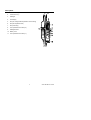
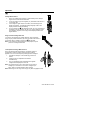
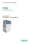
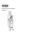
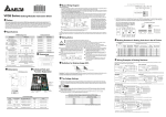
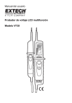
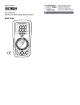
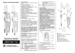
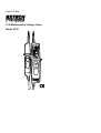
User's Guide LCD Multifunction Voltage Tester Model VT30 Introduction Congratulations on your purchase of the Extech VT30 Multifunction Voltage Tester. The VT30 measures AC voltage to 480V and DC Voltage to 690V with LCD readout, stepped voltage bargraph indicator, and LEDs for positive and negative polarity. Additional features include audible continuity beeper, low impedance test for eliminating phantom voltages, and a built-in flashlight to illuminate test connections during measurements. This meter is shipped fully tested and with proper use will provide years of reliable service. Safety International Safety Symbols This symbol, adjacent to another symbol or terminal, indicates the user must refer to the manual for further information. This symbol, adjacent to a terminal, indicates that, under normal use, hazardous voltages may be present Double insulation Safety Precautions 1. Improper use of this meter can cause damage, shock, injury or death. Read and understand this manual before use. 2. Ensure that any covers or battery doors are properly closed and secured before use. 3. Inspect the condition of the test leads and the meter itself for any damage before use. 4. Do not exceed the rated input limits. 5. Use great care when taking measurements greater than 25VAC rms or 35VDC. These voltages are considered a shock hazard. 6. Discharge capacitors and remove power from the DUT before Continuity tests. 7. Remove the batteries from the meter if the meter is to be stored for long periods. 8. Voltage measurement results on electrical outlets can be misleading because of the difficulty in making a proper connection to the electrical contacts. Safety Instructions This meter has been designed for safe use, but must be operated with caution. The rules listed below must be carefully followed for safe operation. 1. NEVER apply voltage to the meter that exceeds the specified maximum: Function VAC, VDC, Continuity Low Impedance Input Protection Limits Maximum Input 480VAC, 690VDC 3s<400V AC/690V DC 2. USE EXTREME CAUTION when working with high voltages. 3. ALWAYS discharge filter capacitors in power supplies and disconnect the power when making continuity tests. 4. ALWAYS disconnect the test leads before opening the cover to replace the battery. 5. NEVER operate the meter unless the battery cover is in place and fastened securely. 2 VT30-EU-EN V3.1 7/09 Description 1. Test Probe L1 (-) 2. Test Probe L2 (+) 3. Flashlight 4. LCD display 5. LED (AC voltage indicator [between 100 to 480V]) 6. LED (low impedance test) 7. LED (continuity) 8. Low impedance test button (L2) 9. Flashlight button 10. Battery cover 11. Low impedance test button (L1) 3 VT30-EU-EN V3.1 7/09 Operation Always test the meter on a known live circuit before taking measurements Voltage Measurement 1. Note: The voltage tester will turn on automatically when voltages higher than 4.5V AC/DC are detected. 2. Touch the positive (L2) and negative (L1) test leads to the device or circuit under test. 3. If the voltage is higher than 4.5V AC/DC, the LCD will light and display the reading. The stepped voltage bargraph scale in the display will also indicate the reading. 4. For AC voltages, the LED will light and the “AC” icon will appear in the display. For DC voltages, the “DC” icon will be displayed. If the DC voltage is negative, a minus sign will be displayed before the digital readout. Single Lead AC Voltage Detection To check for the presence of voltage (between 100V and 480V) using only the positive test lead (L2), touch the lead to the device or circuit under test. If voltage is present, the LED will light. Note: In this mode, the actual voltage is not displayed; only the presence of voltage is detected. Low Impedance Voltage Measurement Due to the lowered internal impedance, capacitive voltage is suppressed so that the reading shows the actual voltage applied. This can be used to quickly identify phantom voltages. 1. Hold the two test tips on the measuring points to be tested. 2. Press the two low impedance test buttons simultaneously. 3. The Low Impedance LED will light and the applied voltage will be displayed on the LCD. Note: The maximum duty cycle in this mode is 5 seconds for voltages up to 250V and 3 seconds for voltages up to 690V. Allow 10 minutes between each reading. Note: Measuring from hot to ground may trip any GFCI equipped circuits. 4 VT30-EU-EN V3.1 7/09 3-Phase Rotation The 3-phase rotation function indicates whether the 3 phase AC lines or mains are live and also identifies the phase orientation of the three wires before attaching them to a motor or other equipment. The phase sequence will determine the direction (Clockwise or Counterclockwise) a motor will rotate when connected. To determine clockwise rotation (P1-P2-P3) 1. 2. 3. 4. 5. 6. Touch probe L1 to any one of the three AC mains. Label this phase P1. Touch probe L2 to the other two phases. One phase will indicate “L” and one will indicate “R” Label the phase that indicates “R” as P2. Touch probe L1 to phase P2 and touch probe L2 to the remaining unlabeled AC main wire. The “R” icon will illuminate. Label this phase P3. The clockwise sequence P1-P2-P3 (also known as 1-2-3 or R-S-T) has been identified. To determine a counterclockwise rotation exchange the “L” and “R” in the procedure. Continuity Test The tester can measure resistance and alert the user if the resistance value is less than 200k. 1. Before taking a continuity test, make sure that power to the device or circuit under test is off and that all capacitors are discharged. 2. Touch the test tips to the device under test. 3. If the resistance is less than 200k, the tester will sound an audible alert; the LCD will display “000”, and the continuity LED will light. Flashlight Press and hold the button to turn the flashlight on. Release the button to turn the flashlight off. After the button is released, the light will turn off after 12 seconds (approx). 5 VT30-EU-EN V3.1 7/09 Maintenance Battery replacement 1. The icon will appear in the lower right of the display when the battery voltage becomes low. Replace the batteries when this appears. 2. Disconnect the meter from any test device or circuit before opening the tester. 3. Loosen the recessed Phillips head screw at the bottom of the tester. Do not remove the screw. 4. Hold the meter and pull the lower portion of the meter off until the batteries are exposed. 5. Replace the two ‘AAA’ batteries observing polarity and dispose of the old batteries properly. 6. Slide the meter back together and replace the screw. You, as the end user, are legally bound (Battery ordinance) to return all used batteries and accumulators; disposal in the household garbage is prohibited! You can hand over your used batteries / accumulators at collection points in your community or wherever batteries / accumulators are sold! Disposal: Follow the valid legal stipulations in respect of the disposal of the device at the end of its lifecycle Cleaning and Storage Before cleaning the tester, ensure that the test leads are not connected to any circuit or device. Wipe the meter only with a damp cloth as needed. Do not apply abrasives, solvents, or other cleaners to the surface of the meter. Store with the battery removed and avoid extreme temperature and humidity. 6 VT30-EU-EN V3.1 7/09 Specifications LCD display 1999 counts (3-1/2 digits) with bargraph and backlight Resolution 1 Volt AC Voltage range 0 to 480V ACV frequency range 50/60Hz DC Voltage range 0 to 690V Accuracy ACV ±(1.5%rdg + 5d); DCV ±(1.0%rdg + 3d) Range selection Automatic Max measuring current ≤1.0mA (400VAC); ≤1.5mA (690VDC) Response time Updates 2-3 times/sec Input Impedance 1MΩ (approx) Continuity test Range 0 to 200kΩ, guaranteed on < 50kΩ; <5µA test current Overvoltage protection 480VAC/690VDC Low impedance test 12-250VAC/DC; impedance <6kΩ; LCD enable input voltage >4.5V AC/DC Operation time: 5s<250V AC/DC Power supply 2 x “AAA” 1.5V alkaline batteries Battery life Approx. 8 hours continuous use typical Operating Temperature -10 to 55oC (14 to 131oF) Storage Temperature -30 to 60 C (-22 to 140 F) o o Operating Humidity 10 to 85% RH (non-condensing) Safety This meter is intended for origin of installation use and protected, against the users, by double insulation per EN61243-3 and IEC61243-3 to Category IV 600V and Category III 1000V; Pollution Degree 2. Approvals CE, IP64 Dimensions 240 x 78 x 40mm (9.4 x 3 x 1.6”) Weight 260G (9.2oz) Copyright © 2006 Extech Instruments Corporation All rights reserved including the right of reproduction in whole or in part in any form. 7 VT30-EU-EN V3.1 7/09