1
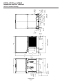
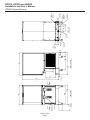
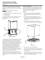
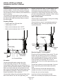
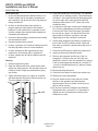
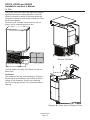
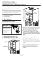
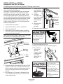
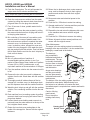
Installation and User’s Manual for
Ice Maker-Dispensers
models
HID312, HID525 and HID540
HID312, HID525 and HID540
Installation and User’s Manual
Introduction
The ice maker-dispensers covered in this manual
were designed by to be the finest on the market. Their
design is a result of Scotsman’s long experience in ice
maker-dispensers.
This manual includes the information needed to
install, start up and operate the machine. Because
there are three models covered, be sure that any
instructions apply to your unit.
HID312 is 16 inches wide and air cooled only.
Observe any caution or warning notices. They are
important and provide notice of potential hazards.
Keep this manual for future reference.
If additional technical information is needed, go to
Scotsman’s website, www.scotsman-ice.com to
download a service manual.
Note: This is a commercial product. If service is
needed on a unit in a residence, use a commercial
service company. Locate one at the website above.
HID525 is 21 inches wide and 34.9 inches tall. it is
available as an air cooled model or as a water cooled
model.
HID540 is also 21 inches wide, but it is 40.9 inches
tall. it is also available either air or water cooled.
Contents
Specifications . . . . . . . . . . . . . . . . . . . . . . . . . . . . . . . . . . . . . . . . . . . Page 2
HID312 Cabinet Drawing . . . . . . . . . . . . . . . . . . . . . . . . . . . . . . . . . . . . . . Page 3
HID525 Cabinet Drawing . . . . . . . . . . . . . . . . . . . . . . . . . . . . . . . . . . . . . . Page 4
HID540 Cabinet Drawing . . . . . . . . . . . . . . . . . . . . . . . . . . . . . . . . . . . . . . Page 5
Placement . . . . . . . . . . . . . . . . . . . . . . . . . . . . . . . . . . . . . . . . . . . . . Page 6
Counter Installations . . . . . . . . . . . . . . . . . . . . . . . . . . . . . . . . . . . . . . . . Page 7
Machine Stands . . . . . . . . . . . . . . . . . . . . . . . . . . . . . . . . . . . . . . . . . . Page 8
Component Location . . . . . . . . . . . . . . . . . . . . . . . . . . . . . . . . . . . . . . . . Page 9
Installation . . . . . . . . . . . . . . . . . . . . . . . . . . . . . . . . . . . . . . . . . . . . . Page 10
Initial Start Up . . . . . . . . . . . . . . . . . . . . . . . . . . . . . . . . . . . . . . . . . . . Page 11
Operation: Ice and Water Vending . . . . . . . . . . . . . . . . . . . . . . . . . . . . . . . . . Page 12
Controller . . . . . . . . . . . . . . . . . . . . . . . . . . . . . . . . . . . . . . . . . . . . . . Page 13
Maintenance and Cleaning . . . . . . . . . . . . . . . . . . . . . . . . . . . . . . . . . . . . . Page 14
Air filter . . . . . . . . . . . . . . . . . . . . . . . . . . . . . . . . . . . . . . . . . . . . . . . Page 15
Maintenance and Cleaning - Dispensing Bin Components . . . . . . . . . . . . . . . . . . . . Page 16
Ice level controls . . . . . . . . . . . . . . . . . . . . . . . . . . . . . . . . . . . . . . . . . . Page 17
Ice Making and Ice Dispensing System Cleaning Instructions . . . . . . . . . . . . . . . . . . . Page 18
Basic Troubleshooting . . . . . . . . . . . . . . . . . . . . . . . . . . . . . . . . . . . . . . . Page 20
Controller Diagnostics . . . . . . . . . . . . . . . . . . . . . . . . . . . . . . . . . . . . . . . Page 21
Options and Accessories . . . . . . . . . . . . . . . . . . . . . . . . . . . . . . . . . . . . . . Page 22
October 2014
Page 1
HID312, HID525 and HID540
Installation and User’s Manual
Specifications
Warranty Information
The ice maker-dispenser is designed to be installed
indoors, in a controlled environment. Although
it can operate in a wide range of air and water
temperatures, it will provide the best performance if
not subject to extremes.
The warranty statement for this product is provided
separately from this manual. Refer to it for applicable
coverage. In general warranty covers defects
in material or workmanship. It does not cover
maintenance, corrections to installations, or situations
when the machine is operated in circumstances that
exceed the limitations printed above.
Air Temperature Limitations
• Maximum: 100oF. or 38oC.
• Minimum: 50oF. or 10oC.
Product Information
Water Temperature Limitations
The product is an ice maker-dispenser. It is designed
to be installed on a countertop or on a specific
machine stand.
• Maximum: 100oF. or 38oC.
• Minimum: 40oF. or 4.4oC.
• All models require a drain. An internal drain basin
separates the ice storage bin’s drain from the drip tray
drain.
Water Pressure, potable
• Maximum: 80 PSI or 5.5 Bar
• Minimum: 20 PSI or 1.3 Bar
• A backflow preventer may be required by local
plumbing codes.
Water Pressure, condenser inlet
• Maximum: 145 PSI or 10 Bar
• Has a 7.5 ft. power cord with NEMA 5-15P plug.
• Minimum: 20 PSI or 1.3 bar; can be as low as 5
PSI or .3 Bar if clean & supplied with 45oF. water)
• Air cooled models flow air left to right and include
a cleanable air filter.
Condenser GPM
• Legs are optional. Thread size 3/8 - 16.
• 70 F. water: .25 or .95 LPM
o
• Special models are required for wall mounting.
• 50oF. water: .15 or .57 LPM
• Ice or water vending is triggered by touch free
sensors, no other activation method is available.
Water Conductivity:
• For available options and kits, see sales literature.
• Minimum: 10 microSiemens/cm
RO water may be supplied to the potable water
system, but if it has less than the above conductivity,
the water level sensor will not detect water and the
unit will not make ice.
Scotsman Ice Systems are designed and
manufactured with the highest regard for safety and
performance. They meet or exceed the standards of
UL and NSF.
Deionized water will not work and isn’t recommended.
Scotsman assumes no liability or responsibility of
any kind for products manufactured by Scotsman
that have been altered in any way, including the use
of any part and/or other components not specifically
approved by Scotsman.
Voltage
• Maximum: 126 Minimum: 104
Operating the machine outside of any of the above
limitations is considered abuse and any resulting
damage is not covered by warranty and could cause a
complete loss of warranty coverage.
Model
HID312A-1A
HID525A-1A
HID525W-1A
HID540A-1A
HID540W-1A
Electrical
115/60/1
115/60/1
115/60/1
115/60/1
115/60/1
Condenser
Air
Air
Water
Air
Water
Scotsman reserves the right to make design changes
and/or improvements at any time. Specifications and
design are subject to change without notice.
Typical Amp Draw
October 2014
Page 2
Maximum Fuse Size
15
15
15
15
15
October 2014
Page 3
10.2
4.00
OPTION LEGS
ADJUSTABLE
ICE CHUTE
REMOVABLE
AIR FILTER
AIR FLOW
34.6
13.62
FRONT VIEW
41.5
16.36
WATER CHUTE
41.3
16.25
0.3
.12
AIR FLOW
88.6
34.88
27.9
11.00
59.7
23.50
7.7
3.02
RIGHT SIDE VIEW
36.8
14.50
61.9
24.38
10.2
4.00
5.1
2.01
UTILITY
CHASE
9.7
3.80
UTILITY
CHASE
POWER
CORD
BACK VIEW
8.3
3.25
3/4" FPT
DRAIN
4.6
1.80
3/8" FLARE
WATER INLET
3
1.17
HID312, HID525 and HID540
Installation and User’s Manual
HID312 Cabinet Drawing
October 2014
Page 4
10.2
4.00
OPTION LEGS
ADJUSTABLE
ICE CHUTE
REMOVABLE
AIR FILTER
AIR FLOW
FRONT VIEW
54.2
21.36
WATER CHUTE
54
21.25
47.3
18.62
AIR FLOW
0.3
.12
88.6
34.88
27.9
11.00
7.7
3.02
RIGHT SIDE VIEW
59.7
23.50
36.8
14.50
61.9
24.38
10.2
4.00
5.1
2.01
UTILITY
CHASE
9.7
3.80
UTILITY
CHASE
POWER
CORD
3
1.17
3/4" FPT
DRAIN
17.8
7.00
12.5
4.94
18.9
7.45
5.1
2.00
BACK VIEW
3/8" FLARE
WATER INLET
3/8 FPT
CONDENSER
WATER INLET
(WC ONLY)
4.6
1.80
1/2 FPT
CONDENSER
DRAIN
(WC ONLY)
HID312, HID525 and HID540
Installation and User’s Manual
HID525 Cabinet Drawing
October 2014
Page 5
10.2
4.00
OPTION LEGS
ADJUSTABLE
ICE CHUTE
REMOVABLE
AIR FILTER
AIR FLOW
54.2
21.36
FRONT VIEW
47.3
18.62
54
21.25
AIR FLOW
0.3
.12
103.8
40.88
27.9
11.00
7.7
3.02
36.8
14.50
RIGHT SIDE VIEW
59.7
23.50
61.9
24.38
10.2
4.00
5.1
2.01
3
1.17
POWER
CORD
9.7
3.80
UTILITY
CHASE
3/4" FPT
DRAIN
17.8
7.00
BACK VIEW
12.5
4.94
18.9
7.45
5.1
2.00
3/8" FLARE
WATER INLET
3/8 FPT
CONDENSER
WATER INLET
(WC ONLY)
4.6
1.80
1/2 FPT
CONDENSER
DRAIN
(WC ONLY)
HID312, HID525 and HID540
Installation and User’s Manual
HID540 Cabinet Drawing
HID312, HID525 and HID540
Installation and User’s Manual
Placement
The location of the equipment should be selected
with care. Consideration should be given to allow
adequate space on the sides for air cooled models to
breathe.
Minimum clearances for air cooled models:
Cafeteria applications.
The unit can be placed in a cafeteria line for ice and
water. As some users sometimes dispense too much
ice, high volume use may require the drip tray to be
occasionally cleared of spilled ice.
Unpack
• 3 inches at each side
• 2 inches above, 10” more to allow auger removal
when ceiling is fixed.
• None at the back.
Air cooled models flow air left to right. More space
than the minimum at the sides will maximize
performance.
1. Separate the carton from the shipping pallet.
2. Remove any strapping holding the cabinet to the
pallet.
3. Inspect for hidden shipping damage. If any is
found, retain carton and notify carrier for potential
claim. Shipping damage is not covered by
warranty.
4. Remove bolts holding machine to pallet. Use
caution to not tip unit too far when removing bolts.
Airflow Direction
The power outlet should be located within the length
of the supplied power cord. If placed on a counter,
the counter must be strong enough to support the
weight of the unit. Space above the cabinet should be
allowed for service and maintenance. If legs will be
used, allow space for the total cabinet height.
Air cooled models in a small room will require
ventilation to exhaust the heat they produce. They
also produce some added noise from the fan.
Noise sensitive areas should consider water cooled
equipment or the machine located where the noise
from ice making is not objectionable.
Nearby infrared emitters or a window that allows
sunlight to shine on a dispensing sensor may cause
the unit to dispense ice or water without a container to
trigger it.
Unpacking
5. Remove plastic covering the drip tray.
6. Remove the protective plastic covering the panels.
The longer it is left on the panel, the harder it will
be to remove it.
7. Place unit on machine stand or on counter. If on
machine stand secure the cabinet to the machine
stand with the required fasteners.
October 2014
Page 6
HID312, HID525 and HID540
Installation and User’s Manual
Counter Installations
Units placed on a counter must either use legs or be
sealed to the counter top with food grade sealant per
local codes. To avoid disturbing the seal, complete the
installation prior to sealing.
Panel Removal
Remove one screw at bottom front of upper front
panel, swing bottom of panel forward and lift off the
unit.
Legs
Legs are optional for countertop applications. They
are not to be used on the HID dispenser when it is
placed on a machine stand.
Twist ice and
water chutes
counterclockwise and
pull down to remove.
Remove four screws
from sides of lower
front panel, pull forward
slightly and rest it
on the drip tray. If
needed, unplug sensor
connector and separate
panel from unit.
Pre-Start Inspection
Set Up
The drip tray and cup rest are shipped in place, there
is no need to attach or remove them. It is a good idea
to remove the front panels and inspect for any loose
or rubbing parts prior to installation.
Level the cabinet front to back and left to right.
Confirm there are no loose or rubbing parts.
Return splash panel and chutes to unit.
October 2014
Page 7
HID312, HID525 and HID540
Installation and User’s Manual
Machine Stands
Scotsman manufactures two machines stands for
the HID dispensers: a 16 inch wide model and a 21
inch wide model. The prior machine stands are not
suitable for use with the HID models and their use is
not recommended.
October 2014
Page 8
HID312, HID525 and HID540
Installation and User’s Manual
Component Location
Photo-Electric Eye Ice
Level Sensors
Ice Making
System
Water
Reservoir
Agitator,
Dispense Bar,
Dispense
Rotor
Compressor
Control Box
Electronic
Controller
Condenser
Compressor
Ice Dispense
Sensor
Drain Basin
and Manifold
Water Dispense
Sensor
Drip Tray
October 2014
Page 9
HID312, HID525 and HID540
Installation and User’s Manual
Installation
Installation should be done by an experienced ice
machine installer. To locate one, call the number on
the back of this manual or go to Scotsman’s website
www.scotsman-ice.com to identify a local distributor or
service company.
The machine will require power, water and drain.
Locate the water supply fitting on the lower back of
the cabinet and obtain the correct fitting to connect
the water supply.
Plumbing Fittings:
material to meet local codes. The drain basin in the
machine will act as an internal vent, no additional
vent should be required unless there is a very long
horizontal run. Drain tubing must pitch down 1/4 inch
per foot to the building drain. Insulation of drain tubing
is recommended for most environments.
Water cooled models:
Connect water or coolant supply (if using recirculating
system) to the condenser inlet.
Connect drain (or return if a recirculating system) to
the condenser drain. Use only rigid tubing. Do not
vent this drain tube.
• Potable water inlet: 3/8 male flare.
• Cabinet drain: 3/4 FPT.
• Water cooled condenser inlet: 3/8 FPT.
• Water cooled condenser drain: 1/2 FPT
Condenser
Inlet
Power
Cord
Drain Tubing
Water Cooled Utilities
Power
Cord
Condenser
Drain
Electrical Supply - 115 volt models
Potable Water
Connection
Air Cooled Utilities
All models:
Connect the potable water supply to the inlet
at the bottom back of the unit. 3/8” OD tubing
recommended. Water filters may be used but are not
required. Note that activated carbon or charcoal water
filters are used for taste and odor problems but also
take out any chlorine that the local water agency may
have added for purification. That can require more
frequent sanitization of the equipment.
Connect drain tubing to the central drain fitting at the
back of the cabinet. Use 3/4 inch rigid tubing, use
Plug the unit into a dedicated 15 amp outlet. The unit
must be the only device on the circuit. Confirm the
outlet is properly grounded and is in good condition.
Worn outlets should be replaced as they can cause
erratic operation of equipment. Do not use an
extension cord. Do not cut off the ground plug on the
power cord.
Ground fault outlets are not recommended. If ground
fault is required a ground fault breaker should be
used.
Use the services of a licensed electrician when
needed and conform to local and national codes.
Position the unit in its final location.
Level the unit front to back and left to right.
Seal to the countertop as required per local codes.
October 2014
Page 10
HID312, HID525 and HID540
Installation and User’s Manual
Initial Start Up
Final check list:
1. Is the icemaker-dispenser installed indoors, in a
location where the air and water temperatures
are controlled, and where they do not go beyond
design limitations?
2. Is there an electrical disconnect (switch or
plug as required) within sight of the installed
machine? Is the machine on a separate circuit?
Has the voltage been checked and compared to
nameplate requirements?
3. Have all of the plumbing connections been made
and checked for leaks?
4. Has the machine been leveled?
5. Is there a minimum of 3 inches of clearance at the
left and right sides of an air cooled machine?
4. Push and release the On/Off button. The machine
will start the ice making process. The code display
will show F. Air cooled models will discharge warm
air out the right side, water cooled models will
discharge warm (about 110oF.) water out of the
condenser drain.
5. In minutes ice will begin to fall into the dispensing
bin. Check ice dispensing by holding a container
in front of the Touch Free ice sensor (just below
the ice delivery spout). Ice should flow from the
spout when a container is present, and stop
dispensing when the container is removed.
6. Check water dispensing by holding a container in
front of the Touch Free water sensor. Water will
flow when a container is present and stop when it
is removed.
6. Is there clearance at the top and back of the
machine for service and utility connections?
7. Push the On/Off button to switch the machine off.
7. Is there a water shut off valve installed near the
machine?
9. Remove the top panel and the top of the ice
storage bin. Scoop out any ice in the bin and
sanitize the interior of the ice storage bin by wiping
it with a locally approved sanitizer or a mixture of
1 ounce of household bleach to 2 gallons of water,
allow to air dry.
Start Up
1. Remove upper front panel
2. Open the water hand valve, observe that water
enters the water reservoir, fills and then shuts off.
Check for leaks. Repair any leaks before going
any further.
3. Switch electrical supply on. Lights on controller
will flash and then the power light will remain on.
The code display will show O.
ON / OFF
8. Unplug or disconnect electrical power.
10.Reconnect electrical power.
11.Push the On/off button to switch the machine on.
12.Replace all covers and panels.
13.Give the owner/user the user manual, instruct
him/her in the operation and maintenance
requirements of the unit. Make sure they know
who to call for service.
14.Fill out the Customer Evaluation and Warranty
Registration form, and mail it in to Scotsman or
register the unit at Scotsman’s website (www.
scotsman-ice.com).
October 2014
Page 11
HID312, HID525 and HID540
Installation and User’s Manual
Operation: Ice and Water Vending
During ice making soft ice is compressed thru a die
and then broken off into irregular lengths. It will not be
clear and, because of melting, when dispensed it will
not be uniform in size or shape.
Other notes:
• An occasional drip may be seen from the ice
dispense chute. This is normal and is from ice melting
inside the chute. A continuous stream of water from
the ice chute indicates a restricted bin drain.
• Clear containers (glass or plastic) may not always
activate the dispense sensors. Retry with an opaque
container.
• The drip tray is not a sink and cannot tolerate
garbage. Coffee and soda should not be discarded
into it. Debris like stirring straws that are discarded
into the drip tray will likely cause a drain back up and
need to be removed as soon as they are found.
• Both dispensing and ice making are disabled
when the unit is switched off at the controller.
Dispense
Sensors
Splash panel wipe-off. Wiping the splash panel could
result in unintended dispensing. To avoid that, a
disable button has been provided. It is recessed into
the bottom of the chute panel. Push and release it to
disable dispensing for 60 seconds.
Vending Disable
Switch
Dispensing takes place when the Touch Free sensor’s
infrared beam bounces back to the sensor from a
container placed directly in front of it.
If the container is in front of the Touch Free sensor
on the left side, the ice dispensing rotor will rotate
and sweep ice over the ice dispensing chute. Ice will
continue to discharge out this chute as long as the
rotor is turning. It stops when the rotor stops.
If the user does not remove the container, ice will be
dispensed for 24 seconds and then stop.
If the container is in front of the Touch Free sensor on
the right side, the inlet water valve will open and water
will flow into the container.
If the user does not remove the container water will be
dispensed for 20 seconds and then stop.
Note: Water may dispense cloudy and then clear up in
the glass. That is normal due to air in the water and is
not an indicator of any malfunction.
Noise
This is a commercial ice machine. It contains a
powerful compressor, heavy duty gear reducer and, if
air cooled, a fan that moves a lot of air. It will produce
some noise when it is making ice. Every effort was
made during its design to minimize the sound level
but some is unavoidable.
October 2014
Page 12
HID312, HID525 and HID540
Installation and User’s Manual
Controller
All models use the same control system.
The electronic controller operates the compressor
(with fan motor), auger drive motor, dispense drive
motor and inlet water solenoid valve. It monitors:
• Reservoir water availability
• Storage bin ice level
• Call for ice dispense
• Call for water dispense
• Refrigeration pressure
• Dispense enable / disable
• Auger motor speed
• Auger motor rotation
• Any installed control options
Many of these are used to insure that the machine
does not damage itself during use. For example, it is
critical that it not attempt to make ice without water, so
if the water sensor is dry, the machine will not make
ice.
Switches - there are four switches:
There is also a code display, the codes are:
•
Dispense water - to test water dispensing
•
Dispense ice - to test ice dispensing
•
On/Off - to switch the machine on or off. Holding it
in to shut off will stop ice making immediately.
Clean - to engage the clean mode
•
Indicators - there are nine LEDs:
•
Power - Glows when controller has power
•
Status - Glows when in ice making mode
•
Time to Clean - Glows when it is time to clean the
machine
•
Water Dispense Sensed - glows when the water
dispense sensor has been triggered*
•
Ice Dispensed Sensed - glows when the ice
dispense sensor has been triggered*
•
Water Dispense - glows when the inlet water
solenoid valve has been powered*
•
Ice Dispense - glows when the ice dispense
motor has been powered*
•
Auger - glows when the auger motor is on
•
Compressor - glows when the compressor is on
O - - - F - - - b - - - E - - - C - - - d - - - 1 - - - 2 - - - 3 - - - 4 - - - for off
for ice making
for bin full
for controller error
for clean mode
for test mode
for auger rotation direction wrong
for auger speed too slow
for no water sensed
for high refrigerant pressure
If a number code is triggered, the controller will stop
ice making. A blinking code means it is a temporary
condition. Example: A blinking F occurs during the
ice making restart process; it stops blinking when the
compressor starts.
The controller will automatically restart from a water
interruption or power interruption or when a refrigerant
pressure switch has automatically reset.
To reset the control when it has been manually locked
out, Push and release the On/Off button to shut it Off
and then Push and release it again to switch it On.
* If blinking the water or ice dispensing time limit has
been met.
Note: The compressor will not restart for 4 minutes
from the time it was shut off.
October 2014
Page 13
HID312, HID525 and HID540
Installation and User’s Manual
Maintenance and Cleaning
There are five areas of maintenance:
4. Remove screws holding lower front panel to unit
and unplug lower panel sensors at the harness
connection. Set panels aside.
1. Drip tray and drain system
2. Air cooled condenser filter and condenser
Dispense
Sensor
Harness
Disconnect
3. Ice dispense bin and rotor
4. Photo eye ice level control
5. Ice making water system
Drip Tray
It is important to keep the drip tray clean of trash.
Remove any as soon as it is noticed. Pour hot water
into the tray on a regular basis to keep the drain open.
Over time the drip tray and cup rest may become
coated with scale or dirt. It can be removed to be
scrubbed at a wash sink.
1. Remove upper front panel.
2. Push in dispense disable switch.
5. Shut the machine off.
6. Pull the sink forward to disconnect it from the
drain. Plug the drain fitting with a cloth to keep it
from leaking while the drip tray is being cleaned.
Drip
Tray
3. Twist dispense chutes clockwise and pull down to
remove.
Drain
Connection
7. Wash out the drip tray and dispense chutes. Use
ice machine scale remover if needed to dissolve
scale.
8. Reverse to reassemble. Be sure drip tray is
pushed back fully into place. Insert chutes and
rotate CCW until they snap into place and stop.
October 2014
Page 14
HID312, HID525 and HID540
Installation and User’s Manual
Air filter
The air filter on the left side of the cabinet will capture
significant dust and lint during operation. As the dirt
builds up it begins to restrict air flow and causes the
refrigeration system to work longer to make ice. Clean
the air filter regularly.
To remove, pull it forward from the louvers. Do not
leave it out for extended periods of time.
Remove Top Panel
To clean, wash it at a utility sink. Return it to the unit
when clean.
Condenser.
The condenser fins may need cleaning too. Remove
the left side air grill and brush any lint and dirt off the
surface of the condenser. Vacuum any remaining
dirt. Do not damage the fins of the condenser during
cleaning.
Remove Bin Cover and Ice Delivery Chute
October 2014
Page 15
HID312, HID525 and HID540
Installation and User’s Manual
Maintenance and Cleaning - Dispensing Bin Components
The ice storage bin and rotor must be cleaned and
sanitized on a regular basis, at a minimum when the
ice making system is cleaned. Hand tools and hand
protection like rubber gloves are recommended for
this procedure.
10.Lift up and remove dispense rotor, set aside.
Note: Some steps overlap with the procedure on the
next page. This procedure can be independent of the
ice making system cleaning or can be part of it.
Dispense
Rotor
Bin Cleaning Procedure
1. Remove upper front panel.
2. Remove top panel.
3. Shut machine off.
4. Vend or melt out all ice.
Note: Only add 16 oz water to the bin at a time, as
excess water will drain out the spout.
5. Disconnect ice level control at harness.
11.Mix a solution of ice machine scale remover, such
as Scotsman Clear 1 and potable water per the
directions supplied with the scale remover.
Moving parts hazard.
Risk of personal injury.
Disconnect electrical
power before
proceeding.
6. Unplug or disconnect unit from electrical power.
7. Remove ice storage bin cover, set aside.
8. Remove agitator (rotate CCW), set aside.
9. Remove 2 thumbscrews & chute cover, set aside.
Agitator
12.Use a clean cloth and wash all the interior
surfaces of the bin and the bin cover, agitator
bar, chute cover and dispense rotor with the ice
machine scale remover solution. Rinse with clear
water.
13.Mix a 2 gallon solution of locally approved
sanitizer. A possible sanitizer solution is one
packet of Stera Sheen Green Label and 2 gallons
of warm (95o to 105oF.) potable water.
14.Use a new clean cloth and wash all the interior
surfaces of the bin and the bin cover, agitator bar,
chute cover and dispense rotor with the sanitizer
solution.
15.Return all parts to their original positions and
secure them with their original fasteners.
Chute Cover
16.Reconnect electrical power and restart the
machine.
October 2014
Page 16
HID312, HID525 and HID540
Installation and User’s Manual
Ice level controls
Clean if the controller indicates bin full and there
is no ice between the sensors.
5. Remove the chute
mounting panel.
1. Remove top front and top panels.
2. Shut machine off.
3. Disconnect ice level controls at connector.
4. Remove 3 screws and ice storage bin cover.
5. Pull each sensor grommet clip up and off.
Clip
Cover
6. Remove splash
panel, disconnect
sensors from
harness and set
panel aside.
Sensor
Grommet
6. Push grommets out of bin top.
7. Pull each sensor out of its rubber grommet. Pull
on the part closest to the grommet, not the wire.
8. Wipe the sensor lenses clean with a soft, clean
cloth. Caution - do not scratch the lens. If there
is mineral scale on the lens, ice machine scale
remover will be needed to wipe them clean.
7. Locate two 3
prong knob bolts
under the bin.
Remove them.
8. Locate bin drain
and disconnect it
from bin fitting.
9. Return each sensor to a grommet, push it in until it
snaps into place.
10.Reverse the rest of the steps to reassemble.
Dispensing Bin
The dispensing bin may be removed for cleaning or to
provide service access to other components.
1. Go thru steps 1 thru 10 of the Bin Cleaning
Procedure above.
9. Lift the bin up and
off the chassis.
Clean as needed.
2. Remove ice sweep.
3. Remove ice delivery chute and chute cover.
4. Twist and remove the water and ice dispense
chutes.
October 2014
Page 17
HID312, HID525 and HID540
Installation and User’s Manual
Ice Making and Ice Dispensing System Cleaning Instructions
Hand tools, cleaning supplies and hand protection are
recommended for this procedure.
Frequency: Recommended minimum time between
cleanings is 6 months. To aid in determining if the
machine has not been cleaned in 6 months, a Time
To Clean light will glow after 6 months of power up
time. Cleaning the machine with the following process
will reset that light and the timer that controls it. More
frequent cleanings may be required based on the
mineral content of the water, run time and potential
airborne contamination.
1. Remove both front panels.
2. Push On/Off button to shut ice making off.
7. Loosen thumb
screw holding
water reservoir
to post.
8. Lift water
reservoir to the
top of the post
and re-secure
with the thumb
screw.
Reservoir
Cleaning
Position
Thumb
Screw
9. Remove cover
from water
reservoir.
10.Vend all ice from dispenser.
3. Shut water supply off.
4. Drain water from ice making system by pulling
reservoir drain hose from plug at drain basin and
return to plug when drained.
Note: Drain into drain basin in base of unit. Sink must
be attached to unit throughout this process.
Reservoir
Drain Hose
Reservoir
Drain Plug
Drain
Basin
Moving parts hazard.
Risk of personal injury.
Disconnect electrical
power before
proceeding.
11.Remove dispense bin cover.
12.Remove cover from top of ice making system.
13.Pour cleaning
solution into
reservoir.
Caution: solution
is highly acidic.
Use rubber
gloves and Do
Not Spill.
5. Remove reservoir cover and fill with hot (110-120
degree F.) water, wait 2 minutes and drain water
from ice making system by pulling reservoir drain
hose from plug and return hose to plug when
drained.
6. Mix a solution of 12 ounces of Scotsman Clear
1 ice machine scale remover and 12 ounces of
clean, potable water.
October 2014
Page 18
Scotsman Ice Machine
Cleaner contains acids.
These compounds may cause
burns.
If swallowed, DO NOT
induce vomiting. Give large
amounts of water or milk. Call
Physician immediately. In
case of external contact, flush
with water.
KEEP OUT OF THE REACH
OF CHILDREN
HID312, HID525 and HID540
Installation and User’s Manual
14.Push the Clean button. The unit will operate the
auger motor for 30 minutes and then stop.
Note: Stop at any time by pushing the On/Off button.
15.Disconnect unit from electrical power.
16.Drain the scale remover solution from the water
system by pulling the reservoir drain hose from its
plug and return it to the plug when drained.
17.Pour 24 ounces of clean, potable water into the
reservoir.
18.Drain the water from the water system by pulling
the reservoir drain hose from its plug and return it
to the plug when drained.
19.Mix a solution of 4 ounces of ice machine scale
remover and 16 ounces of potable water. Use
this scale remover solution to washout the water
reservoir cover, ice discharge chute, ice chute
cover, ice delivery chute, storage bin cover and
inside of the ice storage bin. Also wash the sink /
drip tray and grill with this solution. Pour half down
the bin drain and the rest into the sink / drip tray to
flush out their drains.
Sanitize now.
20.Mix a 2 gallon solution of sanitizer. A
recommended sanitizer solution is one 2 oz.
packet of Stera Sheen Green Label and 2 gallons
of warm (95o to 105oF.) potable water, or an
equivalent sanitizer at a concentration of 100 ppm.
21.Pour the sanitizer solution into the reservoir until it
is full.
22.Remove the ice outlet cover and ice dispenser
agitator from the bin. Wash them with the sanitizer
solution.
23.Thoroughly wash all inside surfaces of the ice
storage bin, ice chute cover, ice discharge chute
and ice dispense chute with the sanitizer solution.
24.Wash the sink / drip tray and grill with the sanitizer
solution. Pour remaining sanitizer into the bin and
sink.
25.Drain sanitizer from ice making system by pulling
reservoir drain hose from plug and return hose to
plug when drained.
26.Loosen thumb screw holding water reservoir to
post and lower the water reservoir to the top of the
slot, retighten thumb screw.
27.Return the ice chute cover and agitator to the
inside of the storage bin. Secure with the original
fasteners.
28.Return the ice discharge chute, water reservoir
cover, and ice dispense chute to their original
positions and secure them with their original
fasteners.
29.Reconnect water and electrical power to the
machine.
30.Push the On / Off button to restart ice making.
31.Operate machine for 5 minutes and then push the
On / Off button to stop ice making.
32.Discard the ice and return the dispense bin cover
to the machine and secure with the original
screws.
33.Push the On / Off button to resume ice making.
34.Return all panels to their normal positions and
secure with the original screws.
Other Maintenance
The auger in the ice making system is centered by
bearings at the top and bottom. It is also sealed from
leaking by a water seal at the bottom.
The bearings
are permanently
lubricated and need no
maintenance. The can
be visually checked for
obvious wear or damage
but there is no need to
add lubrication.
Bearing
Auger motor bearings
and the gear reducer
are also permanently
lubricated and need no
maintenance.
The bottom of the ice making system should be
checked for water leaks. Water draining from
the bottom is an indication of a water seal leak.
Immediate repair is required when a water seal leak is
discovered.
Caution: Moving
parts hazard.
Do not touch the
rotating shaft at any
time.
October 2014
Page 19
Rotating Shaft Do NOT Touch
HID312, HID525 and HID540
Installation and User’s Manual
Basic Troubleshooting
See the separate HID service manual for more advanced troubleshooting information.
Symptom
No ice is dispensed
Possible Cause
No ice in bin
Dispense motor not turning
No water is dispensed
Water drips from spout
Dispense motor working,
but ice in bin not moving
No water to unit.
Water valve not opening
May be normal
Bin drain may be plugged.
Air in the water
Dispensed water is
cloudy, but clears up in a
few minutes
Water leak near front
Drip tray not in position
Water filling drip tray
Main drain plugged
Probable Correction
Unit in Off mode. Remove upper front panel and
check controller code, push On/Off button to restart.
No water to unit. Controller shows code 3. Restore
water supply.
No power to unit, power light on controller is off.
Restore power.
High pressure control opened. Controller shows
code 4, water interrupted to water cooled model.
Restore water and reset controller.
Ice level control sensing full bin falsely. Controller
shows b. Clean ice level control sensors.
Remove upper front panel, check controller indicator
lights. Hold container in front of sensor, does the
Ice Dispense Sensed light glow? If no, sensor is
not detecting the container. If yes, does the Ice
Dispense light glow? If yes, push Dispense Ice
button. Does the motor activate? If yes, go to next
row. If no, check for voltage at motor. If no voltage,
replace controller. If voltage at motor, replace
motor.
Agitator or rotor not turning, remove all ice and
inspect for damage to agitator and rotor.
Restore water.
Remove upper front panel, check controller indicator
lights. Hold container in front of sensor, does the
Water Dispense Sensed light glow? If no, sensor is
not detecting the container. If yes, does the Water
Dispense light glow? If yes, push Dispense Water
button. Does the water valve activate? If no, check
for voltage at valve. If no voltage, replace controller.
If voltage at valve, replace valve.
A few drops per minute is normal.
Check bin drain tube at basin.
This is normal and can vary depending upon how
much air is in the water. May be improved by
lowering water pressure to the unit.
Confirm drip tray is pushed all the way back and
touching the base.
Remove splash panel and inspect basin for standing
water. Clear drain to and from basin.
October 2014
Page 20
HID312, HID525 and HID540
Installation and User’s Manual
Controller Diagnostics
Code or Light Action
O
Probable Cause
Unit manually switched off
Suggested Action
If desired, switch unit on.
F
Freeze mode
None, unit is making ice.
b
Bin sensors sense bin full
Check if bin is full.
E
Corrupted memory
Replace controller
C
Clean mode
Continue clean mode
d
Test mode
1
Auger motor rotated auger
backwards.
2
3
Auger motor stalled or operating
slowly
No water in reservoir
None, allow unit to finish test
mode.
Replace auger motor. Check water
seal area for leaks, replace seal if
leaking.
Clean ice making system and retry.
4
High pressure cut out open
Water dispense sensed light
blinking
Water dispense light blinking
Ice dispense sensed light blinking
Ice dispense light blinking
Container positioned in front of
water dispense sensor for more
than 24 seconds
Status light is on
Unit is in ice making mode
Time to Clean light is on
Unit has not been cleaned for at
least 6 months
Water Dispensed Sensed light is
on
Ice Dispensed Sensed light is on
A container is in front of the sensor Normal during water dispensing
Water Dispense light is on
Water solenoid has been activated
Ice Dispense light is on
Bin drive motor has been activated Normal during ice dispensing
Auger light is on
Auger motor is active
Normal when making ice
Compressor light is on
Compressor is active
Normal when making ice
Restore water. If there is water,
is it too pure? Are sensor wires
connected?
Check fan motor on air cooled or
water supply on water cooled.
Normal, controller has a time limit
for dispensing. Remove container.
Container positioned in front of ice
dispense sensor for more than 20
seconds.
Normal, may not be making ice if
bin is full
Clean unit
A container is in front of the sensor Normal during ice dispensing
October 2014
Page 21
Normal during water dispensing
HID312, HID525 and HID540
Installation and User’s Manual
Options and Accessories
October 2014
Page 22
SCOTSMAN ICE SYSTEMS
775 Corporate Woods Parkway
Vernon Hills, IL 60061
800-726-8762
www.scotsman-ice.com
17-3492-01


![Quest Elite 2000-Hydro Carbon Service Manual [ 033857 ]](http://vs1.manualzilla.com/store/data/006004650_1-f9b7a3a43e3300051ad30d285820ff91-150x150.png)