1
IUSS HEALTH
FACILITY GUIDES
Facility Assembly
Schedule Toolkit
(FAST) briefing tool
[Proposal V.3]
September 2014
Task Team: D:02.2
Supported by:
Document tracking
Version
Date
Name
Proposal V.2
Proposal V.3
July 2014
September 2014
Dirk Conradie
Dirk Conradie
INFORMATION
NOTES
Form:
Health facility guides
Status:
Proposal V.3, September 2014
Title:
Facility Assembly Schedule
Toolkit (FAST) briefing tool
Description:
FAST is a case-based reasoning and rule-based drag-and-drop software tool
that enables the briefing team to quickly assemble a schedule of
accommodation by using predefined or user-defined assemblies and compare
it against a norm or against other comparable precedent facilities.
CSIR 59C1119 D:02.2 - 001
Reference:
Authors:
Stakeholders:
Endorsements:
IUSS N and S task group D:02.2
National Department of Health, Provincial Departments of Health and Public
Works
The document is endorsed by the CSIR
Endorsements pending:
Submitted to the IUSS Norms and Standards Working Group for endorsement
Supersedes:
N/A
Accessing of these guides
This publication is received by the National Department of Health (NDoH), IUSS Steering Committee
Chairman, Dr Massoud Shaker and Acting Cluster Manager: Health Facilities and Infrastructure
Management, Mr Ndinannyi Mphaphuli. Feedback is welcome.
The CSIR and the NDoH retain the moral rights conferred upon them as author by section 20(1) of the
Copyright Act, No. 98 of 1978, as amended. Use of text, figures or illustrations from this report in any
future documentation, media reports, publications, competition entries and advertising or marketing
material is solely at the discretion of the Health Infrastructure Norms Advisory Committee and should
clearly reference the source. This publication may not be altered without the express permission of the
Health Infrastructure Norms Advisory Committee. This document (or its updates) is available freely at
www.iussonline.co.za or the forthcoming Department webportal.
Application and development process
These IUSS voluntary standard/ guidance documents have been prepared as national Guidelines,
Norms and Standards by the National Department of Health for the benefit of all South Africans. They are
for use by those involved in the procurement, design, management and commissioning of public
healthcare infrastructure. It may also be useful information and reference to private sector healthcare
providers.
Use of the guidance in this documentation does not dissolve professional responsibilities of the
implementing parties, and it remains incumbent on the relevant authorities and professionals to ensure
that these are applied with due diligence, and where appropriate, deviations processes are exercised.
The development process adopted by the IUSS team was to consolidate information from a range of
sources including local and international literature, expert opinion, practice and expert group
workshop/s into a first level discussion status document. This was then released for public comment
through the project website, as well as national and provincial channels. Feedback and further
development was consolidated into a second level development status document which again was
released for comment and rigorous technical review. Further feedback was incorporated into proposal
status documents and formally submitted to the National Department of Health. Once signed off, the
documents have been gazetted, at which stage documents reach approved status.
At all development stages documents may go through various drafts and will be assigned a version
number and date. The National Department of Health will establish a Health Infrastructure Norms
Advisory Committee, which will be responsible for the periodic review and formal update of documents
and tools. Documents and tools should therefore always be retrieved from the website repository
www.iussonline.co.za or Department webportal (forthcoming) to ensure that the latest version is being
used.
The guidelines are for public reference information and for application by Provincial Departments of
Health in the planning and implementation of public sector health facilities. The approved guidelines will
be applicable to the planning, design and implementation of all new public-sector building projects
(including additions and alterations to existing facilities). Any deviations from the voluntary
standards are to be motivated during the Infrastructure Delivery Management Systems (IDMS) gateway
approval process. The guidelines should not be seen as necessitating the alteration and upgrading
of any existing healthcare facilities.
Acknowledgements
This publication has been funded by the NDoH.
Acknowledgements
Principle author Dr D.C.U Conradie
Focus Areas 1 and 5 – Norms and Standards, Cost Norms Working Group
Consultants that measured the list of facilities listed below, specifically Deon Steyn and Claude Kraëmer
from SCION Architects and Project Management, and Bruce and Bryan Brinkman from B4 Architects that
over and above their measuring assignment also designed a hypothetical hospital.
The software is the result of the input of discussions with many people in various task teams of the IUSS
project. The following individuals deserve special mention:
Carlien Steyn (quantity surveyor)
Hennie Cloete (NDoH)
Edwina Fleming (CSIR)
Richard Hussey (NDoH)
Magda Coetzer (NDoH)
Geoff Abbott (CSIR)
Peta de Jager (CSIR)
Alex van den Berg (architect)
Acknowledgements also to Janine Smit the editor, Sheldon Bole, Claire du Trevou, Kumirai Tichaona and
Mokete Mokete
The facilities listed below have been analysed in detail by means of the CSIR’s functional space
classification and department classification to inform the types and sizes of different spaces, space
assemblies, departments and the fundamental relationships between the four main space categories of
workspace, workspace support, core and structure:
•
•
•
•
•
•
•
•
•
•
•
•
•
•
•
•
•
•
•
•
•
•
•
Gamopedi Clinic
Grassy Park Clinic
Holy Cross Clinic
Holy Cross Hospital
Hypothetical medical ward (Brinkman)
Johan Deo Clinic
Khayelitsha District Hospital
Kimberley Mental Health Facility
Kwanokuthula CHC
Large clinic
Mitchells Plain District Hospital
Mitchells Plain Ward
Moloto Clinic
Moses Kotane Hospital
Natalspruit Hospital
Hypothetical NDoH medical ward
Hypothetical NDoH mental health ward
Paarl Hospital
Small clinic
Uzimkulu Clinic
Valkenberg Hospital
Worcester Hospital
Waterfall Hospital operating theatres
The abovementioned facilities provided useful insights into the current space usage patterns and
provided realistic scalability and testing for the software development.
Table of contents
FAST USER GUIDE SOFTWARE CONVENTIONS .................................................................. IV
OVERVIEW ...................................................................................................................... VI
COLOURS LEGEND .......................................................................................................... VII
PART A – SOFTWARE DESIGN PHILOSOPHY ....................................................................... 1
Introduction ............................................................................................................................. 1
The case-based reasoning (CBR) aspect of FAST ........................................................................ 2
The disadvantages and caveats of case-based reasoning ............................................................ 3
The rule-based reasoning (RBR) aspect of FAST ......................................................................... 3
CBR compared to other methods .............................................................................................. 4
Design and planning principles .................................................................................................. 6
General design and planning principles .......................................................................................................... 6
PART B – USE OF THE FAST SOFTWARE ............................................................................. 7
Login ........................................................................................................................................ 7
Define facility ........................................................................................................................... 7
Space assembly dashboard (create design menu item) .............................................................. 9
Assembly design from ROOM DETAIL LIBRARY .............................................................................................. 9
Assemble design from ASSEMBLY LIBRARY .................................................................................................. 10
Use of DESIGN COMPARATOR ...................................................................................................................... 11
Create template design target ...................................................................................................................... 13
Delete actions ............................................................................................................................................... 14
Space target dashboard (define design targets menu item) ...................................................... 18
THE ESPACE PARAMETRIC RULE DEFINITION AND AD HOC SPATIAL ANALYSIS
LANGUAGE ..................................................................................................................... 21
Introduction ........................................................................................................................... 21
The ESPACE interactive language ............................................................................................ 22
How to develop an ESPACE applet........................................................................................... 24
STEP 1: Declare applet variables ................................................................................................................... 24
STEP 2: Calculate % core space ..................................................................................................................... 25
STEP 3: Calculate result to be returned ........................................................................................................ 25
Example of an ESPACE applet .................................................................................................. 30
APPENDIX A – FORMAL ESPACE LANGUAGE SPECIFICATION ............................................ 34
APPENDIX B - INTERFACING TO OTHER SYSTEMS ............................................................ 36
APPENDIX C – FUNCTIONAL SPACE CLASSIFICATION ........................................................ 40
APPENDIX D – DEPARTMENT CLASSIFICATION ................................................................ 59
REFERENCES ................................................................................................................... 67
List of figures
Figure 1: The IUSS strategic planning tools ........................................................................................................... vi
Figure 2: A typical example of the FAST drag-and-drop interface .......................................................................... 1
Figure 3: Case-based reasoning compared to concept selection (collated by author from Kolodner (1993:18),
Ulrich et al. (1995) and Pugh (1996)) ...................................................................................................................... 5
Figure 4: FAST main form. Provides access to all other features ........................................................................... 7
Figure 5: Current Health Facility form that is used to define the main characteristics of the design .................... 8
Figure 6: Create a design from ROOM DETAIL LIBRARY (Drag from 1 and Drop at 2 or 3) .................................... 9
Figure 7: FAST drawing display of room AAAD, a four-bed unit, excluding en suite that is 42.21 m² .................. 10
Figure 8: Create a design from the ASSEMBLY LIBRARY (Drag from 1 and Drop at any position 2) .................... 11
Figure 9: The FAST DESIGN COMPARATOR allows convenient comparison between two designs...................... 12
Figure 10: Select a design from the design repository for insertion into the DESIGN COMPARATOR ................. 13
Figure 11: Create a new functional unit design target from a design assembly. (Drag from 1 and Drop at
position 2) ............................................................................................................................................................. 14
Figure 12: Delete a specific room from the DESIGN ASSEMBLY (Step 1 and 2) (Drag from 1 and Drop at 2) ..... 15
Figure 13: Delete specific design assembly (Step 1 and 2) (Drag from 1 and Drop at 2) ..................................... 15
Figure 14: Delete entire design assembly (Step 1 and 2) (Drag from 1 and Drop at 2) ....................................... 16
Figure 15: Delete design comparator (Step 1 and 2) (Drag from 1 and Drop at 2).............................................. 16
Figure 16: Delete assembly library item (Step 1 and 2) (Drag from 1 and Drop at 2).......................................... 17
Figure 17: Delete entire project permanently from the design repository (Step 1 and 2) (Drag from 1 and Drop
at 2)....................................................................................................................................................................... 17
Figure 18: Delete entire project from design repository (Step 3 and 4) (Drag from 3 and Drop at 4) ................ 18
Figure 19: Create design target from FUNCTIONAL UNIT LIST phase 1 (Drag from 1 and Drop at 2).................. 19
Figure 20: Create design target from FUNCTIONAL UNIT LIST phase 2 ................................................................ 20
Figure 21: FAST interactive rule and ad hoc query builder................................................................................... 22
Figure 22: Result of query in interactive environment ......................................................................................... 23
Figure 23: The yellow highlighted block indicates that the area in m² is the result of a resolved rule ................ 24
Figure 24: ESPACE applet to calculate department areas .................................................................................... 31
Figure 25: The applet section of the Interactive Query Builder ........................................................................... 32
Figure 26: The FAST comma delimited interface standard................................................................................... 36
Figure 27: Select a FAST comma delimited import file ......................................................................................... 38
Figure 28: Select a comma delimited file with a .txt extension ............................................................................ 39
Figure 29: Confirm import of FAST comma delimited import file ........................................................................ 39
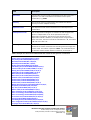
List of tables
Table 1: FAST User Guide software conventions ................................................................................................... iv
Table 2: Entering data in FAST ................................................................................................................................ v
Table 3: IUSS: General hospital support (GNS) reference documents ................................................................. vii
Table 4: A comparison between case-based, rule-based and model-based reasoning (collated by author) ......... 5
Table 5: Implementation of Facility Level in FAST .................................................................................................. 8
Table 6: Summary of ESPACE functions ................................................................................................................ 26
Table 7: The FAST comma delimited exchange format ........................................................................................ 36
Table 8: Example of a FAST comma delimited file that contains all the spaces for a small clinic ........................ 37
FAST User Guide software conventions
A wide range of terms are used to describe specific aspects of FAST. Many of these are used in slightly
different contexts by different people. To ensure that there is no uncertainty regarding the intended meaning
in FAST, lists of specific terms used in FAST are included.
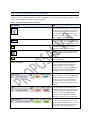
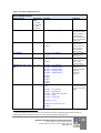
Table 1: FAST User Guide software conventions
Convention
Use
This is a FAST action. When a user drops
an object on this target, then a specific
action will be executed depending on the
type of object. Many combinations are
possible. There are currently six actions
that can be combined with objects.
All objects in FAST are coloured light blue
(cyan). You can drag this object to another
object target, or to an action, or vice versa.
Drag
Press the left mouse button and hold
down until object target is reached.
FAST drag-in-progress icon. When a user
invokes a drag on a FAST object, this icon
is displayed.
Drop
Position cursor over object target and
release left button.
<Space_ASSEMBLY>
Microsoft Access database table name.
You can use Microsoft Excel directly to
extract data from FAST for external
analysis purposes. <Space_ASSEMBLY> is
the most important table, because the
briefing space list is assembled here.
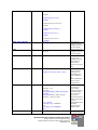
This target example indicates that the
number of beds are underprovided, being
an actual 108 against a target of 120. The
actual m² area is also smaller than the
minimum in the range that should be
between 1 254.96 and 1 387.06 m² in this
example.
This target example indicates that the
number of beds are overprovided, being
an actual 76 against a target of 70. The
actual m² area is also larger than the
maximum in the range that should be
886.45 m², to 979.77 m² in this example.
This target example indicates that the
number of consulting rooms is on target,
being 2 against a target of 2. The actual m²
area is also within the range that should
be between 22.82 m² and 25.22 m².
The following basic data entry rules should be adhered to in order to facilitate sorting and retrieval of data:
•
•
•
Entries should be done in English (facility name and descriptions).
There should be no spaces leading any entry.
Capital letters should preferably be used for classifications and codes.
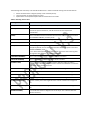
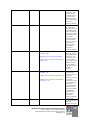
Table 2: Entering data in FAST
Data type
Use
(AREA)
This is an area in m² used in cases such as a space area.
(CLASS)
This is a classification code that should not exceed 24 characters for the
functional space classification, and 48 characters for the department
classification.
(CODE)
This is a code that should not exceed 24 characters and is for example used for
the ASSEMBLY LIBRARY, Assembly Code.
(RULE NAME)
This is the rule name and could be up to 48 characters long.
(DESCRIPTION)
This is a general description and can be up to 255 characters long.
(RULE)
Is a code fragment or applet that executes interactively in the FAST Interactive
Rule/Query Builder or fires during the allocation of derived spaces in the FAST
DESIGN ASSEMBLY panel.
It is a memo field type that can contain 65 535 characters when entering data
through the user interface, i.e. applet development.
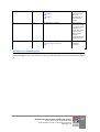
(TELEPHONE NUMBER)
This is a structured field that is used for telephone numbers.
(CELLULAR NUMBER)
This is a structured field that is used for cellular numbers.
(LOOKUP CODE)
This is a code that is looked up from another definition table. Normally a
friendly name is displayed while the code is stored in the database. In FAST the
code does not exceed 64 characters.
(LATITUDE DEGREE)
It is the latitude degree that is a whole number in the range 0 to 90.
(LATITUDE MINUTES)
It is the minute part of the latitude and is a whole number in the range 0 to 59.
(LATITUDE SECONDS)
It is the second part of the latitude and is a whole number in the range 0 to 59.
(LONGITUDE DEGREE)
It is the longitude degree that is a whole number in the range 0 to 180.
(LONGITUDE MINUTES)
It is the minute part of the longitude and is a whole number in the range 0 to
59.
(LONGITUDE SECONDS)
It is the second part of the longitude and is a whole number in the range 0 to
59.
(DECIMAL DEGREE)
It is a field that contains a degree such as site slope. It is a decimal with twodecimal accuracy.
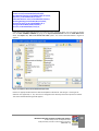
OVERVIEW
This document describes the software design philosophy and operation of the Facility Assembly Schedule
Toolkit (FAST) that is used to prepare and check the accommodation schedule of new facilities, as well as
additions and alterations to existing facilities against a given set of target norms. FAST provides output to the
Departmental Cost Calculator to estimate the construction cost. It is part of a hierarchy of strategic software
tools that start with the Infrastructure Optimisation Planning Toolkit (IOPT) at the top, the Planning Unit
Calculator/Translator, Order of Magnitude Cost Calculator, Facility Assembly Schedule Toolkit and
Departmental Cost Calculator (Figure 1).
Figure 1: The IUSS strategic planning tools
The main input into FAST originates from the Planning Unit Calculator in the form of functional planning units.
Once a facility has been defined, FAST is able to provide output to the Departmental Cost Calculator where the
construction cost can be estimated (Figure 1).
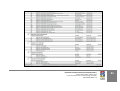
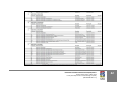
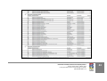
Users of FAST should refer to all other IUSS documents in order to understand the design philosophy for the
Clinical Services, Support Services, Healthcare Environment/Cross-cutting Issues and Procurement and
Operation. You will notice in Table 3 that all aspects are important, placing a significant burden on the design
team and the FAST user. However, the case-based reasoning (CBR) and rule-based design of FAST are intended
to make it as easy as possible for the user by reminding him/her of the requirements by inter alia providing
contextual spatial assemblies.
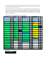
Table 3: IUSS: General hospital support (GNS) reference documents
Adult inpatient
services
Clinical and
specialised diagnostic
laboratory guidelines
Mental health
Adult critical care
Emergency centres
x
Catering services
for hospitals
x
x
x
Adult oncology
facilities
x
Paediatrics and
neonatal facilities
Pharmacy
x
x
x
Primary healthcare
facilities
Diagnostic radiology
x
x
Adult post-acute
services
x
Facilities for surgical
procedures
x
TB services
x
Consultants
Administrators
Related documents
Laundry and
linen
department
Hospital
mortuary
services
Nursing
education
institutions
Health facility
residential
Central sterile
service
department
Training and
resource centre
Waste disposal
Generic room
requirements
x
Hospital design principles
x
Integrated
infrastructure
planning
Briefing manual
x
x
x
x
x
Building engineering
services
x
Space guidelines
x
x
Environment and
sustainability
x
Cost guidelines
x
Materials and finishes
x
Future healthcare
environments
x
x
Healthcare technology
x
x
Inclusive environments
x
x
x
x
x
Infection prevention and
control
Information technology
and infrastructure
x
x
x
Procurement
Commissioning
health facilities
Maintenance
Decommissioning
Capacity
development
Recommended
Essential
Recommended
PROCUREMENT
AND OPERATION
Essential
Recommended
HEALTHCARE
ENVIRONMENT/CROSSCUTTING ISSUES
Regulations
Adult physical
rehabilitation
Colours legend
Essential
x
Administration
and related
services
General hospital
support services
x
Maternity care
facilities
Outpatient facilities
Recommended
SUPPORT
SERVICES
Essential
CLINICAL SERVICES
x
x
x
x
x
x
PART A – SOFTWARE DESIGN PHILOSOPHY
Introduction
FAST is a case- and rule-based
drag-and-drop software tool that
enables the professional health
facility design team to quickly
assemble a list of accommodation
by using predefined assemblies
and compare it against a norm or
against other comparable
precedent facilities.
FAST is a novel briefing tool to facilitate the creation of health building
briefs. The prototype was demonstrated to various groups, such as the
IUSS Cost Norms Working Group and at the 2013 SAFHE Conference in
Cape Town. On the basis of subsequent comments and discussions, the
fundamental software capabilities were determined and are
incorporated in FAST v2.0. The essential purpose of this software tool is
to effectively and efficiently assist in the translation of the strategic
requirements for a particular new health facility into a detailed spatial
design brief for use by the professional team such as the architects,
Quantity Surveyors and NDoH.
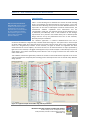
The software application is relational database-based and uses a
convenient and efficient ‘drag-and-drop’ interface illustrated in Figure 2. The system uses a novel concept
of design objects (light blue coloured blocks) and actions (square blocks with icons) implemented by
means of a drag-and-drop interface. At the moment, six types of actions are supported and when
combined with the various objects, more than 25 tasks can be achieved. When an object (indicated by
light blue on the interface) is dragged and dropped on top of another object or alternatively on top of an
action button, the system automatically knows what the user is trying to achieve from the context and
order of the action.
This software architecture significantly reduces the number of command buttons required on the screen
and also simplifies the complexity of the briefing process that requires the user to consider many different
design options.
Figure 2: A typical example of the FAST drag-and-drop interface
INFRASTRUCTURE UNIT SUPPORT SYSTEMS (IUSS) PROJECT
Health Facility Guides: 10 September 2014
Facility Assembly Schedule Toolkit briefing tool (FAST)
[PROPOSAL V.3]
1
The case-based reasoning (CBR) aspect of FAST
CBR is one of the two fundamental approaches that have been used in the design of FAST. CBR has several
advantages that make it an appropriate method to use in FAST. The list below has been collated and
adapted from Kolodner (1993). In terms of an IUSS project, a case could range from a single room such as
a bed unit, an assembly of rooms such as a medical ward, or it could be an entire health facility. The
following advantages specifically related to the architectural briefing and design process as implemented
in FAST can be identified:
1.
2.
3.
4.
5.
6.
7.
8.
9.
10.
11.
12.
13.
CBR allows the designer to propose solutions to design problems quickly, because it avoids the time
necessary to derive those answers from scratch.
CBR allows a designer to propose solutions in domains that are not completely understood. This is of
particular importance to the advanced planning that is necessary to design and build complex
facilities such as hospitals. Although extensive IUSS Health Facility guides have been developed, not
everything in the design of a complex health facility can be expressed in terms of mathematical rules.
Remembering previous designs is particularly useful in warning of the potential for problems that
have occurred in the past, alerting a designer to take action to avoid previous mistakes.
CBR can be used as a communication tool between designers and other less design-literate
participants to clearly communicate the design intentions.
Cases help a designer to focus his design activity on important parts of a problem by pointing out
what features of a problem are the important ones.
When CBR is used to solve problems, solutions can be justified by the cases they are derived from. In
a domain where it is difficult to evaluate solutions objectively, such as architectural design, CBR has
the advantage of providing illustrations of the effects of particular solutions.
CBR can be designed to anticipate potential problems as natural part of the reasoning process.
Unsuccessful experiences with past solutions can be used in case-based systems to anticipate
possible problems that might result from solving a design problem a certain way. In general, this
capability adds efficiency. In architectural design anticipation of problems is critical.
CBR provides a way for designers and computers to interact in a realistic way. CBR is fundamentally
inspired by human behaviour. Certain tasks in design, such as the calculation of energy consumption
or acoustic performance, are easier for a computer to achieve, whereas aesthetic design decisions are
best decided by the designer. Designers are good with creative reasoning, but poor at remembering
the full range of applicable cases. Humans tend to be biased in their memory or as novices they have
not yet had the experiences they need to solve the problem. During an interview of the professional
team involved in a large and complex construction project, this fact was emphasised.
The knowledge acquisition for a CBR system is natural. Concrete examples rather than piecemeal
rules can be used. Experts, such as experienced health practitioners, find it difficult to report the
knowledge they use to solve problems. They are quite at home reporting their experiences and
discussing the ways in which cases are different from one another.
CBR should be considered when it is difficult to formulate domain rules, but where cases are
available. Formulating specific rules is difficult in weak theory domains such as architectural briefing
and design. In this domain knowledge is very difficult to obtain, incomplete, uncertain or sometimes
inconsistent. It is impossible to formulate rules when there is a great amount of variability in design
situations that should have the same outcome.
CBR can be considered when rules that can be formulated require more input information than what
is normally available. This may be due to incomplete specified problems, or the fact that the
knowledge required is not available at design (problem-solving) time. This is often the case in the
construction industry and fast-track projects where all project information is not available upfront.
CBR should be considered when it is too complex (expensive in computational terms) to use rules
because the average rule chain is too long.
CBR should be used when generally applicable knowledge is not sufficient to solve a problem. This
could be due to the fact that knowledge changes with context, or because some of the knowledge
required to solve the problem is used only under special circumstances.
INFRASTRUCTURE UNIT SUPPORT SYSTEMS (IUSS) PROJECT
Health Facility Guides: 10 September 2014
Facility Assembly Schedule Toolkit briefing tool (FAST)
[PROPOSAL V.3]
2
14. CBR should be considered when a case library already exists. In the IUSS project a number of health
facilities have already been analysed and is available in structured format.
15. When no fast computation method exists for deriving a solution from scratch, CBR allows new
solutions to be derived from precedent ones. Health facilities can be quickly configured by using
different exemplar department and architectural assemblies.
16. When there is no fast computational method for evaluating a solution, or when there are so many
unknowns that evaluation methods are unusable or difficult to use, CBR provides an alternative.
17. CBR allows evaluation of solutions when no direct algorithmic method is available for evaluation.
18. Cases are useful in interpreting open-ended and ill-defined concepts.
The disadvantages and caveats of case-based reasoning
CBR has several disadvantages and caveats in architectural design that should also be considered. The list
below has been collated and adapted from Kolodner (1993):
1.
2.
3.
4.
5.
6.
7.
CBR requires cases or spatial assemblies in the context of this document. Traditionally the effort in
1
building a CBR system went into case collection. It is apparent from a study and interviews with the
designers of other CBR systems that it can be an enormous effort. To be successful in the
architectural profession and the construction industry it should not require such extraordinary
efforts. The case library should be automatically assembled during the normal professional design
activities.
For CBR to be useful and reliable, cases with similar problem statements should have similar
solutions. CBR is based on the premise that situations recur in a predictable way. Adaptation modifies
old solutions to fit new requirements. If a domain is discontinuous where similar situations require
wildly different kinds of solutions, then CBR cannot be used and would be misleading. This is
unfortunately only partially true in architecture, because creative designers do not always solve
related design problems in a similar way.
CBR solutions are not guaranteed to be optimal and in health briefing and design it unlikely that this
ambitious goal would ever be achieved. The full range of possible design solutions is usually not
explored in a CBR-system intended for design support. Optimal or more creative solutions may be
missed due to time constraints or incomplete knowledge of the design team. This is generally a
problem in any heuristic system. The designer cannot escape his responsibilities; however, the CBR
system will remind him of design aspects he might have forgotten and make sure that essential
spaces are not forgotten.
An inexperienced case-based user might be tempted to use old cases blindly, relying on previous
experience without validating it properly in the new situation.
A case-based user might allow cases to bias him or her too much in solving a new problem.
Case libraries require considerable storage space. In the design of CBR-systems, special consideration
must be given to ensure a long life of the case with changing technology. A large sum of money in
terms of intellectual capital, time and effort is encapsulated in the case library. Persistence of data is
therefore of paramount importance.
Inexperienced people are often not reminded of the most appropriate sets of cases when they are
reasoning.
The rule-based reasoning (RBR) aspect of FAST
A RBR system has also been implemented in FAST alongside the CBR system to calculate derived spatial
sizes, where the actual size of the space can only be known in the context of the final design. The RBRsystem has been implemented by means of an interpretive spatial programming language called ESPACE.
A simple example of a rule is the contextual calculation of the amount of secondary circulation space in a
ward when a FAST user is creating a new design. By means of the introduction of ESPACE into FAST, the
1
Janet Kolodner and Craig Zimring personal communication during April 2000 at the Georgia Institute of Technology, Atlanta,
Georgia, USA.
INFRASTRUCTURE UNIT SUPPORT SYSTEMS (IUSS) PROJECT
Health Facility Guides: 10 September 2014
Facility Assembly Schedule Toolkit briefing tool (FAST)
[PROPOSAL V.3]
3
software developers created special event-driven formulas that automatically execute (trigger) when a
FAST user drags-and-drops derived space types into the DESIGN ASSEMBLY area.
Spaces listed in the ROOM DETAIL LIBRARY can be only one of two types. It must either have a fixed preallocated size in m², or it must have an ESPACE rule attached to it. If neither of the two applies, it means it
will be entirely the user’s responsibility to determine an acceptable m² size within the specific context.
Detailed documentation of how this all works is included below.
CBR compared to other methods
The CBR/CBD cycle (Kolodner 1993:18) has striking similarities with the product development method of
concept selection proposed by (Pugh, 1996; Ulrich et al., 1995) (Error! Reference source not found.3). In
generalised terms, the CBD-cycle is the case equivalent of concept selection.
The typical stages of the CBD-cycle are (Kolodner et al. 1996:35):
1.
2.
3.
4.
5.
6.
Case retrieval (assembly). Partially matching cases must be retrieved to facilitate reasoning. This is
called case retrieval. The case was created in the first instance by a case storage process also called
memory update.
Solution proposal. In problem-solving CBR, an approximate solution to the new problem is proposed
by extracting the solution from the retrieved case.
Adaptation. This is the process of altering an old solution to fit it to the context of the new situation.
Criticism. This is a critical analysis of the new solution before applying it.
Justification. This is the process of creating an argument for the proposed solution, done by a process
of comparing and contrasting the new situation with prior cases. Sometimes justification might be
followed by a criticism step in which hypothetical situations are generated and the proposed solution
applied to them in order to test the solution.
Store assembly (memory update). The new case is permanently saved for future use.
.
INFRASTRUCTURE UNIT SUPPORT SYSTEMS (IUSS) PROJECT
Health Facility Guides: 10 September 2014
Facility Assembly Schedule Toolkit briefing tool (FAST)
[PROPOSAL V.3]
4
Figure 3: Case-based reasoning compared to concept selection (collated by author from Kolodner
(1993:18), Ulrich et al. (1995) and Pugh (1996))
The process as illustrated in Figure 3 is conceptually typical of how a FAST user would use the system.
Table 3 compares the characteristics of case-based reasoning, (CBR), rule-based reasoning (RBR) and
1
model-based reasoning (MBR) .
These differences lead to differences in knowledge acquisition. In RBR, knowledge is extracted from
expert opinion and encoded in rules. This is often difficult to achieve. In CBR most (but not all) knowledge
is in the form of cases. CBR needs adaptation rules and similarity metrics and more types of knowledge,
but knowledge is easier to acquire.
In the past both MBR and CBR were developed as methods for avoiding reasoning from scratch. Both
compose knowledge into large chunks and reason using large chunks. The differences mostly have to do
with the content of the knowledge used and the conditions of applicability for each.
Table 4: A comparison between case-based, rule-based and model-based reasoning (collated by author)
Case-based reasoning
Rule-based reasoning
Model-based reasoning
Cases in case libraries are constants
that describe the way things work.
Cases are retrieved that match the
input partially.
Rules in rule bases are patterns.
Store causal models of devices or
domains.
Cases are retrieved first,
approximating the entire solution
at once, then adapted and refined
to a final answer.
Rules are applied in an iterative
cycle of micro events.
1
Rules are retrieved that match the
input exactly.
Janet Kolodner is of the opinion that CBR, MBR and RBR form a continuum. Personal communication 14 April 2000.
INFRASTRUCTURE UNIT SUPPORT SYSTEMS (IUSS) PROJECT
Health Facility Guides: 10 September 2014
Facility Assembly Schedule Toolkit briefing tool (FAST)
[PROPOSAL V.3]
5
Case-based reasoning
Rule-based reasoning
Model-based reasoning
Cases are large chunks of domain
knowledge, quite likely redundant,
in part, with other cases. Based on
idiosyncratic knowledge, specific to
episodes but mostly not normative.
Provides methods for constructing
solutions.
CBR can be used both when a
domain is well and not so well
understood. In the latter case it
assumes the role of a generalised
model.
Provides for efficient solution
generation and evaluation is based
on the best cases available.
Needs a means of evaluating its
solutions, guiding its adaptation
and knowing when two cases are
similar.
Rules are small, ideally
independent but consistent pieces
of domain knowledge.
Emphasise general knowledge that
covers a domain. Models hold
knowledge needed for validation or
evaluation of solutions but do not
provide methods for constructing
solutions.
Not applicable
Is used when a domain is well
enough understood to enumerate a
causal model.
Not applicable
Provides a means of verifying
solutions, but solution generation is
unguided.
Models provide a means of
evaluating its solutions.
Not applicable
Design and planning principles
Specific hospital design principles are dealt with extensively in a separate IUSS document and must be
read in conjunction with this document when creating a new design brief with FAST.
General design and planning principles
There are a number of planning principals that need to be emphasized and some of them need to be
directly considered when creating a brief. Please refer to the other related documents listed in the IUSS:
General hospital support (GNS) reference documents. The Hospital design Principles, especially the
Clinical Services, Support Services and Health care Environment as summarized in Table 3 above should be
referred to.
The planning of the required space includes the following requirements:
1) Personnel – How many people are there at any given time in a specific place to perform a specific task
or procedure?
2) Activities– What procedures are to be performed?
3) Equipment – What equipment is required that will occupy the space?
4) Security – Access control to be determined by the hospital management
INFRASTRUCTURE UNIT SUPPORT SYSTEMS (IUSS) PROJECT
Health Facility Guides: 10 September 2014
Facility Assembly Schedule Toolkit briefing tool (FAST)
[PROPOSAL V.3]
6
PART B – USE OF THE FAST SOFTWARE
When the word ‘design’ is used in the context of this document it refers to the selection of spaces with
the purpose of creating a schedule of spaces to support the briefing process and not design in the
traditional holistic sense of architecture. The output from FAST is in the form of reports and spreadsheets
that provide input into other software and processes for analysis purposes and are used to essentially
determine if the design is within spatial, functional and cost norms.
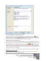
Login
The main FAST screen is shown below (Figure 4). It provides access to all other features of the program,
such as the definition of the briefing project, the creation of design targets and the creation of the design.
Figure 4: FAST main form. Provides access to all other features
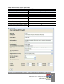
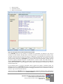
Define facility
This form is used to enter and edit the main characteristics of the facility to be designed and can be
described as the birth certificate of the design. Most of the fields are self-explanatory; however, the
‘Designated Level of Facility’ field needs special mention.
This field is accessible through the 'FACILITY_LEVEL' system variable in the ESPACE rule programming
language. It is especially useful to distinguish or have different rules for different types of hospital. The
'FACILITY_LEVEL' system variable returns the following values (Table 4):
INFRASTRUCTURE UNIT SUPPORT SYSTEMS (IUSS) PROJECT
Health Facility Guides: 10 September 2014
Facility Assembly Schedule Toolkit briefing tool (FAST)
[PROPOSAL V.3]
7
Table 5: Implementation of Facility Level in FAST
Implementation of Health Facility Level in FAST
Type of health facility
Level number accessible through 'FACILITY_LEVEL' system variable
Clinic
Community Health Centre
District Hospital (Level 1)
Outreach Mobile
Regional Hospital (Level 2)
Special Maternity
Special Psychiatric
Special Tropical
Tertiary Hospital (T1) Developing
Tertiary Hospital (T2) Fully Developed
Tertiary Hospital (T3) National Referral Hospital
Tertiary Hospital (T4) Central Referral Hospital
1
2
3
4
5
6
7
8
9
10
11
12
Figure 5: Current Health Facility form that is used to define the main characteristics of the design
INFRASTRUCTURE UNIT SUPPORT SYSTEMS (IUSS) PROJECT
Health Facility Guides: 10 September 2014
Facility Assembly Schedule Toolkit briefing tool (FAST)
[PROPOSAL V.3]
8
Space assembly dashboard (create design menu item)
This is the main form where accommodation schedules are designed. The following methods can be used
to create a design:
•
It can be created room by room from the ROOM DETAIL LIBRARY. (Least efficient)
•
A design can be imported from an external source such as a CAD system through the FAST
comma delimited exchange format documented elsewhere in this document in Appendix B. (Very
efficient)
•
It can be assembled from predefined assemblies from the ASSEMBLY LIBRARY. (Very efficient)
Assembly design from ROOM DETAIL LIBRARY
This is the most fundamental and slowest (from a productivity point of view) design action that FAST
supports. This can be used to achieve the following tasks:
•
A new design assembly can be created from a set of rooms.
•
An existing design can be modified by adding or deleting rooms.
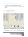
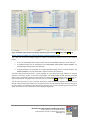
Figure 6: Create a design from ROOM DETAIL LIBRARY (Drag from 1 and Drop at 2 or 3)
Figure 6 illustrates the various possible actions. If a space has a light blue square block indicator in the
ROOM DETAIL LIBRARY between the Space Use and Area (m²) fields, then it means that there is an
illustrative layout drawing attached to the item. You can view this drawing by dragging the Code field
indicated with a 1 (in this case Code AAAD) from the ROOM DETAIL LIBRARY and drop it on the display
drawing action indicated with a 2. This will launch the FAST viewer that will give you an indication of the
design of a particular layout such as the m² area, dimensions and internal layout. (Figure 7)
Once the designer is satisfied with the selection of a particular room type, it can be dragged and dropped
into the DESIGN ASSEMBLY area by dropping the room either on the Class field or the Assembly Code
field.
INFRASTRUCTURE UNIT SUPPORT SYSTEMS (IUSS) PROJECT
Health Facility Guides: 10 September 2014
Facility Assembly Schedule Toolkit briefing tool (FAST)
[PROPOSAL V.3]
9
You will notice that the Dept. and Assembly Code fields contain a ‘-‘ at this stage. This indicates that the
particular space has not yet been allocated to a health facility department, i.e. it is effectively ‘homeless’.
At this stage you can allocate a department or wait until you have all the rooms for a particular
department and then allocate them all. The Assembly Code is at this stage unallocated, because spaces
were dropped in one-by-one from the ROOM DETAIL LIBRARY. A code will be allocated when a particular
set of rooms such as a complete ward design is transferred to the ASSEMBLY LIBRARY and then becomes
a named assembly that can be used in future designs. If a named assembly is brought into the DESIGN
ASSEMBLY AREA, then the Assembly Code and version number are displayed in this field.
If you dragged-and-dropped the wrong space type into the DESIGN ASSEMBLY, you can easily delete it by
executing the action illustrated in Figure 12. Be sure to drag-and-drop from the Class field and not the
Assembly Code field, unless you want to delete an entire assembly.
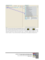
Figure 7: FAST drawing display of room AAAD, a four-bed unit, excluding en suite that is 42.21 m²
Assemble design from ASSEMBLY LIBRARY
This is the most efficient (from a productivity point of view) design action that FAST supports. This can be
used to achieve the following tasks:
•
Large and complex design assemblies can be quickly created from assemblies that, for example,
contain an entire ward.
•
An existing design can be modified by adding or deleting single rooms or entire assemblies due to
the introduction of version numbers in the Assembly Code field.
INFRASTRUCTURE UNIT SUPPORT SYSTEMS (IUSS) PROJECT
Health Facility Guides: 10 September 2014
Facility Assembly Schedule Toolkit briefing tool (FAST)
[PROPOSAL V.3]
10
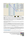
Figure 8: Create a design from the ASSEMBLY LIBRARY (Drag from 1 and Drop at any position 2)
Figure 8 illustrates the various possible actions. Select an existing design assembly from the ASSEMBLY
LIBRARY if there is a suitable one. If an assembly has a light blue square block indicator in the ASSEMBLY
LIBRARY between the Assembly Name and Assembly Description, then it means that there is an
illustrative layout drawing attached to the item. You can view this drawing by dragging the Assembly
Code field indicated with a 1 (in this case Code MED_W_D) from the ASSEMBLY LIBRARY and drop it on
the display drawing action illustrated above in Figure 8. This will launch the FAST viewer that will give you
an indication of the design of a particular layout.
Once the designer is satisfied with the characteristics of a particular assembly type, it can be dragged and
dropped into the DESIGN ASSEMBLY area by dropping the assembly room either on the Class field, or the
Assembly Code field.
You will notice that the Dept. field will contain the department that was originally allocated when the
assembly was built. The Assembly Code fields will contain a ‘MED_W_D/1‘at this stage. This indicates that
after insertion of assembly code ‘MED_W_D’, version number ‘1’ was allocated to it. This is a particularly
useful feature. If you insert another instance of the same assembly version, number ‘2’ will be allocated to
all the spaces that belong to that instance. The fact that new version numbers are allocated makes it very
easy to delete an entire assembly from the DESIGN ASSEMBLY avoiding the tedium of deleting each room
separately.
If you dragged-and-dropped the wrong assembly into the DESIGN ASSEMBLY you can easily delete it by
executing the action illustrated in Figure 9. Be sure to drag-and-drop from the Assembly Code field if you
want to delete an entire instance of an assembly. As before, if you want to delete or add individual spaces
to the assemblies contained in the DESIGN ASSEMBLY, you can easily delete it by executing the action
illustrated in Figure 9. Be sure to drag and drop from the Class field to remove single spaces.
Use of DESIGN COMPARATOR
The FAST DESIGN COMPARATOR is used to compare different designs with regard to sizes, types and
number of spaces. This is useful to compare precedent designs against a new DESIGN ASSEMBLY.
INFRASTRUCTURE UNIT SUPPORT SYSTEMS (IUSS) PROJECT
Health Facility Guides: 10 September 2014
Facility Assembly Schedule Toolkit briefing tool (FAST)
[PROPOSAL V.3]
11
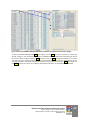
Figure 9: The FAST DESIGN COMPARATOR allows convenient comparison between two designs
To open the DESIGN COMPARATOR Drag from object at 1 and Drop on action at position 2. If there was
already a design in the comparator it will open the DESIGN COMPARATOR panel and display the data. If
you want to display a different design, Drag from action at 3 and Drop on object at position 4. To retrieve
any design from the design repository follow the method illustrated in Figure 9. A list of designs that is
currently available in the design repository will appear in a block with a red border. Drag from object at 5
and Drop on object at position 6. The design selected will now appear in the DESIGN COMPARATOR.
INFRASTRUCTURE UNIT SUPPORT SYSTEMS (IUSS) PROJECT
Health Facility Guides: 10 September 2014
Facility Assembly Schedule Toolkit briefing tool (FAST)
[PROPOSAL V.3]
12
Figure 10: Select a design from the design repository for insertion into the DESIGN COMPARATOR
Create template design target
It is a rather difficult and tedious process to create design targets for health facilities, because a designer
cannot simultaneously think of all aspects that need to be considered in this complex environment. In
recognition of this a special action has been introduced to quickly and accurately build a template target.
Once this has been done the user can modify it to suit the specific requirements of a design.
The first step is to create a design assembly that most closely matches what the design team thinks is the
best solution for a particular size health facility. It could be based on a known existing hospital, if you have
the detail available, or you can build it from assemblies in the ASSEMBLY LIBRARY, or you could even go to
the effort of starting completely from scratch.
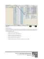
Once you are satisfied with the design in the DESIGN ASSEMBLY you can Drag from position 1 and Drop at
position 2. Behind the scenes a rather complex series of calculations takes place to create a template
target. The number of functional planning units per department, as well as an area range is calculated.
FAST calculates the actual m² per planning unit, per department and then adds 5% above and below this
figure to create a 10% target range. Once this has been done the user can inspect the results and make
finer adjustments where necessary to complete the target.
INFRASTRUCTURE UNIT SUPPORT SYSTEMS (IUSS) PROJECT
Health Facility Guides: 10 September 2014
Facility Assembly Schedule Toolkit briefing tool (FAST)
[PROPOSAL V.3]
13
Figure 11: Create a new functional unit design target from a design assembly. (Drag from 1 and Drop at
position 2)
Delete actions
Due to the large number of rooms that define a large health facility a hierarchy of delete actions has been
introduced in FAST to make the system as efficient as possible. On the space assembly dashboard, six
possible delete actions exist:
•
Delete a specific room (Figure 12)
•
Delete specific design assembly (Figure 13)
•
Delete entire design assembly (Figure 14)
•
Delete (hide) design comparator (Figure 15)
•
Delete assembly library item (Figure 16)
•
Delete the entire project from the design repository (Figure 17 and 18).
INFRASTRUCTURE UNIT SUPPORT SYSTEMS (IUSS) PROJECT
Health Facility Guides: 10 September 2014
Facility Assembly Schedule Toolkit briefing tool (FAST)
[PROPOSAL V.3]
14
Figure 12: Delete a specific room from the DESIGN ASSEMBLY (Step 1 and 2) (Drag from 1 and Drop at
2)
Figure 13: Delete specific design assembly (Step 1 and 2) (Drag from 1 and Drop at 2)
INFRASTRUCTURE UNIT SUPPORT SYSTEMS (IUSS) PROJECT
Health Facility Guides: 10 September 2014
Facility Assembly Schedule Toolkit briefing tool (FAST)
[PROPOSAL V.3]
15
Figure 14: Delete entire design assembly (Step 1 and 2) (Drag from 1 and Drop at 2)
Figure 15: Delete design comparator (Step 1 and 2) (Drag from 1 and Drop at 2)
INFRASTRUCTURE UNIT SUPPORT SYSTEMS (IUSS) PROJECT
Health Facility Guides: 10 September 2014
Facility Assembly Schedule Toolkit briefing tool (FAST)
[PROPOSAL V.3]
16
Figure 16: Delete assembly library item (Step 1 and 2) (Drag from 1 and Drop at 2)
Figure 17: Delete entire project permanently from the design repository (Step 1 and 2) (Drag from 1 and
Drop at 2)
INFRASTRUCTURE UNIT SUPPORT SYSTEMS (IUSS) PROJECT
Health Facility Guides: 10 September 2014
Facility Assembly Schedule Toolkit briefing tool (FAST)
[PROPOSAL V.3]
17
Figure 18: Delete entire project from design repository (Step 3 and 4) (Drag from 3 and Drop at 4)
Space target dashboard (define design targets menu item)
This is the main form where design targets are created. The following methods can be used to create a
target:
•
It can be created department by department from the FUNCTIONAL UNIT LIST. (Least efficient)
•
A predefined target can be selected from the FUNCTIONAL UNIT DESIGN TARGET LIBRARY, if a
suitable target already exists. (Very efficient)
•
A target template can be created from a good precedent design that is currently loaded in the
DESIGN ASSEMBLY. This was illustrated in Figure 11 above. (Very efficient)
The latter method discussed above is a good example of a case-based reasoning approach to complex
problems. The theory of CBR, as well as the advantages and disadvantages of CBR, has been discussed
above. Figure 19 illustrates phase 1 of the creation of a design target for a medical ward. To achieve this,
select the functional unit (department) that you want to work with. Drag from object 1 and Drop at 2.
You will notice that only one line is inserted, because the FUNCTIONAL UNIT DESIGN TARGET panel is by
default in Only Planning Unit mode. You can expand the list into individual functional units by clicking on
the radio button. The heading will turn blue and confirm that you are now in Planning and Functional Unit
mode. Instead of 11 only one item will now be displayed (Figure 19).
INFRASTRUCTURE UNIT SUPPORT SYSTEMS (IUSS) PROJECT
Health Facility Guides: 10 September 2014
Facility Assembly Schedule Toolkit briefing tool (FAST)
[PROPOSAL V.3]
18
Figure 19: Create design target from FUNCTIONAL UNIT LIST phase 1 (Drag from 1 and Drop at 2)
Figure 20 illustrates how an expanded list for the medical departments looks. One department expanded
into 11 sub-items called functional units. Each functional unit represents a different planning unit. Each
department should have at least four functional units, i.e. workspace, workspace support, core, and
structure. However, in many cases there will be more depending on the complexity of the department.
INFRASTRUCTURE UNIT SUPPORT SYSTEMS (IUSS) PROJECT
Health Facility Guides: 10 September 2014
Facility Assembly Schedule Toolkit briefing tool (FAST)
[PROPOSAL V.3]
19
Figure 20: Create design target from FUNCTIONAL UNIT LIST phase 2
You can now proceed to fill in the No. of FPUs, Min. Area (m²) and the Max Area (m²) fields. This is a timeconsuming process and requires a very high level of skill to accomplish. It is assumed that an indication of
the number of planning and functional units would be available from the output of the infrastructure
optimisation planning toolkit (IOPT).
Once specific targets have been set, you may save the target for future use. Two possibilities are
supported. You can Drag from 2 (FUNCTIONAL UNIT DESIGN TARGET) and Drop at 3, or you can Drag
from 2 (FUNCTIONAL UNIT DESIGN TARGET Class object) and Drop at 3. The former will transfer or save
the complete contents of the FUNCTIONAL UNIT DESIGN TARGET into the FUNCTIONAL UNIT DESIGN
TARGET LIBRARY and the latter will only transfer the specific department where you start the Drag from.
This provides the designer with a lot of flexibility.
Note that a default name is allocated to the design target when it arrives in the FUNCTIONAL UNIT
DESIGN TARGET LIBRARY. The Assembly Code = ‘-‘, the Assembly Name = ‘New Functional Unit Target
Assembly’ and the Assembly Description is ‘This is a new Functional Unit Target assembly.’ These general
default descriptions need to be renamed to something that precisely describes the intent and
characteristics of the particular design target.
INFRASTRUCTURE UNIT SUPPORT SYSTEMS (IUSS) PROJECT
Health Facility Guides: 10 September 2014
Facility Assembly Schedule Toolkit briefing tool (FAST)
[PROPOSAL V.3]
20
THE ESPACE PARAMETRIC RULE DEFINITION AND AD HOC SPATIAL
ANALYSIS LANGUAGE
Introduction
This section is a specialized section about the ESPACE language. It would normally only be used by
advanced or interested users. It is included here to provide full documentation of all the capabilities of
FAST.
The ESPACE rule and ad hoc query definition language is a simple (not as extensive as Java, C or Visual
1
Basic .NET) and flexible interpretive language that is used as part of the FAST system to analyse spatial
usage directly and to formulate rules to derive the area of spaces that vary their size, depending on a
specific context. It can be used to compare a particular facility against any number of norms, or even
other facilities.
For the development of ESPACE applets a special interactive code developer is provided that can be used
to create ad hoc requests and/or to develop code that will be used in the norms formulation. (Figure 21)
In terms of ESPACE a rule or ad hoc query applet is an autonomous, limited size code fragment that can be
used to formulate ad hoc spatial queries or it can be used in the norms rule formulation itself.
1
The ESPACE rule is executed line-by-line when the Execute button is pressed in the Interactive Query
Builder/Debugger or when a derived space is dragged-and-dropped into the DESIGN ASSEMBLY area of FAST.
INFRASTRUCTURE UNIT SUPPORT SYSTEMS (IUSS) PROJECT
Health Facility Guides: 10 September 2014
Facility Assembly Schedule Toolkit briefing tool (FAST)
[PROPOSAL V.3]
21
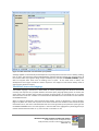
Figure 21: FAST interactive rule and ad hoc query builder
Although applets can theoretically be developed for any facility hierarchical level such as facility, building,
floor or space, the interactive Query Builder/Debugger supports testing of applets only at facility level. At
the moment FAST only supports design analysis at facility level, because the DESIGN ASSEMBLY system
does not support other levels such as building, floor or space. As the need arises in future, the
development team might consider the further expansion and support of hierarchical facility levels to
support more advanced analysis.
The ESPACE interactive language
The ESPACE language is described in detail below. It contains powerful high level functions that would
normally have required very complex database structured query language (SQL) queries to achieve the
same result. It also contains logical control structures normally found in any language such as an If Then
Else End control structures. Variables are created with the DECLARE function and results are returned with
the RETURN function.
When an applet is developed in the Interactive Query Builder, results are displayed in a pop-up window.
(Figure 22) When the same code is placed in the Area Calculation Rule textbox of the Functional Space
Classification form, the code is executed whenever the user drag-and-drop the particular space type into
the DESIGN ASSEMBLY area. The result appears in the area field and is highlighted in yellow (Figure 23) to
indicate that the derived answer in m² is the result of a calculation or rule.
INFRASTRUCTURE UNIT SUPPORT SYSTEMS (IUSS) PROJECT
Health Facility Guides: 10 September 2014
Facility Assembly Schedule Toolkit briefing tool (FAST)
[PROPOSAL V.3]
22
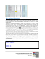
If no applets have been defined for a particular classification category or space type, then the Area m² will
not be filled in automatically. If no formula has been defined for a space type and no static area has been
allocated then nothing will be displayed.
Figure 22: Result of query in interactive environment
INFRASTRUCTURE UNIT SUPPORT SYSTEMS (IUSS) PROJECT
Health Facility Guides: 10 September 2014
Facility Assembly Schedule Toolkit briefing tool (FAST)
[PROPOSAL V.3]
23
Figure 23: The yellow highlighted block indicates that the area in m² is the result of a resolved rule
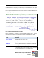
How to develop an ESPACE applet
The discussion below describes how to develop an ESPACE applet. Although FAST is delivered with a fully
functional set of ESPACE applets, it might be necessary from time to time to modify the existing norms or
to create ad hoc queries for particular purposes. Please refer to Table 5 for a summary of all available
ESPACE functions.
Assume that an applet needs to be developed that will return the percentage of core area in a health
facility. Assume that the designer aims to achieve a % somewhere between 32.51% and 35.94%. The
current Khayelitsha Hospital has a core percentage of 34.23%. To activate the FAST Interactive Query
Builder/Debugger, select the FAST Rule Builder option on the Rule Definition tab of the FAST Main Form.
Create a new applet record by selecting the
action button on the form. Choose an appropriate name
for the applet and enter it in the Program Name field. Enter an appropriate description for the applet such
as “This applet returns the percentage of core area. In this case we are aiming for something that should
be between 32.51% and 35.94%” to describe the exact purpose or function of the applet.
The next field can be left open at this stage because the applet must first be developed before a specific
department can be selected for testing and more specific analysis purposes.
The purpose of the applet is to return the percentage of core area. ESPACE has a high level function CORE
that will return all spaces that have a top level classification category of C. Seeing the percentage core in
relation to the workspace area, the applet calculates the actual workspace area. In the ESPACE functional
space classification, category A contains categories that are closely related to, but are not actually
workspace area. The solution to this is to use the high level WORK_SPACE function and to subtract the
spatial types that must not be included. The first step is therefore to declare temporary variables to
contain these values.
STEP 1: Declare applet variables
DECLARE a = 'WORK_SPACE'
DECLARE c = 'CORE'
DECLARE e = '~AB'
DECLARE f = '~AC'
DECLARE g = '~AD'
INFRASTRUCTURE UNIT SUPPORT SYSTEMS (IUSS) PROJECT
Health Facility Guides: 10 September 2014
Facility Assembly Schedule Toolkit briefing tool (FAST)
[PROPOSAL V.3]
24
STEP 2: Calculate percentage core space
RETURN c/(a - (e+f+g)) * 100.0
The RETURN statement will display the result of the calculation. This is useful in the interactive debugging
and testing environment. However, when the applet is placed in the norms definition environment, this
program statement can be disabled by placing a // in front of the statement. The statement will then look
like this:
// RETURN c/(a - (e+f+g)) * 100.0
Core is calculated by dividing the amount of core area (contained in variable c) by the amount of
workspace area (contained in variable a). The amount of workspace area is adjusted by subtracting all
shared/communal (~AB), public interface (~AC) and technical/special (~AD) areas. Note the use of the ‘~’.
This indicates that all spatial type categories lower down in the hierarchy, including the actual
classification category, must be included. This is a convenient shorthand method in the case of ~AB to
include AB, ABA, ABB, ABC, ABD, ABE, ABF and ABG. If you want just one particular category and nothing
else, use the _AB notation.
STEP 3: Calculate result to be returned
IF c/(a - (e+f+g)) * 100.0 > 35.94 THEN
RETURN '> 35.94%'
ELSE
RETURN '< 35.94%'
END
The applet is now complete and can be tested. Before the applet is tested make sure that the DESIGN
ASSEMBLY area of the Create Design (Space ASSEMBLY DASHBOARD) contains some realistic data, facility,
assembly or set of desired spaces. Select the Parse button to check the code and run the applet. If there
was a logical error in the code, then this will be reported in the Log field, for example:
SYNTAX ERROR. Line 14. Expecting: EOF - & ) * / + < <= <> == > >= declare do else end if read return then
while
If no errors were found then the log will report
-- Applet Valid –
You can now proceed and analyse other facilities. This particular example can only be used in the
interactive environment, because it does not return an area. If you formulate a rule for use in DESIGN
ASSEMBLY area, the applet must be rule that returns an area. Furthermore, it must only return one result,
because the area field can only contain one answer.
INFRASTRUCTURE UNIT SUPPORT SYSTEMS (IUSS) PROJECT
Health Facility Guides: 10 September 2014
Facility Assembly Schedule Toolkit briefing tool (FAST)
[PROPOSAL V.3]
25
Table 6: Summary of ESPACE functions
Special ESPACE functions
ESPACE function
Examples
Comments
FACILITY_LEVEL
Hierarchical
2
level
1 = facility
2 = building
3 = floor
4 = space
1
DECLARE d = 'FACILITY_LEVEL'
FLOORS
1, 2
DECLARE a = 'FLOORS'
Returns the level of
the particular health
facility as defined in
the ‘Designated
Level of Facility’ field
of the Current Health
Facility form.
At level 1 it returns
all floors in the
facility. At level 2 it
returns only the
floors within the
current building.
Returns the number
of persons in the
entire facility.
Returns the total
number of persons
at the current
hierarchical level.
Returns the number
of persons in a
specific classification
category or
classification
hierarchy.
RETURN a
ALL_PERSONS
1
DECLARE a = 'ALL_PERSONS'
PERSONS
1, 2, 3 or 4
RETURN a
DECLARE a = ‘PERSONS’
RETURN a
PERSONS(_A to _DE or ~A to
~DE)
WORK_SPACE
1, 2, 3 or 4
1
DECLARE a = 'ALL_PERSONS'
DECLARE b = 'PERSONS(~AAA)'
DECLARE c = 'PERSONS(~AAB)'
DECLARE d = 'PERSONS(~AAD)'
DECLARE e = 'PERSONS(~AAD)'
RETURN a
RETURN b
RETURN c
RETURN d
RETURN e
// Total amount of workspace area per
person
DECLARE a = 'ALL_PERSONS'
DECLARE b = 'WORK_SPACE'
DECLARE c = 'WORK_SPACE_SUPPORT'
DECLARE d = 'CORE'
DECLARE e = 'STRUCTURE'
Returns all the
workspace (category
A) space in the entire
facility.
DECLARE f = b+c+d+e
RETURN 'Category Workspace (A) = '
RETURN b
2
In the FAST software environment only one hierarchical level is supported, because the concept of
building, floor and space does not exist. The only level supported is Facility Level.
INFRASTRUCTURE UNIT SUPPORT SYSTEMS (IUSS) PROJECT
Health Facility Guides: 10 September 2014
Facility Assembly Schedule Toolkit briefing tool (FAST)
[PROPOSAL V.3]
26
RETURN 'Category Workspace Support (B) =
'
RETURN c
RETURN 'Category Core (C) = '
RETURN d
RETURN 'Category Structure (D) = '
RETURN e
RETURN 'Number of Persons = '
RETURN a
RETURN 'Total Floor Area = '
RETURN f
WORK_SPACE_SUPPORT
1
CORE
1
RETURN 'Space per Person = '
RETURN f/a
See above
See above
Returns all the
workspace support
(category B) space in
the entire facility.
Returns all the core
(category C) space in
the entire facility.
STRUCTURE
1
See above
Returns the
structural area
(category D) for the
entire facility. It
includes both
external and internal
walls.
BEDS
1
DECLARE a = ‘BEDS’
Returns the total
number of beds in
the facility. The
PeopleCodes field
value of ‘M001’ in
the
<Space_ASSEMBLY>
table is used to
recognise beds.
RETURN ‘Total number of beds = ‘ & & a
FACILITY_LEVEL
1
// Calculate CAAG
DECLARE a = '@?'
DECLARE b =
'AREA_DEPARTMENT_SPACETYPE(?,CAAG)'
DECLARE c =
'AREA_DEPARTMENT_SPACETYPE(?,D)'
DECLARE d = 'FACILITY_LEVEL'
IF (d >= 3) THEN
RETURN (a-b-c)*0.28829690
ELSE
RETURN (a-b-c)*0.28829690
END
See above
INFRASTRUCTURE UNIT SUPPORT SYSTEMS (IUSS) PROJECT
Health Facility Guides: 10 September 2014
Facility Assembly Schedule Toolkit briefing tool (FAST)
[PROPOSAL V.3]
Returns the level of
the facility as a
whole number
(integer) selected on
the Define Facility
form. The values
returned are
described in detail in
Table 6. The function
reads the
TypeOfHealthFacility
field of the
<CurrentFacility>
database table.
Returns the sum of
the area for only the
27
_A to _DE
1, 2, 3 or 4
~A to ~DE
1, 2, 3 or 4
See above
Returns the sum of
the area for the
hierarchical family of
space classifications
where the particular
classification is at the
top of the hierarchy.
The required
classification family
must be prefixed
with a ‘~’ to indicate
to the ESPACE
interpreter that a
space category
rather than a
variable is intended.
@A to @J
1
DECLARE a = '@BAD'
DECLARE b = '@?'
Returns the sum of
the area for only the
specific department
classification. The
classification must
be prefixed with a
‘@’ to indicate to the
ESPACE interpreter
that a department
category rather than
a variable is
intended.
specific
classification. The
classification must
be prefixed with a ‘_’
to indicate to the
ESPACE interpreter
that a space category
rather than a
variable is intended.
RETURN 'Area for only department BAD = '
&a
RETURN 'Area for any department with late
binding = ' & b
#A to #J
1
DECLARE a = '#BAD'
DECLARE b = '#?'
RETURN 'Area for hierarchy under BAD = ' &
a
RETURN 'Area for hierarchy under BAD with
late binding = ' & b
?
Returns the sum of
the area for the
hierarchical family of
department
classifications where
the particular
classification is at the
top of the hierarchy.
The required
classification family
must be prefixed
with a ‘#’ to indicate
to the ESPACE
interpreter that a
space category
rather than a
variable is intended.
This is the late
binding symbol used
for department/functional unit
1
INFRASTRUCTURE UNIT SUPPORT SYSTEMS (IUSS) PROJECT
Health Facility Guides: 10 September 2014
Facility Assembly Schedule Toolkit briefing tool (FAST)
[PROPOSAL V.3]
28
specifically. This
means that the
relevant department
is only provided at
runtime when the
particular
department is
known within the
specific context. This
is very economical,
because only one
applet can be
developed and used
universally.
General ESPACE functions
Comment Start = '/*'
Comment End = '*/'
Comment Line = '//'
n/a
// Development and debug code
Provides a means to
comment parts of
the applet.
DECLARE
n/a
DECLARE a = 12
DECLARE b = 'ALL_PERSONS'
DECLARE c = 'PERSONS(~AAC)'
DECLARE d = '_AAC'
Creates new
variables. The first
character must be
alphabetic. Different
declarations are
possible depending
on the desired
result. The variables
are case-insensitive
and the length is
virtually unlimited.
Practical
considerations will
however limit it to
no more than 10
alphanumeric
characters.
RETURN
n/a
IF f/a > 12 THEN
RETURN '>'
ELSE
RETURN '<'
END
Returns the result of
an evaluation. If the
first character
returned is a ‘<’ or
‘>’ then the answer
will be coloured
green or red.
If Then End
If Then Else End
n/a
Provides logical
control in the applet.
While Do End
n/a
IF f/a > 12 THEN
RETURN '>'
ELSE
RETURN '<'
END
DECLARE a = 12
WHILE (a > 1) DO
DECLARE a = a -1
RETURN a
END
INFRASTRUCTURE UNIT SUPPORT SYSTEMS (IUSS) PROJECT
Health Facility Guides: 10 September 2014
Facility Assembly Schedule Toolkit briefing tool (FAST)
[PROPOSAL V.3]
Provides an
alternative to the If
Then End or If Then
Else End structure.
Note the use of the
RETURN to
decrement the value
being tested for.
29
+, -, *, /
n/a
IF (a/12)+(3.14*2) > 24 then
RETURN ‘>’
ELSE
RETURN ‘<’
END
Plus, minus, multiply
and divide can be
used in any
expression with or
without nesting
brackets.
&
n/a
RETURN ((a/b) * 100) & ' %'
This is useful to
concatenate strings
or to append special
symbols to an
answer. Enclose the
numerical part
between braces;
otherwise
unexpected results
may be produced.
<, <=, >=, ==, <>
n/a
If (a >= 12) THEN
RETURN ‘larger or equal 12’
END
These operators are
available for
comparisons.
Example of an ESPACE applet
To develop a new ESPACE applet or edit an existing one, go to the ESPACE Interactive Query
Builder/Debugger. Access to this utility is found on the Rule Definition tab of the FAST Main Menu (Figure
4).
INFRASTRUCTURE UNIT SUPPORT SYSTEMS (IUSS) PROJECT
Health Facility Guides: 10 September 2014
Facility Assembly Schedule Toolkit briefing tool (FAST)
[PROPOSAL V.3]
30
Figure 24: ESPACE applet to calculate department areas
Press the button to open the Interactive Query Builder. To create new applets select the
button at
the bottom of the form. Fill in an appropriate name in the Program Name field. This name should describe
what the applet does, for example DEPARTMENT AREA. The description field offers the opportunity to
describe in a little bit more detail what the purpose of the applet is for example
This applet returns the total department area
The current contents (list of spaces) of the DESIGN ASSEMBLY are used during debugging to run the code.
(Figure 24) Before an applet can be fully tested, select a current department from the dropdown list in the
interactive debugger. To test an applet for valid syntax, press the
button. If the test is
successful then the words -- Applet Valid – will be displayed in the Debugging Log field. If the user failed
3
to select a particular department beforehand, then the late binding symbol ‘?’ will be undefined. This
means that the applet is valid; however it cannot return any values, because it does not know for which
department you want to run the applet for.
An ESPACE rule or ad hoc query consists of three main sections and is created in the applet section (Figure
25):
3
Late binding means a value is only known at a late stage, i.e. when the code executes. This makes the
applet very flexible, because it can be used in any context.
INFRASTRUCTURE UNIT SUPPORT SYSTEMS (IUSS) PROJECT
Health Facility Guides: 10 September 2014
Facility Assembly Schedule Toolkit briefing tool (FAST)
[PROPOSAL V.3]
31
1.
2.
3.
Declare section
Calculation section
Return or result section
Figure 25: The applet section of the Interactive Query Builder
In the DECLARE section all the variables to accomplish the calculations are defined. In this case six
variables have been defined. Although there is virtually no limitation to the length of the variable names,
it should not be too long. For ease of use there is no difference in the declaration for numerical or text
variables. For this reason users should use variables in a sensible descriptive way. For example, one should
not try and add a string such as ‘Workspace’ to a numeric value such as 5 and expect a realistic result. If
you want to display a friendly description concatenated to a numeric answer use the & operator, for
example ‘Workspace Support = ‘ & b. It is good style to use braces around variables such as d/e. This
ensures that a calculation is bound together correctly, before attempting to concatenate the result to
some descriptive text.
In the example there is no formal calculation section, because the applet is relatively simple. For
debugging purposes some RETURN statements can be included to progressively check the correctness of
the applet. Once the applet is properly tested the debugging statements can be commented out with ‘/*’
and ‘*/’ or ‘//’ on each comment code line.
The final section is the RETURN section where the results of the applet are displayed. If the applet will be
used in the rule-based environment in the DESIGN ASSEMBLY area then only one result must be returned,
INFRASTRUCTURE UNIT SUPPORT SYSTEMS (IUSS) PROJECT
Health Facility Guides: 10 September 2014
Facility Assembly Schedule Toolkit briefing tool (FAST)
[PROPOSAL V.3]
32
because the area field can obviously only contain on value at a time. If the applet will only be used in the
interactive environment for analysis or enquiry purposes, then multiple results can be returned to analyse
the spatial characteristics. In the example the final output of the results are displayed with six RETURN
statements.
ESPACE knows in which execution mode it is running, i.e. interactive mode (debugging or ad hoc query) or
rule interpretation mode in the DESIGN ASSEMBLY area. In the interactive applet development
environment, output is displayed in a small pop-up window. When a user drags and drops a space with a
rule attached to it into the FAST DESIGN ASSEMBLY area, the results are returned in the area field of the
DESIGN ASSEMBLY section of the Create Design form. It is highlighted in yellow to indicate that the result
is based on an ESPACE formula.
INFRASTRUCTURE UNIT SUPPORT SYSTEMS (IUSS) PROJECT
Health Facility Guides: 10 September 2014
Facility Assembly Schedule Toolkit briefing tool (FAST)
[PROPOSAL V.3]
33
APPENDIX A – FORMAL ESPACE LANGUAGE SPECIFICATION
Below is the formal Backus-Naur syntax specification or logical description of the ESPACE ad hoc query
and rule definition language used in FAST. The ESPACE language implementation for the IUSS project was
developed by means of the GOLD (Grammar Oriented Language Developer) Parser Builder version 5.2.0,
written by Devin Cook. (Cook, 1997)
"Name" = 'ESPACE'
"Author" = 'D.C.U. Conradie'
"Version" = '1.0'
"About" = 'ESPACE is designed to handle parametric space planning analysis and norms'
"Case Sensitive" = False
"Start Symbol" = <Statements>
{String Ch 1} = {Printable} - ['']
{String Ch 2} = {Printable} - ["]
{ID Tail} = {Alphanumeric} + [_]
Id
= {Letter}{Alphanumeric}*
! String allows either single or double quotes
StringLiteral = '' {String Ch 1}* ''
| '"' {String Ch 2}* '"'
NumberLiteral = {Digit}+('.'{Digit}+)?
Comment Start = '/*'
Comment End = '*/'
Comment Line = '//'
<Statements> ::= <Statement> <Statements>
| <Statement>
<Statement> ::= return <Expression>
| return <Expression> read ID
| declare ID '=' <Expression>
| while <Expression> do <Statements> end
| if <Expression> then <Statements> end
| if <Expression> then <Statements> else <Statements> end
<Expression> ::= <Expression> '>' <Add Exp>
| <Expression> '<' <Add Exp>
| <Expression> '<=' <Add Exp>
| <Expression> '>=' <Add Exp>
| <Expression> '==' <Add Exp>
| <Expression> '<>' <Add Exp>
| <Add Exp>
<Add Exp> ::= <Add Exp> '+' <Mult Exp>
| <Add Exp> '-' <Mult Exp>
| <Add Exp> '&' <Mult Exp>
INFRASTRUCTURE UNIT SUPPORT SYSTEMS (IUSS) PROJECT
Health Facility Guides: 10 September 2014
Facility Assembly Schedule Toolkit briefing tool (FAST)
[PROPOSAL V.3]
34
| <Mult Exp>
<Mult Exp> ::= <Mult Exp> '*' <Negate Exp>
| <Mult Exp> '/' <Negate Exp>
| <Negate Exp>
<Negate Exp> ::= '-' <Value>
| <Value>
<Value>
::= ID
| StringLiteral
| NumberLiteral
| '(' <Expression> ')'
INFRASTRUCTURE UNIT SUPPORT SYSTEMS (IUSS) PROJECT
Health Facility Guides: 10 September 2014
Facility Assembly Schedule Toolkit briefing tool (FAST)
[PROPOSAL V.3]
35
APPENDIX B - INTERFACING TO OTHER SYSTEMS
FAST does not exist on its own and therefore needs a method to import information from other systems,
such as external CAD-systems, Quantity Surveyor software, CodeBook and spreadsheets. This appendix
describes the simple comma delimited flat file structure that facilitates this.
Figure 26 illustrates the required structured fields to export information into FAST from CAD-systems such
as AutoCAD, Revit and CADDIE. A record in this standard will contain either six or seven comma delimited
fields, depending on the type of record. Table 6 illustrates how the comma delimited file for a small clinic
looks that conforms to the structure illustrated in Figure 26.
Figure 26: The FAST comma delimited interface standard
Table 6 provides detail about the FAST comma delimited exchange standard fields. Please note that the
fields are separated with a ‘,’ and if there is no person type field, the last field ends with a ‘,’. The various
parts of the hierarchical structure for the hierarchical location are concatenated with the ‘:’ symbol.
Table 7: The FAST comma delimited exchange format
Field
Description
Friendly Description
Short description of the particular room.
Facility Code
A facility code. One facility can contain many buildings, floors and
spaces.
Building Code
A building code. The building code is separated from the facility code
with a ‘:’ separator. This is the second level in the facility hierarchy. A
facility might contain one or many buildings.
Floor Code
A floor code. The floor code is separated from the building code with a
‘:’ separator. This is the third level of the facility hierarchy. One building
can contain one or many floors in a high-rise health facility.
INFRASTRUCTURE UNIT SUPPORT SYSTEMS (IUSS) PROJECT
Health Facility Guides: 10 September 2014
Facility Assembly Schedule Toolkit briefing tool (FAST)
[PROPOSAL V.3]
36
Field
Description
Space Code
A space code. The space code is separated from the floor code with a ‘:’
separator. This code is selected from the IUSS Functional Space
Classification, e.g. AAAD.
Area in m²
This is the net area in m² of the facility. It should be to 3-decimal
accuracy to ensure adequate accuracy.
Department Code
The department code must be selected from the IUSS Department
Classification.
Sub-Department Code
The sub-department code gives an indication of how contiguous the
spaces in a department are. If all the spaces that make up a
department are together, then all the spaces would have a subdepartment code of A. However, if the department is fragmented in
three main areas, then area 1 would be indicated with a ‘A’, area 2 with
a ‘B’ and area 3 with a ‘C’.
Person Type and Number
This field should only be used for clinical rooms that have a bed unit. It
should not be used for treatment and consulting rooms that might also
contain a bed. The code for a patient is ‘M001’. This is followed by the
‘/’ delimiter and the number of beds in a bed unit, for example 4.
Table 8: Example of a FAST comma delimited file that contains all the spaces for a small clinic
Garden Store,C1:B1:F0:R001,BGK,3.77,AA,A,
Dirty Utility,C1:B1:F0:R002,BMC,5.92,AA,A,
WC Staff,C1:B1:F0:R003,BEC,2.98,AA,A,
WC Staff,C1:B1:F0:R004,BEC,1.8,AA,A,
Kitchen Staff,C1:B1:F0:R005,BQ,9.95,AA,A,
Sub-Waiting Area,C1:B1:F0:R006,CAAK,26.74,AA,A,
Entrance Lobby,C1:B1:F0:R007,CAAM,11.73,AA,A,
Waiting Area,C1:B1:F0:R008,CAAK,31.36,AA,A,
Toilet Lobby,C1:B1:F0:R009,CAAM,5.62,AA,A,
Male Toilets,C1:B1:F0:R010,BEAA,2,AA,A,
Male Toilets,C1:B1:F0:R011,BEAA,9.02,AA,A,
Disabled Toilet,C1:B1:F0:R012,BE,4.22,AA,A,
Female Toilets,C1:B1:F0:R013,BEAB,2,AA,A,
Female Toilets,C1:B1:F0:R014,BEAB,2,AA,A,
Female Toilets,C1:B1:F0:R015,BEAB,7.34,AA,A,
Waiting Area External,C1:B1:F0:R016,CAAK,21.41,AA,A,
Reception,C1:B1:F0:R017,BAA,4.44,AA,A,
Play Area,C1:B1:F0:R018,ALG,7.13,AA,A,
Walk-In C.B.D,C1:B1:F0:R019,BGB,5.17,AA,A,
Room Treatment,C1:B1:F0:R020,AJA,15.26,AA,A,
Room 1 Consulting,C1:B1:F0:R021,AFA,15.26,AA,A,
Room 2 Consulting,C1:B1:F0:R022,AFA,15.26,AA,A,
Home Based Care,C1:B1:F0:R023,AHA,15.26,AA,A,
Passage,C1:B1:F0:R024,CAAB,32.84,AA,A,
Counselling Room,C1:B1:F0:R025,AGA,15.42,AA,A,
Room Triage/Observation,C1:B1:F0:R026,AAJ,12.53,AA,A,
Paraplegic WC,C1:B1:F0:R027,BE,3.24,AA,A,
INFRASTRUCTURE UNIT SUPPORT SYSTEMS (IUSS) PROJECT
Health Facility Guides: 10 September 2014
Facility Assembly Schedule Toolkit briefing tool (FAST)
[PROPOSAL V.3]
37
Medicine Store,C1:B1:F0:R028,BP,8.32,AA,A,
Private Consult,C1:B1:F0:R029,AFA,4.92,AA,A,
Area Medicine Waiting,C1:B1:F0:R030,CAAK,10.2,AA,A,
Dispensary,C1:B1:F0:R031,BP,19.47,AA,A,
Scheduled Medicine Store,C1:B1:F0:R032,BP,4.4,AA,A,
Receiving/Holding,C1:B1:F0:R033,BPG,5.23,AA,A,
Food Parcels Store,C1:B1:F0:R034,BQR,5,AA,A,
Passage,C1:B1:F0:R036,CAAB,12.49,AA,A,
Structure,C1:B1:F0:R037,DA,471.52,I,A,
If the FAST comma delimited exchange file conforms to the standards above, you can import it directly
into the FAST ASSEMBLY LIBRARY by going to the System Administration tab of the FAST Main Form.
Select the Import .txt, .dat or.csv file File Into FAST option. The screen illustrated below in Figure 27
appears.
Figure 27: Select a FAST comma delimited import file
Choose an appropriate file extension with the dropdown indicated as ‘Files of type’. Three types of
extension are supported, i.e. .txt, .dat and .csv. Navigate to the directory where the input file is located.
The screen illustrated with Figure 28 appears.
INFRASTRUCTURE UNIT SUPPORT SYSTEMS (IUSS) PROJECT
Health Facility Guides: 10 September 2014
Facility Assembly Schedule Toolkit briefing tool (FAST)
[PROPOSAL V.3]
38
Figure 28: Select a comma delimited file with a .txt extension
In the example two files are displayed. Select the Clinic_Example.txt file and select the Open command
button. The screen illustrated in Figure 29 appears. Select OK to continue the import. The data is imported
into the ASSEMBLY LIBRARY. After import you can rename the Assembly Code, Assembly Name and
Assembly Description fields to suit your particular description and naming conventions.
Figure 29: Confirm import of FAST comma delimited import file
INFRASTRUCTURE UNIT SUPPORT SYSTEMS (IUSS) PROJECT
Health Facility Guides: 10 September 2014
Facility Assembly Schedule Toolkit briefing tool (FAST)
[PROPOSAL V.3]
39
APPENDIX C – FUNCTIONAL SPACE CLASSIFICATION
INFRASTRUCTUREUNITSUPPORTSYSTEMS(IUSS)PROJECT
Health Facility Guides: 3 March 2014
Facility Assembly Schedule Toolkit briefing tool (FAST)
[DISCUSSION DRAFT 1.0]
40
INFRASTRUCTUREUNITSUPPORTSYSTEMS(IUSS)PROJECT
Health Facility Guides: 3 March 2014
Facility Assembly Schedule Toolkit briefing tool (FAST)
[DISCUSSION DRAFT 1.0]
41
INFRASTRUCTUREUNITSUPPORTSYSTEMS(IUSS)PROJECT
Health Facility Guides: 3 March 2014
Facility Assembly Schedule Toolkit briefing tool (FAST)
[DISCUSSION DRAFT 1.0]
42
INFRASTRUCTUREUNITSUPPORTSYSTEMS(IUSS)PROJECT
Health Facility Guides: 3 March 2014
Facility Assembly Schedule Toolkit briefing tool (FAST)
[DISCUSSION DRAFT 1.0]
43
INFRASTRUCTUREUNITSUPPORTSYSTEMS(IUSS)PROJECT
Health Facility Guides: 3 March 2014
Facility Assembly Schedule Toolkit briefing tool (FAST)
[DISCUSSION DRAFT 1.0]
44
INFRASTRUCTUREUNITSUPPORTSYSTEMS(IUSS)PROJECT
Health Facility Guides: 3 March 2014
Facility Assembly Schedule Toolkit briefing tool (FAST)
[DISCUSSION DRAFT 1.0]
45
INFRASTRUCTUREUNITSUPPORTSYSTEMS(IUSS)PROJECT
Health Facility Guides: 3 March 2014
Facility Assembly Schedule Toolkit briefing tool (FAST)
[DISCUSSION DRAFT 1.0]
46
INFRASTRUCTUREUNITSUPPORTSYSTEMS(IUSS)PROJECT
Health Facility Guides: 3 March 2014
Facility Assembly Schedule Toolkit briefing tool (FAST)
[DISCUSSION DRAFT 1.0]
47
INFRASTRUCTUREUNITSUPPORTSYSTEMS(IUSS)PROJECT
Health Facility Guides: 3 March 2014
Facility Assembly Schedule Toolkit briefing tool (FAST)
[DISCUSSION DRAFT 1.0]
48
INFRASTRUCTUREUNITSUPPORTSYSTEMS(IUSS)PROJECT
Health Facility Guides: 3 March 2014
Facility Assembly Schedule Toolkit briefing tool (FAST)
[DISCUSSION DRAFT 1.0]
49
INFRASTRUCTUREUNITSUPPORTSYSTEMS(IUSS)PROJECT
Health Facility Guides: 3 March 2014
Facility Assembly Schedule Toolkit briefing tool (FAST)
[DISCUSSION DRAFT 1.0]
50
INFRASTRUCTUREUNITSUPPORTSYSTEMS(IUSS)PROJECT
Health Facility Guides: 3 March 2014
Facility Assembly Schedule Toolkit briefing tool (FAST)
[DISCUSSION DRAFT 1.0]
51
INFRASTRUCTUREUNITSUPPORTSYSTEMS(IUSS)PROJECT
Health Facility Guides: 3 March 2014
Facility Assembly Schedule Toolkit briefing tool (FAST)
[DISCUSSION DRAFT 1.0]
52
INFRASTRUCTUREUNITSUPPORTSYSTEMS(IUSS)PROJECT
Health Facility Guides: 3 March 2014
Facility Assembly Schedule Toolkit briefing tool (FAST)
[DISCUSSION DRAFT 1.0]
53
INFRASTRUCTUREUNITSUPPORTSYSTEMS(IUSS)PROJECT
Health Facility Guides: 3 March 2014
Facility Assembly Schedule Toolkit briefing tool (FAST)
[DISCUSSION DRAFT 1.0]
54
INFRASTRUCTUREUNITSUPPORTSYSTEMS(IUSS)PROJECT
Health Facility Guides: 3 March 2014
Facility Assembly Schedule Toolkit briefing tool (FAST)
[DISCUSSION DRAFT 1.0]
55
INFRASTRUCTUREUNITSUPPORTSYSTEMS(IUSS)PROJECT
Health Facility Guides: 3 March 2014
Facility Assembly Schedule Toolkit briefing tool (FAST)
[DISCUSSION DRAFT 1.0]
56
INFRASTRUCTUREUNITSUPPORTSYSTEMS(IUSS)PROJECT
Health Facility Guides: 3 March 2014
Facility Assembly Schedule Toolkit briefing tool (FAST)
[DISCUSSION DRAFT 1.0]
57
INFRASTRUCTUREUNITSUPPORTSYSTEMS(IUSS)PROJECT
Health Facility Guides: 3 March 2014
Facility Assembly Schedule Toolkit briefing tool (FAST)
[DISCUSSION DRAFT 1.0]
58
APPENDIX D – DEPARTMENT CLASSIFICATION
INFRASTRUCTUREUNITSUPPORTSYSTEMS(IUSS)PROJECT
Health Facility Guides: 3 March 2014
Facility Assembly Schedule Toolkit briefing tool (FAST)
[DISCUSSION DRAFT 1.0]
59
INFRASTRUCTUREUNITSUPPORTSYSTEMS(IUSS)PROJECT
Health Facility Guides: 3 March 2014
Facility Assembly Schedule Toolkit briefing tool (FAST)
[DISCUSSION DRAFT 1.0]
60
INFRASTRUCTUREUNITSUPPORTSYSTEMS(IUSS)PROJECT
Health Facility Guides: 3 March 2014
Facility Assembly Schedule Toolkit briefing tool (FAST)
[DISCUSSION DRAFT 1.0]
61
INFRASTRUCTUREUNITSUPPORTSYSTEMS(IUSS)PROJECT
Health Facility Guides: 3 March 2014
Facility Assembly Schedule Toolkit briefing tool (FAST)
[DISCUSSION DRAFT 1.0]
62
INFRASTRUCTUREUNITSUPPORTSYSTEMS(IUSS)PROJECT
Health Facility Guides: 3 March 2014
Facility Assembly Schedule Toolkit briefing tool (FAST)
[DISCUSSION DRAFT 1.0]
63
INFRASTRUCTUREUNITSUPPORTSYSTEMS(IUSS)PROJECT
Health Facility Guides: 3 March 2014
Facility Assembly Schedule Toolkit briefing tool (FAST)
[DISCUSSION DRAFT 1.0]
64
INFRASTRUCTUREUNITSUPPORTSYSTEMS(IUSS)PROJECT
Health Facility Guides: 3 March 2014
Facility Assembly Schedule Toolkit briefing tool (FAST)
[DISCUSSION DRAFT 1.0]
65
INFRASTRUCTUREUNITSUPPORTSYSTEMS(IUSS)PROJECT
Health Facility Guides: 3 March 2014
Facility Assembly Schedule Toolkit briefing tool (FAST)
[DISCUSSION DRAFT 1.0]
66
REFERENCES
Conradie, DCU. 2000. The use of software systems to implement Case-based Reasoning enabled intelligent
components for architectural briefing and design. PhD, Faculty of Engineering, the Built Environment and
Information Technology, University of Pretoria, South Africa.
Cook, DD. 1997. Design and development of a grammar oriented parsing system. Master of Science in
Computer Science, California State University, Sacramento.
Gold Parsing System. 2014. GOLD Parsing System Multi-programming Language, Parser. Internet:
http://www.goldparser.org/. Accessed 11 March 2014.
Kolodner, JK. 1993. Case-based reasoning. San Mateo, California: Morgan Kaufmann Publishers.
Meyer, A and Steele, DJ. 2010. Access solutions: Tips, tricks, and secrets from Microsoft Access MVPs.
Wiley Publishing, Inc., Indianapolis, Indiana.
Pugh, S. 1996. Creating innovative products using total design. Reading, MA: Addison-Wesley.
Ulrich, KT and Eppinger, SD. 1995. Product design and development. New York: McGraw-Hill.
INFRASTRUCTURE UNIT SUPPORT SYSTEMS (IUSS) PROJECT
Health Facility Guides: 3 March 2014
Facility Assembly Schedule Toolkit briefing tool (FAST)
[DISCUSSION DRAFT 1.0]
67