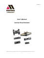
1
501:440-13
User’s Manual
Laminar Flow Elements
10920 Madison Avenue Cleveland, Ohio 44102▪Tel: 216.281.1100▪email:[email protected]▪Web:www.meriam.com
1
TABLE OF CONTENTS
Subject
Page
Introduction ................................................................................................................................................................ 3
Inspection ................................................................................................................................................................... 3
Installation .................................................................................................................................................................. 3
Operation .................................................................................................................................................................... 4
Typical Installations ................................................................................................................................................... 4
Calibration Curve/Table ............................................................................................................................................. 5
Actual Standard and Mass Flow Equations ........................................................................................................... 5-7
Reading your Laminar Flow Element Curve/Table .................................................................................................... 9
Correction Factor Tables/Curves
Air Humidity for Density ...................................................................................................................................... 8
Air Humidity for Viscosity .................................................................................................................................... 8
Pressure ............................................................................................................................................................... 12
Air Viscosity........................................................................................................................................................ 13
Air Temperature/Viscosity .................................................................................................................................. 14
Temperature......................................................................................................................................................... 15
Maintenance ............................................................................................................................................................ 14
Troubleshooting....................................................................................................................................................... 15
LFE Dimensions ..................................................................................................................................................... 17
2
Introduction
Because of their inherently high accuracy, stable calibration, excellent response time and repeatability,
Laminar Flow Elements (LFEs) excel in critical gas and air flow measurements and are frequently utilized
in validating calibration standards. Standard models are available to measure as little as 0.2 SCCM (5.9
E-06 SCFM) to as much as 2250 SCFM at standard conditions. Custom models for up to 15,000 SCFM of
air are available. Stainless steel or aluminum materials make LFEs compatible with most gases and flow
rate of gas mixtures can also be measured when the percentages of component gases and mixture properties
are known. Higher accuracies can be achieved when used in conjunction with the Meriam MDT500
multivariable transmitter and software package. The LFE matrix is made from individual SS tubes or
windings of SS foil, these tubes are long enough, relative to their inside diameter to cause laminar flow to
occur inside each tube, the result is a near linear relationship between DP and flow rate. The DP generated
across the matrix responds very quickly to changes in flow and pressure loss to the system is reduced as
each LFE is sized to produce no greater than 8” water column at maximum flowing conditions. Individual
tube diameters are very small so flowing gases need to be clean and dry to preserve the calibration.
Filtered inlet versions of most LFE models are available to keep the matrix clean and the calibration
constant.
This manual covers models 50MK10, 50MW20, 50MR2, 50MJ10, 50MC2 and 50MY15. For descriptions,
dimensions and capacities of these elements refer to Meriam Bulletin, File No. 501:215
Special Precautions When Handling Matrix Elements
The Meriam LFE depends on the precise fabrication of a matrix metering element for its basic
accuracy. These elements are manufactured from .001 inch stainless steel stock and are carefully
fabricated. Exercise extreme care when handling the exposed element to make sure the end faces are
not gouged or damaged in any fashion. Gouges or damage to the end surfaces may produce nonlinear
resistance to flow and introduce error. If the end surface becomes damaged, the accuracy of the
element may be restored by recalibration at the factory.
Inspection
1. Make sure you have unpacked all instructions and other data that accompanied the unit.
2. Visually inspect for any signs of damage. There must be no nicks or scratches, surfaces of the
LFE should be clear.
3. Units are shipped with a cap plug in each opening which protects the ends and pressure taps.
Remove these cap plugs.
4. Visually inspect matrix surface and inside housing. No capillaries should be blocked unless
specified in special applications.
Installation
Make sure the line is free of dirt and other foreign materials. The metered gas must be clean. In-line
use of filters is recommended. Connections to the differential pressure instrument should be made
with equal lengths of 1/4" I.D hose, tubing or pipe. All instrument connections must be leak- free.
Install temperature sensor 2-diameters upstream of the element. Inlet absolute pressure instrument,
when needed, must be connected close to the LFE at the inlet pressure tap. Figure 1 shows several typical
LFE installations.
Install the LFE in the line using hose connectors, flanges, tubing or pipe, as desired. Position the LFE
in any orientation. Horizontal is the most common. Orient the high-pressure and low-pressure sensing
ports in any angular direction. Flow must be in the direction of the arrow on the LFE. Avoid
disturbances upstream of the LFE. Good measurement practices dictate an adequate straight run of the
pipe up and downstream of the element. In most installations, 10 diameters upstream and 5
diameters downstream are adequate.
Where installation makes straight pipe runs impossible, LFE's can be calibrated with piping
configurations that duplicate installation. This special calibration assures installed accuracy. In these
applications, consult Meriam regarding calibration.
3
Operation
Establish flow through the LFE. Measure t h e differential pressure between high pressure sensing
port and low pressure sensing port. Measure the inlet gas temperature. For standard or mass flow
rates, measure absolute line pressure. Refer to calibration curve/table instructions for flow rate
calculations.
Standard or Mass Flow Rate
Actual Volumetric Flow Rate
4
Laminar Flow Systems
or MDT 500
Figure1: Typical Installations of Laminar Flow Elements Actual, Standard, or Mass Flow
Calibration Curve Table
Meriam performs an air calibration of the LFE using a master flowmeter that is traceable to the National
Standards and Technology (NIST). The calibration data is standardized to an equivalent dry gas flow rate at
70ºF (21.1ºC) and 29.92 inches Hg absolute (101.3 kPa abs.). (The customer may request another standard
condition such as OºC.) It is then possible to determine the actual or standard volumetric flow rate at your
flowing conditions. Each LFE has at least one calibration curve or table. The standard curve/table is for
dry air flow rate in units of cubic feet per minute (CFM) versus the differential pressure (DP) in inches of
water referenced to 4ºC produced by the LFE. You may request a curve/table for a different gas and/or for
different flow rate units. Each curve/ table is generated using a quadratic (second order) equation.
B x DP + C x DP² = Flow
The calibration constants B and C are printed on each curve/table.
Actual Volumetric Flow Rate
The LFE determines the actual volumetric flow rate. To obtain the actual volumetric flow rate, the
differential pressure across the LFE and the inlet temperature to the LFE is measured. Using the
calibration curve/table associated with the particular LFE; a flow rate value is
obtained by either
1) reading the value from the curve/table or:
2) using the formula, B x DP + C x DP² = Flow
Each curve has unique constants B and C. Multiply this flow rate value by the ratio:
(viscosityofflowinggasat70°Finmicropoise)
(viscosityofflowinggasatflowingtemperatureinmicropoise)
or μstd / µf. The product is the actual volumetric flow rate. (The curve/table lists the type of gas used
to generate the curve/table.)
Actual volumetric flow rate= (B x DP +C x DP²) x (
μstd
μf)
5
To help calculate the viscosity of air at flowing temperature, a viscosity equation based on temperature is
included in this instruction manual (see Table A-32422). The equation is from “tables of Thermodynamic
and transport Properties of Air, Argon, Carbon Dioxide, Oxygen, and Steam.” All other gas viscosity
equations are obtained from "Physical and Thermodynamic Properties of Pure Chemicals" Table A-31986
lists the values of μstd / µf for air from 50-159ºF at 1º intervals when the standard temperature is 70°F.
*Note: If you are flowing wet air, a humidity correction factor for viscosity must be used. The difference
between wet-air viscosity (µwet and dry-air viscosity (µdry) increases with temperature and humidity, at
80ºF and 80% relative humidity, the ratio of µwet / µdry is .997.
Figure 2 is a graph of the ratio µwet / µdry of air from 50 to 150ºF and from 10 to 90% relative humidity.
The viscosity of the flowing wet air becomes the value from the dry-air viscosity equation times the ratio
µwet / µdry
µf = µwet air =
Where T = ºK
)*+,
14.58+($)32
' x ( )-./ 0
(110.4+$)
The curve/table may have DP units of
1) inches of water column (WC)
2) centimeters of WC
3) millimeters of WC
4) pascals
5) kilopascals
Whenever a pressure is expressed in units of water, the water temperature reference must be given.
The calibration curve uses 4°C for the water temperature reference. Some devices use a water
temperature reference of 20ºC and others may use other temperature references. If no temperature
reference is given on the DP instrument or in its instruction manual, consult the manufacturer. If the
DP measuring device has a water temperature reference other than 4º, correct the DP reading by using
the following equation:
DP @ 4ºC = DP (device) x
-+123,/45678@,+:;+.<,=.+,+:;+.<,=.+.+5.
-+123,/45678@>°?
Water Temperature
4.0°C (39.2°F)
20.0°C (68.0°F)
15.5°C (60.0°F)
21.1°C (70.0°F)
Water Density (lbs/ft³)
62.426
62.316
62.366
62.301
The DP @ 4ºC value should be used with the curve/table.
Standard Volumetric Flow Rate
The word "standard" when associated with flow rate, means the flow rate has been normalized to an
assigned standard pressure and temperature. If standard volumetric flow rate is desired, the actual
volumetric flow rate is multiplied by the ratios.
@,<1-<.-,+:;+.<,=.+(A2,-)
5B4*31C,+:;+.<,=.+(A5)
and
5B4*31C;.+22=.+(D5)
2,<1-<.-;.+22=.+(D2,-)
6
Be sure to use the same absolute units for pressure (i.e. PSIA, mm Hg absolute,...) and temperature
(ºK or ºR). The result is the standard volumetric flow rate at the given standard conditions.
Standard volumetric flow rate = Actual volumetric flow rate x (
)2,-
(
This equation can be rewritten: (B x DP + C x DP²) x
A2,-
A2,-
0x(
)5
D5
0 x (D2,-0
A5
A5
D5
0 x (D2,-0
Table A-31031 lists the values of Pf/Pstd absolute line pressures from 26”Hg at 0.05” Hg intervals.
The standard pressure is 29.92” Hg absolute for this table. Table A-32422 lists the values of
(Tstd / Tf) x (µstd / µf) for air from 50 to 159ºF in 1º intervals. The standard temperature is 70ºF
(529.67ºR) for this table.
Note: If you are flowing wet air, a humidity correction factor for standard volumetric flow rate must
be used. The difference between wet-air density (Pwet) and dry-air density (Pdry) increases with
temperature and humidity. At 80°F and 80% relative humidity, the ratio of Pwet / Pdry is .990. Table
A-35600 lists the ratio Pwet / Pdry of air from 40 to 100°F and from 20 to 100% relative humidity.
The equation for standard volumetric flow rate of flowing wet air becomes:
Standard Volumetric Flow Rate Wet Air =
(B x DP + C x DP²) x (
)2,-
0x(
)*+,<3.
A2,A5
D5
D*+,
0 x (D2,-0 x ( D-./ 0
Mass Flow Rate
Multiply the standard volumetric flow rate by the density of the flowing gas at standard conditions to
obtain the mass flow rate of that gas.
Mass Flow rate = Standard volumetric flow rate x density @ standard conditions
Summary
Curve/table value @ DP = (B x DP + C x DP²)
)2,-
Actual volumetric flow rate = (B x DP + C x DP²) x (
)5
0
Standard volumetric flow rate = Actual volumetric flow rate x (
D5
D2,-
0x(
EFGH
EI
0
Mass flow rate = Standard volumetric flow rate x density @ standard conditions
7
Temperature oF
Air Viscosity Correction Factor for Humidity, Uwet/Udry
50
60
70
80
90 100 110 120 130 140 150
1
10% Humidity
20% Humidity
0.99
30% Humidity
40% Humidity
0.98
50% Humidity
60% Humidity
70% Humidity
0.97
80% Humidity
90% Humidity
0.96
Figure2: Relative humidity correction factor for air viscosity. A-35500 Kestin &
Whitelaw
Table A-35600 (NBSIR 83-2652)
Humidity Correction Factor for Air = Pwet / Pdry
% Relative Humidity
°F
20%
40%
60%
80%
100%
40
.9993
.9987
.9981
.9975
.9969
50
.9990
.9981
.9973
.9964
.9955
60
.9986
.9973
.9960
.9948
.9934
70
.9981
.9962
.9944
.9925
.9907
80
.9974
.9948
.9922
.9895
.9870
90
.9964
.9928
.9892
.9855
.9818
100
.9951
.9902
.9854
.9805
.9756
8
Determining Flow from your Laminar Flow Element
Calibration Curve/Table
The curve/table of each LFE is normalized to standard conditions listed by multiplying the calibration
data points by the ratio of:
J32K423,/45C<2<,K<B3L.<,341,+:;+.<,=.+
J32K423,/45C<2<,MN°O(2,<1-<.-,+:;+.<,=.+)
Therefore, you should NOT read the flow rate directly from the curve/table unless your flow
temperature and pressure are identical to the standard conditions. The following steps must be taken to
determine flow rate at flowing conditions other than standard.
1. Measure and correct to 4ºC and if necessary, the DP across the LFE.
2. Measure and record the inlet temperature (always) and absolute line pressure (for
s tandard or mass flow rates). Convert both values to absolute units.
3. Follow the AIR FLOW or GAS OTHER THAN AIR guidelines below
Model 50MK10
All Other Models
5
6
7
8
Flow, Q
0
1
2
3
Flow, Q
Flow, Q
4
0
4
1
2
3
4
Differential Pressure,
Inch of Water @ 4ºC
Differential Pressure,
Inch of Water @ 4ºC
Air Flow
Select the proper flow curve/table for the LFE being used.
Standard Volumetric Flow Rate
1) To obtain standard volumetric flow rate if inlet pressure and temperature are other than 29.92"
Hg absolute and 70ºF, respectively, find the flow rate (Q) that corresponds to the corrected DP.
Multiply Q by temperature/viscosity and pressure corrections shown on charts A-32422 and
A-31031, respectively, to bring flow to standard conditions of 29.92" Hg and 70ºF.
2) At flowing conditions of 70'F and 29.92" Hg, read curve directly in standard volumetric
flow rate.
9
Actual Volumetric Flow Rate
1) To obtain actual volumetric flow rate at inlet flowing temperature other than 70ºF, find
the flow rate (Q) that corresponds to the corrected DP. Multiply Q by the viscosity correction only.
See chart A-31986 for corrections.
2) At flowing inlet temperature of 70ºF read curve directly in actual volumetric flow rate.
Actual volumetric flow rate equals standard volumetric flow rate when flowing conditions are 70ºF
and 29.92" Hg.
Notify Meriam if your flowing gas is not air and/or standard conditions are different from 70ºF and
29.92" Hg absolute. A special curve/table can be provided listing the gas being flowed. The gas
viscosity correction, µstd / µf will reference the gas and/or new standard temperature value, if
applicable. Table A-32422 or A-31986 cannot be used for gases other than air.
Gas Flow Other Than Air/Standard Conditions From 70°F and 29.92” Hg ABS.
Select the proper flow curve/table for the LFE being used.
Standard Volumetric Flow Rate
1) To obtain standard volumetric flow rate if the inlet temperature and pressure are different from
standard, read the flow rate (Q) from the curve/table corresponding to the corrected differential
pressure (DP). Calculate the viscosity at the flowing temperature using the viscosity equation
for the flowing gas. Then calculate the viscosity correction factor (µcf) using
µcf =
P32K423,/K412,<1,5.4:K=.J+/,<LB+
5B4*31CC<2J32K423,/<,5B4*31C,+:;+.<,=.+
Locate the pressure correction factor (Pcf) for the flowing inlet pressure on chart A-31031 or
calculate the correction factor using
Pcf =
<L24B=,+31B+,B31+;.+22=.+
<L24B=,+2,<1-<.-;.+22=.+
Locate the temperature correction factor (Tcf) for the flowing temperature on chart A-35700 or
calculate using
Tcf =
<L24B=,+2,<1-<.-,+:;+.<,=.+
<L24B=,+5B4*31C,+:;+.<,=.+
Multiply Q from the curve/table by the viscosity correction factor (µcf), the pressure correction factor
(Pcf) and the temperature correction factor (Tcf). This product will give the flow rate of a particular
gas at the standard conditions.
2) At flowing inlet conditions equal to the standard conditions, read curve/table directly in standard
volumetric flow rate.
10
Actual Volumetric Flow Rate
1) To obtain actual volumetric flow rate if the inlet temperature is different from standard temperature,
read the flow rate (Q) from the curve corresponding to the corrected DP.
Calculate the viscosity at the flowing temperature using the viscosity equation for the flowing gas.
Then calculate the viscosity correction factor using
µcf =
J32K423,/K412,<1,5.4:K=.J+/,<LB+
5B4*31CC<2J32K423,/<,5B4*31C,+:;+.<,=.+
Multiply Q by the viscosity correction factor µcf. This product will give the flow rate of a particular
gas at the actual flowing conditions.
3) At flowing inlet temperature equal to the standard temperature, read the curve/table directly in
actual volumetric flow rate.
11
Table A-31031
Meriam Laminar Flow Element Pressure Correction Factor (any Gas) Base Pressure (Assigned
Standard) 29.92 Inches Mercury Absolute
LAMINAR INLET LAMINAR INLET
PRESSURE INCH PRESSURE INCH
HG. ABS
Pcf.
HG. ABS.
Pcf.
26.00
26.05
26.10
26.15
26.20
26.25
26.30
26.35
26.40
26.45
26.50
26.55
26.60
26.65
26.70
26.75
26.80
26.85
26.90
26.95
2700
27.05
27.10
2715
27.20
27.25
27.30
27.35
27.40
27.45
27.50
27.55
27.60
27.65
27.70
27.75
27.80
27.85
27.90
27.95
28.00
.8689
.8706
.8723
.8739
.8756
.8773
.8790
.8806
.8823
8840
.8856
.8873
.8890
.8907
8923
.8940
.8957
.8973
.8990
.9007
.9024
.9040
.9057
.9074
.9090
.9107
.9124
.9141
.9157
.9174
.9191
.9207
9224
.9241
.9258
.9274
.9291
.9308
.9324
.9341
.9358
28.05
28.10
28.15
28.20
28.25
28.30
28.35
28.40
28.45
28.50
28.55
28.60
28.65
28.70
28.75
28.80
28.85
28.90
28.95
29.00
29.05
29.10
29.15
29.20
29.25
29.30
29.35
29.40
29.45
29.50
29.55
29.60
29.65
29.70
29.75
29.80
29.85
29.90
29.92
29.95
30.00
.9375
.9391
.9403
.9425
.9441
.9458
.9475
.9491
.9508
.9525
.9542
.9558
.9575
.9592
.9608
.9625
.9642
.9659
.9675
.9692
.9709
.9725
.9742
.9759
.9776
.9792
.9809
.9826
.9842
.9859
.9876
.9893
.9909
.9926
.9943
.9959
.9976
.9993
1.0000
1.0010
1.0026
LAMINAR INLET
PRESSURE INCH
HG. ABS.
Pcf.
30.05
30.10
30.15
30.20
30.25
30.30
30.35
30.40
30.45
30.50
30.55
30.60
30.65
30.70
30.75
30.80
30.85
30.90
30.95
31.00
31.05
31.10
31.15
31.20
31.25
31.30
31.35
31.40
31.45
31.50
31.55
31.60
31.65
31.70
31.75
31.80
31.85
31.90
31.95
32.00
32.05
1.0043
1.0060
1.0076
1.0093
1.0110
1.0127
1.0143
1.0160
1.0177
1.0193
1.0210
1.0227
1.0243
1.0260
1.0277
1.0294
1.0310
1.0327
1.0344
1.0360
1.0377
1.0394
1.0411
1.0427
1.0444
1.0461
1.0477
1.0494
1.0511
1.0528
1.0544
1.0561
1.0578
1.0594
1.0611
1.0628
1.0645
1.0661
1.0678
1.0695
1.0711
LAMINAR INLET
PRESSURE INCH
HG. ABS.
Pcf.
32.10
32.15
32.20
32.25
32.30
32.35
32.40
32.45
32.50
32.55
32.60
32.65
32.70
32.75
32.80
32.85
32.90
32.95
33.00
33.05
33.10
33.15
33.20
33.25
33.30
33.35
33.40
33.45
33.50
33.55
33.60
33.65
33.70
33.75
33.80
33.85
33.90
33.95
34.00
34.05
34.10
1.0728
1.0745
1.0762
1.0778
1.0795
1.0812
1.0828
1.0845
1.0862
1.0879
1.0895
1.0912
1.0929
1.0945
1.0962
1.0979
1.0995
1.1012
1.1029
1.1046
1.1062
1.1079
1.1096
1.1112
1.1129
1.1146
1.1163
1.1179
1. 1196
1.1213
1.1229
1.1243
1.1263
1.1280
1.1296
1.1313
1.1330
1.1346
1.1363
1.1380
1.1397
LAMINAR INLET
PRESSURE INCH
HG. ABS.
Pcf.
34.15
34.20
34.25
34.30
34.35
34.40
34.45
34.50
34.55
34.60
34.65
34.70
34.75
34.80
34.85
34.90
34.95
35.00
35.05
35.10
35.15
35.20
35.25
35.30
35.35
35.40
35.45
35.50
35.55
35.60
35.65
35.70
35.75
35.80
35.85
35.90
35.95
36.00
For values not shown in table, interpolate or use equation:
Pcf
=
D5B4*
DR<2+
=
D5B4*
7S.S7
Pcf
= Pressure Conversion Factor
P base = Assigned Base Pressure of 29.92 inches mercury absolute
P flow = Laminar Inlet Pressure, inches mercury absolute
The equation can be used up to and including two atmospheres absolute. It will be necessary to
calibrate laminars for pressure exceeding above.
12
1.1413
1.1430
1.1447
1.1458
1.1480
1.1497
1.1514
1.1530
1.1547
1 1564
1.1580
1.1597
1.1614
1.1631
1.1647
1.1664
1.1681
1.1697
1.1714
1.1731
1.1747
1.1764
1.1781
1.1798
1.1814
1.1831
1. 1848
1.1864
1.1881
1.1898
1.1915
1.1931
1.1948
1.1965
1.1981
1.1998
1.2015
1.2032
Table A-31986
Air Viscosity Correction Factors for ACFM Base Viscosity 181.87 Micropoise at 70°F
Correction Factor =
TUT.V
)W∗
Note: These correction factors do not correct for volume changes due to temperature
Temp
°F
+0
+1
+2
+3
+4
+5
+6
+7
+8
+9
50
1.03034
1.02877
1.02720
1.02564
1.02408
1.02253
1.02099
1.01945
1.01792
1.01639
60
1.01487
1.01336
1.01185
1.01035
1.00885
1.00736
1.00588
1.00440
1.00292
1.00146
70
1.0000
0.99854
0.99709
0.99564
0.99420
0.99277
0.99134
0.98992
0.98850
0.98709
80
0.98568
0.98428
0.98288
0.98149
0.98010
0.97872
0.97734
0.97597
0.97461
0.97325
90
0.97189
0.97054
0.96919
0.96785
0.96651
0.96518
0.96386
0.96253
0.96122
0.95991
100
0.95860
0.95729
0.95600
0.95470
0.95341
0.95213
0.95085
0.94957
0.94830
0.94704
110
0.94578
0.94452
0.94327
0.94202
0.94077
0.93953
0.93830
0.93707
0.93584
0.93462
120
0.93340
0.93219
0.93098
0.92977
0.92857
0.92737
0.92618
0.92499
0.92380
0.92262
130
0.92144
0.92027
0.91910
0.91794
0.91678
0.91562
0.91446
0.91331
0.91217
0.91103
140
0.90989
0.90875
0.90762
0.90650
0.90537
0.90425
0.90314
0.90203
0.90092
0.89981
150
0.89871
0.89761
0.89652
0.89543
0.89434
0.89326
0.89218
0.89110
0.89003
0.88896
13
Table A-32422
Air Temperature/Viscosity Correction Factors for SCFM Air Base
T e m p e r a t u r e 7 0 °F 181.7 Micropoise Reference NBS Circular 564
Correction Factor =
YZ[.\V
]Y[.\V^°_
x
TUT.V
)W∗
µair =
14.58 x (
110.4 +
(
]Y[.\V^°` a
T.U
]Y[.\V^°`
T.U
0
0
Z
Temp
°F
+0
+1
+2
+3
+4
+5
+6
+7
+8
+9
50
1.0707
1.0670
1.0633
1.0596
1.0559
1.0523
1.0487
1.0451
1.0415
1.0379
60
1.0344
1.0308
1.0273
1.0238
1.0204
1.0169
1.0135
1.0101
1.0067
1.0033
70
1.0000
.9966
.9933
.9900
.9867
.9834
.9802
.9770
.9737
.9705
80
.9674
.9642
.9611
.9579
.9548
.9517
.9486
.9456
.9425
.9395
90
.9365
.9335
.9305
.9275
.9246
.9216
.9187
.9158
.9129
.9100
100
.9072
.9043
.9015
.8987
.8959
.8931
.8903
.8875
.8848
.8820
110
.8793
.8766
.8739
.8712
.8686
.8659
.8633
.8606
.8580
.8554
120
.8528
.8503
.8477
.8452
.8426
.8401
.8376
.8351
.8326
.8301
130
.8276
.8252
.8227
.8203
.8179
.8155
.8131
.8107
.8083
.8060
140
.8036
.8013
.7990
.7966
.7943
.7920
.7898
.7875
.7852
.7830
150
.7807
.7785
.7763
.7741
.7719
.7697
.7675
.7653
.7632
.7610
* When flowing gas other than air, use the viscosity in micropoise of the gas at flowing temperature in
the Correction Factor equation.
Table A-35700
Temperature Correction Factor
Base Temperature = 70°F
Tcf =
Maintenance
YZ[.\V
(]Y[.\V^°`)
Accumulation of dirt in the capillaries of the laminar element will affect the accuracy. When in
doubt, hold the laminar in front of a high intensity light, sighting through the capillaries. Any dirt
will be apparent. Loose dirt can be blown out with shop air (no more than 100 PSI) in reverse direction
of flow. Shop air must be clean and dry. Brushing or rubbing the ends of the matrix element is not
recommended because the matrix can be deformed, altering the calibration. Unless the customer has the
facilities and primary standards to check calibration after cleaning, we recommend returning the unit to
Meriam for cleaning and calibration.
14
Temp
°F
+0
+1
+2
+3
+4
+5
+6
+7
+8
+9
50
1.0392
1.0372
1.0352
1.0332
1.0311
1.0291
1.0271
1.0252
1.0232
1.0212
60
1.0192
1.0173
1.0153
1.0134
1.0115
1.0095
1.0076
1.0057
1.0038
1.0019
70
1.0000
0.9981
0.9962
0.9944
0.9925
0.9906
0.9888
0.987
0.9851
0.9833
80
0.9815
0.9797
0.9778
0.976
0.9742
0.9725
0.9707
0.9689
0.9671
0.9654
90
0.9636
0.9619
0.9601
0.9584
0.9567
0.9549
0.9532
0.9515
0.9498
0.9481
100
0.9464
0.9447
0.943
0.9414
0.9397
0.938
0.9364
0.9347
0.9331
0.9314
110
0.9298
0.9282
0.9265
0.9249
0.9233
0.9217
0.9201
0.9185
0.9169
0.9153
120
0.9137
0.9122
0.9106
0.909
0.9075
0.9059
0.9044
0.9028
0.9013
0.8998
130
0.8982
0.8967
0.8952
0.8937
0.8922
0.8907
0.8892
0.8877
0.8862
0.8847
140
0.8833
0.8818
0.8803
0.8789
0.8774
0.876
0.8745
0.8731
0.8716
0.8702
150
0.8688
0.8674
0.8659
0.8645
0.8631
0.8617
0.8603
0.8589
0.8575
0.8561
Troubleshooting
Problem
Low or High
DP Indication
Pulsating /
Irregular Reading
Probable Cause
Remedy
Insufficient or improperly sized straight pipe
downstream and/or upstream of LFE.
Use 10 diameters of straight pipe
upstream and 5 diameters of straight
pipe downstream of LFE. Pipe size
should be same as LFE outlet size,
e.g. ½" NPT on LFE means 10
diameters of ½” pipe.
One or both differential pressure
connection taps plugged.
Clean or check instrument
connecting line.
If pulsation dampener is used, check stones
(Model 50 MR2 and 50 MC2 only).
If plugged, replace with matched
pair (Meriam part #A-31650).
Leak in line between LFE and readout
device.
Detect and repair.
Large-volume and/or unequal-volume
connecting lines to readout device.
Use small-volume and equal
volume connecting lines to readout
device. See Installation on page 4.
Piping reducers at inlet and/or outlet.
Do not use reducers immediately
before or after LFE.
Irregular flow pattern entering LFE.
Use at least 10 diameters of straight
pipe upstream of LFE.
Leak in system line.
Detect and repair.
15
When you decide to have your LFE cleaned, please be aware of the various capabilities of calibrating
LFE’s at Meriam. Every calibration includes: 6-8 calibration points [differential pressure 1”-8”H2O], a data
sheet with raw and reduced data, calibration curve, and instruction manual. The procedure numbers are
noted in (parentheses).
Calibrations
NIST Traceable Certificate
(% Reading)
( )
Clean per (A33555) and calibrate per (A35822) Working-Master
( )
Clean per (A33555) and calibrate per (A35822) Master-Master
( )
As Received calibration (A35822/A34777), clean, and calibrate [WM]
( )
As Received calibration (A35822/A34777), clean, and calibrate [MM]
( )
Accredited calibration ISO/IEC 17025 (contact Sales for details)
( )
Nuclear or safety application (A33544)
( )
Subcontracted per (A35352)
Options
( )
( )
( )
( )
( )
( )
( )
X
X
X
X
X
X
X
Accuracy
±0.72% R
±0.54% R
±0.72% R
±0.54% R
±0.64% R
±0.72% R
±0.50% R
2 additional calibration points beyond full scale- up to 12”H2O
Additional calibration points beyond full scale at the following settings _____________________.
Additional calibration points below 1”H2O at the following settings _______________________.
Oxygen cleaning per (A50558)
Calibrating the LFE with differential pressure transmitter
Hydrostatic leak testing per (A33559)
Pneumatic pressure test per (A70763)
The standard reference unit for flow rate is (cfm) cubic feet per minute. The additional units available are:
( )
Liters
( )
Cubic Centimeters
( )
Meters
( )
Pounds (include flowing temperature and pressure)
( )
Kilograms (include flowing temperature and pressure)
( )
Other _____________________
Time constants:
( )
Second
( )
Minute
( )
Hour
The standard reference for differential pressure is inches of water at 4°C. The additional units available are:
( )
Millimeters of water @ 4°C
( )
Centimeters of water @ 4°C
( )
Pascals
( )
Kilopascals
( )
Other _____________________
A second data sheet and calibration curve using the listed units will be included with the calibration
16
LFE Dimensions
17