1
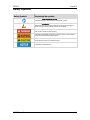
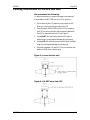
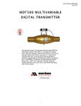
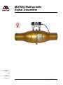
® MDT500 Multivariable Digital Transmitter 10920 Madison Ave Cleveland · Ohio 44102 1-216-928-1100 1-800-817-7849 www.Meriam.com Copyright © 2015 Meriam® 9R216-A May 2015 Advisory statements Disclaimer Every precaution has been taken in the preparation of this manual. Nevertheless, Meriam assumes no responsibility for errors or omissions or any damages resulting from the use of the information contained in this publication, including, without limitation, incidental, special, direct or consequential damages. MERIAM MAKES NO REPRESENTATIONS OR WARRANTIES WITH RESPECT TO THE ACCURACY OR COMPLETENESS OF THE CONTENTS HEREOF AND SPECIFICALLY DISCLAIMS ANY IMPLIED WARRANTIES OF MERCHANTABILITY OR FITNESS FOR ANY PARTICULAR PURPOSE. Meriam reserves the right to revise this publication and to make changes from time to time in the content hereof without obligation to notify any person of such revision or changes. Copyright This publication is proprietary to Meriam and no ownership rights are transferred. Neither this manual, nor any of the material contained herein, may be reproduced without the prior written consent of Meriam. Trademarks LabVIEW® LabVIEW® is a registered trademark of National Instruments. MDT500 User Manual 2 9R216-A May 2015 Safety Symbols Safety Symbols Explaining the symbols This is the Read Instruction Manual symbol. This symbol indicates that you must read the instruction manual. This is the Safety Alert symbol. This symbol indicates a WARNING. Warnings alert you to actions that can cause personal injury or pose a physical threat. Please read these carefully. Indicates a potentially hazardous situation which, if not avoided, will result in death or serious injury. Indicates a potentially hazardous situation which, if not avoided, could result in death or serious injury. Indicates a potentially hazardous situation which, if not avoided, could result in minor or moderate injury. Indicates information essential for proper product installation, operation or maintenance. MDT500 User Manual 3 9R216-A May 2015 Safety Information Preventing injury Failure to follow all instructions could result in injury: Read. Understand. Follow all safety warnings and instructions provided with this product. Fire or Explosion Hazard This instrument is not intrinsically safe. Do not use or service in areas that may contain flammable gas or vapors, combustible dusts or ignitable fibers where an unintended spark can cause a fire or explosion. Pressure Limits Do not exceed the Pressure Limits listed in the Specifications section of this manual. Failure to operate within the specified pressure limit could result in death or serious injury. Maximum Input Voltage 1. Do not exceed the Maximum Input Voltage listed under manual 2. Disconnect power before servicing. 3. Substitution of components may impair operation and safety. MDT500 User Manual 4 9R216-A May 2015 Meriam Contact Information Meriam Process Technologies Address Meriam Process Technologies 10920 Madison Avenue Cleveland, Ohio 44102 USA Telephone US customers: + 1-800-817-7849 International customers: + 1-216-281-1100 Fax US customers: + 1-216-281-0228 International customers: + 1-216-281-0228 E-mail addresses Website Departments E-mail addresses Return Material Authorization / Service & Repair Department [email protected] Sales [email protected] www.meriam.com Local Meriam Representatives Find a local Meriam representative MDT500 User Manual To find a find local Meriam representative, use this map to find contact information: REP LOCATOR. 5 9R216-A May 2015 Contents Software Updates ......................................... 13 Advisory statements ........................................2 Disclaimer .................................................2 Copyright ...................................................2 Trademarks .....................................................2 LabVIEW® ..................................................2 Safety Symbols ................................................3 Safety Symbols..........................................3 Explaining the symbols .............................3 Safety Information ...........................................4 Preventing injury .......................................4 Fire or Explosion Hazard ...........................4 Pressure Limits .........................................4 Maximum Input Voltage............................4 Meriam Contact Information ...........................5 Included with the MDT500 ..............................7 Contents ....................................................7 CD ROM Resources ..................................7 USB Drivers on the CD ..............................7 Interface Accessories ......................................8 Part numbers for accessories ..................8 Installation and Operation ...............................9 Updating the firmware ........................... 13 Install the Meriam Setup Utility ............. 13 Service and Calibration ................................. 14 Overview ................................................. 14 Meriam Shipping and Receiving Policies ................................................................ 14 Returning for repairs ..................................... 15 First — Request a Number .................... 15 Return Material Authorization ............... 15 Questions? Call Meriam ........................ 15 Ship the box to ....................................... 15 Packing Instructions for the LFE and MDT .... 16 We recommend the following: ............... 16 Figure 1—Loosen the hex nuts .............. 16 Figure 2—Lift MDT away from LFE......... 16 Specifications ............................................... 17 Overall Technical Specifications ............... 17 Specifications (continued) ............................ 18 Resistance or Temperature Measurement ..................................................................... 18 Specifications (continued) ............................ 19 Software Environment ..............................9 MDT and LFE Connections ............................10 Resistance or Temperature Measurement (continued) ................................................. 19 Certifications: CE Markings ........................... 20 Properly using the RTD Probe ................10 50MC2 / 50MR2 Series LFE ..................10 MDT and LFE Connections (continued) .........11 Compliant with European Directives ..... 20 Hazardous Material and Recycling Compliance ...................................................................... 20 50MK10, 50MJ10, 50MW20, 50MH10, 50MY15 Series LFE ................................11 Zeroing the MDT500 .....................................12 Compliant with European Directives ..... 20 Spare Parts ................................................... 21 Zeroing the Differential Pressure Sensor .................................................................12 Unzip the MDT Config Executable from the CD ......................................................12 MDT500 User Manual Spare part numbers ............................... 21 6 9R216-A May 2015 Included with the MDT500 Contents RTD Probe USB cable CD-ROM A NIST traceable calibration certificate for model numbers: Model Calibration ZMDT-X-X purchased without an LFE will receive a multi-point pressure calibration. ZMDT-X-X-MT and LFE purchased as a system will receive a 3-point air flow calibration. CD ROM Resources Each MDT500 comes with a product CD ROM that includes the following resources: LabVIEW Drivers (VIs). Manual Meriam Setup Utility. Meriam Software Development Kit. USB Drivers. Note: Please look at these resources when we refer to them in this manual. USB Drivers on the CD You must install USB drivers on the computer you use with the MDT500 before the MDT500 will function. You can find these drivers on the product CD or in the Software Dev Kit at www.meriam.com. MDT500 User Manual 7 9R216-A May 2015 Interface Accessories Part numbers for accessories The following table lists part numbers for various accessories available to assist you in configuring or communicating with the MDT500. MDT500 User Manual Part Number Description Accessory Status Z9A000003PN06 MDT500 Product CD ROM Standard, all models Z9P703 Male Adapter Standard, LFE mounted model ZA36894-3 Male Connector Standard, LFE mounted model 8 9R216-A May 2015 Installation and Operation Software Environment The MDT500 is designed to be operated with a Windows computer and the Meriam Software Development Kit (SDK). This kit is provided to make it easier to integrate with your systems. The SDK includes libraries for calculating flow rate and for communicating with the device to take measurements and access configuration options. Example applications are provided as source code and as executables that implement key features of the Virtual Flow Instrument library. Note: You can use the SDK as both a .NET Class Library and a LabVIEW VI Library. Read the Meriam_SDK_Overview.pdf and the Help file located in the SDK Documentation directory on the CD for details. MDT500 User Manual 9 9R216-A May 2015 MDT and LFE Connections Properly using the RTD Probe 1. Connect the supplied RTD Probe before you use the MDT500. 2. Do not allow the RTD probe sheath to directly contact line voltage. For example: 120 V ac. 3. Use with high power (500 mA) USB ports or powered USB hubs only. 4. Keep at least four inches from high-power, 3-phase cables. 5. Do not run in parallel with 3-phase power cables. 6. Cross existing AC power cables at right angle only when necessary for routing purposes. 50MC2 / 50MR2 Series LFE MDT500 User Manual 10 9R216-A May 2015 MDT and LFE Connections (continued) 50MK10, 50MJ10, 50MW20, 50MH10, 50MY15 Series LFE MDT500 User Manual 11 9R216-A May 2015 Zeroing the MDT500 Zeroing the Differential Pressure Sensor Meriam recommends zeroing the MDT500 Differential Pressure Sensor before using it and periodically thereafter as needed. Use the MDT Config example application included in the Meriam SDK to zero the sensor. (You can find this utility on the product CD or in the Software Dev Kit at www.meriam.com.) Unzip the MDT Config Executable from the CD 1. Unzip %InstallationDirectory%\Meriam\SDK\Examples\CSharp\ MDT Config Executable (You may have to unzip it to a location other than the Program Files or Program Files(x86) directory). 2. Launch MDT Config.exe. 3. Set the appropriate Com Port and click the Connect button. Note: You can find the Com Port number of the MDT500 using Windows Device Manager\Ports. The MDT500 appears as Meriam Product. 4. Then click the Zero button in the Differential Pressure section. MDT500 User Manual 12 9R216-A May 2015 Meriam recommends zeroing the MDT500 in its final mounting position to null any orientation effects due to local gravity. Software Updates Updating the firmware Meriam periodically issues new operating firmware to improve MDT500 operation and features. You can upgrade all MDT500 units with new firmware using the EI Reflash Utility software included on the CD. Install the Meriam Setup Utility Follow these steps to install the Meriam Setup Utility. 1. Connect the MDT500 to the host PC. 2. Navigate to the Meriam Setup Utility directory and open EI Reflash Utility.exe. 3. Select COM Port and baud rate (115200). Note: You can find the Com Port number of the MDT500 using Windows Device Manager\Ports. The MDT500 appears as Meriam Product. 4. Click Check Web to download updates, then Auto Update to ensure the MDT500 has the latest firmware and features. MDT500 User Manual 13 9R216-A May 2015 Service and Calibration Overview If you need to service an MDT500 or it requires recertification or re-calibration, please follow the instructions on this page and the next two pages. Meriam Shipping and Receiving Policies 1. Abandoned Material Policy: Material is classified as abandoned after it has been in our possession for a period of 30 days after being quoted with no activity. In such cases, Meriam will notify you, at the last known contact point, that Meriam considers your material abandoned. And, in accordance with our policy, the material will be disposed of within ten business days. Meriam will not replace or provide credit for abandoned materials. 2. Non-Hazardous Material Certification: This is to certify that the equipment being returned with the serial number listed above is not known to be contaminated with any hazardous substance. 3. Data Loss Agreement: Meriam is not responsible for any loss, corruption or breach of data on any product during the Service & Repair process and it is my responsibility to appropriately backup my unit prior to having it serviced and repaired. MDT500 User Manual 14 9R216-A May 2015 Returning for repairs First — Request a Number In the event that the MDT and LFE requires service and must be returned for repair, please contact Meriam using one of the methods listed in the following table to request a Return Material Authorization (RMA) number: Method Information Website: http://www.meriam.com/resources/service-repairauthorization/ Complete information online and submit the form. If you printed and completed the Service & Repair Authorization form, then fax it to: Fax: US Customers + 1-216-281-0228 International customers + 1-216-281-0228 We need the following information in the email: E-mail: Look for the Model number & the Serial number to provide it. Give a brief description of the problem. Send the e-mail to: [email protected] Return Material Authorization Do not send any unit for repair unless you contacted Meriam for a Return Material Authorization (RMA) number. Important: If you have not received this number and clearly marked it on the package being shipped back, we will return the unit at your expense. The Meriam Service & Repair Department will provide you with this number when you complete the website form, fax or e-mail your information. An RMA number must accompany all incoming packages to insure proper tracking, processing, and repair work. Questions? Call Meriam US Customers + 1-800-817-7849 International customers + 1-216-281-1100 Ship the box to Meriam Process Technologies 10920 Madison Avenue Cleveland, Ohio 44102 USA MDT500 User Manual 15 9R216-A May 2015 Packing Instructions for the LFE and MDT We recommend the following: To lessen the possibility of shipping damage, we recommend that you detach the MDT500 from the LFE for shipping. 1. When returning the LFE, make sure you protect the LFE Matrix by covering up the open ends of the LFE. 2. Carefully detach the MDT500 from the LFE by loosening the 9/16" hex nuts on the two male connectors attached to the MDT to separate from the LFE (see Figure 1). 3. Package MDT with sufficient protective KEM pack or bubble wrap to protect against damage during shipping. 4. Package LFE with sufficient protective KEM pack or bubble wrap to protect against damage during shipping. 5. Place both packaged LFE and MDT into one container with additional KEM pack or bubble wrap. Figure 1—Loosen the hex nuts Figure 2—Lift MDT away from LFE MDT500 User Manual 16 9R216-A May 2015 Specifications Overall Technical Specifications Specifications and Certifications Description Media Compatibility Clean, dry, non-corrosive gases only (brass, 316 SS, Viton, Silicon gel) Software Supported Operating Systems Vista Windows XP Windows 7 Environment .NET Framework 4.0 Software Development Kit (SDK) Example Programs with Source Code in LabVIEW® and C# Supporting .NET (C# / VB) Pressure Measurement Operating Temperature –4 °F to 122 °F (–20 °C to 50 °C) Pressure Update Rate 7 readings per second from both differential and absolute pressure sensors Optional Pressure Ranges Differential Sensor: o 12 inches water column at 20 °C. o NIST Traceable Accuracy: ± 0.05 % of full scale including all effects of linearity, repeatability, hysteresis, and temperature (–20 °C to 50 °C) Absolute Sensor: o 38 psia o 100 psia o NIST Traceable Accuracy: ± 0.025 % of full scale including all effects of linearity, repeatability, hysteresis, and temperature (–20 °C to 50 °C) Differential Sensor: o 2x range when pressurized on P1 (HI) side only; o 150 psi when applied simultaneously to P1 (HI) & P2 (LO) sides Absolute Sensor: 2x range Differential Sensor: Clean, dry, non-corrosive gases only (brass, 316 SS, Viton®, Silicon gel) Absolute Sensor: Media compatible with 316 SS Over Range Limits Media Compatibility MDT500 User Manual 17 9R216-A May 2015 Specifications (continued) Resistance or Temperature Measurement Resistance or Temperature Measurement Description NIST Traceable Accuracy ± 1 °F including all effects of linearity, repeatability, hysteresis, and temperature with Pt100 Probe connected. Operating Temperature –4 °F to 122 °F (–20 °C to 50 °C) Temperature Update Rate 14 readings per second Temperature Sensor Specifications Specification Description Accuracy Class A Tolerance Class (per IEC 60751) Temperature Range 58 °F to 482 °F (-50 °C to 250 °C) Connector is 185 °F (85 °C Max) Material 316L stainless steel sheath and housing Temperature Probe Pt100 — 100 ohms at 0 °C, 0.00385 TCR (alpha) Probe Dimensions 1/4" diameter, 6" long Connections 5-meter-M12, molded cord set P1 and P2 Pressure Ports: 1∕4" NPT (female) Mechanical Flushing Ports: 5/16 – 24 SAE/MS J1926 (316L SS plugs included) Electrical / Communication USB: type B female connector Analog: circular, locking connector for RTD probe Power Requirements MDT500 User Manual Computer USB: high power (500 mA) USB port or USB hub Note: Computer USB ports and USB hubs with power adapters that are typically high power. 18 9R216-A May 2015 Specifications (continued) Resistance or Temperature Measurement (continued) Resistance or Temperature Measurement Enclosure Description Specification Description Protection IP40 Dimensions (in./mm) H x 2.6", W x 3.6", L x 5.6" H x 66 mm, W x 91 mm, L x 142 mm Material Plastic (ABS) Weight Mounting Temperature Limits Humidity Limits MDT500 User Manual 1.5 lbs. Hook-up fittings add 0.26 lbs. (0.118 kg) Laminar Flow Element mounting hardware provided. Specification Description Operating –4 °F to 122 °F (–20 °C to 50 °C) Storage –40 °F to 185 °F (–40 °C to 85 °C) Operating: 5–95 % RH 19 9R216-A May 2015 Certifications: CE Markings Compliant with European Directives This product is compliant with the European directives: Directive Description EN 61326-1 Electrical equipment for measurement, control and laboratory use - EMC requirements. Note 1: For use only in a controlled emc environment, typically found in a test, measurement and calibration environment. Note 2: Classified as cat-1 (voltages not present or measured above 60 V dc) IEC 61010 Safety requirements for electrical equipment for measurement, control and laboratory use. Note 2: Classified as CAT-1 (voltages not present or measured above 60 V dc) Hazardous Material and Recycling Compliance Compliant with European Directives This product is compliant with the European directives: Directive Description RoHS Directive 2011/65/EU Reduction of Hazardous Substances WEEE 2012/19/EU Waste from Electrical and Electronic Equipment Note: The following marking indicates that you must not discard this electrical / electronic product in domestic household waste. MDT500 User Manual 20 9R216-A May 2015 Spare Parts Spare part numbers Contact [email protected] to purchase these parts or for more information about the following part numbers. Or see Meriam Contact Information page. MDT500 User Manual Part Number Description Z9P703 Adapter-Male-Machine – 1/4" Tube × 1/4"” MNPT Brass ZA36894-3 Male Connector 1/4" Tube × 1/4"” MNPT Brass Z9P273 Cable, USB, Type “A” To Mini “B” Z9P713 Cable, RTD-4 Pos Plug-Socket 5.0 M Z9P521 Probe-RTD Sensor 21