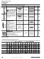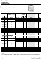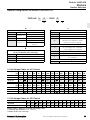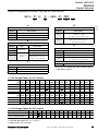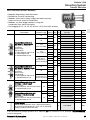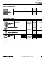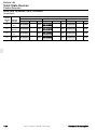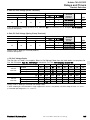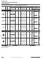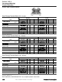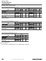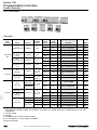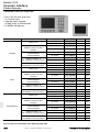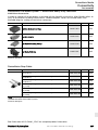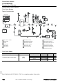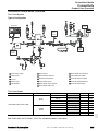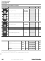
1
ESSENTIAL COMPONENTS, EXCEPTIONAL VALUE Essential Components Catalogue September 2005 ESSENTIAL COMPONENTS, EXCEPTIONAL VALUE. Welcome to the latest edition of the Essential Components Catalogue from Rockwell Automation, where you will find many new and exciting products introduced over recent months. IT’S ALL ABOUT YOUR SUCCESS. Your success drives Rockwell Automation innovation, and it has for more than 100 years. We’re intensely focused on your success by engineering essential components with exceptional value, helping you and your machines compete with anyone, anywhere, anytime. LISTEN. THINK. SOLVE. At Rockwell Automation, we’re committed to listening to, thinking about, and solving your automation challenges. Your success is our success. PREFERRED PRODUCTS Preferred products are standard stock items. They are identified in the catalog with bold catalog numbers. PACKAGE QUANTITY (PQ) All products without packaging information are single pack (PQ = 1). Orders must correspond to the multiple of the indicated packaging quantity. Packaging cannot be divided. DISCOUNT GROUP The product range is divided into different discount groups. PRODUCT GROUP CODE (PGC) Discount groups are subdivided into different product group codes. TERMS AND CONDITIONS «General Terms and Conditions of Sale» can be found in publication «6500(EN) - January 2004». This publication is available as a PDF file (Adobe Acrobat) at http://www.rockwellautomation.com/termsofsale. Circuit Breakers 4 Contactors 23 Motor Protection 49 Starters 65 Mounting System 79 Soft Starters 91 Drives 103 Solid State Devices 119 Temperature Controllers 129 Power Supplies 135 Relays and Timers 143 Circuit Protection 167 Control and Load Switches 179 Control and Indicating Units 197 Terminal Blocks 249 Programmable Controllers 259 Operator Interface 285 Sensors and Safety 295 Connectivity 327 Solutions and Services 339 Bulletin 140A, 140M, 140-CM Circuit Breakers Product Line Overview Circuit Breakers 140A, Manual Motor Starter 140M-RC2 140M-C2 140M-D8 Spring Clamp Terminals — 9 — — Screw Terminals 9 — 9 9 Max. Current Ie 16 A 16 A 25 A 25 A Current Rating 1.6…25 A Bulletin 0.1…16 A 0.1…16 A 0.1…25 A Short Circuit Protection 9 9 9 9 Standard Magnetic Trip 9 9 9 9 High Magnetic Trip — — 9 9 Overload Pro otection 9 9 9 9 Trip Class 10 10 10 10 Magnetic Only Trip (MCP) — — 9 9 Standards Compliance: CSA 22.2, No. 14 9 9 9 9 UL 508 Manual, Self Protected (Type E) 9 9 9 9 UL 508 (Group Install.) 9 9 9 9 UL 508 (Overload Protection) 9 9 9 9 IEC 60947-2 9 9 9 9 IEC 60947-4 9 9 9 9 CE 9 9 9 9 Accessories Ext. Rotary Operator — 9 9 9 Flex Cable Operator — — — — Auxiliary Contacts 9 9 9 9 Trip Indication Contacts 9 9 9 9 Page 6 Page 9 Page 10 Page 10 Product Selection 4 Visit our website: www.ab.com/catalogs Rockwell Automation Bulletin 140A, 140M, 140-CM Circuit Breakers Product Line Overview Circuit Breakers Bulletin Spring Clamp Terminals 140M-F8 140-CM 140M-K, -M, -P — — — Screw Terminals 9 9 9 Max. Current Ie 45 A 90 A 160 A, 250 A, 400 A Current Rating 50…400 A 6.3…45 A 16…90 A Short Circuit Protection 9 9 9 Standard Magnetic Trip 9 9 9 — High Magnetic Trip 9 9 Overload Pro otection 9 9 9 Trip Class 10 10 5, 10, 15, 20 Magnetic Only Trip (MCP) 9 — — Standards Compliance: CSA 22.2, No. 14 9 9 — UL 508 Manual, Self Protected (Type E) 9 — — UL 508 (Group Install.) 9 9 — UL 508 (Overload Protection) 9 9 — IEC 60947-2 9 9 9 IEC 60947-4 9 9 9 CE 9 9 9 9 es Accessorie Ext. Rotary Operator 9 9 Flex Cable Operator — — 9 Auxiliary Contacts 9 9 9 Trip Indication Contacts Product Selection Rockwell Automation 9 9 9 Page 10 Page 10 Page 20 Visit our website: www.ab.com/catalogs 5 Bulletin 140A Manual Motor Starters Product Selection Manual Motor Starters 140A y Current Range 0.1…16 A y Motor Protection y For Economical Motor Starters y Usable as Main Switch y Temperature Compensated y Worldwide applicable because of the conformity with IEC, UL (USA and Canada) 140A-C2A 3-Pole Manual Motor Starters Rated Operational Motor Current Current (Ie) Adjustment Range Switching of 3-Phase AC Motors AC-2, AC-3 @ 400/415V (50 Hz) 9 [A] [A] [kW] Icu = Ics [kA] Cat. No. PGC 0.16 A 0.1…0.16 0.02 65 140A-C2A-A16 W9G9 0.25 A 0.16…0.25 0.06 65 140A-C2A-A25 W9G9 0.4 A 0.25…0.4 0.09 65 140A-C2A-A40 W9G9 0.63 A 0.4…0.63 0.12/0.18 65 140A-C2A-A63 W9G9 1.0 A 0.63…1.0 0.25 65 140A-C2A-B10 W9G9 1.6 A 1.0…1.6 0.37/0.55 65 140A-C2A-B16 W9G9 2.5 A 1.6…2.5 0.75 50 140A-C2A-B25 W9G9 4.0 A 2.5…4.0 1.1/1.5 10 140A-C2A-B40 W9G9 6.3 A 4.0…6.3 2.2 10 140A-C2A-B63 W9G9 10 A 6.3…10 3.0/4.0 8 140A-C2A-C10 W9G9 16 A 10…16 5.5/7.5 6 140A-C2A-C16 W9G9 9 Power ratings: Preferred values according to IEC 60072-1 Discount Group MAC Accessories 140A Description Term. No. N.O. N.C. 13-14 1 0 Auxiliary Contact for Flush Mounting 1-pole No additional space required 33-34 1 0 11-12 0 1 31-32 0 Auxiliary Contact for Left-side Mounting 2-pole Adds 9 mm to the width of the Manual Motor Starter Use compact bus bars with 54 mm spacing 13-14 23-24 For Use With Cat. No. PGC 140A-C-AEA10 W9G9 140A-C-AEA210 W9G9 140A-C-AEA01 W9G9 1 140A-C-AEA201 W9G9 2 0 140A-C-ASA20 W9G9 13-14 21-22 1 1 140A-C-ASA11 W9G9 11-12 21-22 0 140A-C-ASA02 W9G9 140A 140A 2 Discount Group MAC See Publication 140-SG001_-EN-P for complete product information. 6 Visit our website: www.ab.com/catalogs Rockwell Automation Bulletin 140A Manual Motor Starters Accessories Accessories 140A For Use With Description Undervoltage Trip Release For right-side mounting Adds 18 mm to the width of the Manual Motor Starter Cat. No. PGC 24V 60 Hz 140A-C-UXJ W9G9 24V 50 Hz 140A-C-UXK W9G9 220…230V 50 Hz 140A-C-UXF W9G9 240V 50 Hz / 277V 60 Hz 140A-C-UXT W9G9 140A-C-UXN W9G9 415V 50 Hz / 480V 60 Hz 140A-C-UXB W9G9 110V 50 Hz / 120V 60 Hz 140A-C-UXD W9G9 240…260V 60 Hz 140A-C-UXA W9G9 400V 50 Hz / 460V 60 Hz 140A 140A-C-UXKD W9G9 24V 60 Hz 140A-C-SXJ W9G9 24V 50 Hz 140A-C-SXK W9G9 220…230V 50 Hz 140A-C-SXF W9G9 240V 50 Hz / 277V 60 Hz 140A-C-SXT W9G9 140A-C-SXN W9G9 415V 50 Hz / 480V 60 Hz 140A-C-SXB W9G9 110V 50 Hz / 120V 60 Hz 140A-C-SXD W9G9 240…260V 60 Hz 140A-C-SXA W9G9 110V 50 / 60 Hz Shunt Trip Release For right-side mounting Adds 18 mm to the width of the Manual Motor Starter 400V 50 Hz / 460V 60 Hz 140A 110V 50 / 60 Hz 140A-C-SXKD W9G9 Compact Bus Bars 45 mm spacing for manual motor starters with flushmounted auxiliary contact blocks 2 x 3 Terminal links 140A-C-W452 W9G9 140A-C-W453 W9G9 140A-C-W454 W9G9 5 x 3 Terminal links 140A-C-W455 W9G9 Compact Bus Barss 54 mm spacing for manual motor starters with sidemounted auxiliary contact blocks 2 x 3 Terminal links 140A-C-W542 W9G9 140A-C-W543 W9G9 140A-C-W544 W9G9 140A-C-W545 W9G9 3 x 3 Terminal links 4 x 3 Terminal links 3 x 3 Terminal links 4 x 3 Terminal links 140A 140A 5 x 3 Terminal links Bus Bar Feeder Terminal Supply of compact busbars Increases wiring capacity 140A-C-W 140A-C-WT W9G9 Blank Space Cover For covering unused terminal links 140A-C-W 140A-C-WS W9G9 Emergency-Stop Push Button Set For use with enclosures Twist to release 140A-C-E… 140A-C-MT55 W9G9 Emergency-Sttop Push Button Set For use with enclosures Key release 140A-C-E… 140A-C-MK55 W9G9 Discount Group MAC See Publication 140-SG001_-EN-P for complete product information. Rockwell Automation Visit our website: www.ab.com/catalogs 7 Bulletin 140A Manual Motor Starters Accessories Accessories 140A Description Enclosures for Surface Protection Class: IP41 Mounting With centre marks for 2 indicator lights Protection Class: IP55 Includes protective earth and (with seal and protective neutral wire terminals membrane) Protection Class: IP41 Enclosures for Flush Mounting Includes protective earth and Protection Class: IP55 neutral wire terminals (with seal and protective membrane) Button Membrane For IP55 enclosures Replacement part with 4 screws (mounting frame included) For Use With Cat. No. PGC 140A 140A-C-EA41 W9G9 140A 140A-C-EA55 W9G9 140A 140A-C-EE41 W9G9 140A 140A-C-EE55 W9G9 140A-C-EA55 140A-C-N18 140A-C-EE55 W9G9 120V Indicator Lights Mounting in upper part of enclosure Length of connection leads: 180 mm Includes lamp Protection Class: IP54 Suitable for enclosures 140A-C-E… green red 240V 140A-C-E… 140-LG120 W9G 140-LG240 W9G 400V 140-LG400 W9G 120V 140-LR120 W9G 140-LR240 W9G 240V 140A-C-E… 400V 140-LR400 W9G 120V 140-LW120 W9G 140-LW240 W9G 140-LW400 W9G 140A-C-E… 140A-C-M3E W9G9 Locking Arrangement For locking ON-button of the Manual Motor Starter For 1…3 padlocks with ø 4…6 mm 140A 140A-C-M3 W9G9 Screw Adapter Hut (DIN) rail 35 x 7.5 mm, length 44 mm 140A 140A-C-N12 W9G9 white 240V 140A-C-E… 400V Locking Arrangement Suitable for enclosures 140A-C-E… For 1…3 padlocks with ø 4…8 mm Discount Group MAC See Publication 140-SG001_-EN-P for complete product information. 8 Visit our website: www.ab.com/catalogs Rockwell Automation Bulletin 140M Circuit Breakers Product Selection Motor Protection Circuit Breakers 140M with Spring Clamp Terminals y Short Circuit Protection — Standard Magnetic Trip (Fixed at 13 x Ie) y Overload Protection — Trip Class 10 (Adjustable Current Range) y Ambient temperature compensation y Phase-loss protection 140M-RC Rated Operational Current (Ie) Motor Current Adjustment Range [A] [A] Switching of 3-Phase AC Motors AC-2, AC-3 @ 400/415V (50 Hz) [kW] Icu [kA] Ics [kA] Cat. No. PGC C-Frame 0.16 A 0.10…0.16 0.02 100 100 140M-RC2E-A16 W9G1 0.25 A 0.16…0.25 0.06 100 100 140M-RC2E-A25 W9G1 0.40 A 0.25…0.40 0.09 100 100 140M-RC2E-A40 W9G1 0.63 A 0.40…0.63 0.12/0.18 100 100 140M-RC2E-A63 W9G1 1.0 A 0.63…1.0 0.12 100 100 140M-RC2E-B10 W9G1 1.6 A 1.0…1.6 0.18/0.25 100 100 140M-RC2E-B16 W9G1 2.5 A 1.6…2.5 0.37 100 100 140M-RC2E-B25 W9G1 4.0 A 2.5…4.0 0.55/0.75 100 100 140M-RC2E-B40 W9G1 6.3 A 4.0…6.3 1.1/1.5 100 100 140M-RC2E-B63 W9G1 10 A 6.3…10 2.2 100 100 140M-RC2E-C10 W9G1 16 A 10…16 3.0/4.0 50 50 140M-RC2E-C16 W9G1 Discount Group MAC Rockwell Automation Visit our website: www.ab.com/catalogs 9 Bulletin 140M, 140-CM Circuit Breakers Product Selection Motor Protection Circuit Breakers 140M, 140-CMN y Short Circuit Protection — Standard Magnetic Trip (Fixed at 13 x Ie) y Overload Protection — Trip Class 10 (Adjustable Current Range) y Ambient temperature compensation y Phase-loss protection 140M-C2E Rated Operational Current (Ie) Motor Current Adjustment Range [A] [A] Switching of 3-Phase AC Motors AC-2, AC-3 @ 400/415V (50 Hz) [kW] Icu [kA] Ics [kA] Cat. No. PGC C-Frame 0.16 A 0.10…0.16 0.02 100 100 9 140M-C2E-A16 W9G1 0.25 A 0.16…0.25 0.06 100 100 9 140M-C2E-A25 W9G1 0.40 A 0.25…0.40 0.09 100 100 9 140M-C2E-A40 W9G1 0.63 A 0.40…0.63 0.12...0.18 100 100 9 140M-C2E-A63 W9G1 1.0 A 0.63…1.0 0.25 100 100 9 140M-C2E-B10 W9G1 1.6 A 1.0…1.6 0.37...0.55 100 100 9 140M-C2E-B16 W9G1 2.5 A 1.6…2.5 0.75 100 100 9 140M-C2E-B25 W9G1 4.0 A 2.5…4.0 1.1...1.5 100 100 9 140M-C2E-B40 W9G1 6.3 A 4.0…6.3 2.2 100 100 9 140M-C2E-B63 W9G1 10 A 6.3…10 3.0...4.0 100 100 9 140M-C2E-C10 W9G1 16 A 10…16 5.5...7.5 50 50 9 140M-C2E-C16 W9G1 20 A 14.5…20 7.5...10 15 15 9 140M-C2E-C20 W9G1 25 A 18…25 11 15 15 9 140M-C2E-C25 W9G1 W9G1 D-Frame 2.5 A 1.6…2.5 0.75 100 100 140M-D8E-B25 4.0 A 2.5…4.0 1.1...1.5 100 100 140M-D8E-B40 W9G1 6.3 A 4.0…6.3 2.2 100 100 140M-D8E-B63 W9G1 10 A 6.3…10 3.0...4.0 100 100 140M-D8E-C10 W9G1 16 A 10…16 5.5...7.5 100 100 140M-D8E-C16 W9G1 20 A 14.5…20 7.5...10 65 25 140M-D8E-C20 W9G1 25 A 18…25 11 65 25 140M-D8E-C25 W9G1 10 A 6.3…10 3.0...4.0 65 50 140M-F8E-C10 W9G1 16 A 10…16 5.5...7.5 65 50 140M-F8E-C16 W9G1 20 A 14.5…20 7.5...10 65 50 140M-F8E-C20 W9G1 25 A 18…25 11 65 50 140M-F8E-C25 W9G1 32 A 23…32 15 65 50 140M-F8E-C32 W9G1 45 A 32…45 18.5...22 65 50 140M-F8E-C45 W9G1 F-Frame CMN-Frame 25 A 16…25 7.5...13 65 65 140-CMN-2500 W9H 40 A 25…40 15...22 65 50 140-CMN-4000 W9H 63 A 40…63 25...32 65 50 140-CMN-6300 W9H 90 A 63…90 37...45 50 25 140-CMN-9000 W9H 9 May be ordered in package quantities of 20. Add letter M to the end of the cat. no. (Example: 140M-C2E-A16M). Discount Group MAC 10 Visit our website: www.ab.com/catalogs Rockwell Automation Bulletin 140M Circuit Breakers Product Selection Circuit Breakers 140M, Short-Circuit Protection for Starters y Short Circuit Protection — Standard Magnetic Trip (Fixed at 13 x Ie) y Overload Protection — None (Magnetic Trip Only) y Suitable for Transformer Protection (IEC only) 140M-C2N Rated Operational Current (Ie) [A] Switching of 3-Phase AC Motors AC-2, AC-3 @ 400/415V (50 Hz) [kW] Icu [kA] Ics [kA] Cat. No. PGC C-Frame 0.16 A 0.02 100 100 9 140M-C2N-A16 W9G1 0.25 A 0.06 100 100 9 140M-C2N-A25 W9G1 0.40 A 0.09 100 100 9 140M-C2N-A40 W9G1 0.63 A 0.12...0.18 100 100 9 140M-C2N-A63 W9G1 1.0 A 0.25 100 100 9 140M-C2N-B10 W9G1 1.6 A 0.37...0.55 100 100 9 140M-C2N-B16 W9G1 2.5 A 0.75 100 100 9 140M-C2N-B25 W9G1 D-Frame 2.5 A 0.75 100 100 9 140M-D8N-B25 W9G1 4.0 A 1.1...1.5 100 100 9 140M-D8N-B40 W9G1 6.3 A 2.2 100 100 9 140M-D8N-B63 W9G1 10 A 3.0...4.0 100 100 9 140M-D8N-C10 W9G1 16 A 5.5...7.5 100 50 9 140M-D8N-C16 W9G1 25 A 11 65 25 9 140M-D8N-C25 W9G1 F-Frame 25 A 11 65 50 140M-F8N-C25 W9G1 32 A 15 65 50 140M-F8N-C32 W9G1 45 A 18.5...22 65 50 140M-F8N-C45 W9G1 9 May be ordered in package quantities of 20. Add letter M to the end of the cat. no. (Example: 140M-C2N-A16M). Discount Group MAC Rockwell Automation Visit our website: www.ab.com/catalogs 11 Bulletin 140M, 140-CM Circuit Breakers Product Selection Circuit Breakers 140M, 140-CMT; Transformer Protection y Short Circuit Protection — High Magnetic Trip (Fixed at 16…20 x Ie) y Overload Protection — Trip Class 10 y Transformer Protection 140M-C2T Rated Operational Current (Ie) Motor Current Adjustment Range [A] [A] Switching of 3-Phase AC Motors AC-2, AC-3 @ 400/415V (50 Hz) [kW] Icu [kA] Ics [kA] Cat. No. PGC C-Frame 0.16 A 0.10…0.16 0.02 100 100 9 140M-C2T-A16 W9G1 0.25 A 0.16…0.25 0.06 100 100 9 140M-C2T-A25 W9G1 0.40 A 0.25…0.40 0.09 100 100 9 140M-C2T-A40 W9G1 0.63 A 0.40…0.63 0.12...0.18 100 100 9 140M-C2T-A63 W9G1 1.0 A 0.63…1.0 0.25 100 100 9 140M-C2T-B10 W9G1 1.6 A 1.0…1.6 0.37...0.55 100 100 9 140M-C2T-B16 W9G1 2.5 A 1.6…2.5 0.75 100 100 9 140M-C2T-B25 W9G1 4.0 A 2.5…4 1.1...1.5 100 100 9 140M-C2T-B40 W9G1 6.3 A 4…6.3 2.2 100 100 9 140M-C2T-B63 W9G1 10 A 6.3…10 3.0...4.0 100 100 9 140M-C2T-C10 W9G1 16 A 10…16 5.5...7.5 50 15 9 140M-C2T-C16 W9G1 D-Frame 16 A 10…16 5.5...7.5 65 25 9 140M-D8T-C16 W9G1 20 A 14.5…20 7.5...10 65 25 9 140M-D8T-C20 W9G1 F-Frame 25 A 18…25 11 65 50 140M-F8T-C25 W9G1 32 A 23…32 15 65 50 140M-F8T-C32 W9G1 CMT-Frame 40 A 25…40 15/22 65 50 140-CMT-4000 W9H 63 A 40…63 25/31.5 65 50 140-CMT-6300 W9H 9 May be ordered in package quantities of 20. Add letter M to the end of the cat. no. (Example: 140M-C2T-A16M). Discount Group MAC 12 Visit our website: www.ab.com/catalogs Rockwell Automation Bulletin 140M, 140-CM Circuit Breakers Accessories Accessories 140M, 140-CM Description Front-Mounted Auxiliary Contact 1-pole or 2-pole No additional space required - Only (1) per MPCB Term. No. N.O. N.C. Cat. No. PGC 13-14 1 0 140M-C, 9 D, F 140M-C-AFA10 W9G5 11-12 0 1 140M-C, D, F 140M-C-AFA01 W9G5 1 1 140M-C, 9 D, F 140M-C-AFA11 W9G5 2 0 140M-C, D, F 140M-C-AFA20 W9G5 0 2 140M-C, D, F 140M-C-AFA02 W9G5 2 0 140M-C, D, F 140M-C-ASA20 W9G5 0 2 140M-C, D, F 140M-C-ASA02 W9G5 1 1 140M-C, 9 D, F 140M-C-ASA11 W9G5 13-14 1 0 140M-R 140M-RC-AFA10 W9G1 11-12 0 1 140M-R 140M-RC-AFA01 W9G1 1 1 140M-R 140M-RC-AFA11 W9G1 2 0 140M-R 140M-RC-AFA20 W9G1 2 0 140-CM 140-CA20 W9H 0 2 140-CM 140-CA02 W9H 1 1 140-CM 140-CA11 W9H 13-14 21-22 13-14 23-24 11-12 21-22 33-34 Right Side-Mounted Auxiliary Contact 2-pole Adds 9 mm to the width of the device - (2) per MPCB 43-44 31-32 41-42 33-34 41-42 Front-Mounted Auxiliary Contact 1-pole or 2-pole No additional space required - Only (1) per MPCB Front-Mounted Auxiliary Contact 1-pole or 2-pole No additional space required 13-14 21-22 13-14 23-24 13-14 Front-Mounted Auxiliarry Contact Internal 2-pole - (1) per MPCB 23-24 11-12 21-22 13-14 21-22 For Use With 9 May be ordered in package quantities of 20. Add letter M to the end of the cat. no. (Example: 140M-C-AFA10M). Discount Group MAC Rockwell Automation Visit our website: www.ab.com/catalogs 13 Bulletin 140M, 140-CM Circuit Breakers Accessories Accessories 140M, 140-CM Description Front-Mounted Trip Contact 2-pole Indicates tripping of device No additional space required Term. No. 13-14 27-28 N.C. For Use With Cat. No. PGC 140M-C-AFAR10A10 W9G5 2 0 140M-C, D, F 1 1 140M-C, D, F 140M-C-AFAR10A01 W9G5 2 0 140M-C, 140M-C-ASAR10M10 D, F W9G5 1 1 140M-C, 140M-C-ASAR10M01 D, F W9G5 1 1 140M-C, 140M-C-ASAR01M10 D, F W9G5 0 2 140M-C, 140M-C-ASAR01M01 D, F W9G5 1 1 140M-C, D, F W9G5 2 0 140M-R 140M-RC-AFAR10A10 W9G5 1 1 140M-R 140M-RC-AFAR10A01 W9G5 2 0 140-CM 140-CT10-10 W9H 0 2 140-CM 140-CT01-01 W9H 1 1 140-CM 140-CT01-10 W9H 1 1 140-CM 140-CT10-01 W9H 11-12 27-28 Right SideMounted Trip Contact 2-pole Indicates tripping of Motor Protection Circuit Breaker Adds 9 mm to the width of the circuit breaker - Only (1) per MPCB - A Right Sidemounted Auxiliary Contact may be tandem mounted on top of this Trip Contact 57-58 Front-Mounted Trip Contact 2-pole Indicates tripping of device No additional space required 13-14 67-68 57-58 65-66 55-56 67-68 55-56 65-66 77-78 65-66 27-28 140M-C-ASAM11 11-12 27-28 37-38 43-44 Front-Mounted Trip-Indicating ntact Auxiliary Con Internal 2-pole - (1) per MPCB N.O. 35-36 41-42 35-36 43-44 37-38 41-42 Discount Group MAC 14 Visit our website: www.ab.com/catalogs Rockwell Automation Bulletin 140M, 140-CM Circuit Breakers Accessories Accessories 140M, 140-CM Description Trip Rating For Use With 24V, 60 Hz Undervoltage Trip Left-side mounted Adds 18 mm to the width of the circuit breaker Automatically trips MPCB/MCP when voltage falls below 35-70% Undervoltage Trip Left-side mounted 2 early make contacts integrated Adds 18 mm to the width of the circuit breaker Automatically trips MPCB/MCP when voltage falls below 35-70% Shunt Trip Left-side mounted Adds 18 mm to the width of the circuit breaker Provides remote tripping of the MPCB/MCP Underrvoltage Trip Unit Internal, front mounted Integrated short-circuit trip indication Automatically trips MPCB when voltage falls below 35-70% Shunt Trip Unit Internal, front mounted Integrated short-circuit trip indication Provides remote tripping of the MPCB Cat. No. PGC 140M-C-UXJ W9G5 24V, 50 Hz 140M-C-UXK W9G5 120V, 60 Hz 140M-C-UXD W9G5 110V, 50 Hz 140M-C-UXC W9G5 140M-C-UXF W9G5 220…230V, 50 Hz 140MC, D, F 140M-C-UXA W9G5 277V, 60 Hz 140M-C-UXT W9G5 240…260V, 60 Hz 380…400V, 50 Hz 140M-C-UXN W9G5 480V, 60 Hz/415V, 50 Hz 140M-C-UXB W9G5 575V, 60 Hz/500V, 50 Hz 140M-C-UXM W9G5 24V, 60 Hz 140M-C-UCJ W9G5 24V, 50 Hz 140M-C-UCK W9G5 120V, 60 Hz 140M-C-UCD W9G5 110V, 50 Hz 140M-C-UCC W9G5 140M- 140M-C-UCF C, D, F 140M-C-UCA W9G5 277V, 60 Hz 140M-C-UCT W9G5 220…230V, 50 Hz 240…260V, 60 Hz W9G5 380…400V, 50 Hz 140M-C-UCN W9G5 480V, 60 Hz/415V, 50 Hz 140M-C-UCB W9G5 575V, 60 Hz/500V, 50 Hz 140M-C-UCM W9G5 24V, 60 Hz 140M-C-SNJ W9G5 24V, 50 Hz 140M-C-SNK W9G5 120V, 60 Hz 140M-C-SND W9G5 110V, 50 Hz 140M-C-SNC W9G5 140M- 140M-C-SNF C, D, F 140M-C-SNA W9G5 277V, 60 Hz 140M-C-SNT W9G5 220…230V, 50 Hz 240…260V, 60 Hz W9G5 380…400V, 50 Hz 140M-C-SNN W9G5 480V, 60 Hz/415V, 50 Hz 140M-C-SNB W9G5 575V, 60 Hz/500V, 50 Hz 140M-C-SNM W9G5 24V, 50/60 Hz 140-CUV-KJ W9H 110V, 50 Hz/120V, 60 Hz 140-CUV-D W9H 220V, 50 Hz/240V, 60 Hz 140-CUV-A W9H 24V, 50/60 Hz 140-CRT-KJ W9H 110V, 50 Hz/120V, 60 Hz 140-CRT-D W9H 140-CRT-A W9H 140-CM 140-CM 220V, 50 Hz/240V, 60 Hz Discount Group MAC Rockwell Automation Visit our website: www.ab.com/catalogs 15 Bulletin 140M, 140-CM Circuit Breakers Accessories Accessories 140M, 140-CM For Use With Cat. No. PGC 140M-C, D, F 140M-C-CA W9G5 Lockable Twist Knob Black 140M-C, D, F For 1 padlock 4…8 mm (5/16 in.) dia. Red/Yellow 140M-C/-D shackle Red/Yellow 140M-F Can be locked in OFF position 140M-C-KN W9G5 140M-C-KRY W9G5 140M-F-KRY W9G5 140-KN W9H 140-KRY W9H 140M-C, D, F 140M-C-DN66 W9G5 140-CM 140-CDN66 W9H Description Anti-Tamper Shield Provides protection against inadvertent adjustment of the current setting Package quantity = 10 9 Padlockable Operating Knob Black Accepts 8 mm (5/16 in.) padlock — up to three padlocks Permits padlocking in the off position Red/Yellow Door Coupling Handle For 3 padlocks 4…8 mm (5/16 in.) in diameter IP66 Protection/Type 1, 12 Interlock override capability Can be modified for locking in ON position Ships with coupling — order extension shaft and legend plate separately Mounting depth (adapter-door): 140-C: 105.5 mm ± 5 mm (4.5 in. ± 3/16 in.) 140-D: 114.5 mm ± 5 mm (4.5 in. ± 3/16 in.) 140-F: 137.1 mm ± 5 mm (5.4 in. ± 3/16 in.) 140-CM Black 140M-C, D, F 140M-C-DRY66 W9G5 Red/Yellow Extension Shaft Cut to required length for mounting depth (adapter-door): 140M-C: 117…338 mm (4.6 in.…13.3 in.) 140M-D: 126…347 mm (5.0 in.…13.7in.) 140M-F: 149…369 mm (5.4 in.…14.5 in.) 140-CMN: 180…403 mm (7.1 in.…15.9 in.) 140-CM 140-CDRY66 W9H 140M-CDN66, 140M-CDRY66, 140-CDN66, 140-CDRY66 140M-C-DS W9G5 140-CDN66 Legend Plate Marking: "Hauptschalter" and "Main Switch" Marking: "Not-Aus" and "Emergency Off" 140M-C-DFCN W9G5 140-CDRY66 140M-C-DFCRY W9G5 Locking Tag Padlock attachment to the lockable handles Up to three padlocks 4…8 mm (5/16 in.) shackle 140M-C-KN 140M-C-KRY 140M-F-KRY W9G5 140M-C-M3 9 Sold only in multiples of 10. Order (quantity of) 10 to receive one package of 10 pieces. Discount Group MAC 16 Visit our website: www.ab.com/catalogs Rockwell Automation Bulletin 140M Circuit Breakers Accessories Accessories 140M Cat. No. Description For Use With IP65 Non-Metallic Enclosure Knockouts for PG16 and PG21 Handle 198E-AYTG2 140M-C fittings Black Suitable for flexible cable with internal ground wire or conduit when Handle externally grounded around the 198E-AYTJ2 140M-C Red/Yellow outside of the enclosure Terminal Cover For covering of unused Commoning Link terminals IP2X finger protection Screw Adapter For screw arrangement of a Motor Protection Circuit Breaker Package quantity = 10 9 Disconnector Module Provides visible isolation from line side connections to the Bulletin 140M-C, -D circuit breakers. Can be removed or put in a "park" position. Padlockable with up to 2 padlocks 3...6mm (1/4") in diameter. PGC W9T W9T 140M-C, 140M-D 140M-C-WS W9G5 140M-F 140M-F-WS W9G5 140M-C, D, F 140M-C-N45 W9G5 140M-C-TRE W9G5 140M-C, -D 9 Sold only in multiples of 10. Order (quantity of) 10 to receive one package of 10 pieces. Discount Group MAC Rockwell Automation Visit our website: www.ab.com/catalogs 17 Bulletin 140M Circuit Breakers Accessories Accessories 140M Description For Use With Cat. No. ECO Connecting Modules — 25 A 140M-C to 100-M 9 140M-C-PEM12 Eco-starters mount on SINGLE DIN Rail 140M-C to 1009 140M-C-PEC23 (140M on DIN Rail) C09…C23 ELECTRICAL AND MECHANICAL interconnection of 140M MPCB and 100-M 140M-D to 1009 140M-D-PEC23 (with AC or DC coils) or 100-C (with AC C09…C23 coils) contactors Connecting Modules — 25 A and 45 A • Contactor and MPCB MUST BE mounted separately on (2) DIN Rails ELECTRICAL interconnection between 140M MPCB and 100-C contactors (with AC coils) Spacing Adapter Required for Self-Protected combination motor controller (Type E) applications of 140M-C, -D, and -F MPCBs act Compa Bus Bar Feeder Block Supply of compact busbars Increases terminal capacity IEC terminal spacings UL terminal spacings Compact Busbar Feeder Terminal For supply of commoning links Top feed — overlaps commoning link PGC W9G5 W9G5 W9G5 140M-C to 100C09…C23 140M-C-PNC23 W9G5 140M-D to 100C09…C23 140M-D-PNC23 W9G5 140M-D to 100C30…C37 140M-D-PNC37 W9G5 140M-F to 100C30…C37 140M-F-PNC37 W9G5 140M-F to 100C43 140M-F-PNC43 W9G5 140M-C, -D 140M-C-TE W9G5 140M-F 140M-F-TE W9G5 140M-C, -D 140M-C-WB W9G5 140M-C, -D 140M-C-WBE W9G5 140M-F 140M-F-WBE W9G5 140M-C, -D 140M-C-WTE W9G5 140M-F 140M-F-WTE W9G5 Communication Module DeviceNet Starter Auxiliary DSA I/O for Distributed Starters, see page 38 9 May be ordered in package quantities of 20. Add letter M to the end of the cat. no. (Example: 140M-C-PEM12M). Discount Group MAC 18 Visit our website: www.ab.com/catalogs Rockwell Automation Bulletin 140M Circuit Breakers Accessories Accessories 140M No. of For Use Description Connections With Three-Phase Compact Busbar for 25 2 A Motor Protection Circuit Breakers — 3 63 A Max. Continuous Curren nt 140M-C, -D 4 45 mm spacing For use with front-mounted auxiliary 5 contact Three-Phase Compact Busbar for 25 A Motor Protection Circuit Breakers — 63 A Max. Continuous Curren nt 54 mm spacing For use with side-mounted auxiliary contact Three-Phase Compact Busbar for 25 A Motor Protection Circuit Breakers — 63 A Max. Continuous Curren nt 63 mm spacing For use with side-mounted undervoltage trip and shunt trip Three-Phase Compact Busbar for 45 A Motor Protection Circuit Breakers — 115 A Max Continuous Curren nt 54 mm spacing For use with front-mounted auxiliary contact Three-Phase Compact Busbar for 45 A Motor Protection Circuit Breakers — 115 A Max Continuous Curren nt 63 mm spacing For use with side-mounted auxiliary contact Jumper for 140M-D to 140M-C Accommodates difference in depth from 140M-D to 140M-C 54 mm spacing Can be used with all other commoning links Cat. No. PGC 140M-C-W452 W9G5 140M-C-W453 W9G5 140M-C-W454 W9G5 140M-C-W455 W9G5 2 140M-C-W542 W9G5 3 140M-C-W543 W9G5 140M-C-W544 W9G5 5 140M-C-W545 W9G5 2 140M-C-W632 W9G5 3 140M-C-W633 W9G5 140M-C-W634 W9G5 5 140M-C-W635 W9G5 2 140M-F-W542 W9G5 3 140M-F-W543 W9G5 4 140M-F-W544 W9G5 2 140M-F-W632 W9G5 3 140M-F-W633 W9G5 140M-F-W634 W9G5 140M-C-WD542 W9G5 4 4 140M-C, -D 140M-C, -D 140M-F 140M-F 4 2 140M-D to 140M-C Discount Group MAC Rockwell Automation Visit our website: www.ab.com/catalogs 19 Bulletin 140M-K, -M, -P Circuit Breakers Product Selection Motor Protection Circuit Breakers 140M-K, -M, -P y Short Circuit Protection — Standard Magnetic Trip (Fixed at 13 x Ie) y Overload Protection — Trip Class 10 (Adjustable Current Range) y Ambient temperature compensation y Phase-loss protection 140M-K5F 3-Pole Circuit Breakers Rated Operational Current (Ie) Motor Current Adjustment Range Switching of 3-Phase AC Motors AC-2, AC-3 @ 400/415V (50 Hz) Icu [kA] Ics [kA] [A] [A] [kW] Cat. No. PGC 50 40…50 25 65 33 140M-K5F-C50 W9G2 63 50…63 32 65 33 140M-K5F-C63 W9G2 80 63…80 37/45 65 33 140M-K5F-C80 W9G2 100 80…100 50/55 65 33 140M-K5F-D10 W9G2 125 100…125 63 65 33 140M-K5F-D12 W9G2 160 125…160 75/90 65 33 140M-K5F-D16 W9G2 160 125…160 75/90 65 33 140M-M5F-D16 W9G2 200 160…200 110 65 33 140M-M5F-D20 W9G2 250 200…250 132/150 65 33 140M-M5F-D25 W9G2 250 200…250 132/150 65 33 140M-P5F-D25 W9G2 320 250…320 160/185 65 33 140M-P5F-D32 W9G2 400 320…400 200/220 65 33 140M-P5F-D40 W9G2 Discount Group MAC 4-Pole Circuit Breakers Rated Operational Current (Ie) Motor Current Adjustment Range Switching of 3-Phase AC Motors AC-2, AC-3 @ 400/415V (50 Hz) Icu [kA] Ics [kA] [A] [A] [kW] Cat. No. PGC 50 40…50 25 65 33 140M-K5F4-C50 W9G2 63 50…63 32 65 33 140M-K5F4-C63 W9G2 80 63…80 37/45 65 33 140M-K5F4-C80 W9G2 100 80…100 50/55 65 33 140M-K5F4-D10 W9G2 125 100…125 63 65 33 140M-K5F4-D12 W9G2 160 125…160 75/90 65 33 140M-K5F4-D16 W9G2 160 125…160 75/90 65 33 140M-M5F4-D16 W9G2 200 160…200 110 65 33 140M-M5F4-D20 W9G2 250 200…250 132/150 65 33 140M-M5F4-D25 W9G2 250 200…250 132/150 65 33 140M-P5F4-D25 W9G2 320 250…320 160/185 65 33 140M-P5F4-D32 W9G2 400 320…400 200/220 65 33 140M-P5F4-D40 W9G2 Discount Group MAC 20 Visit our website: www.ab.com/catalogs Rockwell Automation Bulletin 140M-K, -M, -P Circuit Breakers Accessories Accessories 140M-K, -M, -P Description Auxiliary Contact Block for Internal Mounting Leads labelled and fitted with terminal sleeves Trip Contact Block for Internal Mounting Leads labelled and fitted with terminal sleeves Auxiliary and Trip Contact Block for Internal Mounting Leads labelled and fitted with terminal end covers 140M-K-EA22 W9G6 140M-P-EA11 W9G6 140M-P-EA22 W9G6 140M-K 140M-K-ER11 W9G6 140M-M, -P5F 140M-P-ER11 W9G6 140M-K 140M-K-EA11R11 W9G6 140M-M, -P5F 140M-P-EA11R11 W9G6 W9G6 140M-K 140M-M, -P5F 140M-K5F 140M-K-UKJ 140M-P-UKJ W9G6 110…127V 50/60 Hz 140M-K5F 140M-K-UKD W9G6 140M-K5F 140M-P-UKD W9G6 208…240V 50/60 Hz 140M-K5F 140M-K-UKF W9G6 140M-M, -P5F 140M-P-UKF W9G6 140M-K5F 140M-K-UKN W9G6 140M-M, -P5F 140M-P-UKN W9G6 140M-K5F 140M-K-UZJ W9G6 380…480V 50/60 Hz 24V DC 110…127V DC 220…250V DC 24V 50/60 Hz 110…127V 50/60 Hz Shunt Trip for Internal Mounting Leads labelled and fitted with terminal end covers PGC W9G6 140M-M, -P5F 24V 50/60 Hz Undervoltage Trip for Internal Mounting Leads labelled and fitted with terminal end covers Cat. No. 140M-K-EA11 For Use With 208…240V 50/60 Hz 380…480V 50/60 Hz 24V DC 110…127V DC 220…250V DC 140M-M, -P5F 140M-P-UZJ W9G6 140M-K5F 140M-K-UZD W9G6 140M-M, -P5F 140M-P-UZD W9G6 140M-K5F 140M-K-UZA W9G6 140M-M, -P5F 140M-P-UZA W9G6 140M-K5F 140M-K-AKJ W9G6 140M-M, -P5F 140M-P-AKJ W9G6 140M-K5F 140M-K-AKD W9G6 140M-M, -P5F 140M-P-AKD W9G6 140M-K5F 140M-K-AKF W9G6 140M-M, -P5F 140M-P-AKF W9G6 140M-K5F 140M-K-AKN W9G6 140M-M, -P5F 140M-P-AKN W9G6 140M-K5F 140M-K-AZJ W9G6 140M-M, -P5F 140M-P-AZJ W9G6 140M-K5F 140M-K-AZD W9G6 140M-M, -P5F 140M-P-AZD W9G6 140M-K5F 140M-K-AZA W9G6 140M-M, -P5F 140M-P-AZA W9G6 Discount Group MAC Rockwell Automation Visit our website: www.ab.com/catalogs 21 Bulletin 140M-K, -M, -P Circuit Breakers Accessories Accessories 140M-K, -M, -P For Use With Description Black knob Complete Door Assembly Consists of: door-mounted actuator with clutch, shaft, and drive Accepts up to 3 padlocks ø 4 mm Lockable in OFF position 330 mm shaft Protection class: IP54 Cat. No. PGC 140M-K-D54N W9G6 140M-K-D54RY W9G6 140M-P-D54N W9G6 140M-P-D54RY W9G6 140M-K5F Red/yellow knob Black knob Red/yellow knob 140M-M, P5F Door-mounted Actuator Single 140M-K, M, -P5F 140M-K-HRY W9G6 Replacement shaft for Complete Door Assembly Length = 330 mm 140M-K, M, -P5F 140M-P-DS W9G6 140M-K5F 140M-K-M W9G6 140M-M, P5F 140M-P-M W9G6 140M-K-KN W9G6 Locking Device for Toggle Switch For locking circuit breakers in the OFF position Black knob Lockable Knob Provision for 3 padlocks ø 6…8 mm Protection Class: IP40 Red knob Black knob Red knob Remote Control ON- and OFF switching via pushbutton control. Self-switching of the drive via integr. position switches. Mechanical switch position display (ON/OFF/TRIPPED) 140M-K5F 140M-K-KE W9G6 140M-M, P5F 140M-P-KN W9G6 140M-P-KE W9G6 140M-K5F 140M-K-PF W9G6 140M-M5F 140M-M-PF W9G6 Us = 230V 140M-P5F 140M-P-PF W9G6 Locking Arrangement for Remote Control Cylinder lock. Kit for on-site installation. Prevents electrical operation. Mechanically interlocked shutter prevents manual operation. Prevents removal of mechanism cover. 140M-K, M, -P5F 140M-P-Q W9G6 140M-K5F 140M-K-C W9G6 3-pole 140M-M5F 140M-M-C W9G6 140M-P5F 140M-P-C W9G6 Terminal Covers Provides finger protection. 4-pole 140M-K5F4 140M-K-C4 W9G6 140M-M5F4 140M-M-C4 W9G6 140M-P5F4 140M-P-C4 W9G6 Discount Group MAC 22 Visit our website: www.ab.com/catalogs Rockwell Automation Bulletin 100/104-M, 100/104-C, 100-CR, 100-D, 100-G, 100S-C, -D Contactors Mini-Contactors Product Line Overview Mini-Contactors Bulletin 100-M Mini-Contactor Type 104-M Reversing Mini-Contactor Max. Current Ie 12 A 12 A Current Rating 5…12 A 5…12 A Features Contacts y Mini-contactors y Uniform panel mounting dimensions y Panel mounting or mounting on 35 mm DIN rail y AC or DC coil control y Made of environmentally friendly materials y Mini-contactors y Uniform panel mounting dimensions y Panel mounting or mounting on 35 mm DIN rail y AC or DC coil control y Made of environmentally friendly materials 3 power poles with internal N.O. or N.C. auxiliary contact. Optional frontmounted 2 or 4 pole external auxiliary contact block. 3 power poles with internal N.O. or N.C. auxiliary contact. Optional frontmounted 2 or 4 pole external auxiliary contact block. AC = 24-480V AC, 50-60Hz DC = 12-250V DC AC = 24-480V AC, 50-60Hz DC = 12-250V DC Electronic or bimetallic Electronic or bimetallic UL, CSA, IEC, CE UL, CSA, IEC, CE Coil Voltages oad Optional Overlo Relays Standards/ Approvals Product Selection Rockwell Automation Pages 26 Visit our website: www.ab.com/catalogs 23 Bulletin 100/104-M, 100/104-C, 100-CR, 100-D, 100-G, 100S-C, -D Contactors Product Line Overview Contactors, Reversing Contactors, Safety Contactors Bulletin Type Spring Clamp Terminals 100-C 100-CR Contactor 104-C Reversing Contactor 100S-C Safety Contactor — — 9 — Screw Terminals 9 — 9 9 Max. Current Ie 85 A 16 A 85 A 85 A Current Rating 9…85 A 9…16 A 9…85 A 9…85 A y Positively Guided/Mechanically Linked Auxiliary Contacts y Front-Mounted Auxiliary Contacts: - Permanently Fixed - Protective Cover to Prevent Manual Operation - Red Contact Housing for Easy Identification - Incorporates IEC 947-5-1 “Mechanically Linked” Symbol y AC and DC Operating Coils y SUVA Third-Party Certification Features y Panel mounting or mounting on 35 mm DIN rail y Reversible coil terminals (line or load side) y AC or DC coil control y Common Accessories y Made of environmentally friendly materials Contacts 3 power poles with internal N.O. or N.C. auxiliary contact or 4 power poles. Optional front or side mounted 1, 2 or 4 pole external auxiliary contact block. 3 Main Contacts AC = 12-600V AC, 50-60Hz DC = 9-250V DC AC = 12-600V AC, 50-60Hz DC = 12-250V DC Electronic or bimetallic — — Side-mount auxiliary contacts, surge suppressors, mechanical latches — EN50205 CSA C22.2 No. 14 UL 508 EN/IEC 60947-4 IEC 60947-4-1 Annex H — Mirror Contacts IEC 60947-5-1 Annex L — Mechanically Linked Contacts UL, CSA, IEC, CE SUVA Third-Party Certified CE Marked CSA Certified (Cert No. LR13908) UL Listed (File No. E3125; Guide No. NLDX) Coil Voltages ad Optional Overloa Relays Optional Accessories Conformity to Standards Approvals Product Selection 24 Pages 29, 33 Pages 30, 33 Visit our website: www.ab.com/catalogs Pages 31, 33 Rockwell Automation Bulletin 100/104-M, 100/104-C, 100-CR, 100-D, 100-G, 100S-C, -D Contactors Product Line Overview Contactors, Safety Contactors Type Bulletin 100-D Contactor 100S-D Safety Contactor 100-G Contactor 860 A 860 A 1200 A Current Rating 95…860 A 95…860 A 550…1200 A Features y Panel mounting only y Made of environmentally friendly materials y AC or DC coil control (Conventional or Electronic) y Integrated PLC interface y Positively Guided/Mechanically Linked Auxiliary Contacts which y Panel mounting only are required in feedback circuit y Made of environmentally for modern safety applications. friendly materials y The Positively Guided N.C. y AC or DC coil control Auxiliary Contacts will not (Electronic) change the state when a power contact welds. Contacts 3 power poles with external N.O. and N.C. side mounted auxiliary contact. Optional side mounted 2 pole external auxiliary contacts blocks 3 Main Contacts 3 power poles with up to 4 external N.O. and N.C. side mounted auxiliary contact blocks. Forth main contact pole Coil Voltages Conventional Coils 100-D95…D180 AC: 24…550V 50 Hz 24…600V 60Hz 100…277V 50/60Hz DC: 24…250V DC Electronic Coils 100-D95…D300 AC: 24…500V 50/60 Hz DC: 24…255V DC 0 100-D420 AC: 42…500V 50/60 Hz DC: 48…255V DC Conventional Coils 100SD95…D180 AC: 24…550V 50 Hz 24…600V 60Hz 100…277V 50/60Hz DC: 24…250V DC Electronic Coils 100S-D95…D300 AC: 24…500V 50/60 Hz DC: 24…255V DC 100S-D420 AC: 42…500V 50/60 Hz DC: 48…255V DC AC = 110-480V AC, 50-60Hz DC = 100-440V DC Electronic — — Optional Accessories — Side-mount auxiliary contacts, surge suppressors, IP20 terminal blocks, terminal shields, terminal covers, connecting components, terminal lugs, mechanical/electrical interlocks — Conformity to Standards — IEC 60947-4-1 / A1: 2002-09, Annex F CSA C22.2 No. 14 UL 508 — UL, CSA, IEC, CE CE Marked CSA Certified UL Listed SUVA Third-Party Certified UL, CSA, IEC, CE Pages 41, 44 Pages 42, 44 Pages 47 verload Optional Ov Relays Approvals election Product Se Rockwell Automation Visit our website: www.ab.com/catalogs 25 Bulletin 100-M, 104-M Contactors Product Selection Mini-Contactors 100-M, 104-M y Compact Size y Uniform Panel Mounting Dimensions y Full Voltage Non-Reversing and Reversing Contactors y 5, 9, and 12 A Contactors y Compatible with Bulletin 193-E solid-state and 193-M bimetal Overload Relays 100-M12 104-M09 Mini-Contactors with 3 Main Contacts Rated Operational Current AC-3 AC-1 Ratings for switching AC motors Auxiliary Contact Configuration 3Ø AC-3 kW Ratings (50 Hz) ‡ 400V/415V 5.3 20 2.2 9 20 4 12 20 5.5 Price £ N.O. N.C. PGC AC Coil PGC DC Coil 1 0 Cat. No. 9 100-M05N⊗3S 0 1 100-M05N⊗31S 1 0 100-M09N⊗3S 12.50 W9A4 W9A4 0 1 100-M09N⊗31S 12.50 W9A4 W9A4 11.80 W9A4 W9A4 11.80 W9A4 W9A4 1 0 100-M12N⊗3S 15.10 W9A4 W9A4 0 1 100-M12N⊗31S 15.10 W9A4 W9A4 9 May be ordered in package quantities of 10. Without letter S at the end of the cat. no. (Example: 100-M09NKF3). Multi-pack (10 pieces) only for coil voltage codes KD, D, KF, KK and Z24, ZD24 ‡ Preferred value according to IEC 60072-1. ⊗ The cat. no. as listed is incomplete. Select a coil voltage code from the table on page 27. Discount Group PRO Reversing Mini-Contactors with 3 Main Contacts Rated Operational Current AC-3 AC-1 5.3 9 12 20 20 20 Ratings for switching AC motors Auxiliary Contact Configuration 3Ø AC-3 kW Ratings (50 Hz) ‡ 400V/415V 2.2 4 5.5 PGC Cat. No. § N.O. N.C. AC Coil 1 0 104-M05N⊗3 W9A4 0 1 104-M05N⊗31 W9A4 1 0 104-M09N⊗3 W9A4 0 1 104-M09N⊗31 W9A4 1 0 104-M12N⊗3 W9A4 0 1 104-M12N⊗31 W9A4 ‡ Preferred value according to IEC 60072-1. § Not available with DC coil. ⊗ The cat. no. as listed is incomplete. Select a coil voltage code from the table on page 27. Discount Group PRO 26 Visit our website: www.ab.com/catalogs Rockwell Automation Bulletin 100-M, 104-M Contactors Product Selection Coil Voltage Codes ⊗ Coil Voltage Codes for AC Control The catalog number as listed is incomplete. Select a coil voltage code from the table below to complete the catalog number. Example: Catalog number 100-M05N⊗3S becomes catalog number 100-M05NKF3S for 230 V AC. For other voltages, please consult your local sales office. 50 Hz — — 110 D — A — — — 380400 KK 60 Hz — — — D — — A — — KK 50/60 Hz KD KH — — — KF — KT — — [V] 24 48 110120 220230 230 230240 240 400415 — ⊗ Coil Voltage Codes for DC Control The catalog number as listed is incomplete. Select a coil voltage code from the table below to complete the catalog number. Example: Catalog number 100-M05N⊗3S becomes catalog number 100-M05NZ243S for 24V DC. For other voltages, please consult your local sales office. [V] Standard With diode protective circuit 24 Z24 110 Z11 220 Z48 48 ZD24 — — — Z2 Voltage codes in bold type: Preferred coil voltage codes Rockwell Automation Visit our website: www.ab.com/catalogs 27 Bulletin 100-M, 104-M Contactors Accessories Accessories for 100-M, 104-M Description Type For Use With 2 N.C. 1 N.O./1 N.C. Auxiliary Contact 100/1042 N.O./2 N.C. Adder Deck M05…M12 Top mounted 2 N.O. 4 N.O. 0.3…3 s On-Delay, 110…250V AC or DC Solid-State Timing Element 1…30 s On-Delay, 100/104110…250V AC or M05…M12 DC 220V AC Star-Delta Timer 110V AC 48V AC 35 mm DIN Rail Mounting Adapter For easy mounting of timer modules on standard DIN Rail (EN 50 022-35) and G-Rail Mechanical Interlock Kit Power Wiring Kit R-C Suppressor MOV Suppressor Diode Suppressor R-C Suppressor MOV Suppressor Diode Suppressor Mechanical Interlock Only For Reversing Contactors For star-delta switching 24…48V AC 110…280V AC 12…55V AC/12…77V DC 56…136V AC/78…162V DC 137…277V AC/163…350V DC 12…250V DC 24…48V AC 110…280V AC 380…480V AC 12…55V AC/12…77V DC 56…136V AC/78…162V DC 137…277V AC/181…350V DC 12…250V DC 9 Cat. No. 195-MB02 195-MB11 195-MB22 195-MA20 195-MA40 PGC W9S2 W9S2 W9S2 W9S2 W9S2 9 196-MT3S W9S2 9 196-MT30S W9S2 9 9 196-MTSDA1 196-MTSDA2 196-MTSDA3 W9S2 W9S2 W9S2 9 196-MTM W9S2 199-MXM1 W9S2 140-KCR4 W9G5 140-KCSD4 W9G5 9 199-MSMA48 199-MSMA1 W9S2 W9S2 9 199-MSMV1 W9S2 9 199-MSMV2 W9S2 9 199-MSMV3 W9S2 9 9 100-M05…M12 (AC Coils Only) 7 100-M05…M12 9 100/104M05…M12 199-MSMD1 9 199-MSMNA48 9 199-MSMNA280 9 199-MSMNA480 9 W9S2 W9S2 W9S2 W9S2 9 199-MSMV4 W9S2 9 199-MSMV5 W9S2 9 199-MSMV6 W9S2 9 199-MSMD2 W9S2 100M 9 Sold only in multiples of 10. Order (quantity of) 10 to receive one package of 10 pieces. 7 Not for use with direct-mounted overload relays. Discount Group PRO 28 Visit our website: www.ab.com/catalogs Rockwell Automation Bulletin 100-C, 104-C Contactors Product Selection Contactors 100-C y Compact Sizes from 4…45 kW/5…60 Hp (9…85 A) y AC and DC Coil Control y Common Accessories for All Contactor Sizes y Front and Side Mounting of Auxiliary Contacts y Electronic and Pneumatic Timing Modules y Space-Saving Coil-Mounted Control Modules y Reversible Coil Terminations (Line or Load Side) y All Devices Can Be Attached to 35 mm DIN Mounting Rail y Environmentally Friendly Materials 100-C23 100-CR16 Contactors with 3 Main Contacts Ratings for Switching AC Motors — AC-2, AC-3, AC-4 Ie [A] 3Ø kW (50 Hz) AC-3 AC-1 400V/415V Contactors with Screw Terminals 9 12 16 Aux. Contacts 32 4 32 5.5 32 7.5 PGC N.O. N.C. Cat. No. AC Coil PGC DC Coil 1 0 9 100-C09⊗10 W9C1 W9D1 0 1 9 100-C09⊗01 W9C1 W9D1 1 0 9 100-C12⊗10 W9C1 W9D1 0 1 9 100-C12⊗01 W9C1 W9D1 1 0 9 100-C16⊗10 W9C1 W9D1 0 1 9 100-C16⊗01 W9C1 W9D1 1 0 9 100-C23⊗10 W9C1 W9D1 0 1 9 100-C23⊗01 W9C1 W9D1 23 32 11 30 65 15 0 0 9 100-C30⊗00 W9C2 W9D2 37 65 18.5/20 0 0 9 100-C37⊗00 W9C2 W9D2 43 85 22 0 0 100-C43⊗00 W9C2 W9D2 60 100 32 0 0 100-C60⊗00 W9C2 W9D3 72 100 40 0 0 100-C72⊗00 W9C2 W9D3 85 100 45 0 0 100-C85⊗00 W9C2 W9D3 Contactors with Spring Clamp Terminals 9 12 16 25 25 25 4 5.5 7.5 1 0 100-CR09⊗10 W9C1 W9D1 0 1 100-CR09⊗01 W9C1 W9D1 1 0 100-CR12⊗10 W9C1 W9D1 0 1 100-CR12⊗01 W9C1 W9D1 1 0 100-CR16⊗10 W9C1 W9D1 0 1 100-CR16⊗01 W9C1 W9D1 9 May be ordered in package quantities of 20. Add letter M to the end of the cat. no. Example: 100-C09KF10M). ⊗ The cat. no. as listed is incomplete. Select a coil voltage code from the table on page 32. Discount Group PRO Rockwell Automation Visit our website: www.ab.com/catalogs 29 Bulletin 104-C Contactors Product Selection Reversing Contactors 104-C y Includes Mechanical/Electrical Interlock y Includes Reversing Power Wiring 104-C09 Reversing Contactors with 3 Main Contacts Ratings for Switching AC Motors — AC-2, AC-3, AC-4 Ie [A] 3Ø kW (50 Hz) AC-3 AC-1 400V/415V 9 32 4 12 16 Auxiliary Contacts Installed per Contactor 32 32 5.5 7.5 PGC AC Coil PGC N.O. N.C. 9 Cat. No. DC Coil 1 0 104-C09⊗10-E W9CA W9DA 0 1 104-C09⊗00-E W9CA W9DA 1 2 104-C12⊗10-E W9CA W9DA 0 1 104-C12⊗00-E W9CA W9DA 1 2 104-C16⊗10-E W9CA W9DA 0 1 104-C16⊗00-E W9CA W9DA 1 2 104-C23⊗10-E W9CA W9DA 0 1 104-C23⊗00-E W9CA W9DA 0 2 104-C30⊗00-E W9CB W9DB W9DB 23 32 11 30 50 15 37 50 18.5/20 0 2 104-C37⊗00-E W9CB 43 85 22 0 2 104-C43⊗00-E W9CB W9DB 60 100 32 1 1 104-C60⊗10-E W9CB W9DC 72 100 40 1 1 104-C72⊗10-E W9CB W9DC 85 100 45 1 1 104-C85⊗10-E W9CB W9DC 9 The N.C. auxiliary contact is supplied as part of the mechanical/electrical interlock. ⊗ The cat. no. as listed is incomplete. Select a coil voltage code from the table on page 32. Discount Group PRO 30 Visit our website: www.ab.com/catalogs Rockwell Automation Bulletin 100S-C Contactors Product Selection Safety Contactors 100S-C y AC / DC control y 3 / 4 main contacts y Positively guided contacts according to IEC 947-5-1 y Mechanically coupled Contactor and Auxiliary contact block y Protection against unintended actuation y Auxiliary contacts are electronically compatible according to DIN 19240 100S-C Safety Contactors with 3 Main Contacts Ratings for Switching AC Motors — AC-2, AC-3, AC-4 Ie [A] 3Ø kW (50 Hz) AC-3 AC-1 400V/415V 9 32 4 12 16 23 30 37 43 60 72 85 Auxillary Contacts 32 5.5 32 7.5 32 11 65 65 15 18.5/20 85 100 100 100 22 32 40 45 PGC AC Coil PGC DC Coil N.O. N.C. Cat. No.9 0 5 100S-C09⊗05C W9C3 W9D4 1 4 100S-C09⊗14C W9C3 W9D4 2 3 100S-C09⊗23C W9C3 W9D4 0 5 100S-C12⊗05C W9C3 W9D4 1 4 100S-C12⊗14C W9C3 W9D4 2 3 100S-C12⊗23C W9C3 W9D4 0 5 100S-C16⊗05C W9C3 W9D4 1 4 100S-C16⊗14C W9C3 W9D4 2 3 100S-C16⊗23C W9C3 W9D4 0 5 100S-C23⊗05C W9C3 W9D4 1 4 100S-C23⊗14C W9C3 W9D4 2 3 100S-C23⊗23C W9C3 W9D4 0 4 100S-C30⊗04C W9C4 W9D5 2 2 100S-C30⊗22C W9C4 W9D5 0 4 100S-C37⊗04C W9C4 W9D5 2 2 100S-C37⊗22C W9C4 W9D5 0 4 100S-C43⊗04C W9C4 W9D5 2 2 100S-C43⊗22C W9C4 W9D5 0 4 ‡ 100S-C60⊗04C W9C4 W9D6 2 2 ‡ 100S-C60⊗22C W9C4 W9D6 0 4 ‡ 100S-C72⊗04C W9C4 W9D6 2 2 ‡ 100S-C72⊗22C W9C4 W9D6 0 4 ‡ 100S-C85⊗04C W9C4 W9D6 2 2 ‡ 100S-C85⊗22C W9C4 W9D6 9 If bifurcated front-mount auxiliary contacts are required, insert the letter "B" before the letter "C" in the cat. no. Example: Cat. No. 100S-C09⊗05C becomes cat. no. 100S-C09⊗05BC. (with surcharge) ‡ Bifurcated front-mount auxiliary contacts on cat. no. 100S-C60…C85 conform to mirror contact performance only. ⊗ The cat. no. as listed is incomplete. Select a coil voltage code from the table on page 32. Discount Group PRO Rockwell Automation Visit our website: www.ab.com/catalogs 31 Bulletin 100S-C Contactors Product Selection Safety Contactors with 4 Main Contacts Contact Configuration Ratings for Switching AC Motors — AC-2, AC-3, AC-4 Ie [A] Auxillary Contacts Main Pole 3Ø kW (50 Hz)7 PGC PGC AC-3 AC-1 400V/415V N.O. N.C. N.O. N.C. Cat. No.9 AC Coil DC Coil 23 32 11 4 0 0 4 100S-C23⊗404C W9C3 W9D4 23 32 11 3 1 0 4 100S-C23⊗304C W9C3 W9D4 23 32 11 4 0 2 2 100S-C23⊗422C W9C3 W9D4 9 For other contact configurations, please consult your local sales office. 7 Three-phase ratings only apply to contactors with at least three N.O. power poles. ⊗ The cat. no. as listed is incomplete. Select a coil voltage code from the table below. Discount Group PRO Coil Voltage Codes ⊗ Coil Voltage Codes for AC-Control [V] 12 24 32 36 50 Hz R 60 Hz Q K V J — 50/60 Hz — KJ 220230 50 Hz 100110 42 48 100 W X Y KP — D V — X — KP — — — — KY KP — KD 230 230240 240 277 347 380 380400 F — VA T — — — 60 Hz — — — A T I 50/60 Hz — KF — KA — — [V] 110 120 200- 200- 208220 230 240 127 200 P S KG L — D — — KG H L — — KG — KL — 400 400415 440 480 500 550 600 N — G B — M C — E — — — N B — — C — — KN — KB — — — — — ⊗ Coil Voltage Codes for DC-Control [V] C09…C43 C09…C43 C60…C85 C60…C85 9‡ 12 48 60 64 72 ZR ZQ 24 ‡ ZJ 36 Standard ZW ZY ZZ ZB ZG With integrated diode — — DJ — — — — — With integrated diode DR DQ DJ DW DY DZ DB DG 80 [V] C09…C43 C09…C43 C60…C85 C60…C85 125 220 230 250 ZE 110 ZD 115 Standard ZP ZS ZA ZF ZT With integrated diode — — — — — — — With integrated diode DE DD DP DS DA DF DT Voltage codes in bold type: Preferred coil voltage codes ‡ Extended operating limits 0.7…1.25 x Us ⊗ The cat. no. as listed is incomplete. Select a coil voltage code from the table above to complete the cat. no. Example: 230V, 50/60Hz: Cat. no. 100S-C23⊗404C becomes cat. no.100S-C23KF404C. 32 Visit our website: www.ab.com/catalogs Rockwell Automation Bulletin 100-C, 104-C Contactors Accessories Auxiliary Contacts (For 100-C09…C85 contactors) 9 Description N.O. 0 Auxiliary Contact Blocks for Front Mounting 2- and 4-pole Quick and easy mounting without tools Electronic-compatible contacts down to 17V, 5 mA Mechanically linked performance between N.O. and N.C. poles and to the main contactor poles (except for L types) Models with equal function with several terminal numbering choices 1L = Late break N.C./early make N.O. Bifurcated version for switching down to 8V, 5 mA For Use With Cat. No.7 PGC 100-C all 100-FA02 W9W1 C30⊗00…C85⊗00 100-FB02 W9W1 100-C all 100-FA11 W9W1 N.C. 2 1 1 2 0 C30⊗00…C85⊗00 100-FB11 W9W1 C09⊗10…C23⊗10 100-FC11 W9W1 W9W1 100-C all 100-FA20 C30⊗00…C85⊗00 100-FB20 W9W1 C30⊗00…C85⊗00 100-FAL11 W9W1 1L 1L C30⊗00…C85⊗00 100-FBL11 W9W1 0 4 100-C all 100-FA04 W9W1 1 3 100-C all 100-FA13 W9W1 100-C all 100-FA22 W9W1 2 2 C30⊗00…C85⊗00 100-FB22 W9W1 C09⊗10…C23⊗10 100-FC22 W9W1 W9W1 100-C all 100-FA31 C09⊗10…C23⊗10 100-FC31 W9W1 0 100-C all 100-FA40 W9W1 1+1L 100-C all 100-FAL22 W9W1 Cat. No. 100-CRFA02 W9W1 3 1 4 1+1L Discount Group PRO Auxiliary Contacts with Spring Clamp Terminals Description Auxiliary Contact Blocks for Front Mounting 2- and 4-pole Quick and easy mounting without tools Electronic-compatible contacts down to 17V, 5 mA Mechanically linked performance between N.O. and N.C. poles and to the main contactor poles (except for L types) Models with equal function with several terminal numbering choices 1L = Late break N.C./early make N.O. Bifurcated version for switching down to 5V, 3 mA also available 9 N.O. N.C. 0 2 For Use With 1 1 1 1 1 1 100-CRFC11 W9W1 2 0 100-CRFA20 W9W1 1L 1L 100-CRFBL11 W9W1 2 2 100-CRFA22 W9W1 2 2 100-CRFC22 W9W1 2 2 100-CRFB22 W9W1 3 1 100-CRFA31 W9W1 4 0 100-CRFA40 W9W1 1+1L 1+1L 100-CRFAL22 W9W1 100-CR all, 700-CRF 100-CR all, 700-CRF PGC 100-CRFA11 W9W1 100-CRFB11 W9W1 9 Max. number of auxiliary contacts that may be mounted: AC coil contactors — max. 4 N.O. contacts on the front of the contactor, 2 N.O. contacts on the side, 4 N.C. front or side, 6 total. DC coil contactors — max. 4 N.O. contacts on the front of the contactor or max 2 N.O. contacts on the side, 4 N.C. front or side, 4 total. 7 May be ordered in package quantities of 10. Add letter M to the end of the cat. no. (Example: 100-FA02M). Discount Group PRO Rockwell Automation Visit our website: www.ab.com/catalogs 33 Bulletin 100-C, 104-C Contactors Accessories Auxiliary Contacts (For 100-C09…C85 contactors) 9, continued Description Auxiliary Contact Blocks for Side Mounting with Sequence Terminal Designations 1- and 2-pole Two-way numbering for right or left mounting on the contactor Quick and easy mounting without tools Electronic-compatible contacts down to 17V, 10 mA Mirror contact performance to the main contactor poles 1L = Late break N.C./early make N.O. N.O. N.C. 0 1 1 0 0 For Use With Cat. No. PGC 100-C all 7 100-SB01 W9W1 100-C‡ 7 100-SB10 W9W1 2 100-C‡ 7 100-SB02 W9W1 1 1 100-C‡ 7 100-SB11 W9W1 2 0 100-C‡ 7 100-SB20 W9W1 1L 1L 100-C‡ 7 100-SBL11 W9W1 9 Max. number of auxiliary contacts that may be mounted: AC coil contactors — max. 4 N.O. contacts on the front of the contactor, 2 N.O. contacts on the side, 4 N.C. front or side, 6 total. DC coil contactors — max. 4 N.O. contacts on the front of the contactor or max 2 N.O. contacts on the side, 4 N.C. front or side, 4 total. 7 May be ordered in package quantities of 10. Add letter M to the end of the cat. no. Example: 100-SB01M). ‡ Double numbering — Left-side mounting only is recommended for cat. no. 100-C09…100-C23 due to double numbering. Discount Group PRO 34 Visit our website: www.ab.com/catalogs Rockwell Automation Bulletin 100-C, 104-C Contactors Accessories Control Modules (For 100-C09…C85 contactors) For Use With Description Pneumatic Timing Modules Pneumatic timing element contacts switch after the delay time. The contacts on the main control relay continue to operate without delay. On-Delay 0.3…30 s Range 1.8…180 s Range Off-Delay 0.3…30 s Range 100-C with AC coils Cat. No. PGC 100-FPTA30 W9W1 100-FPTA180 W9W1 100-FPTB30 W9W1 100-FPTB180 W9W1 n-Delay On 0.1…3 s Range 100-ETA3 W9W1 1…30 s Range 100-ETA30 W9W1 100-ETA180 W9W1 100-C all 1.8…180 s Range 10…180 s Range 100-C all Electronic Timing Modules — On-Delay 110…240V, 50/60 Hz Delay of the contactor or 110…250V DC control relay solenoid. On-Delay The contactor or control relay is energized at the end of the 100-ETAZJ3 0.1…3 s Range delay time. 1…30 s Range 100-C with 100-ETAZJ30 DC coils 100-ETAZJ180 10…180 s Range W9W1 W9W1 W9W1 24…48V DC Off-Delay 0.3…3 s Range 1…30 s Range Electronic Timing Modules — Off-Delay Delay of the contactor or control relay solenoid. After interruption of the control signal, the contactor or control relay is deenergized at the end of the delay time. 10…180 s Range 100-C with AC coils 100-ETB3 W9W1 100-ETB30 W9W1 100-ETB180 W9W1 110…240V, 50/60 Hz Off-Delay 0.3…3 s Range 1…30 s Range 10…180 s Range 100-ETBKJ3 100C09…C37 100-ETBKJ30 with AC 100-ETBKJ180 coils W9W1 W9W1 W9W1 24V, 50/60 Hz Electronic Timing Modules — 100-ETY Delay of the contactor solenoid. Transition Time Y Contactor K 3 (Y) is deContactor energized (off) and K 2 (D) is 100-C with 1…30 s Range energized (on) after the end of AC coils the set Y end time. (Switching 110…240V, 50/60 Hz delay at 50 ms.) Continuous adjustment range High repeat accuracy 100-ETY30 W9W1 Discount Group PRO Rockwell Automation Visit our website: www.ab.com/catalogs 35 Bulletin 100-C, 104-C Contactors Accessories Control Modules (For 100-C09…C85 contactors), continued Description For Use With PGC Cat. No. y 22.5 mm width 700-FSY2DU23 Supply Voltage (A1/A2) Electronic Star-Delta Timing U23 24…48V DC, 100-M, 100-C, Relay 100-D 24…240V AC, Output Y picks up when the 50/60 Hz 700-FSY2DA40 supply voltage is applied A40 346…440V and resets again after time t. AC, 50/60 Hz After a fixed changeover time tu, output relay ∆ picks y 17.5 mm width up and remains energized Supply Voltage until the supply voltage is 100-M, 100-C, 2) (A1/A2 700-FEY2QU23 interrupted. 100-D U23 24…48V DC 24…240V AC. 50/60 Hz Mechanical Interlocks For interlocking of two contactors. Common interlock for all 100-C contactor sizes Interlocking of different sizes possible Mechanical and electrical interlocking possible in one module by means of integrated auxiliary contacts 9 mm dovetail connector included W91 W91 W91 Mechanical only Without auxiliary contacts 100-C all 100-MCA00 W9W1 Mechanical/ electrical With 2 N.C. auxiliary contacts 100-C all 100-MCA02 W9W1 100-C with AC coils 100-FL11⊗ W9W1 Mechanical Latch Following contactor latching, the contactor coil is immediately de-energized (off) by the N.C. auxiliary contact (65-66). Electrical or manual release 1 N.O. + 1 N.C. auxiliary contacts Suitable for all 100-C contactor sizes, 9…85 A Discount Goup PRO ⊗ Voltage Suffix Code for Mechanical Latch The cat. no. as listed is incomplete. Select a voltage suffix code from the table below to complete the cat. no. Example: 230V, 50/60 Hz: Cat. no. 100-FL11⊗ becomes cat. no. 100-FL11KF. [V] 12 24 32 36 50 Hz R 60 Hz Q K V J — 50/60 Hz — KJ 220230 50 Hz 100110 42 48 100 W X Y KP — D V — X — KP — — — — KY KP — KD 230 230240 240 277 347 380 380400 F — VA T — — — 60 Hz — — — A T I 50/60 Hz — KF — KA — — [V] 110 120 200- 200- 208220 230 240 127 200 P S KG L — D — — KG H L — — KG — KL — 400 400415 440 480 500 550 600 N — G B — M C — E — — — N B — — C — — KN — KB — — — — — Voltage codes in bold type: Preferred coil voltage codes 36 Visit our website: www.ab.com/catalogs Rockwell Automation Bulletin 100-C, 104-C Contactors Accessories Control Modules (For 100-C09…C85 contactors), continued Description Voltage Range Input: 12V DC Output: 110…240V AC DC Interface (electronic) Interface between the DC control signal (PLC) and the AC operating mechanism of the contactor. Requires no additional surge suppression on the relay coils Input: 18…30V DC Output: 110…240V AC 24…48V AC, 50/60 Hz 110…280V AC, 50/60 Hz 9 100-C with AC coils 380…480V AC, 50/60 Hz Varistor Module AC/DC Operating Mechanism Diode Module DC Operating Mechanism Cat. No. PGC 100-JE12 W9W1 100-JE W9W1 100-JE48 W9W1 100-FSC48 W9W1 100-C with AC coils 110…240V AC Input: 48V DC Output: 110…240V AC RC Module AC Operating Mechanism Surge Suppressors For limitation of coil switching transients. Plug-in, coil mounted Suitable for all 100-C contactor sizes, 9…85 A RC, Varistor and Diode Versions For Use With 9 100-FSC280 W9W1 9 100-FSC480 W9W1 12…55V AC/ 12…77V DC 100-C all 9 100-FSV55 W9W1 56…136V AC/ 78…180V DC 100-C all 9 100-FSV136 W9W1 137…277V AC/ 181…350V DC 100-C all 9 100-FSV277 W9W1 278…575V AC 100-C all 9 100-FSV575 W9W1 12…250V DC 100-C with DC coils W9W1 9 100-FSD250 9 May be ordered in package quantities of 10. Add letter M to the end of the cat. no. Example: 100-FSC48M. Discount Group PRO Control Modules with Spring Clamp Terminals Description Voltage Range RC Module AC Operating Mechanism Surge Suppressors For limitation of coil switching transients. Plug-in, coil mounted Suitable for all 100-C contactor sizes, 9…85 A RC, Varistor and Diode Versions Varistor Module AC/DC Operating Mechanism Diode odule Mo DC Operating Mechanism For Use With Cat. No. 24…48V AC, 50/60 Hz 100-CRFSC48 100-CR with AC coils, 110…280V AC, 100-CRFSC280 700-CRF with 50/60 Hz AC coils 380…480V AC, 100-CRFSC480 50/60 Hz 12…55V AC/ 12…77V DC 100-CRFSV55 56…136V AC/ 100-CR with 100-CRFSV136 AC coils, 78…180V DC 700-CRF with 137…277V AC/ AC coils 100-CRFSV277 181…350V DC PGC W9W1 W9W1 W9W1 W9W1 W9W1 W9W1 278…575V AC 100-CRFSV575 W9W1 12…250V DC 100-CR with AC coils, 100-CRFSD250 700-CRF with AC coils W9W1 Discount Group PRO Rockwell Automation Visit our website: www.ab.com/catalogs 37 Bulletin 100-C, 104-C Contactors Accessories Assembly Components (For 100-C09…C85 contactors) Description Dovetail Connectors For use in contactor and starter assemblies. Single Connector — 0 mm Spacing For Use With 100-C all Dovetail Connectors For use in contactor and starter assemblies. Dual Connector — 9 mm Spacing ECO Connecting Modules — 25 A Eco-starters mount on SINGLE DIN Rail (140M on DIN Rail) ELECTRICAL AND MECHANICAL interconnection of 140M MPCB and 100-M (with AC or DC coils) or 100-C (with AC coils) contactors Connecting Modules — 25 A and 45 A • Contactor and MPCB MUST BE mounted separately on (2) DIN Rails ELECTRICAL interconnection between 140M MPCB and 100-C contactors (with AC coils) PQ Cat. No. PGC 100-S0 W9W1 100-S9 W9W1 10 140M-C to 100-M 9 140M-C-PEM12 W9G5 140M-C to 100C09…C23 9 140M-C-PEC23 W9G5 140M-D to 100C09…C23 9 140M-D-PEC23 W9G5 140M-C to 100C09…C23 140M-C-PNC23 W9G5 140M-D to 100C09…C23 140M-D-PNC23 W9G5 140M-D to 100C30…C37 140M-D-PNC37 W9G5 140M-F to 100C30…C37 140M-F-PNC37 W9G5 140M-F to 100-C43 140M-F-PNC43 W9G5 9 May be ordered in package quantities of 20. Add letter M to the end of the cat. no. Example: 140M-C-PEM12M. PQ = Package Quantity Discount Group PRO (100-S0, 100-S9), Discount Group MAC (140M…) DeviceNet Starter Auxiliary DSA I/0 for Distributed Starters y Includes complete connector plug set y Removable connectors y Slender 22.5 mm wide profile y Screw or DIN Rail mounting y Rotary node address switches y DeviceNet address settable via hardware or software — no need to adjust rotary node address switches Inputs from: y Contactor Aux y Relay y Pushbutton y Proximity Switch y Limit Switch Outputs to: y Contactor Coil y Starter y Relay y Signal Lamp y Valve No. of Inputs No. of Outputs 4 (120V AC) 2 Relay (250V rated) Cat. No. 100-DNY41R W9F2 PGC 4 (24V DC) 2 Relay (250V rated) 100-DNY42R W9F2 4 (24V DC) 2 Solid-State (24V DC) 100-DNY42S W9F2 Discount Group COM 38 Visit our website: www.ab.com/catalogs Rockwell Automation Bulletin 100-C, 104-C Contactors Accessories Wye-Delta/Star-Delta Starter Kits Wye-Delta power wiring kits were designed to aid in the field assembly of open-transition wye-delta starters that use Bulletin 100-C contactors. These kits include line, load, and start-point (shorting) connections. Assembling a wye-delta starter requires the use of the following additional components: y Contactors y Overload Relay y Cat. No. 100-MCA02 Mechanical/Electrical Interlock y Cat. No. 100-ETY30 Electronic Y-∆ Timer y Cat. No. 100-S9 Base Coupler for 1M to 2M contactor (optional) 170-PW23 3-Phase Rating (50 Hz) 230V 380/415V 500V Use with Cat. No. 100-... 690V [kW] 5.5 8 8 8 Delta Wye 1M 2M 1S C09 C09 C09 7.5 11 11 11 C12 C12 C09 10 14 15 14 C16 C16 C12 14 21 21 19 C23 C23 C12 18 28 28 28 C30 C30 C16 19 35 35 32 C37 C37 C23 23 40 40 41 C43 C43 C30 33 58 60 56 C60 C60 C37 39 69 67 70 C72 C72 C43 47 82 82 81 C85 C85 C60 Cat. No. PGC 170-PW23 W9W1 170-PW37 W9W1 170-PW43 W9W1 170-PW72 W9W1 170-PW85 W9W1 Discount Group PRO Marking Systems PQ Cat. No. PGC Label Sheet 10 sheets with 105 self-adhesive paper labels each, 6 x 17 mm 10 100-FMS W9W1 Marking Tag Sheet 10 sheets with 160 perforated paper labels each, 6 x 17 mm To be used with a transparent cover 10 100-FMP W9W1 Transparent Cover 100 each To be used with marking tag sheets 100 100-FMC W9W1 Marking Tag Adapters 100 each To be used with marking tag: 100 100-FMA1 W9W1 Marking Tag Adaptters 100 each To be used with marking tag: and 198E-AY… 100 100-FMA2 W9W1 Description PQ = Package Quantity Discount Group PRO Rockwell Automation Visit our website: www.ab.com/catalogs 39 Bulletin 100-C, 104-C Contactors Accessories Enclosures For Use With Cat. No. PGC with blue RESET button 198E-AYLU1 W9T with green and red buttons START / STOP, RESET 198E-AYLU2 W9T with white and black buttons START / STOP, RESET 198E-AYLU3 W9T with green and extended red buttons: START/STOP, RESET 198E-AYLU4 W9T 198E-AYLU5 W9T Description Enclosures For Bulletin 100-C contactors with overload relays Bulletin 193-CT For DOL starters Protection class IP66 Prestampings for two pilot lights with white and extend. black buttons: START / STOP, RESET 198E-AYMN2 W9T with blue RESET button 198E-AYMU1 W9T with green and red buttons START / STOP, RESET 198E-AYMU2 W9T with green and extended red buttons: START/STOP, RESET 198E-AYMU4 W9T 198E-AYMU3 W9T Without buttons Enclosures with white and black buttons: For Bulletin 100-C START/STOP, RESET contactors with overload relays with white and extend. black Bulletin 193-E buttons: START / STOP, RESET For DOL starters with blue RESET button Protection class IP66 with green and red buttons: Prestampings for START/STOP, RESET two pilot lights with green and extended red buttons: START / STOP, RESET 198E-AYMU5 W9T 198E-AYNU1 W9T 198E-AYNU2 W9T 198E-AYNU4 W9T with white and black buttons START/STOP, RESET 198E-AYNU3 W9T with white and extend. black buttons: START/STOP, RESET 198E-AYNU5 W9T 100-SD10 W9W1 120V 140-LG120 W9G 240V 140-LG240 W9G 400V 140-LG400 W9G 120V 140-LR120 W9G 140-LR240 W9G 400V 140-LR400 W9G 120V 140-LW120 W9G 240V 140-LW240 W9G 400V 140-LW400 W9G Auxiliary Contact (START) For use with Cat. No. 198E-AY enclosure Package quantity = 1 9 Indicator Lights Mounting in upper part of enclosure Length of connection leads: 180 mm Includes lamp Protection Class: IP54 Suitable for enclosures 140A-CE… 100C09…C23 green red white 100C30…C37 100-C 240V 140A-C-E… 9 May be ordered in package quantities of 10. Add letter M to the end of the cat. no. Example: 100-SD10M. Discount Group MAC, Discount Group PRO (100-SD10) 40 Visit our website: www.ab.com/catalogs Rockwell Automation Bulletin 100-D Contactors Product Selection Contactors 100-D Contactors with 3 Main Contacts y Conventional and Electronic Coils y 3 Main Contacts 100-D95 Rated Operational Current Ie [A] AC-3 (60 °C) Switching of 3-phase motors — AC-2, AC-3 AC-1 (40 °C) 110/110 140/140 140/115 180/180 180/140 160 160 250 250 100-D860 Auxiliary contacts kW (50 Hz) 400V/525V 400V/525V 3-Pole AC-Operated Contactors 95/95 100-D420 50/63 55/75 75/100 75/80 90/125 90/90 N.O N.C 1 1 1 1 1 1 1 1 Cat. No. PGC 7 100-D95⊗11 W9A3 9 100-D95⊗11 W9A3 7 100-D110⊗11 W9A3 100-D110⊗11 W9A3 7 100-D140⊗11 W9A3 100-D140⊗11 W9A3 7 100-D180⊗11 W9A3 100-D180⊗11 W9A3 9 9 9 210/210 350 110/150 1 1 100-D210⊗11 W9A3 250/250 350 132/160 1 1 100-D250⊗11 W9A3 300/300 450 160/200 1 1 100-D300⊗11 W9A3 420/420 500 220/300 1 1 100-D420⊗11 W9A3 630/630 800 355/450 1 1 100-D630⊗11 W9A3 860/753 1000 500/560 1 1 100-D860⊗11 W9A3 W9B3 3-Pole DC-Operated Contactors 95/95 110/110 140/140 140/115 180/180 180/140 160 160 250 250 50/63 55/75 75/100 1 1 7 100-D95⊗11 2 1/1L 9 100-D95⊗22L W9B3 1 1 7 100-D110⊗11 W9B3 2 1/1L 9 100-D110⊗22L W9B3 1 1 7 100-D140⊗11 W9B3 75/80 2 1/1L 9 100-D140⊗22L W9B3 90/125 1 1 7 100-D180⊗11 W9B3 9 100-D180⊗22L 90/90 2 1/1L 210/210 350 110/150 1 1 100-D210⊗11 W9B3 250/250 350 132/160 1 1 100-D250⊗11 W9B3 300/300 450 160/200 1 1 100-D300⊗11 W9B3 420/420 500 220/300 1 1 100-D420⊗11 W9B3 630/630 800 355/450 1 1 100-D630⊗11 W9A3 860/753 1000 500/560 1 1 100-D860⊗11 W9A3 W9B3 9 With conventional coil 7 With electronic coil ⊗ The cat. no. as listed is incomplete. Select a coil voltage code from the table on page 43 to complete the cat. no. Example: 230V, 50/60 Hz: Cat. no. 100-D95⊗11 becomes cat. no. 100-D95KF11. Discount Group PRO Rockwell Automation Visit our website: www.ab.com/catalogs 41 Bulletin 100S-D Contactors Product Selection Safety Contactors 100S-D y Conventional and Electronic AC Coils y 3 Main Contacts Contactors with 3 Main Contacts Ie [A] 60 °C 40 °C Ratings for Switching AC Motors — AC-2, AC-3, AC-4 110 140 160 160 250 Auxiliary contacts 3Ø kW (50 Hz) AC-3 AC-1 400/415V 3-Pole AC-Operated Contactors 95 100S-D860 50 55 75 Coil Type N.O. N.C. 9 Cat. No. PGC Conventional 2 2 100S-D95⊗22C W9A6 Electronic 2 2 100S-D95⊗22C W9A6 Conventional 2 2 100S-D110⊗22C W9A6 Electronic 2 2 100S-D110⊗22C W9A6 Conventional 2 2 100S-D140⊗22C W9A6 Electronic 2 2 100S-D140⊗22C W9A6 Conventional 2 2 100S-D180⊗22C W9A6 Electronic 2 2 100S-D180⊗22C W9A6 180 250 90 210 350 110 Electronic 2 2 100S-D210⊗22C W9A6 250 350 132 Electronic 2 2 100S-D250⊗22C W9A6 300 450 160 Electronic 2 2 100S-D300⊗22C W9A6 420 500 220 Electronic 2 2 100S-D420⊗22C W9A6 630 800 355 Electronic 2 2 100S-D630⊗22C W9A6 860 1000 500 Electronic 2 2 100S-D860⊗22C W9A6 Conventional 3 2/1L Electronic 2 2 Conventional 3 2/1L Electronic 2 2 Conventional 3 2/1L 3-Pole DC-Operated Contactors 95 160 50 110 160 55 140 250 75 Electronic 2 2 Conventional 3 2/1L 7 100S-D95⊗33LC W9B6 100S-D95⊗22C W9B6 7 100S-D110⊗33LC W9B6 100S-D110⊗22C W9B6 7 100S-D140⊗33LC W9B6 100S-D140⊗22C W9B6 7 100S-D180⊗33LC W9B6 180 250 90 Electronic 2 2 100S-D180⊗22C W9B6 210 350 110 Electronic 2 2 100S-D210⊗22C W9B6 250 350 132 Electronic 2 2 100S-D250⊗22C W9B6 300 450 160 Electronic 2 2 100S-D300⊗22C W9B6 420 500 220 Electronic 2 2 100S-D420⊗22C W9B6 630 800 355 Electronic 2 2 100S-D630⊗22C W9A6 860 1000 500 Electronic 2 2 100S-D860⊗22C W9A6 9 The N.C. contacts meet IEC 60947-4 Annex F requirements to mirror contact performance. The N.C. mirror contacts are wired in series or parallel and must be used as monitoring contacts with feedback to the safety circuit. 7 For Conventional DC Coil only. The pickup winding must be interconnected with the N.C. late-breaking auxiliary contact. Discount Group PRO 42 Visit our website: www.ab.com/catalogs Rockwell Automation Bulletin 100-D, 100S-D Contactors Product Selection ⊗ Coil Voltage Codes for AC Control 24 48 100 110 120 200 208 220230 230 50 Hz K Y — D — — — A — 60 Hz J X — — D — H — — 50/60 Hz — — KP KN — KG — — KF 240 277 380400 415 440 480 500 550 600 50 Hz T — N B G — M C — 60 Hz A T — — N B — — C 50/60 Hz KA — — — — — — — — 24 42-64 100 110130 200 208277 380415 440480 Conventional Coil D95...D180 [V] Conventional Coil D95...D180 [V] Electronic Coil w/ EI Interface 9 [V] 500 600 D95...D250 50/60 Hz EJ 7 EY EP ED EG EA EN EN EN — D300...D420 50/60 Hz — EY EP ED EG EA EN EN EN — D630...D860 50/60 Hz — — EP ED EG EA EN EB EM EC ⊗ Coil Voltage Codes for DC Control Conventional Coil D95...D180 ‡ [V] DC Electronic Coil w/ EI Interface 9 [V] 24 ZJ 48 ZY 110 ZD 125 ZS 220 ZA 250 ZT EZY 110-130 EZD 200-255 DC 24 EZJ 48-72 D95...D300 D420 DC — EZY EZD EZA D630…D860 DC — — ED EA EZA Voltage codes in bold type: Preferred coil voltage codes 9 Signal voltage of the cat. no. 100S-D… electronic interface: nominal Ue: 24V DC/Ie: 15 mA Pickup voltage: 13.0V DC...30.2V DC Dropout Voltage: –3.0V DC...+5.0V DC. 7 Not available with 100S-D300. ‡ For conventional DC coils, the pickup winding must be interconnected with the N.C. late-breaking auxiliary contact(s). Rockwell Automation Visit our website: www.ab.com/catalogs 43 Bulletin 100-D Contactors Accessories Auxiliary Contacts Description Auxiliary Contacts Side-mounted With IEC sequence terminal designations Auxiliary Contacts Electronically compatible auxiliary contacts Ideal for use when switching low-power control circuits Contact ratings: AC-12, 250V, 0.1 A AC-15, DC-13, 3...125V, 1...100 mA N.O. N.C. For Use With Cat. No. PGC 1 1 100-D Left or Right Inside Mounting 100-DS1-11 W9W1 1 1 100-D Left or Right Outside Mounting 100-DS2-11 W9W1 1 1L 100-D Left or Right Inside Mounting 100-DS1-L11 W9W1 2 0 100-D Left or Right Inside Mounting 100-DS1-20 W9W1 2 0 100-D Left or Right Outside Mounting 100-DS2-20 W9W1 1 1 100-D Left or Right Inside Mounting 100-DS1-B11 W9W1 Cat. No. PGC Marking Systems, see page 39 Discount Group PRO Suppressor Modules Description Suppressor Module for 100-D Contactors • For limiting surge voltage when coil circuits are interrupted • Can be plugged into all 100-D contactors • Supplied as standard on all conventional DC coil contactors and all electronic coil contactors (as part of the supply module or delivered with separate suppressor module) Suppressor Rating RC Module (AC control) for contactors with nal coil convention 21...48V, 50 Hz/24...55V, 60 Hz For Use With 100-DFSC48 100-D95...100100-DFSC110 D180 W9W1 180...277V, 50 Hz/208...277V, 60 Hz 100-DFSC240 W9W1 380...550V, 50 Hz/440...600V, 60 Hz 100-DFSC550 W9W1 95...110V, 50 Hz/110...127V, 60 Hz Varistor Module for contactors with conventional coil 55V AC W9W1 100-DFSV55 W9W1 100-DFSV136 W9W1 137...277V AC 100-DFSV277 W9W1 278...600V AC 100-DFSV575 W9W1 100-DFSV550 W9W1 56...136V AC 208...277V AC 9 100-D95...100D180 100-D95...100D180 9 For overvoltage category IV (IEC 947 for 100-D...-EI) e.g., lightning protection requirements. Discount Group PRO 44 Visit our website: www.ab.com/catalogs Rockwell Automation Bulletin 100-D Contactors Accessories Connecting Components For Use With Description Reversing: Input Connection Wye-Delta: Main-Delta connection Reversing: Output Connection Wye-Delta: Delta-Wye connection Delta-Wye connection if 100-D95…180 is used as a Wye contactor Wye-Delta: Neutral bridge Output Connection 100-D 95…180 50 mm2 X 120 mm2 100-D 100-D 210…420 630…860 X 350 mm2 50 mm2 X X 120 mm2 50 mm2 X X 120 mm2 X 350 mm2 50 mm2 X X 120 mm2 80 mm2 ⎯ ⎯ X ⎯ Terminal Shields Set of 2 Protection class IP10 per IEC 60529 and DIN 40 050 For direct-on-line, reversing, two-speed, and wyedelta/star-delta assemblies Terminal Covers Protection class IP20 per IEC 60529 and DIN 40 050 For direct-on-line, reversing, two-speed, and wyedelta/star-delta assemblies PGC W9W1 100-D420-VL W9W1 100-D860-VL W9W1 100-D180-VLTB W9W1 100-D420-VLTB W9W1 100-D180-VT W9W1 100-D420-VT W9W1 100-D860-VT W9W1 100-D180-VTTB W9W1 X 100-D420-VTTB W9W1 X 100-D420-VYTB W9W1 X ⎯ Power Wiring Kits (for contactors using 100-DL lug kits) Cat. No. 100-D180-VL 100-D180-VYU W9W1 100-D420-VYU W9W1 100-D860-VYU W9W1 For 100-D95…100-D180 Reversing 100-DPW180 W9W1 Two-speed, or changeover 100-D180-VL W9W1 Wye-Delta/Star-Delta 100-DPY180 W9W1 For 100-D210…100-D420 Reversing 100-DPW420 W9W1 Two-speed, or changeover 100-D420-VL W9W1 Wye-Delta/Star-Delta 100-DPY420 W9W1 For 100-D630…100-D860 Reversing 100-DPW860 W9W1 Two-speed, or changeover 100-D860-VL W9W1 100-D95, 100-D110 100-DTS110 W9W1 100-D140, 100-D180, 100-D95E…100-D180-E 100-DTS180 W9W1 100-D210...100-D420 100-DTS420 W9W1 100-D95…100-D180, 193-EC_F, 193-EE_F 100-DTC180 W9W1 100-D210...100-D420, 193-EC_G, 193-EE_G 100-DTC420 W9W1 100-D630…100-D860, 193EC_H, 193-EE_H 100-DTC860 W9W1 X Discount Group PRO Rockwell Automation Visit our website: www.ab.com/catalogs 45 Bulletin 100-D Contactors Accessories Connecting Components, Continued Description Terminal Blocks Set of 2 Protection class IP2X per IEC 60529 and DIN 40 050 Mounting Plate Galvanized steel plate for starter combinations For direct-on-line, reversing, twospeed, wye-delta/ star-delta, and Dahlander assemblies Cat. No. PGC 100-D95, 100-D110 100-DTB110 W9W1 100-D140, 100-D180, 100D95E…D180E, 193-EC_F, 193EE_F 100-DTB180 W9W1 100-D210...100-D420, 193-EC_G, 193-EF2C, 193-EE_G 100-DTB420 W9W1 100-DMS180 W9W1 100-D95...100-D180 100-DMU180 W9W1 100-DMY180 W9W1 100-DMS420 W9W1 100-DMU420 W9W1 100-DMY420 W9W1 For Use With 100-D210...100-D420 Control Circuit Terminal 2 x 2.5 mm2 Connects to 100-D95...D180 100-DAT1 E1A Connects to 100-D210...D420 100-DAT2 E1A Phase Barriers Set of 4 100-D630…D860, 193-EC_H, 193-EE_H 100-DPB860 W9W1 For Use With Cat. No. PGC Interlock — Mechanical only No additional space required 100-D95…100-D420 100-DMA00 W9W1 Interlock — Dual Electrical/Mechanical No additional space required 2 N.C. Auxiliary Contacts 100-D95…100-D860 100-DMD02 W9W1 Interlock — Mechanical only No additional space required 100-D95…100-D860 100-DMD00 W9W1 Interlock — Mechanical only Provides interlocking between 100-C and 100-D contactors 100-C60…100-C85 between 100100-DMC00 D95…100-D180 W9W1 Interlock — Dual Electrical/Mechanical Provides interlocking between 100-C and 100-D contactors 2 N.C. Auxiliary contacts 100-C60…100-C85 between 100100-DMC02 D95…100-D180 W9W1 Discount Group PRO Interlocks Description Discount Group PRO 46 Visit our website: www.ab.com/catalogs Rockwell Automation Bulletin 100-G Contactors Product Selection Contactors 100-G y 315...710 kW, 400V y 350…900 Hp, 460/575V y 3-Pole Contactors y 4th Add-On Neutral Switching Pole y AC and DC Control y Horizontal and Vertical Interlocking y Mechanical Latching y Meets IEC, CE, UL, and cUL Standards and Approvals 100-G550 Contactors with 3 Main Contacts AC-1 3-Phase AC-2, AC-3 kW Rating (50 Hz), 400V Auxiliary Contacts Ie (A) kW (50 Hz) 40 °C 400V N.O. N.C. PGC AC Coil PGC DC Coil 760 315 2 2 Cat. No. 100-G550⊗22 W9A5 W9A5 1000 400 2 2 100-G700⊗22 W9A5 W9A5 1100 500 2 2 100-G860⊗22 W9A5 W9A5 1200 560 29 2 7 100-G1000⊗12 W9A5 W9A5 1350 710 29 2 100-G1200⊗12 W9A5 W9A5 9 1 N.O. contact used in control circuit 7 No UL/cUL Discount Group PRO ⊗ Coil Voltage Codes 100110 110120 200220 220240 50/60 Hz — DC KD KD — — KF 110115 110 50/60 Hz KD DC — [V] 100-G550...100-G860 [V] 100-G1000...100-G1200 Rockwell Automation 345380 380415 400440 440480 KF — — KN KN — KB — KB — 220230 220 240 380400 — KF 440 480 — KA KN KB ZD — KU ZA — — — — Visit our website: www.ab.com/catalogs 47 Bulletin 100-G Contactors Accessories Control Modules 4-Pole Description Auxiliary Contact Block For mounting between T1 & T2 or between T2 & T3 Adjustable; provides normal, delayed, or overlapping contacts Max. 2 blocks/contactor Alternate terminal marking tags included 2 N.O. and 2 N.C. contacts Auxiliary Contact Block For side mounting on either side of the contactor Max. 4 blocks/contactor Alternate terminal marking tags included 1 N.O. and 1 N.C. contact 2-Pole For Use With Cat. No. PGC 100-G550…100-G860 100-EF22 W9S1 100-G1000…100-G1200 100-EB11 W9S1 100-EB11DC W9S1 100-G550 100-NP500-5 W9S1 100-G700, 100-G860 100-NP500-6 W9S1 100-G700, 100-G860 100-NP1000-6 W9S1 100-G1000, 100-G1200 100-NP1000-7 W9S1 100-G550 100-FLAM5⊗ W9S1 100-G700, 100-G860 100-FLAM6⊗ W9S1 100-G550 to 100-G550 1 N.C. and 1 N.O. late break Fourth Add-On Neutral Switching Pole Left- or right-side mountable Note: no UL/cUL Mechanical Latch Mechanical life: 0.5 million operations Direct and Impulse Control Mechanical Interlock — Horizontal Mechanical Interlock — Vertical 100-MC00-5H W9S1 100-G550 to 100-G700 or 100-MC00-56H 100-G860 W9S1 100-G700 or 100-G860 to 100-G700 or 100-G860 100-MC00-6H W9S1 100-G700 or 100-G860 to 100-MC00-67H 100-G1000 or 100-G1200 W9S1 100-G1000 or 100-G1200 to 100-G1000 or 100G1200 100-MC00-7H W9S1 100-G550 to 100-G550 100-MC00-5V W9S1 100-G550 to 100-G700 or 100-MC00-56V 100-G860 W9S1 100-G700 or 100-G860 to 100-G700 or 100-G860 100-MC00-6V W9S1 100-G700 or 100-G860 to 100-MC00-67V 100-G1000 or 100-G1200 W9S1 100-G1000 or 100-G1200 to 100-G1000 or 100G1200 W9S1 100-MC00-7V Discount Group PRO ⊗ Coil Voltage Codes 9 [V] 100-G550... 100-G860 50-60Hz 110-120 KD 220-240 KF 380-415 KN 440-480 KB 9 For other voltages, please consult your local sales office. 48 Visit our website: www.ab.com/catalogs Rockwell Automation Bulletin 193, 825-P, 809, 813, 817, 819 Motor Protection Overload Relays Product Line Overview Overload Relays Bulletin 193-M Rated Current (Range) 0.1…12.5 A Type 0.1…17.5 A 0.1…90 A 193-ED 193-EE E1 Plus Electronic Overload Relay 0.1…27 A 0.1… 800 A 690V AC (IEC)/ 600V AC (CSA/UL) 9 Operating Volltage, Nominal Overload Type 193-CT 193-T Bimetallic Overload Relay 600V 600V 690V 690V 1000V AC (IEC)/ 600V AC (CSA/UL) 7 Bimetallic Bimetallic Bimetallic Solid State Trip Class (Fixed) 10 10 10 10 — Trip Class (Adjustable) — — — — 10, 15, 20 or 30 Ambient Compensated Reset Type Adjustment Range 9 9 9 9 9 Manual Manual Automatic and Manual Manual Manual / Auto-Manual 1.5:1 1.5:1 1.5:1 5:1 5:1 Normal Sensing Normal Sensing w/differential mechanism 9 9 9 Normal Sensing Phase Loss N.C. Trip Contact Solid State 9 9 9 9 N.O. Alarm Contact 9(Optional) 9(Optional) 9 9 9 or Mounts to Contacto 100-M 100-C 100-C 100-C 100-C Page 52 Page 52 Page 54 Page 56 Page 56 Product Selection 9 193-*B, 193-*D, 193-*E 7 193-*F, 193-*G, 193-*H Rockwell Automation Visit our website: www.ab.com/catalogs 49 Bulletin 193, 825-P, 809, 813, 817, 819 Motor Protection Product Line Overview Overload Relays Bulletin Type Rated Current (Range) Operating Voltage, Nominal 193-EC1/EC2 Relay E3 and E3 Plus Electronic Overload Relay 825-P Modular Protection System 0.4…5000 A 0.5…5000 A 690V 690V/1000V Microprocessor Based Microprocessor Based Trip Class (Adjustable) 5…30 1…600 Ambient Compensated 9 9 Automatic, Manual and Remote Automatic, Manual and Remote Overload Type Reset Type Adjustment Range Phase Loss Phase Reversal Ground (Earth) Fault 5:1 4:1 Imbalance Sensing Imbalance Sensing — 9 E3 Plus: Sensitive Residual or Sensitive Overcurrent (Jam) Detection 9 9 Stall Detection 9 9 Starts/Hour Monitoring — 9 Underload Detection 9 9 Current Imbalance 9 9 Short Circuit Prote ection — 9 PTC Thermistor Monitoring RTD Monitoring 9 (E3 Plus) 9 — 12-Channel Optional Scanner Warning Settings 9 9 N.C. Trip Contact 9 9 Alarm Conttact 9 9 Number of Outputs E3: 1/E3 Plus: 2 3 (Basic)/7 (with I/O Expansion) Number of Inputs E3: 2/E3 Plus: 4 2 (Basic)/5 (with I/O Expansion) — 1(with I/O Expansion) Number of Analog Outputs ODVA (DeviceNet) Conformance 9 9 Attex Certification In Preparation — 9 — 100-C, 100-D 100-D (825-MCM) Page 58 Page 61 Variable Frequency (VFD) Compatible Mounts to Contactor Product Selection 50 Visit our website: www.ab.com/catalogs Rockwell Automation Bulletin 193, 825-P, 809, 813, 817, 819 Motor Protection Product Line Overview Dedicated Function Motor Protection Relays Bulletin E1 Type 809S E2 E3 813S E2 Phase Monitors Current Monitors 817 E1 819 E2 Thermistor Monitors E1 E2 Motor Rotation Monitors Under- and overcurrent protection 9 9 — — — — — — Under- and overvoltage protection 9 — — 9 — — — — Phase imbalance and phase lo oss protection — — Current based Voltage based — — — — Overtemperature protection — — — — 9 9 — — Speed detection via frequency input — — — — — — 9 — Speed dettection evaluation of motor feedback voltage — — — — — — 9 9 110 22.5 75 109.5 45 75 109.5 45 75 109.5 45 75 89 22.5 98.8 89 22.5 98.8 110 22.5 75 109.5 45 75 Case size: H: (mm) W: (mm) D: (mm) LCD / Keypad 9 9 9 9 — — 9 9 LED Status Indicator — — — — 9 9 — — Automatic reset 9 9 9 9 9 9 9 9 Manual reset — — — — — 9 — — Remote reset — — — — — 9 — — Changeover contacts (SPDT) 1 1 1 1 — — — 1 2 (indepen dent) 1 N.O.. contacts — 1 1 1 2 2 (indepen dent) Programmable trip level, reset level and time delay settings 9 9 9 9 — — 9 9 Trip cause identiffication — — — 9 9 9 — — Measuring Circuit Monitoring (open, short) — — — — 9 9 9 9 Product Selection Rockwell Automation Page 63 Page 63 Page 63 Visit our website: www.ab.com/catalogs ge 63 Pag 51 Bulletin 193-M, 193-CT Motor Protection Product Selection Bimetallic Overload Relays 193-M, 193-CT y Bimetallic overload relay y Directly mounts to 100-C contactors (193-CT) or 100-M (193-M) y Phase loss sensitivity (trips at maximum 125% of current setting) y Trip class 10 y Optional normally open auxiliary contact y Manual reset only y Trip indication 193-M Setting Range For Use With 100-M05…M12 0.10…0.15 [A] Cat. No. 193-M-A15 W9K4 PGC 0.15…0.23 193-M-A23 W9K4 0.23…0.35 193-M-A35 W9K4 0.35…0.55 193-M-A55 W9K4 0.55…0.8 193-M-A80 W9K4 0.8…1.2 193-M-B12 W9K4 1.2…1.8 193-M-B18 W9K4 1.8…2.7 193-M-B27 W9K4 2.7…4 193-M-B40 W9K4 4…6 193-M-B60 W9K4 6…7.7 193-M-B77 W9K4 7.5…9 193-M-B90 W9K4 8.8…10.5 193-M-C10 W9K4 10.4…12.5 193-M-C12 W9K4 0.10…0.15 193-CT-A15 W9K4 0.15…0.23 193-CT-A23 W9K4 0.23…0.35 193-CT-A35 W9K4 0.35…0.55 193-CT-A55 W9K4 0.55…0.8 193-CT-A80 W9K4 0.8…1.2 193-CT-B12 W9K4 1.2…1.8 193-CT-B18 W9K4 1.8…2.7 193-CT-B27 W9K4 2.7…4 193-CT-B40 W9K4 4…6 193-CT-B60 W9K4 6…9 193-CT-B90 W9K4 100-C12…C23 9…12.5 193-CT-C12 W9K4 100-C16…C23 12.5…17.5 193-CT-C17 W9K4 100-M09…M12 100-M12 100-C09…C23 Discount Group PRO 52 Visit our website: www.ab.com/catalogs Rockwell Automation Bulletin 193-M, 193-CT Motor Protection Accessories Accessories For Use With Cat. No. PGC Auxiliary Contact Optional 1 N.O. 193-M, 193-CT 193-M-F10 W9K4 DIN Rail/Panel Adapter For separate mounting – can be mounted to top-hat rail EN 50 02-35. 193-CT 193-CTAPM W9K4 Description Discount Group PRO Labeling Materials Uniform labeling materials for contactors, motor starting equipment, timing relays and circuit breakers. Description PQ Cat. No. PGC Label Sheet 10 sheets with 105 self-adhesive paper labels each, 6 x 17 mm 10 100-FMS W9W1 Marking Tag Sheet 10 sheets with 160 perforated paper labels each, 6 x 17 mm To be used with a transparent cover 10 100-FMP W9W1 Transparent Cover 100 each To be used with marking tag sheets 100 100-FMC W9W1 Marking Tag Adapters 100 each To be used with marking tag: 100 100-FMA2 W9W1 PQ = Package Quantity Discount Group PRO Rockwell Automation Visit our website: www.ab.com/catalogs 53 Bulletin 193-T Motor Protection Product Selection Bimetallic Overload Relays 193-T y Phase Failure Sensitivity y Temperature Compensation y Auxiliary Switch (1 N.O. and 1 N.C. Contact) y Test/Stop Button y Manual/Auto Reset Button y Individual Mounting For Use With9 100-C09…100-C37 193-T Setting Range [A]7‡ Cat. No. PGC 0.1…0.16 193-TAA16 W9K4 0.16…0.24 193-TAA24 W9K4 0.24…0.4 193-TAA40 W9K4 0.4…0.6 193-TAA60 W9K4 0.6…1.0 193-TAB10 W9K4 1.0…1.6 193-TAB16 W9K4 1.6…2.4 193-TAB24 W9K4 2.4…4 193-TAB40 W9K4 4…6 193-TAB60 W9K4 6…10 193-TAC10 W9K4 100-C12…100-C37 10…16 193-TAC16 W9K4 100-C23…100-C37 16…24 193-TAC24 W9K4 100-C30…100-C43 18…30 193-TBC30 W9K4 100-C37…100-C43 30…45 193-TBC45 W9K4 18…30 193-TCC30 W9K5 30…45 193-TCC45 W9K5 45…60 193-TCC60 W9K5 100-C72…100-C85 60…75 193-TCC75 W9K5 Separate Mounting Required 70…90 193-TDC90 W9K5 100-C60…100-C85 9 Bulletin 193-T overload relays should not be used with DC contactors. 7 To select the setting range for use in Y-∆ Starters, multiply the rated operating current of the motor by a factor of 0.58. ‡ For motors with service factor of 1.15 or greater, use motor nameplate full load current. For motors with service factor of 1.0, use 90% of the motor nameplate full load current. Discount Group PRO 54 Visit our website: www.ab.com/catalogs Rockwell Automation Bulletin 193-T Motor Protection Accessories Add-On Modules Description For Use With PQ Cat. No. PGC 193-TA… 5 193-TAPM W9K4 193-TC… 2 193-TCPM W9K5 Anti-tamper Shield Protects against unauthorized or unintentional modification of reset mode and full-load current settings 193-T all 1 193-BC1 W9S1 Current Adjustment Shield Protects against unauthorized or unintentional adjustment of the full-load current setting 193-T all 1 193-BC3 W9S1 193-T all, 150-C, 150-D 1 193-ER1⊗ W9M1 1 800FP-R611 A3T 1 800F-ATR08 A3T DIN Rail/Panel Mounting Adapter For separate mounting of overload relays Snaps on to DIN Rail EN 50 022-35 et Solenoid for remote reset of Remote Rese electronic overload External Reset Button For enclosed, through-the-door reset applications. Metal construction IP66, nonilluminated with rod (length: 142 mm, adjustable range 141…159 mm). Refer to the 800F catalog pages for additional types. 193-T (all) Marking Systems, see page 53 PQ = Package Quantity Discount Group PRO, Discount Group PBN (800FP, 800F) ⊗ AC/DC Coil Voltage Code for Remote Reset Solenoid The Cat. No. as listed is incomplete. Select a coil voltage code from the table below to complete the Cat. No. Example: Cat. No. 193-ER1⊗ becomes Cat. No. 193-ER1D for 120V, 60 Hz. [V] 50 Hz 60 Hz DC 24 J J Z24 Rockwell Automation 48 — — Z48 110 D — — 115 — — Z01 120 — D — Visit our website: www.ab.com/catalogs 220 A — — 240 — A — 55 Bulletin 193-ED, 193-EE Motor Protection Product Selection Electronic Overload Relays E1 Plus - 193-ED, 193-EE y Self-Powered y Fast Phase Loss Protection y Wide Adjustment Range (5:1) y Insert-Molded Power Connections y 1 N.O. and 1 N.C. Isolated Auxiliary Contacts (B600, AC-15 Rated) y Low Energy Consumption (150 mW) y Ambient Temperature Compensation y Visible Trip Indication y Jam/Remote Reset optional accessories Description 193-EE 193-ED1 Adjustment Mounts to Contactor Range [A] Three-Phase Devices 193-ED y 0.1…27 A Current Range y Fixed Trip Class 10 y Manual Reset 100-C09…100-C23 Cat. No. PGC 0.1…0.5 193-ED1AB W9M6 0.2…1.0 193-ED1BB W9M6 1.0…5.0 193-ED1CB W9M6 3.2…16 193-ED1DB W9M6 5.4…27 193-ED1EB W9M6 Three-Phase Devices 193-EE y y y y 0.1…800 A Current Range Selectable Trip Class (10, 15, 20 or 30) Selectable Manual/Auto-Manual Reset Single-Phase and Devices with Cage Clamp Control Terminals are also available, see publication 193-SG009_-EN-P. 100-C09…100-C23 0.1…0.5 193-EEAB W9M6 100-C09…100-C23 0.2…1.0 193-EEBB W9M6 100-C09…100-C23 1.0…5.0 193-EECB W9M6 100-C09…100-C23 3.2…16 193-EEDB W9M6 100-C09…100-C23 5.4…27 193-EEEB W9M6 100-C30…100-C43 5.4…27 193-EEED W9M6 100-C30…100-C43 9…45 193-EEFD W9M6 100-C60…100-C85 18…90 193-EEGE W9M6 100-D95…100-D180 30…150 193-EEHF W9M7 100-D95…100-D180 40…200 193-EEJF W9M7 100-D210…100-D420 40…200 193-EEJG W9M7 100-D210…100-D420 60…300 193-EEKG W9M7 100-D210…100-D420 100…500 193-EELG W9M7 100-D630…100-D860 120…600 193-EEMH W9M7 100-D630…100-D860 160…800 193-EENH W9M7 Discount Group PRO (< 90 A), Discount Group MPC (> 90 A) 56 Visit our website: www.ab.com/catalogs Rockwell Automation Bulletin 193-ED, 193-EE Motor Protection Accessories Accessories for 193-ED, 193-EE Description For Use With DIN Rail/Panel Adapter For separate mounting – can be mounted to top-hat rail EN 50 022-35. Cat. No. PGC 193-ED1_B, 193-EE_B PQ 193-EPB W9M6 193-EE_D 193-EPD W9M6 193-EPE W9M6 1 193-EE_E Current Adjustment Shield Prevents inadvertent adjustment of the current setting. Must be ordered in multiples of package quantities. 193-ED (all) 193-EE (all) 592-EE (all) 10 193-BC8 W9S1 External Reset Adapter For enclosed, through-the-door reset applications. Use with External Reset Button. 193-ED (all) 193-EE_B, 193-EE_D, 193-EE_E 1 193-ERA W9M1 nal Reset Button Extern For enclosed, through-the-door reset applications. Metal construction IP66, nonilluminated with rod (length: 142 mm, adjustable range 141…159 mm). Refer to the 800F catalog pages for additional types. 1 800FP-R611 A3T 193-ED (all) 193-EE (all) 1 800F-ATR08 A3T Marking Systems, see page 53 PQ = Package Quantity Discount Group PRO, Discount Group PBN (800FP, 800F) Rockwell Automation Visit our website: www.ab.com/catalogs 57 Bulletin 193-EC Motor Protection Product Selection Electronic Overload Relays E3 and E3 Plus 193-EC y DeviceNet™ communication integrated y LED indicators y Test / Reset button y Adjustable trip Class (5…30) y Integrated I/O´s E3: 2 inputs / 1 output E3 Plus: 4 inputs / 2 outputs y Low-level ground (earth) fault protection 193-EC2 Ground fault range 1…5 A y PTC thermistor input 193-EC2 y Programmable trip and warning settings y Diagnostic functions (History of last 5 trips) y Diagnostic functions (History of last 5 trips) Electronic Motor Protection Relays 193-EC1 – Direct Contactor Mount y 2 inputs y 1 output y DeviceLogix (series B) Mounts to Contactor 100-C09…100-C23 100-C30…100-C43 100-C60…100-C85 100-D95…100-D180 100-D210…100-D420 100-D630…100-D860 Adjustment Range [A] Cat. No. PGC 0.4…2.0 193-EC1PB W9M5 1…5 193-EC1AB W9M5 3…15 193-EC1BB W9M5 5…25 193-EC1CB W9M5 1…5 193-EC1AD W9M5 3…15 193-EC1BD W9M5 5…25 193-EC1CD W9M5 9…45 193-EC1DD W9M5 9…45 193-EC1DE W9M5 18…90 193-EC1EE W9M5 28…140 9 193-EC1FF W9M5 42…210 9 193-EC1GF W9M5 42…210 9 193-EC1GG W9M5 60…302 9 193-EC1HG W9M5 84…420 9 193-EC1JG W9M5 125…630 9 193-EC1KH W9M5 172…860 9 193-EC1LH W9M5 9 Does not include terminal lugs. Discount Group MPC 58 Visit our website: www.ab.com/catalogs Rockwell Automation Bulletin 193-EC Motor Protection Product Selection Electronic Motor Protection Relay 193-EC2 – Direct Contactor Mount y 4 inputs y 2 outputs y Built-in ground fault sensor (through 90 A rating) y PTC thermistor input y DeviceLogix (series B) Mounts to Contactor Adjustment Range [A] Cat. No. PGC 0.4…2.0 193-EC2PB W9M5 W9M5 100-C09…100-C23 100-C30…100-C43 100-C60…100-C85 100-D95…100-D180 100-D210…100-D420 100-D630…100-D860 1…5 193-EC2AB 3…15 193-EC2BB W9M5 5…25 193-EC2CB W9M5 1…5 193-EC2AD W9M5 3…15 193-EC2BD W9M5 5…25 193-EC2CD W9M5 9…45 193-EC2DD W9M5 9…45 193-EC2DE W9M5 18…90 193-EC2EE W9M5 28…140 9 193-EC2FF W9M5 42…210 9 193-EC2GF W9M5 42…210 9 193-EC2GG W9M5 60…302 9 193-EC2HG W9M5 84…420 9 193-EC2JG W9M5 125…630 9 193-EC2KH W9M5 172…860 9 193-EC2LH W9M5 9 Does not include terminal lugs. Discount Group MPC Panel Mount Devices for use with External Current Transformers Adjustment Range [A] § Cat. No. PGC y 2 Inputs y 1 Output y DeviceLogix (series B) Description 9…5000 193-EC1ZZ W9M5 y y y y y 9…5000 193-EC2ZZ W9M5 4 Inputs 2 Outputs Ground Fault Sensor Input PTC Thermistor Input DeviceLogix (series B) Current transformers supplied by customer. Order panel adapter 193-ECPM2 separately. § CT Ratio to FLA setting range correlation. Discount Group MPC CT Ratio FLA Setting Range (A) CT Ratio FLA Setting Range (A) CT Ratio FLA Setting Range (A) 240…1215 50:5 9…45 300:5 60…302 1200:5 100:5 18…90 500:5 84…420 2500:5 450…2250 150:5 28…140 600:5 125…630 5000:5 1000…5000 200:5 42…210 800:5 172…860 — — Rockwell Automation Visit our website: www.ab.com/catalogs 59 Bulletin 193-EC Motor Protection Accessories Add-on Accessories Description For Use With PGC 193-EC__B Cat. No. 193-ECPM1 W9M5 193-EC_D, 193-EC_ZZ 193-ECPM2 W9M5 193-EC__E 193-ECPM3 W9M5 193-EC — all 592-EC — all 193-PCT W9M5 DIN Rail/Panel Adapter 9 Programming and Control Terminal 1 m communication cable provided 3 m communication cable 7 10 m communication cable 7 193-C30 W9M5 193-C100 W9L7 2707-MVMNT OI2 193-EC — all 592-EC — all 193-EIMD W9M5 193-EC2_F, 193-EC2_G, 193EC2_H, 193-EC2ZZ 825-CBCT A1S1 100-D140, 100-D180, 100D95E…D180E, 193-EC_F, 193EE_F 100-DTB180 W9W1 100-D210...100-D420, 193EC_G, 193-EF2C, 193-EE_G 100-DTB420 W9W1 100-D95…100-D180, 193EC_F, 193-EE_F 100-DTC180 W9W1 100-D210...100-D420, 193EC_G, 193-EE_G 100-DTC420 W9W1 100-D630…100-D860, 193EC_H, 193-EE_H 100-DTC860 W9W1 100-D630…D860, 193-EC_H, 193-EE_H 100-DPB860 W9W1 193-PCT Handheld Panel Mount Adapter/Door Mount Bezel Kit AC Input Interface Module rated 110/120V AC, 50/60 Hz d Fault Core Balance Ground Sensor Terminal Blocks Set of 2 Protection class IP2X per IEC 60529 and DIN 40 050 Terminal Covers Protection class IP20 per IEC 60529 and DIN 40 050 For direct-on-line, reversing, two-speed, and wye-delta/stardelta assemblies Phase Barriers Set of 4 Marking Systtems, see page 53 9 The electronic motor protection relay can be mounted separately to top-hat rail EN 50 02-35. 7 Intended only for point-to-point configurations. Discount Group MPC, Discount Group PRO (100-DT…, 193-C100), Discount Group OI (2707-MVMNT) 60 Visit our website: www.ab.com/catalogs Rockwell Automation Bulletin 825-P Motor Protection Product Selection Modular Protection System 825-P y 0.5…5000 A current range y Suitable for low- and medium-voltage applications y Modular design with pluggable options − Voltage input card − Expansion I/O cards − Communications cards, including DeviceNet − RTD scanner module Description Basic Unit Note: The minimum requirements for a complete basic system are one Basic Unit and one Converter Module. User Manual Ships separate from Basic Unit. Please consult your local sales office. Converter Module y Comprehensive protection functions y Built-in keypad and backlit 2-Line LCD y Test / Reset button y Status LEDs y 3 output relays y 2 configurable inputs 120…240V AC/DC Cat. No. PGC 825-PD A1S1 825-UM004_-EN-P 0.5…2.5 A 825-MCM2 A1S1 2.5…20 A 825-MCM20 A1S1 20…180 A 825-MCM180 A1S1 160…630 A 825-MCM630N A1S1 Core Balance Ground Fault Sensor 100:1 825-CBCT A1S1 RTD Scanner Module 12 RTD input channels with individual programming for 10 Ω copper, 100 Ω nickel, 120 Ω nickel, or 100 Ω platinum. Fiber optic connection to Basic Unit. Class I, Division 2, Group T48 120 / 240V AC 825-PR12D A1S1 Voltage Input Card Monitoring of VA, VB, VC, and VN 240V AC Max. 825-PVS A1S1 825-PIOD A1S1 825-PIOR A1S1 9 825-PDN A1S1 9 825-PMB A1S1 Expansion I/O Card (3) Inputs (4) Output Relays (1) 4…20 mA Analog Output 9 120V AC Rated Inputs 24V DC Rated Inputs DeviceNet Communication Card DeviceLogix™ technology Node address selection switches ODVA conformance tested DeviceNet User Manual Please consult your local sales office. 825-UM005_-EN-P Modbus RTU Communication Card — 9 9 Please consult your local sales office for factory configurated devices with option cards. Discount Group MPC Rockwell Automation Visit our website: www.ab.com/catalogs 61 Bulletin 825-P Motor Protection Accessories Accessories Cat. No. PGC M8 connections Set of 3 4 x 16 x 102 mm (1/8 x 5/8 x 4-1/64 in.) (125 A max.) Universally applicable Weight: 230 g Description 825-MVM A1S1 M8 connections Set of 3 4 x 20 x 117 mm (180 A max.) Universally applicable 825-MVM2 A1S1 M6 lower connections Set of 3 For mounting on 100-D95 and 100-D110 contactors with conventional coil 825-MVS A1S1 M8 lower connections Set of 3 For mounting on 100-D140, 100-D180 conventional and 100D95E…100-D180E contactors with electronic coil 825-MVS2 A1S1 Terminal Shields Set of 2 Protection class IP10 per IEC 60529 and DIN 40 050 For direct-on-line, reversing, twospeed, and wye-delta/star-delta assemblies Terminal Blocks Set of 2 Protection class IP2X per IEC 60529 and DIN 40 050 Thermal Utilization Meter 100-D95, 100-D110 100-DTS110 W9W1 100-D140, 100-D180, 100D95-E…100-D180-E 100-DTS180 W9W1 100-D210...100-D420 100-DTS420 W9W1 100-D95, 100-D110 100-DTB110 W9W1 100-D140, 100-D180, 100D95E…D180E, 193-EC_F, 193- 100-DTB180 EE_F W9W1 100-D210...100-D420, 193EC_G, 193-EF2C, 193-EE_G 100-DTB420 W9W1 For display of percent thermal capacity utilized Requires the use of an Expansion I/O Card 825-MTUM A1S1 825-MCA A1S1 Connection cable (replacement) 825-P to 825-MCM connection Discount Group MPC 62 Visit our website: www.ab.com/catalogs Rockwell Automation Bulletin 809, 813, 817, 819 Motor Protection Product Selection MachineAlert Relays 809, 813, 817, 819 y Current Monitors y Phase Monitors y Thermistor Monitors y Rotation Monitors The MachineAlert Relays family of dedicated function electronic motor protection relays offers stateof-the-art supplementary protective functions that are easily added and applied to motor control circuits. MachineAlert Relays are an economical choice for protecting equipment investments and minimizing production downtime. To meet specific application requirements, a full range of products allows selective addition of protective enhancing functions for both motors and equipment. PGC Motor Protection Relay Type Bulletin 809S y under-, overcurrent, under-, overvoltage 0.5…5 A AC/DC (1-phase), 2.0…24.9V or 20…249V AC/DC 50/60 Hz y under-, overcurrent y phase loss, current imbalance, phase sequence Bulletin 813S Phase Monitors y phase loss, under-, overvoltage, phase imbalance, phase sequence Description AC Supply Voltage Cat. No. PGC DC Supply Voltage 809S-E1⊗ A1Z1 A1Z1 2.0…15 A AC/DC (1-phase) 809S-E2⊗50 A1Z1 A1Z1 0.5…5 A AC (3-phase) 809S-E3⊗50 A1Z1 A1Z1 Monitoring Range 150…500V AC 813S-E2B⊗50 A1Z1 A1Z1 Monitoring Range 250…690V AC 813S-E2C⊗50 A1Z1 A1Z1 Bulletin 817 Thermistor Monitors y overtemperature Automatic Reset 9 817-E1 A1Z1 A1Z1 Automatic, manual or remote reset, status storage 9 817-E2 A1Z1 A1Z1 Bulletin 819 Motor Rotation Monitors y zero speed detection Max. Monitored Voltage 400V AC max. (IEC), 300V AC max. (CSA/UL), or Frequency Monitoring for signals of any curve form in the range 16…100Vpp. 819-E1⊗ A1Z1 A1Z1 Max. Monitored Voltage 690V AC max. (IEC), 600V AC max. (CSA/UL) 819-E2⊗ A1Z1 A1Z1 Discount Group MPC ⊗ Supply Voltage Suffix Code The Cat. No. as listed is incomplete. Select a Supply Voltage Suffix Code from the table below to complete the Cat. No. Example: Cat. No. 809S-E1⊗ becomes 809S-E1D. Voltage Rating 24V DC ZJ 115V AC D 230V AC A 9 Rated supply voltage of 24…240 V AC/DC. Rockwell Automation Visit our website: www.ab.com/catalogs 63 Bulletin 193, 825-P, 809, 813, 817, 819 Motor Protection Notes 64 Visit our website: www.ab.com/catalogs Rockwell Automation Bulletin 190E/191E, 190S/191S, 103T/107T Starters Product Line Overview Starter Selection Bulletin 190E / 191E Eco Starters Type Current Range Motor Range (Max. Kilowatt) 190S / 191S Compact Starters 103T / 107T Starters 0.1…25 A 0.1…45 A 0.1…100 A 11 kW at 400V 22 kW at 400V 45 kW at 400V Short Circuit Motor Protection 9 9 9 Overload Protection: Trip Class 10 10, 15, 20, 30 10, 15, 20, 30 Standard Busbar Mount 9 9 9 Iso Busbar Mount 9 9 9 Panel Mount 9 9 9 9 9 9 9 9 9 140M Motor Protection Circuit Breaker 9 9 9 100C Contactors 9 9 9 193-E Overload Relays — — 9 Lockable Knobs 9 9 9 Aux/Trip Contacts for Circuit Breaker 9 9 9 Aux Contacts for Contactor 9 9 9 UV/Shunt Trip for Circuit Breaker 9 9 9 Page 66 Page 69 Pages 72, 75 Mounting Options Standards Compliance UL 508 and CSA 22.2, No. 14, Self-Protected Combination Motor Controller IEC 60947-4, CE Major Components Accessories Product Selection Bulletin 280/281 ArmorStartTM Distributed Motor Controller Product Selection Rockwell Automation y y y y y y y y y y On Machine Full-Voltage and Reversing Starting Solution Power Range 0.37…7.5 kW Robust IP67 enclosure rating Quick Disconnect connections for I/O, communications and motor 4 Inputs and 2 Outputs (Expandable with ArmorPointTM) LED Status Indication DeviceNetTM Communications DeviceLogixTM Component Technology ControlNet and EtherNet Communication via ArmorPointTM Factory Installed Options: - Hand/Off/Auto (HOA) Keypad Configuration - Safety Monitor See publication 280-SG001_-EN-P Visit our website: www.ab.com/catalogs 65 Bulletin 190E Starters Product Selection Direct On-Line Eco Starters Bulletin 190E y 190E Eco Starters with Bulletin 140M Circuit Breakers and Bulletin 104-M Mini Reversing Contactors y Short-Circuit Coordination Type "1" and "2" according to IEC 60947-4-1 y Accessories: Bulletin 140M Circuit Breakers and 100-M Mini-Contactors y IEC and UL/CSA compliant y Mounting Options: Snap Fixing on (1) 35 mm DIN Rail I> M 3~ Note: Line voltage and short-circuit coordination see MCS Star. Verify that the circuit breaker can be set to the rated motor current! Standard Configurations for AC-Control Standard Motors AC-3, 3-Phase [kW] Max. Fault Current Iq 400/415V Type 1 Type 2 Motor Current Setting Range Magnetic Trip Current Direct On-Line Eco Starters [kA] [kA] [A] [A] Cat. No. PGC C-Frame 0.02 65 65 0.10…0.16 2.1 190E-MN⊗2-CA16B W9J3 0.06 65 65 0.16…0.25 3.3 190E-MN⊗2-CA25B W9J3 0.09 65 65 0.25…0.40 5.2 190E-MN⊗2-CA40B W9J3 0.18 65 65 0.40…0.63 8.2 190E-MN⊗2-CA63B W9J3 0.25 65 65 0.63…1.0 13 190E-MN⊗2-CB10B W9J3 0.55 65 65 1.0…1.6 21 190E-MN⊗2-CB16B W9J3 0.75 65 50 1.6…2.5 33 190E-MN⊗2-CB25B W9J3 1.5 65 — 2.5…4.0 52 190E-MN⊗2-CB40B W9J3 2.2 65 — 4.0…6.3 82 190E-MN⊗2-CB63B W9J3 4.0 65 — 6.3…10 130 190E-NN⊗2-CC10B W9J3 5.5 50 50 10…12 208 190E-PN⊗2-CC16B W9J3 1 N.O. + 1 N.C. auxiliary contacts on 140M and 1 N.O. auxiliary contact on 100-M are standard. List prices for DC-control voltages and optional configurations on request. ⊗ For coil voltage codes and optional configurations, see page 68. Discount Group MAC 66 Visit our website: www.ab.com/catalogs Rockwell Automation Bulletin 191E Starters Product Selection Eco Reversing Starters Bulletin 191E y 191E Eco Starters with Bulletin 140M Circuit Breakers and Bulletin 104-M Mini Reversing Contactors y Completely assembled with Main Current Connections y Short-Circuit Coordination Type "1" and "2" according to IEC 60947-4-1 y Accessories: Bulletin 140M Circuit Breakers and 100-M Mini-Contactors y IEC and UL/CSA compliant y Mounting Options: Snap Fixing on (1) 35 mm DIN Rail I> M 3~ Note: Line voltage and short-circuit coordination see MCS Star. Verify that the circuit breaker can be set to the rated motor current! Standard Configurations for AC-Control Standard Motors AC-3, 3-Phase [kW] Max. Fault Current Iq 400/415V Type 1 Type 2 Motor Current Setting Range Magnetic Trip Current Eco Reversing Starter [kA] [kA] [A] [A] Cat. No. PGC C-Frame 0.02 65 65 0.10…0.16 2.1 191E-MN⊗1-CA16B W9J3 0.06 65 65 0.16…0.25 3.3 191E-MN⊗1-CA25B W9J3 0.09 65 65 0.25…0.40 5.2 191E-MN⊗1-CA40B W9J3 0.18 65 65 0.40…0.63 8.2 191E-MN⊗1-CA63B W9J3 0.25 65 65 0.63…1.0 13 191E-MN⊗1-CB10B W9J3 0.55 65 65 1.0…1.6 21 191E-MN⊗1-CB16B W9J3 0.75 65 50 1.6…2.5 33 191E-MN⊗1-CB25B W9J3 1.5 65 — 2.5…4.0 52 191E-MN⊗1-CB40B W9J3 2.2 65 — 4.0…6.3 82 191E-MN⊗1-CB63B W9J3 4.0 65 — 6.3…10 130 191E-NN⊗1-CC10B W9J3 5.5 50 50 10…12 208 191E-PN⊗1-CC16B W9J3 1 N.O. + 1 N.C. auxiliary contacts on 140M and 1 N.O. auxiliary contact on 100-M are standard. List prices for DC-control voltages and optional configurations on request. ⊗ For coil voltage codes and optional configurations, see page 68. Discount Group MAC 191E Reversing Starters: Starters with AC-control are available with mechanical interlock. Starters with DC-control are only available without mechanical interlock. Rockwell Automation Visit our website: www.ab.com/catalogs 67 Bulletin 190E/191E Starters Product Selection Optional Configurations for Bulletin 190E and 191E 190E-MN ⊗ Options b b Auxiliary Contacts + Trip Contacts for Circuit Breaker (front mounting) Description Options 1 N.C. A 1 N.C. 1 N.O. B 1 N.O. 1 N.O. + 1 N.C. 1 5 a a 190E 2 B Auxiliary Contacts for Contactors Type 1 2 – CA16 191E 9 6 Description 1 N.C. C 1 N.O. + 2 N.C. D 2 N.O. 2 N.O. + 1 N.C. S 1 N.O. + 1 N.O. trip contact 9 1 N.C. is used for electric interlock ⊗ Coil Voltage Codes for AC Control The cat. no. as listed is incomplete. Select a Coil Voltage Code from the table below to complete the cat. no. Example: Cat. no. 190E-MN⊗2-CA16B becomes cat. no. 190E-MNKF2-CA16B. For other voltages, please consult your local sales office. 50 Hz — — 110 D — A — — — 380400 KK 60 Hz — — — D — — A — — KK 50/60 Hz KD KH — — — KF — KT — — [V] 24 48 110120 220230 230 230240 240 400415 — ⊗ Coil Voltage Codes for DC Control [V] Standard With diode protective circuit 24 Z24 110 Z11 220 Z48 48 ZD24 — — — Z2 Voltage codes in bold type: Preferred coil voltage codes 68 Visit our website: www.ab.com/catalogs Rockwell Automation Bulletin 190S Starters Product Selection Direct On-Line Starters Bulletin 190S y 190S Compact Starters with Bulletin 140M Circuit Breakers and Bulletin 100-C Contactors y Short-Circuit Coordination Type "1" and "2" according to IEC 60947-4-1 y Complete unit, ready for connection with internal wiring y Auxiliary Contacts Wired to Terminal Block at Bottom of Starter Assembly y Accessories: Bulletin 140M Circuit Breakers and 100-C Contactors y Removable cover y IEC and UL/CSA compliant y Mounting Versions: - Screw Fixing - Snap Fixing on (1) or (2) 35 mm DIN Rails - Snap Fixing on (1) 75 mm DIN Rail Note: Line voltage and short-circuit coordination see MCS Star. Verify that the circuit breaker can be set to the rated motor current! Standard Configurations for AC-Control Standard Motors AC-3, 3-Phase Max. Fault Current Iq 400/415V [kW] I> M 3~ Type 2 Motor Current Setting Range Magnetic Trip Current Direct On-Line Starters [kA] [A] [A] Cat. No. PGC C-Frame 0.02 65 0.10…0.16 2.1 190S-AN⊗2-CA16C W9J4 0.06 65 0.16…0.25 3.3 190S-AN⊗2-CA25C W9J4 0.09 65 0.25…0.40 5.2 190S-AN⊗2-CA40C W9J4 0.18 65 0.40…0.63 8.2 190S-AN⊗2-CA63C W9J4 0.25 65 0.63…1.0 13 190S-AN⊗2-CB10C W9J4 0.55 65 1.0…1.6 21 190S-AN⊗2-CB16C W9J4 0.75 65 1.6…2.5 33 190S-AN⊗2-CB25C W9J4 1.5 50 2.5…4.0 52 190S-AN⊗2-CB40C W9J4 2.2 50 4.0…6.3 82 190S-AN⊗2-CB63C W9J4 4.0 50 6.3…10 130 190S-AN⊗2-CC10C W9J4 5.5 50 10…16 208 190S-BN⊗2-CC16C W9J4 7.5 50 10…16 208 190S-CN⊗2-CC16C W9J4 D-Frame 1.5 65 2.5…4.0 52 190S-AN⊗2-DB40C W9J4 2.2 65 4.0…6.3 82 190S-AN⊗2-DB63C W9J4 4.0 65 6.3…10 130 190S-AN⊗2-DC10C W9J4 5.5 65 10…16 208 190S-BN⊗2-DC16C W9J4 6.3 65 10…16 208 190S-CN⊗2-DC16C W9J4 9.0 65 14.5…20 260 190S-DN⊗2-DC20C W9J4 11 65 18…25 325 190S-DN⊗2-DC25C W9J4 F-Frame 15 65 25…32 416 190S-EN⊗3-FC32C W9J4 18.5 65 32…45 585 190S-FN⊗3-FC45C W9J4 22 65 32…45 585 190S-GN⊗3-FC45C W9J4 1 N.O. + 1 N.C. auxiliary contacts on 140M are standard. N.O. auxiliary contact on 100-C (1 N.O. + 1 N.C. for FFrame types) are standard. List prices for DC-control voltages and optional configurations on request. ⊗ For coil voltage codes and optional configurations, see page 71. Discount Group MAC Rockwell Automation Visit our website: www.ab.com/catalogs 69 Bulletin 191S Starters Product Selection Reversing Starters Bulletin 191S y 191S Reversing Starters with Bulletin 140M Circuit Breakers and Bulletin 104-C Reversing Contactors y Short-Circuit Coordination Type "1" and "2" according to IEC 60947-4-1 y Complete unit, ready for connection with internal wiring y Auxiliary Contacts Wired to Terminal Block at Bottom of Starter Assembly y Accessories: Bulletin 140M Circuit Breakers and 100-C Contactors y Removable cover y IEC and UL/CSA compliant y Mounting Versions: - Screw Fixing - Snap Fixing on (1) or (2) 35 mm DIN Rails - Snap Fixing on (1) 75 mm DIN Rail I> M 3~ Note: Line voltage and short-circuit coordination see MCS Star. Verify that the circuit breaker can be set to the rated motor current! Standard Configurations for AC-Control Standard Motors AC-3, 3-Phase [kW] Max. Fault Current Iq 400/415V Type 2 Motor Current Setting Range Magnetic Trip Current Direct On-Line Starters [kA] [A] [A] Cat. No. PGC C-Frame 0.02 65 0.10…0.16 2.1 191S-AN⊗3-CA16C W9J4 0.06 65 0.16…0.25 3.3 191S-AN⊗3-CA25C W9J4 0.09 65 0.25…0.40 5.2 191S-AN⊗3-CA40C W9J4 0.18 65 0.40…0.63 8.2 191S-AN⊗3-CA63C W9J4 0.25 65 0.63…1.0 13 191S-AN⊗3-CB10C W9J4 0.55 65 1.0…1.6 21 191S-AN⊗3-CB16C W9J4 0.75 65 1.6…2.5 33 191S-AN⊗3-CB25C W9J4 1.5 50 2.5…4.0 52 191S-AN⊗3-CB40C W9J4 2.2 50 4.0…6.3 82 191S-AN⊗3-CB63C W9J4 4.0 50 6.3…10 130 191S-AN⊗3-CC10C W9J4 5.5 50 10…16 208 191S-BN⊗3-CC16C W9J4 7.5 50 10…16 208 191S-CN⊗3-CC16C W9J4 D-Frame 1.5 65 2.5…4.0 52 191S-AN⊗3-DB40C W9J4 2.2 65 4.0…6.3 82 191S-AN⊗3-DB63C W9J4 4.0 65 6.3…10 130 191S-AN⊗3-DC10C W9J4 5.5 65 10…16 208 191S-BN⊗3-DC16C W9J4 6.3 65 10…16 208 191S-CN⊗3-DC16C W9J4 9.0 65 14.5…20 260 191S-DN⊗3-DC20C W9J4 11 65 18…25 325 191S-DN⊗3-DC25C W9J4 1 N.O. + 1 N.C. auxiliary contacts on 140M and 1 N.O. + 1 N.C. auxiliary contacts on 100C are standard. ⊗ For coil voltage codes and optional configurations, see page 71. Discount Group MAC 191S Reversing Starters: Mechanical interlock included. Reversing starters can only be delivered with AC-control. (Electronic interfaces can be used alternatively) 70 Visit our website: www.ab.com/catalogs Rockwell Automation Bulletin 190S/191S Starters Product Selection Optional Configurations for Bulletin 190S and 191S 190S-AN ⊗ 2 – CA16 C a b c a c Auxiliary Contacts for Contactors Accessories for Circuit Breaker Options 1 Type Description Options Description 1 N.C. -KN Lockable twist knob, black 1 N.O. -KY Lockable twist knob, red / yellow -TE Terminal adapter, requirement for self-protected combination starters (UL 508 construction type E) 190S-A…D 2 3 190S-E…G 1 N.O. + 1 N.C. 1 N.O. + 1 N.C. 3 191S-A…D 1 N.C. is used for electric interlock Accessories for Contactor b -JE Auxiliary Contacts + Trip Contacts for Circuit Breaker (front mounting) Electronic interface (for coil voltages 110…240V AC, control voltages 18…30V DC) -D Surge suppressor diode: 12…250V DC Options Description C 1 N.O. + 1 N.C. D 2 N.O. S 1 N.O. + 1 N.O. trip contact -R Surge suppressor RC: 24…480V AC -V Surge suppressor varistor: 12…575V AC / 12…350V DC -SP Plug-in connector for control circuit Control Plug ⊗ Coil Voltage Codes for AC-Control [V] 12 24 32 36 50 Hz R 60 Hz Q K V J — 50/60 Hz — KJ 220230 50 Hz 100110 42 48 100 W X Y KP — D V — X — KP — — — — KY KP — KD 230 230240 240 277 347 380 380400 F — VA T — — — 60 Hz — — — A T I 50/60 Hz — KF — KA — — [V] 110 120 200- 200- 208220 230 240 127 200 P S KG L — D — — KG H L — — KG — KL — 400 400415 440 480 500 550 600 N — G B — M C — E — — — N B — — C — — KN — KB — — — — — ⊗ Coil Voltage Codes for DC-Control 99 12 Standard [V] ZR ZQ With integrated diode 7 — — 24 9 36 ZJ ZW DJ — 48 60 64 72 80 110 115 125 220 230 250 ZY ZZ ZB ZG ZE ZD ZP ZS ZA ZF ZT — — — — — — — — — — — Voltage codes in bold type: Preferred coil voltage codes 9 Extended operating limits 0.7…1.25 x Us 7 Diode version with surcharge Rockwell Automation Visit our website: www.ab.com/catalogs 71 Bulletin 103T Starters Product Selection Bulletin 103T with 140M and 193-EA Electronic Overload Relay 3-Component Direct On-Line Starters y 103T Direct On-Line Starters with Bulletin 140M Circuit Breakers, Bulletin 100-C Contactors and Bulletin 193-EA Electronic Overload Relays y Short-Circuit Coordination Type "1" and "2" according to IEC 60947-4-1 y Completely assembled and wired on Bulletin 141A Mounting System y IEC and UL/CSA compliant y Mounting versions: T - MCS Standard Busbar Module Pluggable on busbar systems with 60 mm pole centre spacing S - MCS Iso™ Busbar Module Pluggable on busbar systems with 60 mm pole centre spacing W - MCS Mounting Module Snap on 2 top hat rails 35 mm / 1 top hat rail 75 mm or screw fixing I> 97 95 98 96 M 3~ Note: Line voltage and short-circuit coordination see MCS Star. Verify that the rated motor current is covered by the admissible setting range! Standard Configurations for AC-Control Standard Motors AC-3, 3-Phase [kW] Max. Fault Current Iq 400/415V Type 1 Type 2 Admissible Setting Range [kA] [kA] [A] Magnetic Trip Current Bulletin 103T Direct On-Line Starters [A] Cat. No. PGC C Frame 0.06 100 65 0.1...0.32 5.2 103T-AS⊗2-QA40C-A1A W9E8 0.25 100 65 0.32...1.0 13 103T-AS⊗2-QB10C-A1C W9E8 0.75 100 65 1.0...2.5 32 103T-AS⊗2-QB25C-A1D W9E8 D Frame 1.5 100 65 1.6...5.0 82 103T-AS⊗2-RB63C-A1E W9E8 4 100 65 3.7...10 130 103T-AS⊗2-RC10C-A1F W9E8 5.5 100 65 3.7...12 208 103T-BS⊗2-RC16C-A1F W9E8 7.5 100 65 12...16 208 103T-CS⊗2-RC16C-A1G W9E8 11 65 65 12...25 325 103T-DS⊗2-RC25C-A1G W9E8 F Frame 15 65 65 12...32 416 103T-ES⊗2-TC32C-A1H W9E8 18.5 65 65 12...37 585 103T-FS⊗2-TC45C-A1H W9E8 The final selection of the starter depends on the actual motor full load current and service factor. List prices for DC-control voltages and optional configurations on request. ⊗ For coil voltage codes and optional configurations, see page 74. Discount Group MAC 72 Visit our website: www.ab.com/catalogs Rockwell Automation Bulletin 107T Starters Product Selection Bulletin 107T with 140M and 193-EA Electronic Overload Relay 3-Component Reversing Starters y 107T Reversing Starters with Bulletin 140M Circuit Breakers, Bulletin 104-C Reversing Contactors and Bulletin 193-EA Electronic Overload Relays y Short-Circuit Coordination Type "1" and "2" according to IEC 60947-4-1 y Completely assembled and wired on Bulletin 141A Mounting System y IEC and UL/CSA compliant y Mounting versions: T - MCS Standard Busbar Module Pluggable on busbar systems with 60 mm pole centre spacing S - MCS Iso™ Busbar Module Pluggable on busbar systems with 60 mm pole centre spacing W - MCS Mounting Module Snap on 2 top hat rails 35 mm / 1 top hat rail 75 mm or screw fixin I> 97 95 98 96 M 3~ Note: Line voltage and short-circuit coordination see MCS Star. Verify that the rated motor current is covered by the admissible setting range! Standard Configurations for AC-Control Standard Motors AC-3, 3-Phase [kW] Max. Fault Current Iq 400/415V Type 1 Type 2 Admissible Setting Range [kA] [kA] [A] Magnetic Trip Current Bulletin 107T Reversing Starters [A] Cat. No. PGC C Frame 0.06 100 65 0.1...0.32 5.2 107T-AS⊗3-QA40C-A1A W9E8 0.25 100 65 0.32...1.0 13 107T-AS⊗3-QB10C-A1C W9E8 0.75 100 65 1.0...2.5 32 107T-AS⊗3-QB25C-A1D W9E8 D Frame 1.5 100 65 1.6...5.0 82 107T-AS⊗3-RB63C-A1E W9E8 4 100 65 3.7...10 130 107T-AS⊗3-RC10C-A1F W9E8 5.5 100 65 3.7...12 208 107T-BS⊗3-RC16C-A1F W9E8 7.5 100 65 12...16 208 107T-CS⊗3-RC16C-A1G W9E8 11 65 65 12...25 325 107T-DS⊗3-RC25C-A1G W9E8 F Frame 15 65 65 12...32 416 107T-ES⊗3-TC32C-A1H W9E8 18.5 65 65 12...37 585 107T-FS⊗3-TC45C-A1H W9E8 The final selection of the starter depends on the actual motor full load current and service factor. List prices for DC-control voltages and optional configurations on request. ⊗ For coil voltage codes and optional configurations, see page 74. Discount Group MAC Rockwell Automation Visit our website: www.ab.com/catalogs 73 Bulletin 103T/107T Starters Product Selection Optional Configurations for Bulletin 103T and 107T (with 193-EA) 103T-A ⊗ S a 2 – QA40 C A1A b c d e a d Mounting Versions Electronic Overload Relay Options Description Options Description T MCS Standard Busbar Module -A1… Electronic overload relays: Manual reset S MCS Iso™ Busbar Module (up to 22 kW only) -A4… Automatic / manual reset W MCS Mounting Module (up to 22 kW only) e b Accessories for Contactor Auxiliary Contacts for Contactor Options Type Description 2 103T Direct OnLine Starters 1 N.O. 4 Options 9 Description -JE Electronic interface (for coil voltages 110…240V AC, control voltages 18…30V DC) -D Surge suppressor diode: 12…250V DC -R Surge suppressor RC: 24…480V AC -V Surge suppressor varistor: 12…575V AC / 12…350V DC 2 N.O. 3 1 N.O. + 1 N.C. 107T Reversing Starters 7 2 N.O. + 2 N.C. (with plug-in connector: 1 N.C. to wire directly) Accessories for Mounting System c -MS Micro switch (with Iso™ Modules only) Auxiliary Contacts for Circuit Breaker Options Description C 1 N.O. + 1 N.C. D 2 N.O. 9 Select only one option per group. Multiple options separated by hyphens. Coil Voltage Codes ⊗ Coil Voltage Codes for AC-Control [V] 12 24 32 36 50 Hz R 60 Hz Q K V J — 50/60 Hz — KJ 220230 50 Hz 100110 42 48 100 W X Y KP — D V — X — KP — — — — KY KP — KD 230 230240 240 277 347 380 380400 F — VA T — — — 60 Hz — — — A T I 50/60 Hz — KF — KA — — [V] 110 120 200- 200- 208220 230 240 127 200 P S KG L — D — — KG H L — — KG — KL — 400 400415 440 480 500 550 600 N — G B — M C — E — — — N B — — C — — KN — KB — — — — — ⊗ Coil Voltage Codes for DC-Control 99 12 Standard [V] ZR ZQ With integrated diode 7 — — 24 9 36 ZJ ZW DJ — 48 60 64 72 80 110 115 125 220 230 250 ZY ZZ ZB ZG ZE ZD ZP ZS ZA ZF ZT — — — — — — — — — — — Voltage codes in bold type: Preferred coil voltage codes 9 Extended operating limits 0.7…1.25 x Us 7 Diode version with surcharge 74 Visit our website: www.ab.com/catalogs Rockwell Automation Bulletin 103T Starters Product Selection Bulletin 103T with 140M and 193-EC Electronic Motor Protection Relay 3-Component Direct On-Line Starters y 103T Direct On-Line Starters with Bulletin 140M Circuit Breakers, Bulletin 100-C Contactors and Bulletin 193-EC Electronic Motor Protection Relays y Short-Circuit Coordination Type "1" and "2" according to IEC 60947-4-1 y Integrated DeviceNet™ Interface y Completely assembled and wired on Bulletin 141A Mounting System y IEC and UL/CSA compliant y Mounting versions: T - MCS Standard Busbar Module Pluggable on busbar systems with 60 mm pole centre spacing S - MCS Iso™ Busbar Module Pluggable on busbar systems with 60 mm pole centre spacing W - Snap on 2 top hat rails 35 mm / 1 top hat rail 75 mm or screw fixing I> 95 96 M 3~ Note: Line voltage and short-circuit coordination see MCS Star. Verify that the rated motor current is covered by the admissible setting range! Standard Configurations for AC-Control Standard Motors AC-3, 3-Phase List prices for DC-control voltages and optional configurations on request. [kW] Max. Fault Current Iq 400/415V Type 1 Type 2 Admissible Setting Range [kA] [kA] [A] Magnetic Trip Current Bulletin 103T Direct On-Line Starters [A] Cat. No. PGC 32 103T-AS⊗2-QB25C-C1P W9E8 C Frame 0.55 100 65 0.4…2.0 D Frame 1.5 100 65 1.0...5.0 82 103T-AS⊗2-RB63C-C1A W9E8 4 100 65 3.0...10 130 103T-AS⊗2-RC10C-C1B W9E8 5.5 100 65 3.0...15 208 103T-BS⊗2-RC16C-C1B W9E8 7.5 100 65 5.0...16 208 103T-CS⊗2-RC16C-C1C W9E8 11 65 65 5.0...25 325 103T-DS⊗2-RC25C-C1C W9E8 F Frame 15 65 65 9.0...32 416 103T-ES⊗2-TC32C-C1D W9E8 18.5 65 65 9.0...45 585 103T-FS⊗2-TC45C-C1D W9E8 The final selection of the starter depends on the actual motor full load current and service factor. ⊗ For coil voltage codes and optional configurations, see page 77. Discount Group MAC Rockwell Automation Visit our website: www.ab.com/catalogs 75 Bulletin 107T Starters Product Selection Bulletin 107T with 140M and 193-EC Electronic Motor Protection Relay 3-Component Reversing Starters y 107T Reversing Starters with Bulletin 140M Circuit Breakers, Bulletin 104-C Reversing Contactors and Bulletin 193-EC Electronic Motor Protection Relays y Short-Circuit Coordination Type "1" and "2" according to IEC 60947-4-1 y Integrated DeviceNet™ Interface y Completely assembled and wired on Bulletin 141A Mounting System y IEC and UL/CSA compliant y Mounting versions: T - MCS Standard Busbar Module Pluggable on busbar systems with 60 mm pole centre spacing S - MCS Iso™ Busbar Module Pluggable on busbar systems with 60 mm pole centre spacing W - Snap on 2 top hat rails 35 mm / 1 top hat rail 75 mm or screw fixing I> 95 96 M 3~ Note: Line voltage and short-circuit coordination see MCS Star. Verify that the rated motor current is covered by the admissible setting range! Standard Configurations for AC-Control Standard Motors AC-3, 3-Phase [kW] Max. Fault Current Iq 400/415V Type 1 Type 2 Admissible Setting Range [kA] [kA] [A] Magnetic Trip Current Bulletin 103T Direct On-Line Starters [A] Cat. No. PGC 32 107T-AS⊗3-QB25C-C2P W9E8 C Frame 0.55 100 65 0.4…2.0 D Frame 1.5 100 65 1.0...5.0 82 107T-AS⊗3-RB63C-C2A W9E8 4 100 65 3.0...10 130 107T-AS⊗3-RC10C-C2B W9E8 5.5 100 65 3.0...15 208 107T-BS⊗3-RC16C-C2B W9E8 7.5 100 65 5.0...16 208 107T-CS⊗3-RC16C-C2C W9E8 11 65 65 5.0...25 325 107T-DS⊗3-RC25C-C2C W9E8 15 65 65 9.0...32 416 107T-ES⊗3-TC32C-C2D W9E8 18.5 65 65 9.0...45 585 107T-FS⊗3-TC45C-C2D W9E8 F Frame The final selection of the starter depends on the actual motor full load current and service factor. List prices for DC-control voltages and optional configurations on request. ⊗ For coil voltage codes and optional configurations, see page 77. Discount Group MAC 76 Visit our website: www.ab.com/catalogs Rockwell Automation Bulletin 103T/107T Starters Product Selection Optional Configurations for Bulletin 103T and 107T (with 193-EC) 103T-A ⊗ S a 2 – QB25 C C1P b c d e a d Mounting Versions Electronic Overload Relay Options Description T MCS Standard Busbar Module S MCS Iso™ Busbar Module (up to 22 kW only) W MCS Mounting Module (up to 22 kW only) b Options Description -C1… Electronic motor protection relays: 2 inputs, 1 output (for direct on-line starters only) -C2… 4 inputs, 2 outputs, built-in ground fault sensor, PTC thermistor input Auxiliary Contacts for Contactor Options Type Description e 2 103T Direct OnLine Starters 1 N.O. Accessories for Contactor 4 2 N.O. Options 9 Description 1 N.O. + 1 N.C. -D Surge suppressor diode: 12…250V DC 2 N.O. + 2 N.C. (with plug-in connector: 1 N.C. to wire directly) -R Surge suppressor RC: 24…480V AC -V Surge suppressor varistor: 12…575V AC / 12…350V DC 3 107T Reversing Starters 7 c Accessories for Mounting System -MS Auxiliary Contacts for Circuit Breaker Options Description C 1 N.O. + 1 N.C. D 2 N.O. Micro switch (with Iso™ Modules only) 9 Select only one option per group. Multiple options separated by hyphens. ⊗ Coil Voltage Codes for AC-Control [V] 12 24 32 36 50 Hz R 60 Hz Q K V J — 50/60 Hz — KJ 220230 50 Hz 100110 42 48 100 W X Y KP — D V — X — KP — — — — KY KP — KD 230 230240 240 277 347 380 380400 F — VA T — — — 60 Hz — — — A T I 50/60 Hz — KF — KA — — [V] 110 120 200- 200- 208220 230 240 127 200 P S KG L — D — — KG H L — — KG — KL — 400 400415 440 480 500 550 600 N — G B — M C — E — — — N B — — C — — KN — KB — — — — — ⊗ Coil Voltage Codes for DC-Control 99 12 Standard [V] ZR ZQ With integrated diode 7 — — 24 9 36 ZJ ZW DJ — 48 60 64 72 80 110 115 125 220 230 250 ZY ZZ ZB ZG ZE ZD ZP ZS ZA ZF ZT — — — — — — — — — — — Voltage codes in bold type: Preferred coil voltage codes 9 Extended operating limits 0.7…1.25 x Us 7 Diode version with surcharge Rockwell Automation Visit our website: www.ab.com/catalogs 77 Bulletin 190E/191E, 190S/191S, 103T/107T Starters Notes 78 Visit our website: www.ab.com/catalogs Rockwell Automation Bulletin 141A Mounting System Product Line Overview Mounting System Bulletin 141A Type Mounting Sytem Features • Standard Busbar Mounting • Iso™ Busbar Mounting – A Rockwell Exclusive feature • Panel Mounting – DIN rail or screw mounting • Supply Modules for easy 3 phase power connections • Circuit Breaker modules for mounting 140U breakers directly onto the busbars - For protecting the Busbar - For feeding other loads from the Busbar • MCS Star software for easy configuration/layout/design of Busbar Assemblies Mounting Options: Standard Busbar Mount 9 Iso Busbar Mount 9 Panel Mount Product Selection Rockwell Automation 9 Page 80 Visit our website: www.ab.com/catalogs 79 Bulletin 141A Mounting System Product Selection MCS Iso™ Busbar Modules y Consists of a device adapter plate carrying the load feeder components, which plugs onto a busbar module sitting on the busbars y System finger proof with load feeders removed y Test position with load circuit isolated y Preferably for use with control plug (please order separately) y Modules with current feed supply the load current by means of wire connections matched to MCS motor circuit breakers y Modules can form bigger platforms using the connection clips y For plugging on 12, 15, 20, 25, 30 mm x 5/10 mm thick busbars Description ISO Busbar Modules with Wires — Short Length Wires on DAP for electrical connection 200 mm high Top Hat Rails: R = MCS-Specific top hat rail ISO Busbar Modules with Wires — Medium Length Wires on DAP for electrical connection 200 mm high Top Hat Rails: R = MCS-Specific top hat rail; S = Standard top hat rail Rated Thermal Current Ith [A] 25 45 Without Electrical Connections 25 45 Without Electrical Connections Width [mm] Top Hat Rails PQ Cat. No. PGC 9 141A-SS45RR25 W9T1 9 141A-SS54RR25 W9T1 9 141A-SS54RR45 W9T1 63 1 141A-SS63RR45 W9T1 45 9 141A-SS45R W9T1 1 141A-SS54R W9T1 45 141A-SM45RS25 W9T1 54 141A-SM54RS25 W9T1 141A-SM54RS45 W9T1 45 54 54 54 54 2R 1R 1R+1S 1 63 141A-SM63RS45 W9T1 45 141A-SM45S W9T1 141A-SM54S W9T1 141A-SM63S W9T1 54 1S 1 63 Spacer Module (For covering the busbars when spacing load feeders) For spacing of load feeders by 9 mm e.g. for improved cooling. Including connection clips. 10 141A-AS9B W9T1 Spacer Modules(For covering the busbars when spacing load feeders and for spacing of device adapter plate) For spacing of load feeders by 9 mm e.g. for improved cooling. Including connection clips. 10 141A-AS9S W9T1 Micro Switch with wire connections NC Contact To wire in series with the contactor coils drops out when unplugging the device adapter plate. 10 141A-AS W9T1 9 May be ordered in package quantities of 10. Add letter M to the end of the cat. no. (Example: 141A-SS45RR25M). PQ = Package Quantity Discount Group MAC 80 Visit our website: www.ab.com/catalogs Rockwell Automation Bulletin 141A Mounting System Product Selection MCS Standard Busbar Modules y Modules plug directly onto the busbar y Suitable for use with control plug y Modules with current ratings supply the load current by means of wire or terminal connections y Modules can form bigger platforms using the connection clips (see accessories) y For plugging on 12, 15, 20, 25, 30 mm x 5/10 mm thick busbars Description Rated Thermal Current Ith [A] Cat. No. PGC 9 141A-GS45RR25 W9T1 9 141A-GS54RR25 W9T1 9 141A-GS54RR45 W9T1 1 141A-GS63RR45 W9T1 141A-GS90M125 W9T1 141A-GS180M125 W9T1 141A-GS270M125 W9T1 1 141A-GS90M125H W9T1 1 141A-GS180M125H W9T1 270 1 141A-GS270M125H W9T1 45 9 141A-GS45R W9T1 1 141A-GS54R W9T1 1 141A-GS72S W9T1 45 25 54 54 45 Standard Busbar Modules with Wires — Short Length With wires for electrical connection 200 mm high Top Hat Rails: R = MCS-Specific top hat rail M = Metal top hat rail S = Standard top hat rail Width [mm] Rails PQ 2R 63 90 125 (For 140-CMN) 180 1M 1 270 90 125 (For 140M-H) Without el. connections (i.e. for Rev. Starters) 180 54 72 81 Standard Busbar Modules 25 with Wires — Medium Length With wires for electrical 45 connection 260 mm high Top Hat Rails: Without el. R = MCS-Specific top hat rail connections (i.e. S = Standard top hat rail for Rev. Starters) Standard Busbar Modules with Terminals — Short Length 200 mm high With terminals for electrical connection S = Standard top hat rail Standard Busbar Modules with Terminals — Medium Length 260 mm high With terminals for electrical connection S = Standard top hat rail 25 1M 1R 1S 1 45 54 54 1R+ 1S 63 1 45 54 1S 25 W9T1 141A-GM54RS25 W9T1 141A-GM54RS45 W9T1 141A-GM63RS45 W9T1 141A-GM45S W9T1 141A-GM54S W9T1 141A-GM63S W9T1 45 141A-FS45S25 W9T1 141A-FS54S63 W9T1 141A-FS63S63 W9T1 72 141A-FS72S63 W9T1 81 141A-FS81S63 W9T1 141A-FM45SS25 W9T1 141A-FM54SS63 W9T1 141A-FM63SS63 W9T1 72 141A-FM72SS63 W9T1 81 141A-FM81SS63 W9T1 141A-AS9B W9T1 63 1S 1 45 54 63 W9T1 63 54 63 141A-GS81S 141A-GM45RS25 63 Spacer Module (For covering the busbars when spacing load feeders) For spacing of load feeders by 9 mm e.g. for improved cooling. Including connection clips. 2S 10 9 May be ordered in package quantities of 10. Add letter M to the end of the cat. no. (Example: 141A-GS45RR25M). Discount Group MAC Rockwell Automation Visit our website: www.ab.com/catalogs 81 Bulletin 141A Mounting System Product Selection MCS Standard Busbar Modules >100 A y Busbar modules >100 A are screw mounted onto the busbars y Sliding nuts for matching the fixing positions of components y Terminal positions available on top or bottom y For mounting components with current ratings 100 A (supply and load feeders) y For plugging on 12, 15, 20, 25, 30 mm x 5/10 mm thick busbars Rated Thermal Current Ith [A] Width [mm] Cat. No. PGC 200 108 141A-FS108V200T W9T1 Standard Busbar Module with Terminals on Top — Long Length 320 mm high With box terminals on top for electrical connection Wire size 120 mm2 (250 MCM) Universal mounting capability with sliding pocket nuts 250 110 141A-FL110V250T W9T1 Standard Busbar Module with Terminals on Bottom — Short Length 222 mm high With box terminals on bottom for electrical connection Wire size 70 mm2 (2/0 AWG) Universal mounting capability with sliding pocket nuts 200 108 141A-FS108V200B W9T1 Standard Busbar Module with Terminals on Bottom — Long Length 320 mm high With box terminals on bottom for electrical connection Wire size 120 mm2 (250 MCM) Universal mounting capability with sliding pocket nuts 250 110 141A-FL110V250B W9T1 MCS Standard Busbar Module With box terminals on top or bottom For plugging on 10 mm double-T busbars 630 250 141A-FL250V630U W9T1 Description Standard Busbar Module with Terminals on Top — Short Length 222 mm high With box terminals on top for electrical connection Wire size 70 mm2 (2/0 AWG) Universal mounting capability with sliding pocket nuts Discount Group MAC 82 Visit our website: www.ab.com/catalogs Rockwell Automation Bulletin 141A Mounting System Product Selection MCS Standard Busbar Modules for Circuit Brakers Description Standard Busbar Module with Wires Wires for electrical connection For use with Bulletin 140U Circuit Breaker (H frame) For use with Bulletin 140M Circuit Breaker (H frame) Standard Busbar Module with Rear Connecting Studs Rear connecting studs for electrical connection For use with Bulletin 140U Circuit Breakers (J, K or L frames) For use with Bulletin 140M Circuit Breakers (J , K or L frames) Rated Thermal Current Ith [A] Width [mm] Cat. No. PGC 125 90 141A-CUH125T W9T1 125 90 141A-CUH125B W9T1 250 105 141A-CUJ250 W9T1 630 140 141A-CUL600 W9T1 Discount Group MAC Rockwell Automation Visit our website: www.ab.com/catalogs 83 Bulletin 141A Mounting System Product Selection Busbar Components Description For fuse links D02, for D01 fuses use reducer PQ Cat. No. PGC 400V AC 63 A 9 1 141A-NF0102 W9T1 690V AC 32 A 1 141A-NF1038 W9T1 690V AC 32 A 1 141A-NFH1038 W9T1 Pilot Switch Pilot switch for signaling ON/OFF position of lid For 140-NF0102, 140-NF1038 and 140-NFH1038 250 V AC / 5 A; 30 V DC / 4 A 1 141A-NFASNF W9T1 Spacer Module Connectable on both sides 9 mm wide 5 141A-NFAD W9T1 Reducer D02 reducer for D01 fuses For 141A-NF0102 20 141A-NFAR W9T1 Busbar Fuse Switch 3-pole switch disconnector with fuses For 10 x 38 NFC cylindrical fuses Busbar Fuse Holder 3-pole fuse holder For 10 x 38 NFC cylindrical fuses 61…100 A 1 141A-NFJ100 W9T1 101…200 A 1 141A-NFJ200 W9T1 201…400 A 1 141A-NFJ400 W9T1 Clamp terminals 160 A 4 141A-NFH2C W9T1 Screw terminals 160 A 4 141A-NFH2S W9T1 Class J Busbar Fuse Base Only for plugging on 10 mm and double-T busbars Connection bottom or top For fuses in compliance with UL 248-8 NH Bus-Mounting Fuse Base Without NH Protection Covers Size 00 / 200 x 99 mm NH Protection Cover For NH bus mounting fuse base 30 141A-NFAC00B W9T1 9 The use of spacer module 141A-NFAD is recommended for a continuous load above 35 A. PQ = Package Quantity Discount Group MAC 84 Visit our website: www.ab.com/catalogs Rockwell Automation Bulletin 141A Mounting System Product Selection Busbar Components, continued Description NH Fuse Switch Size 00 / M8 Disconnector 200 x 106 70 mm2 Connection bottom or top mm Size 00 for plugging on 5, 10 Size 1 / 243 M10 mm thick and double-T x 184 mm 120 mm2 busbars. M10 Sizes 1 and 2 conversion kit Size 2 / 288 2 141A-NFAFR5 is required for x 210 mm 240 mm plugging on 5 mm thick busbars. Size 3 / 300 M12 Size 3 only for plugging on x 256 mm 240 mm2 10 mm and double-T busbars. Pilot Switch For NH-fuse switch disconnectors Signaling ON/OFF position of lid 250V AC / 5 A; 30V DC / 4 A Wedge Clamp Terminal For NH-fuse switch disconnectors Connection accessories PQ Cat. No. PGC 160 A 1 141A-NFD160 W9T1 250 A 1 141A-NFD250 W9T1 400 A 1 141A-NFD400 W9T1 630 A 1 141A-NFD630 W9T1 Size 00 - 3 1 141A-NFASNFD W9T1 Size 1 70… 18 x 10 mm 150 mm2 1 141A-NFVF1150 W9T1 Size 2 120… 21 x 15 mm 240 mm2 1 141A-NFVF2240 W9T1 Size 3 150… 25 x 20 mm 300 mm2 1 141A-NFVF3300 W9T1 1 141A-NFAFR5 W9T1 Size 00 1 141A-NFAC00A W9T1 Size 1 2 141A-NFAC1A W9T1 Size 2 2 141A-NFAC2A W9T1 Size 3 2 141A-NFAC3A W9T1 Size 1 , 2 and 3 1 141A-NFAB W9T1 Conversion Kit For NH-fuse switch Size 1 and 2 disconnector to reduce size 1 and 2 on to 5 mm busbars Cover for Cable Lugs For NH fuse switch disconnecor Can be clipped on bottom or top Barrier for Handle For NH fuse switch disconnecor To close off handle area from rear PQ = Package Quantity Discount Group MAC Rockwell Automation Visit our website: www.ab.com/catalogs 85 Bulletin 141A Mounting System Product Selection Busbar Components, continued Description Busbar Support 60 mm pole center spacing The busbar support can easily be adjusted to the busbar size via the integral slide rail. 3-pole with inside mounting holes Busbar Support 60 mm pole center spacing The busbar support can easily be adjusted to the busbar size via the integral slide rail. 4-pole with inside mounting holes PQ Busbar [mm] 12…30 x 5 or 12…30 x 10 10 Busbar Support 60 mm pole center spacing The busbar support can easily be adjusted to the busbar size via the integral slide rail. 1-pole Busbar Support with terminals 60 mm pole center spacing Terminals for electrical connections 16 mm2 (#6 AWG) 3-pole Busbar [mm] 12…30 x 5 or 12…30 x 10 141A-TR3 W9T1 141A-TR4 W9T1 141A-TR1 W9T1 10 141A-TR3F16 W9T1 10 141A-TR3E W9T1 4-pole 10 141A-TR4E W9T1 3-pole 3 141A-T13 W9T1 1-pole 10 141A-T11 W9T1 4 141A-T13E W9T1 48 x 2400 mm 1 141A-BST48 W9T1 76 x 2400 mm 1 141A-BST76 W9T1 5 141A-BCT1 W9T1 Length: 2400 mm (1250 A) 1 141A-BT11NZ W9T1 Length: 2400 mm (1600 A) 1 141A-BT12NZ W9T1 Double-T Busbar Support For double-T busbars 60 mm spacing End Cover Fits to 141A-T13 over Busbar Co For double-T busbars Double-T Copper Busbar Tin-plated PGC 3-pole Busbar End Cover Prevents contact with the busbar ends and prevents busbars from sliding. The end cover can easily be clipped on the busbar support. Compartment Section Fits to 141A-T13 Cat. No. PQ = Package Quantity Discount Group MAC 86 Visit our website: www.ab.com/catalogs Rockwell Automation Bulletin 141A Mounting System Product Selection Busbar Components, continued Description Busbar [mm] Cat. No. PGC 141A-VN370 W9T1 141A-VN3120 W9T1 141A-VN3185 W9T1 Supply Module for 3-pole devices for round conductors 150…300 mm2 (300…600 MCM) 135 mm wide 141A-VN3300R W9T1 Supply Module for 3-pole devices for flat conductors up to 32 x 20 mm equivalent to 300 mm2 (300…600 MCM) round conductor ampacity 135 mm wide 141A-VN3300F W9T1 W9T1 Supply Module for 3-pole devices 6…70 mm2 (10…2/0 AWG) 54 mm wide 12…30 x 5 or 12…30 x 10 Supply Module for 3-pole devices 35…120 mm2 (2 AWG…250 MCM) 81 mm wide Supply Module for 3-pole devices 95…185 mm2 (4/0 AWG…350 MCM) 135 mm wide 1 Single Terminals Single terminals for supplying busbars 2.5…16 mm2 (#14…6 AWG) Single Terminals Single terminals for supplying busbars 4…35 mm2 (#12…2 AWG) Single Terminals Single terminals for supplying busbars 16…70 mm2 (#6…2/0 AWG) Single Terminals Single terminals for supplying busbars 16…70 mm2, #6…2/0 AWG 12…30 x 5 25 141A-VS116 12…30 x 10 25 141A-VS216 W9T1 12…30 x 5 25 141A-VS135 W9T1 12…30 x 10 25 141A-VS235 W9T1 12…30 x 5 25 141A-VS170 W9T1 12…30 x 10 25 141A-VS270 W9T1 12…30 x 10 25 141A-VS2120 W9T1 3 141A-VS54136F W9T1 For use up to: 1600 A 3 141A-VS55121F W9T1 400…800 mm2 Profile Terminals For double-T busbars To connect with flat busbars and flexible copper busbars PQ 500…750 mm2 600…900 mm2 3 141A-VS56421F W9T1 600…1200 mm2 1600 A / 2000 A 9 3 141A-VS56436F W9T1 800…1600 mm2 1600 A / 2500 A 9 3 141A-VS58136F W9T1 1000…2000 mm2 1600 A / 2800 A 9 3 141A-VS510136F W9T1 9 >1600 A only for centre feeding PQ = Package Quantity Discount Group MAC Rockwell Automation Visit our website: www.ab.com/catalogs 87 Bulletin 141A Mounting System Product Selection Busbar Components, continued Busbar [mm] PQ Cat. No. PGC Terminal Cover 12…30 x 5 Finger protection when busbars supplied with single or terminals. Attaches directly to busbars. 12…30 x 10 Height: 180 mm, Width: 54 mm 1 141A-BK1 W9T1 Busbar Connector System distance: 5…10 mm 12 141A-VC3A W9T1 6 141A-VC3B W9T1 3 141A-VC3C W9T1 3 141A-VC3D W9T1 2 141A-BCF1 W9T1 Description Busbar Connector System distance: 13…20 mm Busbar Connector System distance: 50…60 mm 12…20 x 5 or 12…20 x 10 or Busbar Connecto System distance: 100…110 mm Busbar Shroud Cover 200 x 1100 mm Covers all 3 busbars 12…30 x 5 Busbar Shroud Holder 2 required per section of Busbar Shroud Cover 12…30 x 10 10 141A-BCF1H Double-T Busbar Connectors For connection of double-T busbar racks with same dimensions, Width: 50 mm onnectors Double-T Busbar Co For connection of double-T busbar racks with same dimensions, Width: 95 mm Double-T Double-T Busbar Connectors For connection of double-T busbar racks with same dimensions, Width: 150 mm Busbar Cover PVC for contact protection. Length: 1 m. 6 141A-VC5E W9T1 3 141A-VC5F W9T1 3 141A-VC5G W9T1 141A-BS5 W9T1 141A-BS10 W9T1 12…30 x 5 12…30 x 10 W9T1 10 PQ = Package Quantity Discount Group MAC 88 Visit our website: www.ab.com/catalogs Rockwell Automation Bulletin 141A Mounting System Accessories Accessories for MCS Mounting System Description Hat (DIN) Rails — MCS Top Hat Rail (plastic) Slides onto mounting modules and is then fixed with screws Has notches for MCS components (prevents movement of components when used with vertical busbar) astic) Hat (DIN) Rails — Standard Top Hat Rail (pla Slides onto mounting modules and is then fixed with screws Control Plug Pull-apart terminal block allows fast and simple disconnection of control wiring Snaps on the support of the mobile device rail Composed of plug holder, male and female parts Width [mm] PQ Cat. No. PGC 141A-AHR45 W9T1 141A-AHR54 W9T1 63 141A-AHR63 W9T1 45 141A-AHS45 W9T1 54 141A-AHS54 W9T1 63 10 141A-AHS63 W9T1 72 141A-AHS72 W9T1 81 141A-AHS81 W9T1 8 Poles 141A-APC8 W9T1 141A-APC10 W9T1 141A-APC12 W9T1 45 54 10 10 Poles 1 9 12 Poles Control Plug Holder Suitable for use with 8-, 10-, or 12-pole control plugs 1 141A-APH W9T1 Connection Clip For joining base of mounting modules 50 141A-AK W9T1 9 May be ordered in package quantities of 10. Add letter M to the end of the Cat. No. (Example: 141A-APC8M). PQ = Package Quantity Discount Group MAC Rockwell Automation Visit our website: www.ab.com/catalogs 89 Bulletin 141A Mounting System Notes 90 Visit our website: www.ab.com/catalogs Rockwell Automation Bulletin 150 Soft Starters Product Line Overview Smart Motor Controllers Bulletin Type Current Ra ange 150-C SMC-3 Controller 200…600V 1…85 A 150-D SMC-Delta Controller 150-F SMC Flex Controller 150-B SMC Dialog Plus Controller 200…600V 1…147 A 200…600V 1…480 A 200…600V 1…1000 A Soft Start 9 — 9 9 Kickstart 9 — 9 9 Current Limit 9 — 9 9 Dual Ramp Start — 9 99 9 Full Voltage — — 9 9 Soft Stop 9 — 9 99 Pump Control — — 99 99 Preset Slow Speed — — 99 99 Linear Speed — — 99 — SMB™ Smart Motor Braking — — 99 99 Accu-Stop™ — — 99 99 Slow Speed with Braking — — 99 99 Integrated Bypass Contacts 9 9 9 — Integrated Motor Protection 9 9 9 9 Communication — — 9 9 Metering — — 9 9 Keypad Programming/ LCD Display — — 9 9 Standards Compliance: CE Marked per Low Voltage Directive 73/23/EEC, 93/68/EEC 9 9 9 9 CSA Certified (File No. LR 1234), 9 9 9 9 UL Listed (File No. E96956) 9 9 9 9 Product Selection Pages 93, 95 Pages 94, 95 Page 96 Page 99 9 Depending on selected option Rockwell Automation Visit our website: www.ab.com/catalogs 91 Bulletin 150 Soft Starters Product Line Overview ArmorStartTM 283 Bulletin 283 ArmorStartTM Distributed Motor Controller Type Features Product Selection 92 y y y y y y y y y y On Machine Solid-State Motor Control Starting Solution Power Range 0.37…5.5 kW Robust IP67 enclosure rating Quick Disconnect connections for I/O, communications and motor 4 Inputs and 2 Outputs (Expandable with ArmorPointTM) LED Status Indication DeviceNetTM Communications DeviceLogixTM Component Technology ControlNet and EtherNet Communication via ArmorPointTM Factory Installed Options: - Hand/Off/Auto (HOA) Keypad Configuration - Source Brake Contactor - Safety Monitor See publication 280-SG001_-EN-P Visit our website: www.ab.com/catalogs Rockwell Automation Bulletin 150 Soft Starters Product Selection Smart Motor Controllers SMC-3 y 1…85 A Range y Soft Start y Current Limit Start y Selectable Kick Start y Selectable Soft Stop y Built-In Overload Protection y Built-In SCR Bypass Up to 480V AC Current Rating 9 [A] Starting Duty 380/400/415V AC, 50 Hz [kW] 100…240V 50/60 Hz Control PGC 0.75 Cat. No. 150-C3NBD 4 3 5.3…16 7.5 6.3…19 7.5 9.2…27.7 24V AC/DC Control PGC W41 Cat. No. 150-C3NBR 150-C9NBD W41 150-C9NBR W41 5.5 150-C16NBD W41 150-C16NBR W41 5.5 150-C19NBD W41 150-C19NBR W41 11 9.5 150-C25NBD W41 150-C25NBR W41 10…30 15 11 150-C30NBD W41 150-C30NBR W41 12.3…37 18.5 15 150-C37NBD W41 150-C37NBR W41 14.3…43 22 15 150-C43NBD W43 150-C43NBR W43 20…60 30 22 150-C60NBD W43 150-C60NBR W43 28.3…85 45 37 150-C85NBD W43 150-C85NBR W43 350 % 450 % 1…3 1.1 3…9 W41 Discount Group MAC Up to 600V AC Starting Duty 525V AC, 50 Hz [kW] Current Rating 9 [A] 350 % 450 % Cat. No. PGC Cat. No. 1…3 1.5 1.1 150-C3NCD W41 150-C3NCR W41 3…9 5.5 4 150-C9NCD W41 150-C9NCR W41 5.3…16 7.5 7.5 150-C16NCD W41 150-C16NCR W41 6.3…19 11 7.5 150-C19NCD W41 150-C19NCR W41 9.2…27.7 15 11 150-C25NCD W41 150-C25NCR W41 10…30 18.5 15 150-C30NCD W41 150-C30NCR W41 12.3…37 22 18.5 150-C37NCD W41 150-C37NCR W41 14.3…43 22 22 150-C43NCD W43 150-C43NCR W43 20…60 37 37 150-C60NCD W43 150-C60NCR W43 28.3…85 55 45 150-C85NCD W43 150-C85NCR W43 100…240V 50/60 Hz Control 24V AC/DC Control PGC 9 Motor FLA must fall within the current range of the device. Accessories for SMC-3, see Page 95 Discount Group MAC Rockwell Automation Visit our website: www.ab.com/catalogs 93 Bulletin 150 Soft Starters Product Selection Smart Motor Controllers SMC-Delta y 1…147 A Range y Current Limit Start y Current Limit Start y Built-In Overload Protection y Built-In SCR Bypass y For "inside the delta" connection only! Up to 480V AC Current Rating 9 [A] 380/400/415V AC 50 Hz 1…3 100…240V 50/60 Hz Control PGC 1.1 Cat. No. 150-D3NBD 3…9 4 5.3…16 6.7…20 24V AC/DC Control PGC W42 Cat. No. 150-D3NBR 150-D9NBD W42 150-D9NBR W42 7.5 150-D16NBD W42 150-D16NBR W42 7.5 150-D20NBD W42 150-D20NBR W42 9.2…27.7 11 150-D25NBD W42 150-D25NBR W42 10.6…32.9 15 150-D32NBD W42 150-D32NBR W42 17.3…51.9 22 150-D51NBD W42 150-D51NBR W42 21.3…64 30 150-D64NBD W42 150-D64NBR W42 W44 [kW] W42 24.7…74 37 150-D74NBD W44 150-D74NBR 34.7…104 55 150-D104NBD W44 150-D104NBR W44 49…147 75 150-D147NBD W44 150-D147NBR W44 Discount Group MAC Up to 600V AC Current Rating 9 [A] 525V AC, 50 Hz 100…240V 50/60 Hz Control 24V AC/DC Control [kW] Cat. No. PGC Cat. No. PGC 1…3 1.5 150-D3NCD W42 150-D3NCR W42 3…9 5.5 150-D9NCD W42 150-D9NCR W42 5.3…16 7.5 150-D16NCD W42 150-D16NCR W42 6.7…20 11 150-D20NCD W42 150-D20NCR W42 W42 9.2…25 15 150-D25NCD W42 150-D25NCR 10.6…32 18.5 150-D32NCD W42 150-D32NCR W42 17…51 30 150-D51NCD W42 150-D51NCR W42 21.3…64 37 150-D64NCD W42 150-D64NCR W42 24.7…74 45 150-D74NCD W44 150-D74NCR W44 34.7…104 55 150-D104NCD W44 150-D104NCR W44 49…147 90 150-D147NCD W44 150-D147NCR W44 9 Motor FLA must fall within the current range of the device. Accessories for SMC-3, see Page 95 Discount Group MAC 94 Visit our website: www.ab.com/catalogs Rockwell Automation Bulletin 150 Soft Starters Accessories Accessories for SMC-3 and SMC-Delta Description N.O. Auxiliary Contact Blocks 1 for Side Mounting with 2 Sequence Terminal 0 Designations 1- and 2-pole Quick and easy mounting without tools 1 One block per device only N.C. Cat. No. 150-CA10 PGC 0 Connection Diagram 0 150-CA20 W4Y 1 150-CA01 W4Y 1 150-CA11 W4Y For Use With Cat. No. PGC 150-C3…37 150-D3…64 9 150-CF64 W4Y Connects 140-M-C to 150-C3…25/150-D3…25 150-CC25 W4Y Connects 140-M-D to 150-C3…25/150-D3…25 150-CD25 W4Y Connects 140-M-F to 150-C3…37/150-D3…32 150-CF45 W4Y Connects 100-C09…23 to 150-C3…19/150-D3…20 150-CI23 W4Y Connects 100-C30…37 to 150-C3…37/150-D3…32 150-CI37 W4Y 150-C3…37NB or 150D3…64NB 150-C84 W4Y 150-C43…85NB or 150D74…147NB 150-C84P W4Y 150-C3…37NC or 150D3…64NC 150-C86 W4Y 150-C43…85NC or 150D74…147NC 150-C86P W4Y W4Y Discount Group MAC Description Fan Field installed. Connecting modules to 140-M Electrical interconnection between SMC-Delta/SMC-3 and 140-M. Motor protector and SMC must be mounted separately. Connecting modules to 100-C Electrical interconnection between SMC-Delta/SMC-3 and 100-C. Contactor and SMC must be mounted separately. 480V Protective Module 600V Protective Module 9 For devices above this range, the fan is shipped with the device as standard. Discount Group MAC Rockwell Automation Visit our website: www.ab.com/catalogs 95 Bulletin 150 Soft Starters Product Selection Smart Motor Controllers SMC-Flex y 1…480 A Range y Soft Start y Current Limit Start y Dual Ramp y Full Voltage y Linear Speed Acceleration y Preset Slow Speed y Soft Stop Options y Pump Control y Braking Control Up to 480V AC Rating for line connection 97‡ Motor Current [A] Rating for delta connection 97‡ 100…240V AC 50/60 Hz Control Without Option With Pump Control Option 400V [kW] Motor Current [A] 400V [kW] Cat. No. PGC Cat. No. PGC 1…5 0.37…2.2 1.7…8.7 0.75…4 150-F5NBD W430 150-F5NBDB W430 5...25 2.2…11 8.7…43 4…22 150-F25NBD W430 150-F25NBDB W430 8.6...43 4…22 14.9…74 7.5…37 150-F43NBD W430 150-F43NBDB W430 12...60 7.5…30 20.8…104 11…55 150-F60NBD W430 150-F60NBDB W430 17...85 11…45 29.4…147 15…75 150-F85NBD W430 150-F85NBDB W430 27…108 15…55 47…187 30…90 150-F108NBD W431 150-F108NBDB W431 34…135 18.5…75 59…234 37…132 150-F135NBD W431 150-F135NBDB W431 100…201 75…110 174…348 110…160 150-F201NBD W431 150-F201NBDB W431 125…251 75…132 218…435 132…250 150-F251NBD W431 150-F251NBDB W431 158…317 90…160 275…549 160…315 150-F317NBD W431 150-F317NBDB W431 180…361 110…200 313…625 200…355 150-F361NBD W431 150-F361NBDB W431 240…480 160…250 415…831 250…450 150-F480NBD W431 150-F480NBDB W431 9 Controllers rated 108 A and greater are not equipped with line and load terminal lugs. 7 Motor FLA rating must fall within specified current range for unit to operate properly. ‡ Utilization category: AC-53b: 3-50: 1750. Discount Group SOF 96 Visit our website: www.ab.com/catalogs Rockwell Automation Bulletin 150 Soft Starters Product Selection SMC-Flex Smart Motor Controllers, continued Up to 600V AC Rating for delta connection 97‡ Rating for line connection 97‡ Motor Current [A] 1...5 100…240V AC 50/60 Hz Control Without Option With Pump Control Option 500V [kW] Motor Current [A] 500V [kW] Cat. No. PGC Cat. No. PGC 0.55…2.2 1.7…8.7 1.1…5.5 150-F5NCD W430 150-F5NCDB W430 W430 5...25 3…15 8.7…43 5.5…15 150-F25NCD W430 150-F25NCDB 8.6...43 5.5…22 14.9…74 11…45 150-F43NCD W430 150-F43NCDB W430 12...60 7.5…37 20.8…104 15…55 150-F60NCD W430 150-F60NCDB W430 17...85 11…55 29.4…147 22…90 150-F85NCD W430 150-F85NCDB W430 27…108 18.5…75 47…187 37…132 150-F108NCD W431 150-F108NCDB W431 34…135 30…90 59…234 45…160 150-F135NCD W431 150-F135NCDB W431 100…201 75…132 174…348 132…250 150-F201NCD W431 150-F201NCDB W431 125…251 90…160 218…435 160…315 150-F251NCD W431 150-F251NCDB W431 158…317 100…200 275…549 200…400 150-F317NCD W431 150-F317NCDB W431 180…361 132…250 313…625 250…450 150-F361NCD W431 150-F361NCDB W431 240…480 200…315 415…831 315…560 150-F480NCD W431 150-F480NCDB W431 9 Controllers rated 108 A and greater are not equipped with line and load terminal lugs. 7 Motor FLA rating must fall within specified current range for unit to operate properly. ‡ Utilization category: AC-53b: 3-50: 1750. Discount Group SOF Optional Configurations 150-F108NB D B a a b b Options Control Voltage Options D 100…240V AC 50/60 Hz Blank Standard R 24 V AC/DC B Pump Control Provides smooth motor acceleration and deceleration, reducing surges caused by the starting and stopping of centrifugal pumps. Starting time is adjustable from 0…30 seconds, and stopping time is adjustable from 0…120 seconds. D Braking Control Provides Smart Motor Braking (SMB), Accu-Stop, and Slow Speed with Braking. Prices on request. Rockwell Automation Description Visit our website: www.ab.com/catalogs 97 Bulletin 150 Soft Starters Accessories Accessories for SMC-Flex Protective Modules 9 Current Rating [A] Description 5…85 480V Protective Module 108…480 5…85 600V Protective Module 108…480 Field Modification Cat. No. PGC 150-F84 W4X 150-F84L W4X 150-F86 W4X 150-F86L W4X 9 The same protective module mounts on the line or load side of the SMC-Flex. For applications requiring both line and load side protection, two protective modules must be ordered. Discount Group SOF IEC Terminal Covers 7 Field Modification Cat. No. PGC Terminal Covers IEC line or load terminal covers for 201…251 A devices. Dead front protection 150-TC2 W4X Terminal Covers IEC line or load terminal covers for 317…480 A devices. Dead front protection 150-TC3 W4X Description 7 One terminal cover is shipped as standard with the SMC-Flex controllers. Discount Group SOF Human Interface Modules Description Cat. No. PGC ‡LCD Display, Full Numeric Keypad 20-HIM-A3 23F1 ‡LCD Display, Programmer Only HIM 20-HIM-A5 23F1 Door Mounted Human Interface Modules LCD Display, Full Numeric Keypad (includes 3 m cable) 20-HIM-C3S 23F1 Human Interface Module Interface Cables HIM Interface Cable, 1 m (39 in.) 20-HIM-H10 23F1 Hand Held Human Interface Modules ‡ Requires a 20-HIM-H10 cable to connect to the SMC-Flex. Discount Group 23 Communication Modules (IP30/Type 1)Description Communication Modules Cat. No. PGC Remote I/O 20-COMM-R 23F1 RS-485/DF1 20-COMM-S 23F1 20-COMM-P 23F1 ProfiBUS ControlNet For Use With Bulletin 150 SMC-Flex 20-COMM-C 23F1 DeviceNet™ 20-COMM-D 23F1 Ethernet/IP 20-COMM-E 23F1 Discount Group 23 98 Visit our website: www.ab.com/catalogs Rockwell Automation Bulletin 150 Soft Starters Product Selection Smart Motor Controllers SMC Dialog Plus y 24…1000 A Ratings y 4 Starting Modes y 6 Optional Features y Electronic Motor Protection y Communication y Plain Language LCD Display Up to 480V AC 100…240V AC Control Current Rating [A] 380...400 V AC 50 Hz 9 [kW] Cat. No. Cat. No. Cat. No. PGC 24 A 11 150-B24NBD 150-B24NBDA 150-B24NBDB W4J 35 A 18.5 150-B35NBD 150-B35NBDA 150-B35NBDB W4J 54 A 22 150-B54NBD 150-B54NBDA 150-B54NBDB W4J 97 A 45 150-B97NBD 150-B97NBDA 150-B97NBDB W4K 135 A 75 150-B135NBD 150-B135NBDA 150-B135NBDB W4K 180 A 90 150-B180NBD 150-B180NBDA 150-B180NBDB W4K 240 A 132 150-B240NBD 150-B240NBDA 150-B240NBDB W4K 360 A 200 150-B360NBD 150-B360NBDA 150-B360NBDB W4K 500 A 257 150-B500NBD 150-B500NBDA 150-B500NBDB W4K 650 A 355 150-B650NBD 150-B650NBDA 150-B650NBDB W4L 720 A 400 150-B720NBD 150-B720NBDA 150-B720NBDB W4L 850 A 475 150-B850NBD 150-B850NBDA 150-B850NBDB W4L 1000 A 530 150-B1000NBD 150-B1000NBDA 150-B1000NBDB W4L Without Option With Soft Stop Option With Pump Control Option Discount Group SOF Up to 600V AC 100…240V AC Control Current Rating [A] 500V AC 50 Hz 9 [kW] Cat. No. Cat. No. Cat. No. PGC 24 A 15 150-B24NCD 150-B24NCDA 150-B24NCDB W4J 35 A 22 150-B35NCD 150-B35NCDA 150-B35NCDB W4J 54 A 37 150-B54NCD 150-B54NCDA 150-B54NCDB W4J 97 A 63 150-B97NCD 150-B97NCDA 150-B97NCDB W4K 135 A 90 150-B135NCD 150-B135NCDA 150-B135NCDB W4K 180 A 132 150-B180NCD 150-B180NCDA 150-B180NCDB W4K 240 A 160 150-B240NCD 150-B240NCDA 150-B240NCDB W4K 360 A 250 150-B360NCD 150-B360NCDA 150-B360NCDB W4K 500 A 355 150-B500NCD 150-B500NCDA 150-B500NCDB W4K 650 A 475 150-B650NCD 150-B650NCDA 150-B650NCDB W4L 720 A 500 150-B720NCD 150-B720NCDA 150-B720NCDB W4L 850 A 600 150-B850NCD 150-B850NCDA 150-B850NCDB W4L 1000 A 710 150-B1000NCD 150-B1000NCDA 150-B1000NCDB W4L Without Option With Soft Stop Option With Pump Control Option 9 Ask your local sales office for specific ratings according to your application requirements (motor current, number of starts per hour, starting time, operating temperature) Discount Group SOF Rockwell Automation Visit our website: www.ab.com/catalogs 99 Bulletin 150 Soft Starters Product Selection SMC Dialog Plus Smart Motor Controllers, continued Optional Configurations 150-B24NB D B a b a b Options Control Voltage D 100…240V AC 50/60 Hz R 24 V AC/DC 100 Visit our website: www.ab.com/catalogs Options (Select Only One) Code Description Blank Standard A Soft Stop B Pump Control C Preset Slow Speed D SMB Smart Motor Braking E Accu-Stop F Slow Speed with Braking Rockwell Automation Bulletin 150 Soft Starters Accessories Accessories for SMC Dialog Plus Smart Motor Controllers Human Interface Modules Description Degree of Protection Cat. No. PGC IP30 (Type 1) 1201-DMA 20N1 Door Mount Bezel Kit Human Interface Module ‡ Programmer Only IP30 (Type 1) 7 1201-HAP 20N1 Analog Control Panel 9 IP30 (Type 1) 7 1201-HA1 20N1 Digital Control Panel 9 IP30 (Type 1) 7 1201-HA2 20N1 Discount Group 20 Communication Modules Description Cat. No. PGC 1203-GD1 20N1 1203-GD2 20N1 1203-CN1 20N1 1203-GK5 20N1 1203-GU6 20N1 1203-FB1 20N1 1203-FM1 20N1 1203-SM1 20N1 1202-C03 Human Interface 1202-C10 Module and Communication 1202-C30 Modules 1202-C90 20N1 For Use With Single Point Remote I/O ‡ Communication Module ‡ RS-232/RS-422/RS-485/DF1, or DH485 (Series B) ControlNet DeviceNet Network ‡ Bulletin 150 SMC Dialog Plus Enhanced DeviceNet Flex I/O SCANport Module ‡♣ Flex I/O Terminal Base Flex I/O Module ³ Bulletin 150 SMC Dialog Plus SLC Communication Module ‡ 0.3 m Communication Cable Flex I/O Module Male-Male 1m 3m 9m 20N1 20N1 20N1 9 Start, Stop, and Jog buttons are the only active controls when used with the SMC Dialog Plus Controller. 7 Requires Type 1 Door Mount Bezel Kit. ‡ Separately powered 120/240V AC. § Requires the use of a Cat. No. 1203-GD2 communication module. ♣ Each Flex I/O SCANport Module requires (1) Cat. No. 1203-FB1 and (1) Cat. No. 1203-FM1. ³ Requires a Communication Option Cable (Cat. No. 1202-C03/C10/C30/C90) to be functional. These units are not acceptable for NEMA Type 4 door mounting or UL Type 4X outdoor only. Discount Group 20 Rockwell Automation Visit our website: www.ab.com/catalogs 101 Bulletin 150 Soft Starters Accessories Accessories for SMC Dialog Plus Smart Motor Controllers, continued Motor Full Load Current Range [A] Cat. No. PGC 2.5…20 A 825-MCM20 A1S1 Without bus bars 20…180 A 825-MCM180 A1S1 With bus bars 25 x 8 mm (for single mounting) 64…360 A 825-MCM630 A1S1 Connection cable (replacement) 825-P to 825-MCM connection (Length 4 m) 825-MCA A1S1 Fanning Strip for Bulletin 825 Converter Modules 150-NFS W4X M8 connections Set of 3 4 x 16 x 102 mm (1/8 x 5/8 x 4-1/64 in.) (125 A max.) Universally applicable Weight: 230 g 825-MVM A1S1 Description Converter Modules 9 Includes 4 m connecting cable. With terminals 1 x 4 mm2 9 Must be used with fanning strip Cat. No. 150-NFS. Discount Group MPC, Discount Group SOF (150-NFS) Technical data and prices for medium voltage devices (2400, 3300, 4200, 6600V) on request. 102 Visit our website: www.ab.com/catalogs Rockwell Automation PowerFlex 4, 40, 400, 70, 700 Drives Product Line Overview Product Line Overview Bulletin Type 22A… PowerFlex 4 22B… PowerFlex 40 22C… PowerFlex 400 Ratings 240V Single Phase 0.25…2.2 kW 0.37…2.2 kW N/A Ratings 200…240V 0.25…4.0 kW 0.37…7.5 kW 2.2…37 kW 2.2…110 kW Ratings 400…480V 0.37…4.0 kW 0.37…11 kW Ratings 500…600V N/A 0.75…11 kW N/A Ratings 690V N/A N/A N/A IP 20 -10 °C to 50 °C IP 20 -10 °C to 50 °C IP 20 0 °C to 50 °C Internal (1 phase) External (3 phase) Internal (1 phase) External (3 phase) External (3 phase) UL, CE, CSA, C-Tick UL, CE, CSA, C-Tick UL, CE, CSA, C-Tick Ambient Temperature EMC Filters Standards Carrrier Frequency 2…16 kHz 2…16 kHz 2…10 kHz Overload Capability 150% for 60 s 200% for 3 s 150% for 60 s 200% for 3 s 110% for 60 s Control Performance - Volts per Hertz - Slip Compensation - Volts per Hertz - Slip Compensation - Sensorless Vector - Volts per Hertz - Slip Compensation Communications Options - Integral RS485 - RTU Slave - Integral RS485 - RTU Slave - DeviceNet - Ethernet - Profibus - Integral RS485 - RTU Slave - DeviceNet - Ethernet - Profibus Product Selection Page 106, 117 Page 108, 117 Page 110, 117 Rockwell Automation Visit our website: www.ab.com/catalogs 103 PowerFlex 4, 40, 400, 70, 700 Drives Product Line Overview Bulletin 20A… PowerFlex 70 20B… PowerFlex 700 Ratings 240V Single Phase N/A N/A Ratings 200…240V 0.37…7.5 kW 0.37…55 kW Ratings 400…480V 0.37…37 kW 0.37…132 kW Rating gs 500…600V 0.37…15 kW 0.37…132 kW N/A 45…132 kW IP 20 0 °C to 50 °C IP 20 0 °C to 50 °C Type Ratings 690V Ambient Temperature EMC Filters Standards Carrier Frequency Internal Internal UL, CE, CSA, C-Tick UL, CE, CSA, C-Tick 2…10 kHz 2…10 kHz Overrload Capability Normal Duty Application 110% - 60 s 150% - 3 s Heavy Duty Application 150% - 60 s 200% - 3 s Normal Duty Application 110% - 60 s 150% - 3 s Heavy Duty Application 150% - 60 s 200% - 3 s Control Performance - Volts per Hertz - Slip Compensation - Sensorless Vector - Field Oriented Control with or without Encoder for Speed Control and Torque Regulation - Volts per Hertz - Slip Compensation - Sensorless Vector - Field Oriented Control with or without Encoder for Speed Control and Torque Regulation Communications Options - DeviceNet - ControlNet - EtherNet - Remote I/O - RS485 DF1 - Profibus - InterBus - CanOpen - LonWorks - HVAC - ModBus - Metasys - DeviceNet - ControlNet - EtherNet - Remote I/O - RS485 DF1 - Profibus - InterBus - CanOpen - LonWorks - HVAC - ModBus - Metasys Product Selection Page 112, 117 Page 115, 117 104 Visit our website: www.ab.com/catalogs Rockwell Automation PowerFlex 4, 40, 400, 70, 700 Drives Product Line Overview ArmorStartTM 284 Bulletin Type Features Product Selection Rockwell Automation 284 ArmorStartTM Distributed Motor Controller y On Machine Starting Solution with Variable Frequency AC Drive using PowerFlexTM Technology y Power Range 0.4…3.3 kW y Robust IP67 enclosure rating y Quick Disconnect connections for I/O, communications and motor y 4 Inputs and 2 Outputs (Expandable with ArmorPointTM) y LED Status Indication y DeviceNetTM Communications y DeviceLogixTM Component Technology y ControlNet and EtherNet Communication via ArmorPointTM y Factory Installed Options: - Hand/Off/Auto (HOA) Keypad Configuration - EMI Filter - Dynamic Brake Connector - Output Contactor - Source Brake Contactor - Shielded Motor Cable - Safety Monitor - 0…10V Analog Input See publication 280-SG001_-EN-P Visit our website: www.ab.com/catalogs 105 PowerFlex 4 Drives Product Selection PowerFlex 4 y 0.25 kW to 2.2 kW 240V, Single Phase, 0.25 kW to 4 kW 240V and 400V, 3-Phase y V/Hz Control Modes with Sensorless Vector performance y Internal EMC Filter Options for Single Phase and external up to 100 m for all 3-Phase y Integral Brake Chopper y Integral RS 485 Communication for multi drop configurations y Programmable via Drive Explorer or Drive Executive (a 22-SCM-232 converter is required) y Integral Programming Keypad and local LED status indication y Top hat rail and Zero-Stacking mounting y Dedicated for simple machines and applications Typical Motor Rating [kW] [A] 0.25 1.3 0.37 1.9 0.75 3.3 1.5 6.1 2.2 8.9 0.25 1.3 0.37 1.9 0.75 3.3 1.5 6.1 2.2 8.9 0.25 1.3 0.37 1.9 0.75 3.3 Input Voltage 200-240V 50/60Hz, 1-Phase, EMC Filter, no Brake Chopper 200-240V 50/60Hz, 1-Phase, no EMC Filter, no Brake Chopper Drive Output [A] Cont. 60 s 3s 1.4 2.1 2.8 2.1 3.2 4.2 3.6 5.4 7.2 6.8 10.2 13.6 9.6 14.4 19.2 1.4 2.1 2.8 2.1 3.2 4.2 3.6 5.4 7.2 6.8 10.2 13.6 9.6 14.4 19.2 1.5 2.3 3.0 2.3 3.5 4.6 4.5 6.8 9.0 Frame A A A B B A A A B B A A A Dimensions HxWxD 152x80x136 152x80x136 152x80x136 180x100x136 180x100x136 152x80x136 152x80x136 152x80x136 180x100x136 180x100x136 152x80x136 152x80x136 152x80x136 Cat. No. 22A-A1P4N113 22A-A2P1N113 22A-A3P6N113 22A-A6P8N113 22A-A9P6N113 22A-A1P4N103 22A-A2P1N103 22A-A3P6N103 22A-A6P8N103 22A-A9P6N103 22A-A1P5N114 22A-A2P3N114 22A-A4P5N114 PGC 23A1 23A1 23A1 23A1 23A1 23A1 23A1 23A1 23A1 23A1 23A1 23A1 23A1 1.5 6.1 200-240V 50/60Hz, 1-Phase, EMC Filter, Brake Chopper 200-240V 50/60Hz, 3-Phase, no EMC Filter, Brake Chopper 8.0 12.0 16.0 B 180x100x136 22A-A8P0N104 23A1 0.25 0.37 0.75 1.5 2.2 4 0.37 0.75 1.5 2.2 4 1.3 1.9 3.3 6.1 8.9 15.3 1.1 1.9 3.5 5 8.4 1.5 200-240V 2.3 50/60Hz, 4.5 3-Phase, 8.0 no EMC Filter, Brake Chopper9 12.0 17.0 1.4 400-480V 2.3 50/60Hz, 4.0 3-Phase, no EMC Filter, 6.0 Brake Chopper9 8.7 2.3 3.5 6.8 12.0 18.0 25.5 2.1 3.5 6.0 9.0 13.1 3.0 4.6 9.0 16.0 24.0 34.0 2.8 4.6 8.0 12.0 17.4 A A A A B B A A A B B 152x80x136 152x80x136 152x80x136 152x80x136 180x100x136 180x100x136 152x80x136 152x80x136 152x80x136 180x100x136 180x100x136 23A2 23A2 23A2 23A2 23A2 23A2 23A3 23A3 23A3 23A3 23A3 1.5 6.1 0.25 0.37 0.75 1.3 1.9 3.3 8.0 12.0 16.0 B 180x100x136 22A-A8P0N114 23A1 1.5 1.5 4.5 2.3 2.3 6.8 3.0 3.0 9.0 A A A 152x80x136 152x80x136 152x80x136 22A-A1P5N104 22A-A2P3N104 22A-A4P5N104 23A1 23A1 23A1 22A-B1P5N104 22A-B2P3N104 22A-B4P5N104 22A-B8P0N104 22A-B012N104 22A-B017N104 22A-D1P4N104 22A-D2P3N104 22A-D4P0N104 22A-D6P0N104 22A-D8P7N104 9 0.25 and 0.37kW Drives are without Brake Chopper. Discount Group 23 See Publication 22-TD001_-EN-P for complete product information. 106 Visit our website: www.ab.com/catalogs Rockwell Automation PowerFlex 4 Drives Product Selection External EMC Filter for up to 10 m of Motor Cable EMC Filter PowerFlex 4, 200-240V, 3~, 9.5A, Frame A Cat. No. PGC 22-RF9P5-AS 23A4 EMC Filter PowerFlex 4/40, 200-240V, 3~, 21A, Frame B 22-RF021-BS 23A4 EMC Filter PowerFlex 4, 400-480V, 3~, 5.7A, Frame A 22-RF5P7-AS 23A4 EMC Filter PowerFlex 4/40, 400-480V, 3~, 12A, Frame B 22-RF012-BS 23A4 External EMC Filter for up to 10 m of Motor Cable, Low Leakage Current EMC Filter PowerFlex 4, 230V, 1~, 18 A, Frame B, Low Leakage Cat. No. PGC 22-RFL018-BS 23A4 EMC Filter PowerFlex 4, 230V, 1~, 10 A, Frame A, Low Leakage 22-RFL010-AS 23A4 EMC Filter PowerFlex 4, 230V, 3~, 21 A, Frame B, Low Leakage 22-RFL021-BS 23A4 EMC Filter PowerFlex 4, 400V, 3~, 12 A, Frame B, Low Leakage 22-RFL012-BS 23A4 EMC Filter PowerFlex 4, 230/400V, 3~, 9.5 A, Frame A, Low Leakage 22-RFL9P5-AS 23A4 External EMC Filter for >10 m up to 100 m of Motor Cable EMC Filter PowerFlex 4, 200-240V, 1~, 10A, Frame A Cat. No. PGC 22-RF010-AL 23A4 EMC Filter PowerFlex 4/40, 200-240V, 1~, 18A, Frame B 22-RF018-BL 23A4 EMC Filter PowerFlex 4, 200-240V, 3~, 9.5A, Frame A 22-RF9P5-AL 23A4 EMC Filter PowerFlex 4/40, 200-240V, 3~, 21A, Frame B 22-RF021-BL 23A4 EMC Filter PowerFlex 4, 400-480V, 3~, 5.7A, Frame A 22-RF5P7-AL 23A4 EMC Filter PowerFlex 4/40, 400-480V, 3~, 12A, Frame B 22-RF012-BL 23A4 External User Interface Modules Cat. No. PGC 22-HIM-C2S 23A4 Hand Held, IP30, Full Numeric LCD, Cable 1 m 22-HIM-A3 23A4 Bezel Kit, IP20 for use with 22-HIM-A3 22-HIM-B1 23A4 DSI HIM Cable, 1 m 22-HIM-H10 23A4 DSI HIM Cable, 2.9 m 22-HIM-H30 23A4 Cat. No. PGC Panel Mount, IP66, Full Numeric LCD, Cable 2.9 m Communication Options Built in RS485 (standard) RJ45 One Port to Two Ports Splitter — — AK-U0-RJ45-SC1 23A4 AK-U0-RJ45-TR1 23A4 Communication Option, RJ45 Dual Position Terminal Block (5 pcs) AK-U0-RJ45-TB2P 23A4 PC Programming Tool Serial Converter Module with Software DriveExplorer Light Version Cat. No. 22-SCM-232 PGC 23F1 RJ45 120 Ohm Terminating Resistors (2 pcs) Cat. No. PGC DriveExplorer, Full version Programming Software 9306-4EXP02ENE 05T1 DriveTools SP Suite, DriveExecutive and DriveObserver 9303-4DTS01ENE 05T1 Discount Group 23, Discount Group 5 (9306-4EX..., 9303-4DT...) See Publication 22-TD001_-EN-P for complete product information. Rockwell Automation Visit our website: www.ab.com/catalogs 107 PowerFlex 40 Drives Product Selection PowerFlex 40 y 0.37 kW to 2.2 kW 240V Single Phase, 0.37 to 7.5 kW 240V and 0.37 to 11 kW 400V 3-Phase y V/Hz Control and Sensorless Vector modes y Internal EMC Filter Options for Single Phase and external up to 100m for all drives versions y Integral Brake Chopper y Extended digital and analog I/O’s compared to PowerFlex 4 y Integral RS 485 Communication for multi drop configurations y Optional DeviceNet Card with up to 4 PowerFlex 4/40 slaves control y Programmable via Drive Explorer or Drive Executive (a 22-SCM-232 converter is required) y Internal PID Loop y Integral Programming Keypad and local LED status indication y Timer/Counter functions, AND/OR functions, STEP Logic y Standard DIN rail and Zero-Stacking mounting y The right drive for complex machines and multi drive coordination in low power automation Drive Output [A] Typical Motor Rating [kW] [A] 0.37 1.9 0.75 3.3 1.5 6.1 2.2 8.9 0.37 1.9 0.75 3.3 1.5 6.1 2.2 Dimensions Cont. 60 s 3s Frame 2.3 200-240V 50/60Hz, 5.0 1-Phase, EMC 8.0 Filter, Brake Chopper9 12.0 3.5 4.6 B 180x100x136 22B-A2P3N114 23B1 Input Voltage HxWxD Cat. No. PGC 7.5 10.0 B 180x100x136 22B-A5P0N114 23B1 12.0 16.0 B 180x100x136 22B-A8P0N114 23B1 18.0 24.0 C 260x130x180 22B-A012N114 23B1 3.5 4.6 B 180x100x136 22B-A2P3N104 23B1 7.5 10.0 B 180x100x136 22B-A5P0N104 23B1 12.0 16.0 B 180x100x136 22B-A8P0N104 23B1 8.9 2.3 200-240V 50/60Hz, 5.0 1-Phase, no 8.0 EMC Filter, Brake Chopper9 12.0 18.0 24.0 C 260x130x180 22B-A012N104 23B1 0.37 1.9 2.3 3.5 4.6 B 180x100x136 22B-B2P3N104 23B2 0.75 3.3 1.5 6.1 2.2 8.9 4 15.3 5.5 21 5.0 200-240V 8.0 50/60Hz, 12.0 3-Phase, no EMC Filter, 17.0 Brake Chopper9 24.0 7.5 28 33.0 0.37 1.1 0.75 1.5 2.2 5 4 8.4 5.5 11.4 7.5 15 11 22 7.5 10.0 B 180x100x136 22B-B5P0N104 23B2 12.0 16.0 B 180x100x136 22B-B8P0N104 23B2 18.0 24.0 B 180x100x136 22B-B012N104 23B2 25.5 34.0 B 180x100x136 22B-B017N104 23B2 36.0 48.0 C 260x130x180 22B-B024N104 23B2 49.5 66.0 C 260x130x180 22B-B033N104 23B2 1.4 2.1 2.8 B 180x100x136 22B-D1P4N104 23B3 1.9 2.3 3.5 4.6 B 180x100x136 22B-D2P3N104 23B3 3.5 4.0 400 - 480V 50/60Hz, 6.0 3-Phase, no 10.0 EMC Filter, Brake Chopper9 12.0 6.0 8.0 B 180x100x136 22B-D4P0N104 23B3 9.0 12.0 B 180x100x136 22B-D6P0N104 23B3 15.0 20.0 B 180x100x136 22B-D010N104 23B3 18.0 24.0 C 260x130x180 22B-D012N104 23B3 17.0 25.5 34.0 C 260x130x180 22B-D017N104 23B3 24.0 36.0 48.0 C 260x130x180 22B-D024N104 23B3 9 0.25 and 0.37kW Drives are without brake chopper. Discount Group 23 See Publication 22-TD001_-EN-P for complete product information. 108 Visit our website: www.ab.com/catalogs Rockwell Automation PowerFlex 40 Drives Product Selection Options Cat. No. PGC EMC Filter PowerFlex 4/40, 200-240V, 3~, 21A, Frame B External EMC Filter for up to 10 m of Motor Cable 22-RF021-BS 23A4 EMC Filter PowerFlex 40, 200-240V, 3~, 34A, Frame C 22-RF034-CS 23A4 EMC Filter PowerFlex 4/40, 400-480V, 3~, 12A, Frame B 22-RF012-BS 23A4 EMC Filter PowerFlex 40, 400-480V, 3~, 18A, Frame C 22-RF018-CS 23A4 EMC Filter PowerFlex 40, 230V, 3~, 34 A, Frame C 22-RF034-CS 23A4 Cat. No. PGC EMC Filter PowerFlex 4/40, 200-240V, 1~, 18A, Frame B External EMC Filter for up to 100 m of Motor Cable 22-RF018-BL 23A4 23A4 EMC Filter PowerFlex 40, 200-240V, 1~, 25A, Frame C 22-RF025-CL EMC Filter PowerFlex 4/40, 200-240V, 3~, 21A, Frame B 22-RF021-BL 23A4 EMC Filter PowerFlex 40, 200-240V, 3~, 34A, Frame C 22-RF034-CL 23A4 EMC Filter PowerFlex 4/40, 400-480V, 3~, 12A, Frame B 22-RF012-BL 23A4 EMC Filter PowerFlex 40, 400-480V, 3~, 18A, Frame C 22-RF018-CL 23A4 EMC Filter PowerFlex 40, 230V, 3~, 34 A, Frame C 22-RF034-CL 23A4 External User Interface Modules Cat. No. PGC 22-HIM-C2S 23A4 Hand Held, IP30, Full Numeric LCD, Cable 1 m 22-HIM-A3 23A4 Bezel Kit, IP20 for use with 22-HIM-A3 22-HIM-B1 23A4 DSI HIM Cable, 1 m 22-HIM-H10 23A4 DSI HIM Cable, 2.9 m 22-HIM-H30 23A4 Cat. No. PGC Panel Mount, IP66, Full Numeric LCD, Cable 2.9 m Communication Options Built in RS485 (standard) RJ45 One Port to Two Ports Splitter RJ45 120 Ohm Terminating Resistors (2 pcs) — — AK-U0-RJ45-SC1 23A4 AK-U0-RJ45-TR1 23A4 Communication Option, RJ45 Dual Position Terminal Block (5 pcs) AK-U0-RJ45-TB2P 23A4 Communication Module, DeviceNet (Frame B or C cover is needed) 22-COMM-D 23A4 Communication Module, Profibus (Frame B or C cover is needed) 22-COMM-P 23A4 Communication Module, EtherNet/IP (Frame B or C cover is needed) 22-COMM-E 23A4 Cover for Frame B PowerFlex 40 22B-CCB 23A4 Cover for Frame C PowerFlex 40 22B-CCC 23A4 Cat. No. 22-SCM-232 PGC 23F1 PC Programming Tool Serial Converter Module with Software DriveExplorer Light Version Cat. No. PGC DriveExplorer, Full version Programming Software 9306-4EXP02ENE 05T1 DriveTools SP Suite, DriveExecutive and DriveObserver 9303-4DTS01ENE 05T1 Discount Group 23, Discount Group 5 (9306-4EX..., 9303-4DT...) See Publication 22-TD001_-EN-P for complete product information. Rockwell Automation Visit our website: www.ab.com/catalogs 109 PowerFlex 400 Drives Product Selection PowerFlex 400 y Ideal for mechanical fan and pump systems y 2.2…37 KW @ 200…240V AC and 2.2…110 kW @ 380…480V AC y Volts per Hertz Control y EMC compliance through the addition of external RFI filter. y Internal Communication (Options) y Local LED status indication y Additional built in features include: - Sleep function - Purge frequency and freeze/fire interlock - Integral PID controller - Skip frequencies and bands - Integral LCD keypad - Selectable fan/pump curves - Automatic restart - Flying start Typical Motor Ratinge [kW] [A] 2.2 Drive Output [A] Dimensions Cont. 60 s Frame HxWxD Cat. No. PGC 9 12 13.2 C 260x130x180 22C-B012N103 14A1 3.7 16 17.5 19.25 C 260x130x180 22C-B017N103 14A1 5.5 21 24 26.4 C 260x130x180 22C-B024N103 14A1 7.5 28 33 36.3 C 260x130x180 22C-B033N103 14A1 11 40 49 53.9 D 384x250x205.4 22C-B049A103 14A1 15 52 65 71.5 D 384x250x205.4 22C-B065A103 14A1 18.5 61 75 82.5 D 384x250x205.4 22C-B075A103 14A1 22 72 90 99 D 384x250x205.4 22C-B090A103 14A1 30 95 120 132 E 589x370x260 22C-B120A103 37 117 145 159.5 E 589x370x260 22C-B145A103 14A1 2.2 5 6.0 6.6 C 260x130x180 22C-D6P0N103 14B1 4.0 8.4 10.5 11.55 C 260x130x180 22C-D010N103 14B1 5.5 11.4 12 13.2 C 260x130x180 22C-D012N103 14B1 7.5 15 17 18.7 C 260x130x180 22C-D017N103 14B1 11 22 22 24.2 C 260x130x180 22C-D022N103 14B1 15 29 30 33 C 260x130x180 22C-D030N103 14B1 18.5 34 38 41.8 D 384x250x205.4 22C-D038A103 14B1 22 40 45.5 50.05 D 384x250x205.4 22C-D045A103 14B1 30 53 60 66 D 384x250x205.4 22C-D060A103 14B1 37 65 72 79.2 E 589x370x260 22C-D072A103 14B1 45 78 88 96.8 E 589x370x260 22C-D088A103 14B1 55 98 105 115.5 E 589x370x260 22C-D105A103 14B1 75 132 142 156.2 E 589x370x260 22C-D142A103 14B1 90 158 170 187 F 850x425x280 22C-D170A103 14B1 110 194 208 228.8 F 850x425x280 22C-D208A103 14B1 Input Voltage 200 - 240V 50/60Hz, 3-Phase 380 - 480V 50/60Hz, 3-Phase 14A1 Discount Group 14 See Publication 22C-TD001_-EN-P for complete product information. 110 Visit our website: www.ab.com/catalogs Rockwell Automation PowerFlex 400 Drives Product Selection Options Drive Frame Cat. No. PGC IP30/NEMA 1/UL Type 1 Kit Conversion Kit C 22-JBAC 23A4 IP30/NEMA 1/UL Type 1 Kit with Communication Option C 22-JBCC 23A4 External User Interface Modules Cat. No. PGC 22-HIM-C2S 23A4 Hand Held, IP30, Full Numeric LCD, Cable 1 m 22-HIM-A3 23A4 Bezel Kit, IP20 for use with 22-HIM-A3 22-HIM-B1 23A4 DSI HIM Cable, 1 m 22-HIM-H10 23A4 DSI HIM Cable, 2.9 m 22-HIM-H30 23A4 Panel Mount, IP66, Full Numeric LCD, Cable 2.9 m Communication Options Cat. No. PGC 22-SCM-232 23F1 Serial Flash Cable, 2m 1203-SFC 20N1 Serial Null Modem Adapter 1203-SNM 20N1 DSI Cable 2.0 meter RJ45 to RJ45 cable, male to male connectors. 22-RJ45CBL-C20 23F1 RJ45 One Port to Two Ports Splitter AK-U0-RJ45-SC1 23A4 RJ45 120 Ohm Terminating Resistors (2 pcs) AK-U0-RJ45-TR1 23A4 Serial Converter Module (RS485 to RS232) Communication Option, RJ45 Dual Position Terminal Block (5 pcs) AK-U0-RJ45-TB2P 23A4 Communication Module, DeviceNet (Frame B or C cover is needed) 22-COMM-D 23A4 Communication Module, Profibus (Frame B or C cover is needed) 22-COMM-P 23A4 Communication Module, EtherNet/IP (Frame B or C cover is needed) 22-COMM-E 23A4 External DSI Communications Kit External Comms Power Supply 22-XCOMM-DC-BASE 23F1 20-XCOMM-AC-PS1 23F1 22C-CCC 23A4 Communication Adapter Cover 9 Houses the Communication Adapter for Frame C drives. 9 If NEMA 1/IP30 is required, must also order 22-JBCC (Frame C drives only). Cat. No. PGC DriveExplorer, Full version Programming Software 9306-4EXP02ENE 05T1 DriveTool SP 9303-4DTS01ENE 05T1 Cat. No. AK-U9-RLB1 PGC 23A4 Other Options Auxiliary Relay Board Discount Group 23, Discount Group 20 (1203-S…), Discount Group 5 (9306-4EX…, 9303-4DT…) See Publication 22C-TD001_-EN-P for complete product information. Rockwell Automation Visit our website: www.ab.com/catalogs 111 PowerFlex 70 Drives Product Selection PowerFlex 70 y 0.37 kW to 37 kW, 400V 3-Phase y Volts per Hertz, Sensorless Vector, Field Oriented Control with or without Encoder y Integral EMC Filter as standard y Integral Dynamic Braking Resistor (Options) y Internal Communication (Options) y Unique Thermal Regulator for «Trip Free» use y Local LED status indication y Device Port Interface (DPI) for 2nd Network or Ancillary Equipment connection y Safety optional board Typ. Motor Rating [kW] [A] Drive Output [A] Input Voltage 0.37 1.06 Cont. 60 s 1.3 Dimensions 3s Frame 1.4 1.9 B HxWxD Cat. No. 235x171x180 20AC1P3A0AYNANC0 PGC 23C4 0.75 1.88 2.1 2.4 3.2 B 235x171x180 20AC2P1A0AYNANC0 23C4 1.5 3.5 4.5 6 B 235x171x180 20AC3P5A0AYNANC0 23C4 3.5 2.2 5 5 5.5 7.5 B 235x171x180 20AC5P0A0AYNANC0 23C4 4 8.4 8.7 9.9 13.2 B 235x171x180 20AC8P7A0AYNANC0 23C4 5.5 11 11.5 13 17.4 C 300x186x180 20AC011A0AYNANC0 23C6 7.5 15 17.2 23.1 C 300x186x180 20AC015A0AYNANC0 23C6 11 21 22 24.2 33 D 350x220x180 20AC022A0AYNANC0 23C6 23C6 400 - 480V 50/60Hz, 3-Phase, EMC Filter, Brake Chopper 15.4 15 29 30 33 45 D 350x220x180 20AC030A0AYNANC0 18.5 34 37 45 60 D 350x220x180 20AC037A0AYNANC0 23C6 22 40 43 55 74 D 350x220x180 20AC043A0AYNANC0 23C6 30 53 60 66 90 E 350x220x180 20AC060A0AYNANC0 23C6 37 65 72 90 120 E 350x220x180 20AC072A0AYNANC0 23C6 1.3 1.4 1.9 B 240x171x203 20AC1P3C3AYNANC0 23C4 0.37 1.06 0.75 1.88 2.1 2.4 3.2 B 240x171x203 20AC2P1C3AYNANC0 23C4 1.5 3.5 4.5 6 B 240x171x203 20AC3P5C3AYNANC0 23C4 3.5 2.2 5 4 8.4 5.5 11 7.5 15 11 21 400 - 480V 50/60Hz, 3-Phase, EMC Filter, Brake Chopper, IP66 with Full Numeric User Interface 5 5.5 7.5 B 240x171x203 20AC5P0C3AYNANC0 23C4 8.7 9.9 13.2 B 240x171x203 20AC8P7C3AYNANC0 23C4 11.5 13 17.4 D 350x220x211 20AC011C3AYNANC0 23C6 17.2 23.1 D 350x220x211 20AC015C3AYNANC0 23C6 22 24.2 33 D 350x220x211 20AC022C3AYNANC0 23C6 30 33 45 D 350x220x211 20AC030C3AYNANC0 23C6 37 45 60 D 350x220x211 20AC037C3AYNANC0 23C6 74 D 350x220x211 20AC043C3AYNANC0 23C6 15.4 15 29 18.5 34 22 40 43 55 30 53 60 66 90 E 350x220x211 20AC060C3AYNANC0 23C6 37 65 72 90 120 E 350x220x211 20AC072C3AYNANC0 23C6 Discount Group 23 112 Visit our website: www.ab.com/catalogs Rockwell Automation PowerFlex 70 Drives Product Selection PowerFlex 70, continued Typ. Motor Rating [kW] [A] Drive Output [A] Input Voltage 0.37 1.06 Cont. 60 s 1.3 Dimensions 3s Frame 1.4 1.9 B HxWxD Cat. No. 240x171x203 20AC1P3C0AYNANC0 PGC 23C4 0.75 1.88 2.1 2.4 3.2 B 240x171x203 20AC2P1C0AYNANC0 23C4 1.5 3.5 4.5 6 B 240x171x203 20AC3P5C0AYNANC0 23C4 3.5 2.2 5 4 8.4 5.5 11 7.5 15 11 21 400 - 480V 50/60Hz, 3-Phase, EMC Filter, Brake Chopper, IP66 without User Interface 5 5.5 7.5 B 240x171x203 20AC5P0C0AYNANC0 23C4 8.7 9.9 13.2 B 240x171x203 20AC8P7C0AYNANC0 23C4 11.5 13 17.4 D 350x220x211 20AC011C0AYNANC0 23C6 17.2 23.1 D 350x220x211 20AC015C0AYNANC0 23C6 22 24.2 33 D 350x220x211 20AC022C0AYNANC0 23C6 23C6 15.4 15 29 30 33 45 D 350x220x211 20AC030C0AYNANC0 18.5 34 37 45 60 D 350x220x211 20AC037C0AYNANC0 23C6 22 40 43 55 74 D 350x220x211 20AC043C0AYNANC0 23C6 30 53 60 66 90 E 350x220x180 20AC060C0AYNANC0 23C6 37 65 72 90 120 E 350x220x180 20AC072C0AYNANC0 23C6 0.37 — 0.9 1 1.4 A 226x123x180 20AE0P9A0AYNNNC0 23C5 0.75 — 1.7 1.9 2.6 A 226x123x180 20AE1P7A0AYNNNC0 23C5 1.5 — 2.7 3.6 4.8 A 226x123x180 20AE2P7A0AYNNNC0 23C5 2.2 — 4 — 5.5 — 7.5 — 11 15 500 - 600V 50/60Hz, 3-Phase, EMC Filter, Brake Chopper 3.9 4.3 5.8 B 235x172x180 20AE3P9A0AYNNNC0 23C5 6.1 6.7 9.1 B 235x172x180 20AE6P1A0AYNNNC0 23C5 9 9.9 13.5 C 300x185x180 20AE9P0A0AYNNNC0 23C5 11 13.5 18 C 300x185x180 20AE011A0AYNNNC0 23C5 — 17 18.7 25.5 D 350x220x180 20AE017A0AYNNNC0 23C5 — 22 25.5 34 D 350x220x180 20AE022A0AYNNNC0 23C5 0.37 — 0.9 1 1.4 B 235x172x203 20AE0P9C3AYNNNC0 23C5 0.75 — 1.7 1.9 2.6 B 235x172x203 20AE1P7C3AYNNNC0 23C5 1.5 — 2.7 3.6 4.8 B 235x172x203 20AE2P7C3AYNNNC0 23C5 2.2 — 4 — 5.5 — 7.5 — 11 15 500 - 600V 50/60Hz, 3-Phase, Brake Chopper, IP66 with Full Numeric User Interface 3.9 4.3 5.8 B 235x172x203 20AE3P9C3AYNNNC0 23C5 6.1 6.7 9.1 B 235x172x203 20AE6P1C3AYNNNC0 23C5 9 9.9 13.5 D 350x220x211 20AE9P0C3AYNNNC0 23C5 11 13.5 18 D 350x220x211 20AE011C3AYNNNC0 23C5 — 17 18.7 25.5 D 350x220x211 20AE017C3AYNNNC0 23C5 — 22 25.5 D 350x220x211 20AE022C3AYNNNC0 23C5 34 Discount Group 23 See Publication 20A-TD001_-EN-P for complete product information. Rockwell Automation Visit our website: www.ab.com/catalogs 113 PowerFlex 70 Drives Product Selection Options State-Off Option DriveGuard Safe-Off Board PowerFlex 70 User Interface Modules Full Numeric LCD Programming Only LCD Cat. No. 20A-DG01 PGC 23F1 Cat. No. PGC 20-HIM-A3 23F1 20-HIM-A5 23F1 DPI-Port Cable, 1 m 20-HIM-H10 23F1 Full Numeric LCD, IP66, includes 3 m cable 20-HIM-C3S 23F1 Programming Only LCD, IP66, includes 3 m cable 20-HIM-C5S 23F1 DPI-Port Cable Extension, 0.30 m 1202-H03 20N1 DPI-Port Cable Extension, 1 m 1202-H10 20N1 DPI-Port Cable Extension, 3 m 1202-H30 20N1 DPI-Port Cable Extension, 9 m 1202-H90 20N1 Cat. No. PGC Communication Module, DeviceNet Internal Communication Option 20-COMM-D 23F1 Communication Module, ControlNet 20-COMM-C 23F1 Communication Module, EtherNet/IP 20-COMM-E 23F1 Communication Module, RIO 20-COMM-R 23F1 Communication Module, RS485 DF1 20-COMM-S 23F1 Communication Module, Profibus 20-COMM-P 23F1 Communication Module, InterBus 20-COMM-I 23F1 Communication Module, CANopen 20-COMM-K 23F1 Communication Module, LonWorks 20-COMM-L 23F1 Selectable Communication Module, HVAC ModBus RTU, Metasys N2 20-COMM-H 23F1 Communication Module, Option Compact I/O to DPI/SCANport module 1769-SM1 23A4 Encoder Option Encoder Feedback, 12/5V DC, PowerFlex 70 Cat. No. 20A-ENC-1 PGC 23F1 PC Programming Tool Serial Converter Module with Software DriveExplorer Light Version Cat. No. 1203-SSS PGC 20N1 Cat. No. PGC DriveExplorer, Full version Programming Software 9306-4EXP02ENE 05T1 DriveTools SP Suite, DriveExecutive and DriveObserver 9303-4DTS01ENE 05T1 Internal Brake Resistors, 5% Duty Cycle Brake Resistor Kit, PowerFlex 70 Frame A, 400-600V, 115 Ohm Cat. No. PGC 20AD-DB1-A 23F1 Brake Resistor Kit, PowerFlex 70 Frame B, 400-600V, 115 Ohm 20AD-DB1-B 23F1 Brake Resistor Kit, PowerFlex 70 Frame C, 400-600V, 115 Ohm 20AD-DB1-C 23F1 Brake Resistor Kit, PowerFlex 70 Frame D, 400-480V, 62 Ohm 20AD-DB1-D 23F1 See Publication 20A-TD001_-EN-P for complete product information. 114 Visit our website: www.ab.com/catalogs Rockwell Automation PowerFlex 700 Drives Product Selection PowerFlex 700 y 0.37 kW to 132 kW, 400V 3-Phase y Volts per Hertz, Sensorless Vector, Field Oriented Control with or without Encoder y Internal EMC Filter as Standard y Integral Dynamic Braking Resistor (Options) y «Zero Stacking», Space saving Installation y Unique integrated cassette module; (ICM) containing, main control board, additional I/O option on board y ICM simplifies Installation, Training and Maintenance y Pull-Apart Control Terminal Blocks allow easy wiring and quick disconnect y The ideal drive for all complex machines and integrated automation systems y Lift function and Torque Prove function embedded Typical Motor Rating [kW] [A] Drive Output [A] Input Voltage Cont. 60 s Dimensions HxWxD Cat. No. 3s Frame 3.2 0 336x110x200 20BC2P1A0AYNANC0 23G1 PGC 23G1 0.75 1.88 2.1 1.5 3.5 3.5 4.5 6 0 336x110x200 20BC3P5A0AYNANC0 2.2 5 5 5.5 7.5 0 336x110x200 20BC5P0A0AYNANC0 23G1 4 8.4 8.7 9.9 13.2 0 336x110x200 20BC8P7A0AYNANC0 23G1 5.5 11 11.5 13 23G1 7.5 15 15.4 11 21 2.4 17.4 0 336x110x200 20BC011A0AYNANC0 17.2 23.1 1 336x135x200 20BC015A0AYNANC0 23G1 22 24.2 33 1 336x135x200 20BC022A0AYNANC0 23G1 30 33 45 2 343x220x200 20BC030A0AYNANC0 23G2 37 45 60 2 343x220x200 20BC037A0AYNANC0 23G2 43 56 74 3 518x220x200 20BC043A0AYNANC0 23G2 15 29 18.5 34 22 40 30 53 56 64 86 3 518x220x200 20BC056A0AYNANC0 23G2 37 65 72 84 112 3 518x220x200 20BC072A0AYNANC0 23G2 45 78 85 94 128 4 759x220x200 20BC085A0AYNANC0 23G2 55 98 105 116 158 5 645x309x276 20BC105A0AYNANC0 23G3 75 132 140 154 210 5 645x309x276 20BC140A0AYNANC0 23G3 90 158 170 187 255 6 850x404x276 20BC170A0AYNANC0 23G3 110 194 205 220 289 6 850x404x276 20BC205A0AYNANC0 23G3 132 235 260 286 390 6 850x404x276 20BC260A0AYNANC0 23G3 45 78 85 94 128 4 759x220x200 20BC085A0ANNANC0 23G2 105 116 158 5 645x309x276 20BC105A0ANNANC0 23G3 140 154 210 5 645x309x276 20BC140A0ANNANC0 23G3 170 187 255 6 850x404x276 20BC170A0ANNANC0 23G3 205 220 289 6 850x404x276 20BC205A0ANNANC0 23G3 260 286 390 6 850x404x276 20BC260A0ANNANC0 23G3 55 98 75 132 90 158 110 194 132 235 400 - 480V 50/60Hz, 3-Phase, EMC Filter, Brake Chopper 400 - 480V 50/60Hz, 3-Phase, EMC Filter, no Brake Chopper Discount Group 23 See Publication 20B-TD001_-EN-P for complete product information. Rockwell Automation Visit our website: www.ab.com/catalogs 115 PowerFlex 700 Drives Product Selection Options User Interface Modules Full Numeric LCD Programming Only LCD Cat. No. PGC 20-HIM-A3 23F1 20-HIM-A5 23F1 DPI-Port Cable, 1 m 20-HIM-H10 23F1 Full Numeric LCD, IP66, includes 3 m cable 20-HIM-C3S 23F1 Programming Only LCD, IP66, includes 3 m cable 20-HIM-C5S 23F1 DPI-Port Cable Extension, 0.30 m 1202-H03 20N1 DPI-Port Cable Extension, 1 m 1202-H10 20N1 DPI-Port Cable Extension, 3 m 1202-H30 20N1 DPI-Port Cable Extension, 9 m 1202-H90 20N1 Cat. No. PGC Communication Module, DeviceNet Internal Communication Option 20-COMM-D 23F1 Communication Module, ControlNet 20-COMM-C 23F1 Communication Module, EtherNet/IP 20-COMM-E 23F1 Communication Module, RIO 20-COMM-R 23F1 Communication Module, RS485 DF1 20-COMM-S 23F1 Communication Module, Profibus 20-COMM-P 23F1 Communication Module, InterBus 20-COMM-I 23F1 Communication Module, CANopen 20-COMM-K 23F1 Communication Module, LonWorks 20-COMM-L 23F1 Selectable Communication Module, HVAC ModBus RTU, Metasys N2 20-COMM-H 23F1 Communication Module, Option Compact I/O to DPI/SCANport module 1769-SM1 23A4 Encoder Option PowerFlex 700 Encoder Feedback, 12/5VDC Cat. No. 20B-ENC-2 PGC 23F1 Cat. No. 1203-SSS PGC 20N1 PC Programming Tool Serial Converter Module with Software DriveExplorer Light Version Cat. No. PGC DriveExplorer, Full version Programming Software 9306-4EXP02ENE 05T1 DriveTools SP Suite, DriveExecutive and DriveObserver 9303-4DTS01ENE 05T1 Cat. No. PGC Brake Resistor Kit, PowerFlex 700 Frame 0, 400-480V, 115 Ohm Internal Brake Resistors, 5% Duty Cycle 20BD-DB1-0 23F1 Brake Resistor Kit, PowerFlex 700 Frame 1, 400-480V, 115 Ohm 20BD-DB1-1 23F1 Brake Resistor Kit, PowerFlex 700 Frame 2, 400-480V, 68 Ohm 20BD-DB1-2 23F1 See Publication 20B-TD001_-EN-P for complete product information. 116 Visit our website: www.ab.com/catalogs Rockwell Automation PowerFlex 4, 40, 400, 70, 700 Drives Accessories External Dynamic Brake Resistors for all PowerFlex Drives Braking Torque kW % of Motor Power 200-240V Drives Duty Cycle % Description Cat. No. PGC 0.37 100% 46% Dynamic Brake Resistor, 200480V, 91 Ohm, 86 W AK-R2-091P500 23F1 0.75 100% 23% Dynamic Brake Resistor, 200480V, 91 Ohm, 86 W AK-R2-091P500 23F1 1.5 100% 11% Dynamic Brake Resistor, 200480V, 91 Ohm, 86 W AK-R2-091P500 23F1 AK-R2-047P500 23F1 2.2 100% 15% Dynamic Brake Resistor, 200480V, 47 Ohm, 166 W 4 79% 11% Dynamic Brake Resistor, 200480V, 47 Ohm, 166 W AK-R2-047P500 23F1 5.5 90% 10% Dynamic Brake Resistor, 200480V, 30 Ohm, 260 W AK-R2-030P1K2 23F1 7.5 66% 10% Dynamic Brake Resistor, 200480V, 30 Ohm, 260 W AK-R2-030P1K2 23F1 11 90% 10% 9 15 66% 10% 9 100% 47% Dynamic Brake Resistor, 200480V, 360 Ohm, 86 W AK-R2-360P500 23F1 AK-R2-360P500 23F1 400 - 480V Drives 0.37 0.75 100% 23% Dynamic Brake Resistor, 200480V, 360 Ohm, 86 W 1.5 100% 12% Dynamic Brake Resistor, 200480V, 360 Ohm, 86 W AK-R2-360P500 23F1 2.2 100% 24% Dynamic Brake Resistor, 200480V, 120 Ohm, 260 W AK-R2-120P1K2 23F1 AK-R2-120P1K2 23F1 4 100% 13% Dynamic Brake Resistor, 200480V, 120 Ohm, 260 W 5.5 90% 10% Dynamic Brake Resistor, 200480V, 120 Ohm, 260 W AK-R2-120P1K2 23F1 7.5 66% 10% Dynamic Brake Resistor, 200480V, 120 Ohm, 260 W AK-R2-120P1K2 23F1 11 90% 10% 9 15 66% 10% 9 9 For 11 and 15 kW applications, use two 7.5 size resistors wired in parallel. Discount Group 23 For technical details, refer to publication RA-IN004-EN-P. Rockwell Automation Visit our website: www.ab.com/catalogs 117 PowerFlex 4, 40, 400 Drives Accessories Line Reactors, 3% Input Impedance PowerFlex 4 Cat. No. kW 200-240V 3-Phase Drives PowerFlex 40 PGC PowerFlex 400 Cat. No. PGC 20G4 Cat. No. PGC 0.2 1321-3R2-A 20G4 1321-3R2-A 0.75 1321-3R8-B 20G4 1321-3R8-B 20G4 1.5 1321-3R8-A 20G4 1321-3R8-A 20G4 2.2 1321-3R12-A 20G4 1321-3R12-A 20G4 1321-3R12-A 20G4 4 1321-3R18-A 20G4 1321-3R18-A 20G4 1321-3R18-A 20G4 5.5 1321-3R25-A 20G4 1321-3R25-A 20G4 7.5 1321-3R35-A 20G4 1321-3R35-A 20G4 11 1321-3R45-A 20G4 15 1321-3R55-A 20G4 18.5 1321-3R80-A 20G4 22 1321-3R80-A 20G4 30 1321-3R100-A 20G4 37 1321-3R130-A 20G4 400-480V 3-Phase Drives 0.37 1321-3R2-B 20G4 1321-3R2-B 0.75 1321-3R2-B 20G4 1321-3R2-B 20G4 20G4 1.5 1321-3R4-B 20G4 1321-3R4-B 20G4 2.2 1321-3R4-B 20G4 1321-3R4-B 20G4 1321-3R8-B 20G4 4 1321-3R8-B 20G4 1321-3R8-B 20G4 1321-3R12-B 20G4 5.5 1321-3R12-B 20G4 1321-3R12-B 20G4 7.5 1321-3R18-B 20G4 1321-3R18-B 20G4 11 1321-3R25-B 20G4 15 1321-3R35-B 20G4 18.5 1321-3R35-B 20G4 22 1321-3R45-B 20G4 30 1321-3R55-B 20G4 37 1321-3R80-B 20G4 45 1321-3R80-B 20G4 55 1321-3R100-B 20G4 75 1321-3R130-B 20G4 90 1321-3R160-B 20G4 110 1321-3R200-B 20G4 Discount Group 20 For technical details, refer to publication RA-IN004-EN-P. 118 Visit our website: www.ab.com/catalogs Rockwell Automation Bulletin 700-S, 156 Solid State Devices Product Line Overview Solid State Devices 700-SH, -SE, -SC Bulletin 700-SH 700-SE 700-SC Hockey Puck Flat Pack Miniature, Ice Cube Socketed Panel/DIN Mount, High Current, Protective Cover, LED Status Panel/DIN Mount, Low Profile Compatible w/700-HN103 or 128 socket, LED Status & Zero-cross AC Switching Options AC (47…63 Hz) AC (47…63 Hz) AC (47…63 Hz) DC 75…264V AC 75…264V AC 3…52.8V DC or 3…125V DC 5 A/20 A 9 3A 3A @ 48V DC, or 2A @ 110V DC 10 mA @ 200V AC5 mA @ 50V DC, or 0.1mA @ 100V DC N/A Type Features Load Type Load Voltage Range 19…264V AC, 180…528V AC Load Current Max. (Continuous) 6 A/40 A 9 Max Leakage Current to Load 5 mA @ 100V, 10 mA @ 200V, 20 mA @ 400V 5 mA @ 100V, 10 mA @ 200V 5 mA @ 100V AC Zero Cross Load Switching Yes Yes (optional) Yes (optional) 1 N.O. Form A 1 N.O. Form A Rated Control (Input) Voltage 5…24V DC, 100…120V AC, 200…240V AC 5V DC, 12V DC, 24V DC 5…24V DC, 100…110V AC, 200/220V AC 5...24V DC LED Indicator Yes No Yes (optional) Yes (optional for 48V DC) d Mounting Method Panel w/o heat sink, Panel or DIN w/heat sink Panel w/o heat sink, Panel or DIN w/heat sink Panel or DIN w/socket Dielectric Strength 2500V AC, 50/60 Hz, 1 min. 2000V AC, 50/60 Hz, 1 min. 1500V AC, 50/60 Hz, 1 min. cURus, CE , TÜV 9 cURus, CE, TÜV cURus, CE, VDE Equivalent Electromechanical elay Contact Re Arrangement Certification Max. Ambient Operating Temperature 1 N.O. Form A -30…80 °C (no condensation) -30…80 °C (no condensation) -30…80 °C (no condensation) Product Selection Page 122 Page 123 Page 124 9 With heat sink. Rockwell Automation Visit our website: www.ab.com/catalogs 119 Bulletin 700-S, 156 Solid State Devices Product Line Overview Solid State Devices 700-SA, -SK Bulletin Type Features Load Type 700-SA 700-SK Tube Base, Socketed Slim Line, Socketed Compatible w/700-HN100, 125,108, and 204 socket, LED status, zero-cross switching Compatible w/700-HN121 socket. Supports Input (sensor) module or Output (SSR) module Output Module AC (47…63 Hz) DC Input Module AC (47…63 Hz) DC 3 …125V DC 75 … 264V AC 4 … 60V DC, 40 … 200V DC 5A 3A 2A 2A @ 60V, 1.5A @ 200V Supply Current: 0.1 … 100 mA Supply Current: 0.1 … 100 mA Max Leakage Current to Load 5 mA @ 100V, 10 mA @ 200V 5 mA @ 125V 1.5 mA 1 mA 5 µA 5 µA Zero Cross Load Switching Yes N/A Yes (optional) N/A No N/A 5 … 24V DC 5 … 24V DC Load Voltage Range 75…264V AC Load Current Max. (Continuous)) Equivalent cal Electromechanic Relay Contact Arrangement Rated Control (Input) Voltage LED Indicator 1 N.O. Form A 5…24V DC AC (47…63 Hz) Field Input: Field Input: 60… 264V AC 6.6… 32V DC 1 N.O. Form A 5 … 24 V DC 5 … 24 V DC Yes Yes Mounting Method Panel or DIN w/socket Panel or DIN w/socket Diellectric Strength 1500V AC, 50/60 Hz, 1 min. 4000V AC, 50/60 Hz, 1 min. Certification cURus, CE, VDE cURus, CE, TÜV Max. Ambient Operating Temperature -30 … 80 °C, (no condensation) -30 … 80 °C (no condensation) Page 125 e 126 Page Product Selection 120 DC Visit our website: www.ab.com/catalogs Rockwell Automation Bulletin 700-S, 156 Solid State Devices Product Line Overview Solid State Devices 156 Bulletin Type 156 Single Phase Current Ratings 15, 30 or 50 A 156 Dual Phase 156 Three Phase 30 or 50 A 10 or 20 A Operational Voltage 24…600V AC Control Voltage 5…24V DC 24…230V AC Product Mountings DIN or Panel Long Life: Solid State Contactors use electronic current switching devices. Since there are no moving parts, this means long life. This makes the solid state contactor ideal for high duty cycle applications such as heaters. Applications Low Maintenance: There are no moving parts or contacts to wear out or to be effected by shock and vibration. Maintenance pounds, parts replacement, and downtime are reduced drastically, if not eliminated altogether. Typical Applications: Ovens (Industrial and commercial cooking), plastic molding/extruding machines, packaging equipmentr, replacement for mercury relays and contactors. andards Approvals/Sta Product Selection Rockwell Automation IEC 60947-4-2 IEC 60947-4-3 CE cULus CSA Page 127 Visit our website: www.ab.com/catalogs 121 Bulletin 700-SH Solid State Devices Product Selection Hockey Puck Relays for DIN Rail Mounting 700-SH 700-SH Zero Input-to-Output Cross LED Isolation Method Function Indicator Output (Load) Max. Continuous Current and Rated Voltage Range 9 Phototriac Photocoupler Yes Yes 5 A @ 24…240V AC (47…63 Hz) Phototriac Rated Input Control Voltage Cat. No. PGC 5…24V DC 700-SH05GZ25 A2D1 100…120V AC 700-SH05GA12 A2D1 200…240V AC 700-SH05GA22 A2D1 700-SH10GZ25 A2D1 100…120V AC 700-SH10GA12 A2D1 200…240V AC 700-SH10GA22 A2D1 5…24V DC 700-SH10HZ25 A2D1 5…24V DC 700-SH25GZ25 A2D1 100…120V AC 700-SH25GA12 A2D1 200…240V AC 700-SH25GA22 A2D1 5…24V DC 700-SH25HZ25 A2D1 5…24V DC 700-SH40GZ25 A2D1 100…120V AC 700-SH40GA12 A2D1 5…24V DC Photocoupler Yes Yes 10 A @ 24…240V AC (47…63 Hz) 10 A @ 200…480V AC (47…63 Hz) Phototriac Photocoupler Yes Yes 25 A @ 24…240V AC (47…63 Hz) 25 A @ 200…480V AC (47…63 Hz) Photocoupler Phototriac Photocoupler Yes Yes 40 A @ 24…240V AC (47…63 Hz) 40 A @ 200…480V AC (47…63 Hz) 200…240V AC 700-SH40GA22 A2D1 700-SH40HZ25 A2D1 Cat. No. 700-S10 A2D1 700-S20 A2D1 700-S30 A2D1 5…24V DC 9 Maximum load current when mounted on the appropriate heat sink. Discount Group RAA Accessories Description Heat Sink— Panel or DIN Rail Mount PGC Discount Group RAA 122 Visit our website: www.ab.com/catalogs Rockwell Automation Bulletin 700-SE Solid State Devices Product Selection Flat Pack Relays for DIN Rail Mounting 700-SE 700-SE Input-to-Output Zero Isolation Cross LED Method Function Indicator Output (Load) Max. Continuous Current and Rated Voltage Range 9 (47…63 Hz)5 A @ 100…240V AC Yes No (47…63 Hz)10 A @ 100…240V AC (47…63 Hz)20 A @ 100…240V AC Phototriac (47…63 Hz)5 A @ 100…240V AC No No (47…63 Hz)10 A @ 100…240V AC (47…63 Hz)20 A @ 100…240V AC Rated Input (Control) Voltage Cat. No. PGC 5V DC 700-SE05GZZ05 A2D1 12V DC 700-SE05GZZ12 A2D1 24V DC 700-SE05GZZ24 A2D1 5V DC 700-SE10GZZ05 A2D1 12V DC 700-SE10GZZ12 A2D1 24V DC 700-SE10GZZ24 A2D1 5V DC 700-SE20GZZ05 A2D1 12V DC 700-SE20GZZ12 A2D1 24V DC 700-SE20GZZ24 A2D1 5V DC 700-SE05GNZ05 A2D1 12V DC 700-SE05GNZ12 A2D1 24V DC 700-SE05GNZ24 A2D1 5V DC 700-SE10GNZ05 A2D1 12V DC 700-SE10GNZ12 A2D1 24V DC 700-SE10GNZ24 A2D1 5V DC 700-SE20GNZ05 A2D1 12V DC 700-SE20GNZ12 A2D1 24V DC 700-SE20GNZ24 A2D1 Cat. No. 700-S10 A2D1 700-S20 A2D1 700-S30 A2D1 9 Maximum load current when mounted on the appropriate heat sink. Discount Group RAA Accessories Description Heat Sink— Panel or DIN Rail Mount PGC Discount Group RAA Rockwell Automation Visit our website: www.ab.com/catalogs 123 Bulletin 700-SC Solid State Devices Product Selection Ice Cube Relays with Blade Style Terminals 700-SC 700-SC Input-toOutput Isolation Method Zero Cross Function LED Indicator Output (Load) Max. Continuous Current and Rated Voltage Range 3 A @ 100…240V AC (47…63 Hz) Rated Input (Control) Voltage Cat. No. PGC 5…24V DC 700-SCZY3Z25 A2D1 100/110V AC 700-SCZY2A1 A2D1 200/220V AC 700-SCZY2A2 A2D1 24V DC 700-SCTY3Z24 A2D1 3 A @ 4…48V DC 5…24V DC 700-SCNY3Z25 A2D1 3 A @ 100…240V AC (47…63 Hz) 4…24V DC 700-SCZN3Z26 A2D1 24V DC 700-SCTN3Z24 A2D1 3 A @ 4…48V DC 4…24V DC 700-SCNN3Z26 A2D1 2 A @ 5…110V DC 5…24V DC 700-SCNN2Z25 A2D1 Cat. No. PGC Screw Terminal Socket — Panel or DIN Rail Mounting; Guarded Terminal Construction. Ith = 10 A per pole. 14-Blade 10 miniature socket for use with Bulletin 700-HC Relays. Order must be in ten or multiples of ten 700-HN103 W3N Screw Terminal Socket – Panel or DIN Rail Mounting. Guarded Terminal Construction Ith = 10 A per pole. 14-blade miniature socket for use with Bulletin 700-HC relays. This socket has coil and contact separation as well as the ability to plug in optional plug in modules (700-A** accessories: LED, Surge Suppression, Timing Modules) 10 700-HN104 W3N Retainer Clip for Cat. Nos. 700-HN103, -HN104 and -HN128 Sockets with 700-HC Relays and Cat. Nos. 700-HN116 Sockets with Bulletin 700-HF DPDT Relays 9 Secures relay in socket. Order must be for 10 clips or multiples of 10. 10 700-HN114 W3N On-Delay Time Module Voltage Range: 12…24V AC/DC used with 700-HN104 socket 1 700-AT1 W3N One Shot Timing Module Voltage Range: 12…24V AC/DC used with 700-HN104 socket 1 700-AT2 W3N Photocoupler Yes Yes Phototriac 3 A @ 100…240V AC (47…63 Hz) No Not Photocoupler Applicable Yes Phototriac No Photocoupler Not Applicable 2 A @ 100…240V AC (47…63 Hz) No Discount Group RAA Accessories Description PQ 9 Series B retainer clip must be used with Bulletin 700-SC PQ = Package Quantity Discount Group RAA 124 Visit our website: www.ab.com/catalogs Rockwell Automation Bulletin 700-SA Solid State Devices Product Selection Tube Base Relays with Pin Terminals 700-SA 700-SA Input-to-Output LED Isolation Zero Cross Indicat Method Function or Yes Photocoupler Yes Not Applicable Output (Load) Max. Continuous Current and Rated Voltage Range Rated Input (Control) Voltage (47…63 Hz)5 A @ 100…240V AC 5…24V DC Cat. No. PGC 700-SAZY5Z25 A2D1 700-SANY3Z25 A2D1 PQ Cat. No. PGC 10 700-HN100 W3N Retainer Clip for Cat. Nos. 700-HN100, HN101, -HN200, HN201, -HN204, and kets with HN205 Sock Bulletin 700-HA Relays Secures relay in socket. Order must be for 10 clips or multiples of 10. 10 700-HN157 W3N 8-Pin Socket—Screw Terminal Tube Base Sockets — panel or DIN Rail mounting. Order must be for 10 sockets or multiples of 10. 10 700-HN204 W3N 3 A @ 5…110V DC Discount Group RAA Accessories Description Screw Terminal Tube Base Socket — Panel or DIN Rail Mounting; Guarded Terminal Construction. Order ten or multiples of ten PQ = Package Quantity Discount Group RAA Rockwell Automation Visit our website: www.ab.com/catalogs 125 Bulletin 700-SK Solid State Devices Product Selection "Slim Line" Relays with Plug-in Quick Connect Terminals 700-SK y High response speed models y Input sensor module to allow high voltage 100…240V AC or 12…24V DC sensor y Interface to low voltage (Logic) device such as a PC output module for typical SSR applications y LED indicator y Input modules and output modules can be used with the 700-HN121 socket 700-SK Input/Sensor Module Input-toOutput Isolation Method Logic Level LED Response Supply Voltage Indicator Speed Supply Current 10 Hz Photocoupler Yes Highspeed (1 kHz) 4…32V DC 0.1…100 mA Rated Input Sensor Voltage Cat. No. PGC 9100…240V AC 700-SKICA18 A2D1 12…24V DC 700-SKICZ24 A2D1 Cat. No. 700-SKOZ2Z25 A2D1 9 47…63 Hz Discount Group RAA Output/SSR Module Input-toOutput Isolation Method Phototriac Zero Cross Function LED Indicator Yes No Not Photocoupler Applicable Output (Load) Max. Continuous Current and Rated Voltage Range Rated Input Control Voltage 92 A @ 100…240V AC Yes 2 A @ 5…48V DC PGC 700-SKON2Z25 A2D1 700-SKOC2Z25 A2D1 700-SKOC1Z25 A2D1 PQ Cat. No. PGC 10 700-HN121 W3N 5…24V DC 1.5 A @ 48…200V DC 9 47…63 Hz Discount Group RAA Accessories Description Screw Terminal Socket — Panel or DIN Rail Mounting 5-blade miniatue socket. Socket includes a retainer clip. Order must be in multiples of ten. PQ = Package Quantity Discount Group RAA 126 Visit our website: www.ab.com/catalogs Rockwell Automation Bulletin 156 Solid State Devices Product Selection Solid State Contactors 156-A y Compact modular design complete with heatsink y DIN Rail mountable y Easy and quick installation y Specification according to industry standard y Available in single-phase, dual-phase or three-phase version y Operational current up to 50 A (AC-1), 15 A (AC-3) y LED Status indication. y Line voltage up to 600V AC y Universal control voltage y Burst firing (zero cross) y IP 20 protection y Built-in varistor protection phase or three-phase y Standards compliance: CE marked, cULus, CSA Single-Phase Current Rating [A] 15 15 30 30 50 50 Operational Voltage Control Voltage 5…24V DC 24…230V AC Cat. No. 24…480V AC PGC Cat. No. 24…600V AC PGC Cat. No. PGC 156-A15AB1 W4Z 156-A15BB1 W4Z 156-A15CB1 W4Z 24…230V 156-A15AA1 AC/DC W4Z 156-A15BA1 W4Z 156-A15CA1 W4Z 156-A30AB1 W4Z 156-A30BB1 W4Z 156-A30CB1 W4Z 24…230V 156-A30AA1 AC/DC W4Z 156-A30BA1 W4Z 156-A30CA1 W4Z 156-A50AB1 W4Z 156-A50BB1 W4Z 156-A50CB1 W4Z 24…230V 156-A50AA1 AC/DC W4Z 156-A50BA1 W4Z 156-A50CA1 W4Z 5…24V DC 5…24V DC Discount Group RAA Dual-Phase Current Rating [A] 30 30 50 50 Operational Voltage Control Voltage 5…24V DC 24…230V AC Cat. No. 24…480V AC PGC Cat. No. 24…600V AC PGC Cat. No. PGC 156-A30AB2 W4Z 156-A30BB2 W4Z 156-A30CB2 W4Z 24…230V 156-A30AA2 AC/DC W4Z 156-A30BA2 W4Z 156-A30CA2 W4Z 156-A50AB2 W4Z 156-A50BB2 W4Z 156-A50CB2 W4Z 24…230V 156-A50AA2 AC/DC W4Z 156-A50BA2 W4Z 156-A50CA2 W4Z 5…24V DC Discount Group RAA Rockwell Automation Visit our website: www.ab.com/catalogs 127 Bulletin 156 Solid State Devices Product Selection Solid State Contactors 156-A, continued Three-Phase Current Rating [A] 10 10 20 20 Operational Voltage Control Voltage 5…24V DC 24…230V AC Cat. No. 24…480V AC PGC Cat. No. 24…600V AC PGC Cat. No. PGC 156-A10AB3 W4Z 156-A10BB3 W4Z 156-A10CB3 W4Z 24…230V 156-A10AA3 AC/DC W4Z 156-A10BA3 W4Z 156-A10CA3 W4Z 156-A20AB3 W4Z 156-A20BB3 W4Z 156-A20CB3 W4Z 24…230V 156-A20AA3 AC/DC W4Z 156-A20BA3 W4Z 156-A20CA3 W4Z 5…24V DC Discount Group RAA 128 Visit our website: www.ab.com/catalogs Rockwell Automation Bulletin 900-TC Temperature Controllers Product Line Overview Temperature Controllers 900-TC Bulletin Dimensions: Height Width Depth 900-TC8 900-TC16 900-TC32 96 mm 48 mm 78 mm 48 mm 48 mm 78 mm 24 mm 48 mm 100 mm Sample Rate 250 or 500 ms Indication Accuracy 500 ms ±0.5% PV ±1 digit max. Heating/Cooling Control Mode 9 d Control Method 9 9 ON/OFF or 2-PID (auto-tune and self-tune) with time proportioning ON/OFF output Inputs • • • • Thermocouple Input Platinum Resistance Temperature Sensor Analog Input 0…20 mA, 4…20 mA / 1…5V DC, 0…5V DC, 0…10V DC, 0…50mV DC 9 Non-Contact Temperature Sensor Control Output 1 • • • • Relay Output (electromechanical) Voltage Output for Solid-State Relay Triac Output (AC only) Analog Output 4…20 mA and 0…20 mA Control Output 2 • Voltage Output for Solid-State Relay • Triac Output (AC only) Max. Number of Alarms • Relay Output (electromechanical) • Voltage Output for Solid-State Relay • Voltage Output for SolidState Relay (with option unit) — 3 2 (with option unit) 1 RS-232C Communications on Functio 9 (with option unit) — — RS-485 Communications Function 9 (with option unit) 9 (with option unit) 9 Event Input 9 (with option unit) 9 (with option unit) — Run/Stop via Keypad or Interrupts 9 9 Keypad Multip ple SP Selection via Keypad or Interrupts 9 9 Keypad Heater Burnout and Heater Short Alarm Product Selection n 9 9 — Page 130 Page 131 Page 132 9 900-TC32 only available with 0…50 mV DC. Rockwell Automation Visit our website: www.ab.com/catalogs 129 Bulletin 900-TC Temperature Controllers Product Selection Temperature Controllers 900-TC8 Power Max No. of Supply Alarms Voltage Supported Control Output 1 Input Type: Thermocouple or RTD Relay 100… 240V AC 3 Voltage (for driving SSR) Control Output 2 Supports Heater Burnout (Open) and Heater ShortCircuit Alarm 24V AC/DC 3 Voltage (for driving SSR) 0...20 or 4...20 mA Analog Output PGC A5B1 — No 900-TC8RGTZ25 — Yes (1-Phase) 900-TC8RGTH1Z25 A5B1 Voltage (for driving SSR) No 900-TC8RVGTZ25 A5B1 — Yes (3-Phase) 900-TC8RGTH3Z25 A5B1 — No 900-TC8VGTZ25 A5B1 — Yes (1-Phase) 900-TC8VGTH1Z25 A5B1 Triac No 900-TC8VYGTZ25 A5B1 Voltage (for driving SSR) No 900-TC8VVGTZ25 A5B1 — Yes (3-Phase) 900-TC8VGTH3Z25 A5B1 — No 900-TC8ACGTZ25 A5B1 No 900-TC8ACYGTZ25 A5B1 No 900-TC8ACVGTZ25 A5B1 A5B1 0...20 or 4...20 mA Triac Analog Output Voltage (for driving SSR) Relay Cat. No. — No 900-TC8RGTU25 — Yes (1-Phase) 900-TC8RGTH1U25 A5B1 — No 900-TC8VGTU25 A5B1 — Yes (1-Phase) 900-TC8VGTH1U25 A5B1 — No 900-TC8ACGTU25 A5B1 Input Type: Anallog Current & Voltage 0...20 and 4...20 mA 0...5, 1...5, and 0...10V DC 100… 240V AC 3 Relay — Yes (1-Phase) 900-TC8RABH1Z25 A5B1 Relay — No 900-TC8RABZ25 A5B1 Voltage (for driving SSR) — Yes (1-Phase) 900-TC8VABH1Z25 A5B1 Voltage (for driving SSR) — No 900-TC8VABZ25 A5B1 Voltage (for driving SSR) Triac No 900-TC8VYABZ25 A5B1 0...20 or 4...20 mA Analog Output — No 900-TC8ACABZ25 A5B1 A current transformer (CT) is not provided with the unit. When the heating and cooling function or the heater burnout alarm is used, one of the relay alarm outputs can be used as the heating or cooling output or heater burnout alarm. Discount Group RAA 130 Visit our website: www.ab.com/catalogs Rockwell Automation Bulletin 900-TC Temperature Controllers Product Selection Temperature Controllers 900-TC16 Power Max No. of Supply Alarms Control Output 7 Voltage Supported Input Type: Thermocouple or RTD 100… 240V AC 24V AC/DC 2 2 Supports Heater Burnout (Open) and Heater ShortCircuit Alarm Cat. No. PGC Relay Yes 9 900-TC16RGTU25 A5B1 Triac Yes 9 900-TC16YGTZ25 A5B1 Voltage (for driving SSR) Yes 9 900-TC16VGTZ25 A5B1 0...20 or 4...20 mA Analog Output No 900-TC16ACGTZ25 A5B1 Relay Yes 9 900-TC16RGTU25 A5B1 Voltage (for driving SSR) Yes 9 900-TC16VGTU25 A5B1 0...20 or 4...20 mA Analog Output No 900-TC16ACGTZ25 A5B1 Input Type: Analog Current & Voltage 0...20 and 4...20 mA 0...5, 1...5, and 0...10V DC 100… 240V AC 2 24V AC/DC Relay Yes 9 900-TC16RABZ25 A5B1 Triac Yes 9 900-TC16YABZ25 A5B1 Voltage (for driving SSR) Yes 9 900-TC16VABZ25 A5B1 0...20 or 4...20 mA Analog Output No 900-TC16ACABZ25 A5B1 Relay Yes 9 900-TC16RABU25 A5B1 Voltage (for driving SSR) Yes 9 900-TC16VABU25 A5B1 0...20 or 4...20 mA Analog Output No 900-TC16ACABU25 A5B1 A current transformer (CT) is not provided with the unit. When the heating and cooling function or the heater burnout alarm is used, one of the relay alarm outputs can be used as the heating or cooling output or heater burnout alarm. 9 To implement the single-phase or three-phase heater burnout and heater short alarm function, an option module must be inserted into the 900-TC16 controller. For a list of 900-TC16 option modules, refer to the Option Units table, page 6. The heater burnout and heater short alarm is available by mounting the appropriate option module into any 900-TC16 controller that supports (yes) the heater burnout (open) or heater short-circuit feature. 7 The Bulletin 900-TC16 can have a second ON/OFF control output (SSR) by adding an option unit to the controller. Refer to Option Units table on page 5. Discount Group RAA Rockwell Automation Visit our website: www.ab.com/catalogs 131 Bulletin 900-TC Temperature Controllers Product Selection Temperature Controllers 900-TC32 Max No. of Power Supply Alarms Control Output Voltage Supported Type Controller with Thermocouple Support RS485 Communication Port Relay 100…240V AC 1 No Voltage (for driving SSR) Relay 24V AC/DC 1 Voltage (for driving SSR) No Voltage (for driving SSR) No Relay 100…240V AC Yes Relay 24V AC/DC No Voltage (for driving SSR) Yes Cat. No. PGC 900-TC32RTZ25 A5B1 900-TC32VTZ25 A5B1 900-TC32RTU25 A5B1 900-TC32VTU25 A5B1 900-TC32CRTZ25 A5B1 900-TC32CVTZ25 A5B1 900-TC32CRTU25 A5B1 900-TC32CVTU25 A5B1 900-TC32RPZ25 A5B1 900-TC32VPZ25 A5B1 900-TC32RPU25 A5B1 Controller with Platinum RTD Support Relay 100…240V AC 1 Voltage (for driving SSR) 24V AC/DC 1 Voltage (for driving SSR) No Relay No Relay 100…240V AC No Voltage (for driving SSR) 24V AC/DC No Voltage (for driving SSR) Yes Relay Yes 900-TC32VPU25 A5B1 900-TC32CRPZ25 A5B1 900-TC32CVPZ25 A5B1 900-TC32CRPU25 A5B1 900-TC32CVPU25 A5B1 If the heating/cooling function is used, ALM1 will be used for the cooling control output and so the alarm output relay will not be available. Cat. Nos. with a C designator (e.g., Cat. No. 900-TC32C___) include RS-485 communications, but do not have an alarm (or cooling) output. Discount Group RAA 132 Visit our website: www.ab.com/catalogs Rockwell Automation Bulletin 900-TC Temperature Controllers Product Selection Option Units (Bulletins 900-TC8 and 900-TC16 - Only One Option Unit per Controller) The unit provides communications or event input functionality. Bulletin No. 900-TC8 900-TC16 Name Communications Unit Function Cat. No. PGC RS-232C communications ³ 900-TC8232 A5B1 RS-485 communications 900-TC8COM A5B1 Event Input Unit Event input a 900-TC8EIM A5B1 Communications and 1-Phase Heater Burnout Unit and Heater Short RS-485 communications with single-phase heater burnout (open) and heater short-circuit failure detection 900-TC16NCOM A5B1 Event Input Unit with 1-Phase Heater Burnout and Heater Short Event Input with single-phase heater burnout (open) and heater short-circuit failure detection a 900-TC16NEIM A5B1 Event Input Unit Event Input a 900-TC16NACEIM A5B1 Communications Unit RS-485 communications 900-TC16NACCOM A5B1 RS-485 communications with Communications and 3-Phase 3-phase heater burnout (open) 900-TC16NCOMP3 Heater Burnout and Heater and heater short-circuit failure Short Unit detection A5B1 Communications and Second RS-485 communications and a 900-TC16NCOMV2 Voltage (SSR) Output Unit second voltage (SSR) output A5B1 1-Phase Heater Burnout and second voltage (SSR) output 1-Phase Heater burnout (open) and heater short-circuit failure detection with a second control voltage (SSR) output 900-TC16P1V2 A5B1 ³ Enables direct RS-232 connection to personal computer using 900BuilderLite™ software. A Cat. No. 900-CP1X cable or equivalent is also required. a Provides two event inputs. Allows selecting up to 4 different pre-configured set points, controller Run/Stop or Auto/Manual mode, from 2 external inputs. Heater burnout is not available for 0...20 or 4…20 mA analog output style 900-TC16 controllers such as the 900TC16AC. To obtain 38.4 k baud rate, Series B communiation units must be used with any 900-TC8x controller catalog number from the Product Selection table on the previous page. Discount Group RAA Rockwell Automation Visit our website: www.ab.com/catalogs 133 Bulletin 900-TC Temperature Controllers Accessories Current Transformer (Use with Bulletins 900-TC8 and 900-TC16 Only for Heater Burnout) For Use With 900-TC8, 900-TC16 Hole Diameter 9 Cat. No. PGC 5.8 dia. 900-CT1 A5B1 12.0 dia. 900-CT2 A5B1 9 The hole diameter is the only functional difference between the Cat. No. 900-CT1 and the Cat. No. 900-CT2. Current output to controller is the same. 900BuilderLite™ Personal Computer Configuration Software (For Enhanced Functionality of 900-TC8 and 900-TC16 Controllers) Free software. Allows online configuration and monitoring (direct or network) plus program upload/download capability to/from PC disk media for any enhanced 900-TC8 or 900-TC16 controller. Note: To obtain the free software, go to http://www.ab.com and use the A-Z Product Directory under "Resources" to locate the Temperature Controller home page. With the Bulletin 900-TC Single-Loop website displayed, go to the "Get Software" selection in the upper right and click on 900BuilderLite. Follow the download instructions. Accessory Free configuration software for Enhanced Functionality Bulletin 900-TC8 and 900-TC16 controllers. Cat. No. 900-BLDLTSW1 900Builder Personal Computer Configuration Software Allows graphical configuration and monitoring of controller parameters with data-logging and trending, plus program upload/download capability for any Bulletin 900-TCx controller. Accessory 900Builder™ Personal Computer Configuration Software for Bulletin 900TC32 Temperature Controllers (available in CD format only) Cat. No. PGC 900-BLDSW1 A5B1 USB Direct Communication Cable This cable allows direct 1-to-1 (no network capability) communication between a PC USB port and the serial port of a Bulletin 900-TC16 or a 900-TC8 controller. No communication option unit is required. The cable can be used with the 900BuilderLite™ software to modify parameters, monitor controller operation, and upload or download parameters to/from PC disk media. Accessory Cat. No. PGC USB-Serial Conversion Cable 900-CPOEM1 A5B1 Interface Converter (RS-232/USB to RS-485) Model Converts personal computer RS-232 or USB (Ser. B or later) communications to RS-485. Use for interface with up to 31 units of controllers type 900-TC8 or 900-TC16 with communication option board or 900-TC32Cxx. Bulletin Size Power Supply Voltage Cat. No. PGC 900-CONV 30 mm (W) x 80 mm (H) x 78 mm (D) 100…240V AC 900-CONVZ25 A5B1 24V AC/DC 900-CONVU25 A5B1 RS-232 Interface Cable Allows connection between a 900-TC8 with a 900-TC8232 option unit and a PC using 900Builder software or PC with 900Builder and a 900-CONV RS232-to-RS485 converter. Accessory RS-232 cable with 9-pin female D shell and 3 flying leads (3 m) 134 Visit our website: www.ab.com/catalogs Cat. No. 900-CP1X PGC A5B1 Rockwell Automation Bulletin 1606 Power Supplies Product Line Overview Switched Mode Power Supplies 1606 Bulletin 1606-XLP Single Phase Type Features 1606-XL Single Phase y Low inrush current y Wide range input; auto select input y Superior overload design (continuous current, no hiccup) y NEC Class 2 “Limited Power“ option y Superior efficiency and temperature rating y Low inrush current y PFC Choke y Wide range input; auto select input y Superior overload design (continuous current, no hiccup) y NEC Class 2 “Limited Power“ Option y Selectable operating mode (single/parallel) y Superior efficiency and temperature rating 1606-XL Three Phase y Low inrush current y PFC Choke y Wide range input; auto select input y Superior overload design (continuous current, no hiccup) y Selectable operating mode (single/parallel) y Superior efficiency and temperature rating y Output signals Output Power 25…100 W 60...480 W 120...960 W Input Voltage 85…264V AC 85…375V DC 85…132/176…264V AC 160...375V DC 340…576V AC 450...820V DC 80...90% 87...93% 89...92.5% 5, 10...12, 12, 15, 24, 48V DC 12, 24, 36, 48V DC 24, 48V DC Efficiency Output Voltage Rated Output Current Operating Tempe erature Range (Tamb) Approvals 1.3…4.2 A 2.5…20 A 4…40 A -10…+70°C >60°C with derating -10…+70°C >60°C with derating -10…+70°C >60°C with derating CE, UL508, UL1950, IEC/EN CE, UL508, UL1950, IEC/EN CE, UL508, UL1950, IEC/EN 60950, EMC 60950, EN 50178, EMC 60950, EN 50178, EMC Standards Product Selection Rockwell Automation EN 50081-1, EN 61000-6-2, EN 61000-3-2 (A14) EN 55011 (Class B), EN 55022 (Class B), EN 61000-6-2, EN 61000-3-2 (A14), EN 50081-1 EN 55011 (Class B), EN 55022 (Class B), EN 61000-6-2, EN 61000-3-2 (A14), EN 50081-1 Page 137 7 Page 137 Page 138 Visit our website: www.ab.com/catalogs 135 Bulletin 1606 Power Supplies Product Line Overview Switched Mode Power Supplies 1606, Control Circuit Transformer 1497 Bulletin 1606-XLS Single/Three Phase Type y y y y Features Ultra-small size Extra-low inrush current Active Power Factor Correction Wide range AC/DC input; auto select input y Superior reserve power (can support 150% rated power for 3...5 seconds) y Superior efficiency and temperature rating y DC OK and Overload LED 1497 Control Circuit Transformer y y y y y Wide VA range Enclosed construction 63...350 VA Terminal covers finger safe Optional fuse covers available Dual primary and secondary fuse block available to 500 VA y Class B insulation (130°C) y All welded construction Output Power 120...480 W 63..2000 VA Input Voltage 85…276/ 323…552V AC 88…375/ 450…780V DC 208…600V 91.6...95% ⎯ Output Voltage 24V DC 24…120V Multi-tap 115…230V (50 Hz) Rated Output Current 5…20 A ⎯ -25…+70°C >60°C with derating ⎯ Approvals CE, UL508, UL1950, IEC/EN 60950, EN 50178, EMC CE, UL506, NEC450, TÜV Rheinland Standards EN 55011 (Class B), EN 55022 (Class B), EN 61000-6-2, EN 61000-3-2 (A14), EN 50081-1 UL 508 UL 1950 EN 61558 Page 137 Page 140 Efficiency Operating Temperature Range (Tamb) Product Selection 136 Visit our website: www.ab.com/catalogs Rockwell Automation Bulletin 1606 Power Supplies Product Selection Power Supplies 1606 y Low inrush current y PFC choke y Wide range input; auto select input y Superior overload design (continuous current, no hiccup) y NEC Class 2 'Limited Power' option y Selectable operating mode (single/parallel) y Superior efficiency and temperature rating Single Phase Power Supplies Output Power Output Voltage Output Current Special Features Parallel Operation (inclined Charact.) Meets EN 61000-3-2 (PFC Harmonics) Cat. No. PGC A8A2 1606-XLP Compact Single Phase 25 W 30 W 36 W 50 W 5…5.5V DC 5.0 A NEC Class 2 — N/A 1606-XLP25A 10…12V DC 3.0 A NEC Class 2 — N/A 1606-XLP30B A8A2 24…28V DC 1.3 A NEC Class 2 — N/A 1606-XLP30E A8A2 +/- 12/15V DC 2.8 A — N/A 1606-XLP36C A8A2 12…15V DC 4.2 A Output voltage adjustable NEC Class 2 — N/A 1606-XLP50B A8A2 24…28V DC 2.1 A NEC Class 2 — N/A 1606-XLP50E A8A2 24…28V DC 2.1 A NEC Class 2 — N/A 1606-XLP50EZ A8A1 48…56V DC 1.0 A NEC Class 2 — N/A 1606-XLP50F A8A2 72 W 24…28V DC 3.0 A NEC Class 2 — N/A 1606-XLP72E A8A2 90 W 12…15V DC 8.0 A NEC Class 2 Yes Yes 1606-XLP90B A8A1 24…28V DC 4.2 A Yes 9 Yes 1606-XLP100E A8A2 48…56V DC 2.1 A Yes 9 Yes 1606-XLP100F A8A2 100 W 1606-XL Standard Single Phase 60 W 120 W 180 W 240 W 24V DC 2.5 A 5A NEC Class 2 — Yes 1606-XL60D A8A1 — — Yes 1606-XL120D A8A1 12…15V DC 15 A — — No 1606-XL180B A8A1 24…28V DC 10 A FM Class 1 Div. 2 T3A — No 1606-XL240E A8A1 — Yes 1606-XL240EP A8A1 48…56V DC 5.0 A — — Yes 1606-XL240FP A8A1 Active inrush current limiting Yes 9 No 1606-XL480E A8A1 — A8A1 24…28V DC 20 A 480 W 36…43V DC 13.3 A 48…56V DC 10 A Yes 9 Yes 1606-XL480EP Remote shut down Yes 9 Yes 1606-XL480EPT A8A1 — Yes 9 Yes 1606-XL480GP A8A1 — Yes 9 No 1606-XL480F A8A1 1606-XLS Performance Single Phase 120 W 24…28V DC 5.0 A — Yes Yes 1606-XLS120E A8A4 240 W 24…28V DC 10 A — Yes Yes 1606-XLS240E A8A4 9 Single/parallel operation (inclined characteristic) selectable (jumper) Discount Group RAA Rockwell Automation Visit our website: www.ab.com/catalogs 137 Bulletin 1606 Power Supplies Product Selection Power Supplies 1606, continued Three Phase Power Supplies Output Power Output Voltage Output Current Special Features Parallel Operation (inclined Characteristics) Meets EN 61000-3-2 (PFC Harmonics) Cat. No. PGC 1606-XL Standard Three Phase 120 W 240 W 24…28V DC 480 W 48…56V DC 720 W 960 W 24…28V DC 5.0 A — — Yes 1606-XL120E-3 A8A1 10 A Overload behavior selectable (FUSE Mode/continuous current), 2-phase operation admissible Yes 9 Yes 1606-XL240E-3 A8A1 20 A — Yes 9 Yes 1606-XL480E-3 A8A1 20 A Wide input range; overload behavior selectable (FUSE Mode/continuous current) Yes 9 Yes 1606-XL480E-3W A8A1 10 A Input voltage 400V AC Yes 9 Yes 1606-XL480F-3H A8A1 30 A — Yes 9 Yes 1606-XL720E-3 A8A1 40 A Passive load sharing Yes 9 Yes 1606-XL960E-3 A8A1 40 A Active inrush current limiting; output signals Active current sharing Yes 1606-XL960E-3S A8A1 1606-XLS480E-3 A8A4 1606-XLS Performance Three Phase 480 W 24…28V DC 20 A — Yes Yes 9 Single/parallel operation (inclined characteristic) selectable (jumper) Discount Group RAA 138 Visit our website: www.ab.com/catalogs Rockwell Automation Bulletin 1606 Power Supplies Product Selection Power Supplies 1606, continued Output Power Output Voltage Output Current Parallel Meets EN Operation 61000-3-2 (inclined (PFC Characteristics) Harmonics) Special Features Cat. No. PGC 1606-XL Special Modules — 23…27.8 V DC 20 A Brownout buffer module — N/A 1606-XLBUFFER A8A1 — No 1606-XLDC40A A8A1 Yes 1606-XLDNET4 A8A1 40 W 5.1V DC 8.0 A DC/DC converter 96 W 24V DC 4.0 A Electronically limited 4 A — Yes 1606-XLSDNET4 A8A4 Electronically limited 8 A — No 1606-XLDNET8 A8A1 Yes 1606-XLSDNET8 A8A4 Yes 9 N/A 1606-XL60DR A8A1 Yes 9 Yes 1606-XL120DR A8A1 91 W 24V DC 3.8 A 196 W 24V DC 8.0 A 192 W 24V DC 8.0 A 60 W 2.5 A 120 W 5.0 A 24V DC 240 W N+1 Redundant capable , NEC Class 2 ‡ 10 A N+1 Redundant capable ‡ Yes 9 No 1606-XL240DR A8A1 — N/A 1606-XLPRED A8A1 — Vin -.6V typ 10 A Compact Redundancy 1060 V DC 7 — Vin -.5V typ 30 A Dual 1+1 redundancy 7 — N/A 1606-XLRED20-30 A8A1 — Vin -.6V typ 40 A Single N+1 redundancy § — N/A 1606-XLRED40 A8A1 9 Single/parallel operation (inclined characteristic) selectable (jumper) 7 To be used alongside 20 and 30 A power supplies (or smaller) ‡ Used with a pair of identical power supplies to offer N+1 redundancy § To be used alongside 40 A power supplies (or smaller) Discount Group RAA Accessories Description Cat. No. PGC Back of panel bracket for XL 1606-XLA A8A1 Discount Group RAA Rockwell Automation Visit our website: www.ab.com/catalogs 139 Bulletin 1497 Control Circuit Transformers Product Selection Control Circuit Transformers 1497 Control Circuit Transformers are designed to reduce supply voltages to control circuits. The complete line of transformers is available with optional factoryinstalled or panel-mount primary and secondary fuse block. A dual primary and secondary fuse block is pre-wired and mounted on top of the transformer up to 500 VA. Control Circuit Transformers offer single, dual, and multi-tap primary voltages. Primary 220V (50 Hz) / 240V (60 Hz) Secondary 24V (50 Hz)/24V (60 Hz) Secondary 110V (50 Hz)/120V (60 Hz) Continuous VA Cat. No. PGC Cat. No. PGC 63 1497-A-AXJK-0-N A1P1 1497-A-AXSX-0-N A1P1 80 1497-B-AXJK-0-N A1P1 1497-B-AXSX-0-N A1P1 130 1497-C-AXJK-0-N A1P1 1497-C-AXSX-0-N A1P1 200 1497-D-AXJK-0-N A1P1 1497-D-AXSX-0-N A1P1 250 1497-E-AXJK-0-N A1P1 1497-E-AXSX-0-N A1P1 350 1497-F-AXJK-0-N A1P1 1497-F-AXSX-0-N A1P1 500 1497-G-AXJK-0-N A1P1 1497-G-AXSX-0-N A1P1 750 1497-H-AXJK-0-N A1P1 1497-H-AXSX-0-N A1P1 800 1497-J-AXJK-0-N A1P1 1497-J-AXSX-0-N A1P1 1000 1497-K-AXJK-0-N A1P1 1497-K-AXSX-0-N A1P1 1600 1497-L-AXJK-0-N A1P1 1497-L-AXSX-0-N A1P1 2000 1497-M-AXJK-0-N A1P1 1497-M-AXSX-0-N A1P1 Discount Group NLP Primary 220/440V (50 Hz) / 240/480V (60 Hz) Secondary 24V (50 Hz)/24V (60 Hz) Secondary 110V (50 Hz)/120V (60 Hz) Continuous VA Cat. No. PGC Cat. No. PGC 63 1497-A-BAJK-0-N A1P1 1497-A-BASX-0-N A1P1 80 1497-B-BAJK-0-N A1P1 1497-B-BASX-0-N A1P1 130 1497-C-BAJK-0-N A1P1 1497-C-BASX-0-N A1P1 200 1497-D-BAJK-0-N A1P1 1497-D-BASX-0-N A1P1 250 1497-E-BAJK-0-N A1P1 1497-E-BASX-0-N A1P1 350 1497-F-BAJK-0-N A1P1 1497-F-BASX-0-N A1P1 500 1497-G-BAJK-0-N A1P1 1497-G-BASX-0-N A1P1 750 1497-H-BAJK-0-N A1P1 1497-H-BASX-0-N A1P1 800 1497-J-BAJK-0-N A1P1 1497-J-BASX-0-N A1P1 1000 1497-K-BAJK-0-N A1P1 1497-K-BASX-0-N A1P1 1600 1497-L-BAJK-0-N A1P1 1497-L-BASX-0-N A1P1 2000 1497-M-BAJK-0-N A1P1 1497-M-BASX-0-N A1P1 Discount Group NLP 140 Visit our website: www.ab.com/catalogs Rockwell Automation Bulletin 1497 Control Circuit Transformers Product Selection Primary 380V, 400V, 415V (50 Hz) Secondary 115V/230V (50 Hz) Continuous VA Cat. No. PGC 63 1497-A-M4-0-N A1P1 80 1497-B-M4-0-N A1P1 130 1497-C-M4-0-N A1P1 A1P1 200 1497-D-M4-0-N 250 1497-E-M4-0-N A1P1 350 1497-F-M4-0-N A1P1 500 1497-G-M4-0-N A1P1 750 1497-H-M4-0-N A1P1 800 1497-J-M4-0-N A1P1 1000 1497-K-M4-0-N A1P1 1600 1497-L-M4-0-N A1P1 2000 1497-M-M4-0-N A1P1 Discount Group NLP Primary 550V (50 Hz) / 600V (60 Hz) Secondary 24V (50 Hz)/24V (60 Hz) Secondary 110V (50 Hz)/120V (60 Hz) Continuous VA Cat. No. PGC Cat. No. PGC 63 1497-A-CXJK-0-N A1P1 1497-A-CXSX-0-N A1P1 80 1497-B-CXJK-0-N A1P1 1497-B-CXSX-0-N A1P1 130 1497-C-CXJK-0-N A1P1 1497-C-CXSX-0-N A1P1 200 1497-D-CXJK-0-N A1P1 1497-D-CXSX-0-N A1P1 250 1497-E-CXJK-0-N A1P1 1497-E-CXSX-0-N A1P1 350 1497-F-CXJK-0-N A1P1 1497-F-CXSX-0-N A1P1 500 1497-G-CXJK-0-N A1P1 1497-G-CXSX-0-N A1P1 750 1497-H-CXJK-0-N A1P1 1497-H-CXSX-0-N A1P1 800 1497-J-CXJK-0-N A1P1 1497-J-CXSX-0-N A1P1 1000 1497-K-CXJK-0-N A1P1 1497-K-CXSX-0-N A1P1 1600 1497-L-CXJK-0-N A1P1 1497-L-CXSX-0-N A1P1 2000 1497-M-CXJK-0-N A1P1 1497-M-CXSX-0-N A1P1 Discount Group NLP Rockwell Automation Visit our website: www.ab.com/catalogs 141 Bulletin 1497 Control Circuit Transformers Notes 142 Visit our website: www.ab.com/catalogs Rockwell Automation Bulletin 700-FE, -FS, -M, -CF, -CRF, -HA, -HC, -HK, -HL Relays and Timers Product Line Overview Relay Selection Bulletin Type Features 700-HA 700-HC 700-HK General Purpose Relay Interposing/Isolation Relay Interposing/Isolation Relay Pin Style Terminals,Standard Pin Style Terminals,Standard ON/OFF Flag Indicator, ON/OFF Flag Indicator, Electrical Schematic on Face, Electrical Schematic on Face, Clear Cover for Visual Clear Cover for Visual Inspection, Optional Push-to- Inspection, Optional Push-totest and Manual Override, test and Manual Override, Optional LED Optional LED Optional Pilot Light, Built-in Retainer Clip, Low Switching Capacity Contact Ratings Contact Form DPDT, 3PDT 2PDT, 4PDT Contact Type Single, Bifurcated Single Single Contact Material AgNi, AgNi + Gold AgNi, AgNi + Gold AgCdO, AgCd+Gold 10 A 10 A (2PDT) 7 A (4PDT) 5 A (DPDT), 10 A (SPDT) AC: 6V, 12V, 24V, 48V, 110V, 120V, 208V, 230V, 240V, 277V DC: 6V, 12V, 24V, 36V, 48V, 60V, 80V 110V, 125V, 140V, 220V AC: 6V, 12V, 24V, 120V, 240V DC: 6V, 12V, 24V, 48V, 110V AC: 6V, 12V, 24V, 120V, 240V DC:: 6V, 12V, 24V, 48V, 110V Dielectric Withstand Voltage Pole-to-pole: 2000V Contact-to-coil: 2000V Contact-to-frame: 2000V Pole-to-pole: 1600V Contact-to-coil: 1600V Contact-to-frame: 1600V Pole-to-pole: 1500V AC Contact-to-coil: 1500V AC Contact-to-frame: 1500V AC Electric Service Life (cycles) 100,000 minimum 100,000 minimum 100,000 minimum Max. operating current under resistive load SPDT, DPDT Coil Ratings Coil Voltage Electrical Ratings e Reference Certifications CE, cULus, cURus, ABS, IMQ, CE, cULus, cURus, IMQ, ABS, RINA RINA CE, UL, UR, CSA Socket Cat. No(s). 700-HN100, 700-HN101, 700700-HN103, 700-HN128, 700HN125, 700-HN126, 700HN104 HN204, 700-HN205 700-HN121 700-HN122 Product Selection Rockwell Automation Page 147 Page 150 Visit our website: www.ab.com/catalogs Page 151 143 Bulletin 700-FE, -FS, -M, -CF, -CRF, -HA, -HC, -HK, -HL Relays and Timers Product Line Overview Relay Selection Bulletin Type Features 700-HL 700-HP Interposing/Isolation Relay Interposing/Isolation Relay Ideal for PLC Interfaces, Built-in Coil Surge Protection, Fully Assembled Relay/Sockets, Standard LED, Relay or Solid-state Output Optional: Leakage Current Suppression Solution PCB “Pin Style” Mounting, 5 mm Pin spacing SPDT (1 c/o) 1 N.O. (SSR) 2PDT Contact Ratings Contact Form Contact Type Single Single Contact Material AgSnO AgNi, AgNi + Gold 6 A (SPDT), 2 A (SSR) 8A AC: 12V, 24V, 48V, 110V, 120V, 230V, 240V DC: 12V, 24V, 48V, 125V, 230V, 240V AC: 6V, 12V, 24V, 120V, 240V DC: 6V, 12V, 24V, 48V, 110V Die electric Withstand Voltage Pole-to-pole: — Contact-to-coil: 4000V Contact-to-frame: 1500V Pole-to-pole: 2000V Contact-to-coil: 5000V Electric Service Life (cycles) 100,000 minimum 100,000 minimum ng Max. operatin current under resistive load Coil Ratings Coil Voltage Electrical Ratings Reference Certifications CE, cURus, cULus, ABS, IMQ CE, cULus, cURus, IMQ, ABS, RINA Socket Cat.. No(s). — 700-HN123 Product Selection Page 152 Page 154 144 Visit our website: www.ab.com/catalogs Rockwell Automation Bulletin 700-FE, -FS, -M, -CF, -CRF, -HA, -HC, -HK, -HL Relays and Timers Product Line Overview Timing Relay Selection Bulletin 700-FE 700-FS DIN Rail Timer DIN Rail Timer Only 17.5 mm wide, 5 A Contact Rating, Multifunction or Single Function Electronic Timing Relay 1 N.O. or SPDT Timed SPDT, DPDT, 2 N.O. + 1 common On-Delay Off-Delay One Shot Repeat Cycle-Pulse Fleeting Off-Delay Pulse Converter Star Delta 11 Different Timing Modes 0.05 s…10 h 0.05s…60 h 24V AC/DC 110…240V AC 24V…48V AC/DC 24V…240V AC 12V DC 24V…48V DC 24V…240V AC Type Features Control Outputs: Time Limit Instantaneous Operation Modes: e Time Range Supply Voltage Contact Rating at 120V AC Certifications Product Selection Rockwell Automation 6A 8A cUR, UL, CE cUR, UL, CE Page 156 Page 158 Visit our website: www.ab.com/catalogs 145 Bulletin 700-FE, -FS, -M, -CF, -CRF, -HA, -HC, -HK, -HL Relays and Timers Product Line Overview Control Relay Selection Bulletin Type Spring Clamp Terminals Screw Terminals 700-M 700-CF Miniature Control Relay 700-CRF Control Relay — — 9 9 9 — Smallest Size, Long Life, Low Power Consumption, Mechanically Linked Contacts, Switch up to 600V AC and DC Mechanically Linked Contacts, Timer and Latch Operations, Switch up to 600V AC and DC 700S-CF for Safety Circuits Contact Form 4-8 Poles Double Break 4-12 Poles Double Break Contact Type X-Mark and Bifurcated Cross Stamp, Bifurcated Silver-Copper Silver, Gold 15 A 25 A (Relay) 10 A (Adder Deck) 17V, 30 mA (700-M) 17V 5 mA (700-MB) 24V 10 mA (Silver) 12V 8 mA (Gold) 24…480V AC 12…220V DC 12…600V AC 9…250V DC ckup Coil Voltage Pic 85…110% AC Coils, 80…110% DC Coils 85…110% AC Coils, 80…110% DC Coils Dielectric Withstand 2640V 2640V 800K at 10 A 120V AC 1.2 million at 10 A 120V AC Features act Material Conta Electrical Max. Current AC Resistive Min. load Coil Voltage Reference Electric Service Life (cycles) Certifications Sockets Product Selection 146 UL, CSA, CE, IEC UL, CSA, CE, IEC DIN Rail or Panel Mount DIN Rail or Panel Mount Page 162 Page 164 Visit our website: www.ab.com/catalogs Rockwell Automation Bulletin 700-HA Relays and Timers Product Selection General Purpose Relays 700-HA y 10 A Contact Rating y DPDT, 3PDT y Pin Style Terminals y Standard ON/OFF Flag Indicator y Options: LED, Push-to-Test and Manual Override, Socket Mounted Surge Suppressor Module, or Multifunction Timer y Contact Choices: Standard Silver Nickel, Bifurcated Silver Nickel, or Bifurcated with Gold Plating Bulletin 700-HA Tube Base Relay with PIN Terminals (Single Contact) — Mechanical ON/OFF Indicator included 9 Description DPDT 2-pole 2 Form C Single AgNi Contact Sockets 3PDT 3-pole 3 Form C Single AgNi Contact Sockets Coil Voltage Cat. No.7‡§ PGC 10 A B300 24V AC 700-HA32A24 W3A 10 A B300 230V AC 700-HA32A03 W3A 24V DC 700-HA32Z24 W3A 110V DC 700-HA32Z1 W3A 10 A B300 24V AC 700-HA33A24 W3A 10 A B300 230V AC 700-HA33A03 W3A 24V DC 700-HA33Z24 W3A 110V DC 700-HA33Z1 W3A Contact Rating Wiring Diagrams 10 A B300 10 A B300 700-HN100 700-HN204 10 A B300 10 A B300 700-HN101 700-HN205 9 For time module and surge suppressor module, see page 149 7 LED option: Add suffix (-4) to the selected Bulletin 700-HA relay cat. no., except for the 240V AC units, add (-4L). ‡ Push-to-test, manual override, and LED option: Add suffix (-3-4) to the selected Bulletin 700-HA relay cat. no., except for the 240V AC units, add (-3-4L). § Push-to-test and manual override option: Add suffix (-3) to the selected Bulletin 700-HA relay. Discount Group PIR Rockwell Automation Visit our website: www.ab.com/catalogs 147 Bulletin 700-HA Relays and Timers Accessories Accessories Description PQ Cat. No. PGC Screw Terminal Tube Base Socket — Panel or DIN Rail Mounting; Guarded Terminal Construction. 8-Pin for use with DPDT Bulletin 700-HA Relays, -HX Timing Relays, -HT (OnDelay) and -HRM, -HRC and -HV (Repeat Cycle) Timing Relays. Order ten or multiples of ten 10 700-HN100 W3N Screw Terminal Tube Base Socket — Panel or DIN Rail Mounting; Open Style Construction. 8-Pin for use with DPDT Bulletin 700-HA Relays, -HT (On-Delay) and -HRM, -HRC and HV (Repeat Cycle) Timing Relays. Order must be for 10 sockets or multiples of 10. No retainer clip required. 10 700-HN125 W3N Screw Terminal Tube Base Sockets — Panel or DIN Rail Mounting. Guarded Terminal Construction 11-pin for use with 3PDT Bulletin 700-HA relays, -HR and -HT (Off-Delay) timing relays. Order must be for 10 sockets or multiples of 10. 10 700-HN101 W3N Screw Terminal Tube Base Sockets — Panel or DIN Rail Mounting. Open Style Terminal Constrruction 11-pin for use with 3PDT Bulletin 700-HA relays, -HR and -HT (Off-Delay) timing relays. Order must be for 10 sockets or multiples of 10. 10 700-HN126 W3N 8-Pin Socket — Can Be Used With or Without Timing Attachment or Surge Suppressor Screw Terminal Tube Base Sockets — panel or DIN Rail mounting. Guarded terminal construction. Used with DPDT Bulletin 700-HA Relays. Order must be for 10 sockets or multiples of 10. 10 700-HN204 W3N 11-Pin Socket — Can Be Used With or Without Timing Attachment or Surge Suppressor Screw Terminal Tube Base Sockets — panel or DIN Rail mounting. Guarded terminal construction. Used with 3PDT Bulletin 700-HA relays. Order must be for 10 sockets or multiples of 10. 10 700-HN205 W3N PQ = Package Quantity Discount Group PIR 148 Visit our website: www.ab.com/catalogs Rockwell Automation Bulletin 700-HA Relays and Timers Accessories Accessories for 700-HA, continued Description Diode Surge Suppressor 9 Voltage Range: 6…220V DC used with 700-HN204/205 socket PQ Cat. No. PGC 10 700-ADR W3N Diode with LED Surge Suppressor 9 Voltage Range: 6…24V DC used with 700-HN204/205 socket 10 700-ADL1R W3N Diode with LED Surge Suppressor 9 Voltage Range: 28…60V DC used with 700-HN204/205 socket 10 700-ADL2R W3N Diode with LED Surge Suppressor 9 Voltage Range: 110…220V DC used with 700-HN204/205socket 10 700-ADL3R W3N Diode with LED Surge Suppressor 9 Voltage Range: 6…24V AC used with 700-HN204/205 socket 10 700-AV1R W3N Varistor with LED Surge Suppressor 9 Voltage Range: 110…240V AC used with 700-HN204/205 socket 10 700-AV3R W3N RC Surge Suppressor 9 Voltage Range: 6…24V AC/DC used with 700-HN204/205 socket 10 700-AR1 W3N RC Surge Suppressor 9 Voltage Range: 110…240V AC/DC used with 700-HN204/205 socket 10 700-AR2 W3N On-Delay Time Module 9 Voltage Range: 12…24V AC/DC used with 700HN204/205 socket 1 700-AT1 W3N One Shot Timing Module 9 Voltage Range: 12…24V AC/DC used with 700HN204/205 socket 1 700-AT2 W3N Multi-Function Multi-Range Time Module 9 y Voltage range 12…240V AC 50/60 Hz and 12…240V DC, with a voltage variation of 85…110%. Repeat accuracy of ±1%. Reset time <50 ms. y Choice of 8 functions y Choice of 8 time ranges 0.1…240 h y Use with sockets 700-HN204/205 1 700-HT3 W3A 9 Suppressors and timing modules easily plug into sockets (Cat. nos. 700-HN204 and 700-HN205). For use with Bulletin 700-HA relays. PQ = Package Quantity Discount Group PIR ATTENTION: Cat. No. 700-HT3 is wired with signal “S” connected to “A1”. See wiring diagram marked on the timer module. Rockwell Automation Visit our website: www.ab.com/catalogs 149 Bulletin 700-HC Relays and Timers Product Selection Interposing/Isolation Relays 700-HC y 7 A or 10 A Contact Ratings y 2PDT or 4PDT y Standard ON/OFF Flag Indicator y Blade Style Terminals y Choice of Standard Silver Nickel Contacts, or Silver Nickel with Gold Plated Contacts for Low Energy Applications y Options: LED, Push-to-Test with Manual Override Option y Tungsten UL Approvals 4-Pole: 5A @ 24V DC 2-Pole: 10A @ 24V DC Bulletin 700-HC Miniature Square Base with Blade Terminals Description 2PDT 2-Pole 2 Form C Contacts: 10 A = AgNi Contacts Contact Rating Socket Cat. No. 97 PGC 700-HC22A24 W3C 700-HC22A2 W3C 24V DC 700-HC22Z24 W3C 24V AC 700-HC14A24 W3C 240V AC 700-HC14A2 W3C 700-HC14Z24 W3C Coil Voltage PQ 24V AC 10 A C300 R300 Low energy rating; (10V, 10 mA) 240V AC 700-HN103 700-HN104 Sockets 4PDT 4-Pole 4 Form C Contacts: 7A = AgNiAu Gold Plated Contacts Wiring Diagrams 7A Low energy rating; (10V, 1 mA) 24V DC 700-HN104 Socket Base 1 1 110V DC 700-HC14Z1 W3C 10 700-HN103 W3N 10 700-HN104 W3N 9 LED option: Add suffix (-4) to the selected Bulletin 700-HC relay cat. no. except for the 240V AC units, add (-4L). 7 Push-to-test and LED option: Add suffix (-3-4) to the selected Bulletin 700-HC relay cat. no., except for the 240V AC units, add (-3-4L). PQ = Package Quantity Discount Group PIR 150 Visit our website: www.ab.com/catalogs Rockwell Automation Bulletin 700-HK Relays and Timers Product Selection Interposing/Isolation Relays 700-HK y 5 A/10 A Contact Ratings y DPDT/SPDT y Plug-in Blade Style Terminals y Built-in Retainer Clip in Sockets y Choice of Standard Silver Cadmium Contacts, or Silver with Gold Plated Contacts y Options: LED 700-HK SPDT 700-HK DPDT Slim Line Relay with Plug-in Quick Connect Terminations Description Contact Rating SPDT 1-Pole 1 Form C AgCdO Contacts 10 A Socket Socket Base Coil Voltage PQ Cat. No. 97 5A 700-HK36A24 W3I 240V AC 700-HK36A2 W3I 700-HK36Z24 W3I 1 110V DC 700-HK36Z1 W3I 24V AC 700-HK32A24 W3I 240V AC 700-HK32A2 W3I 700-HK32Z24 W3I 24V DC 700-HN122 PGC 24V AC 24V DC 700-HN121 Socket DPDT 2-Pole 2 Form C AgCdO Contacts Wiring Diagrams 1 110V DC 700-HK32Z1 W3I 10 700-HN121 W3N 10 700-HN122 W3N 9 LED option: Add suffix (-4) to the selected Bulletin 700-HK relay cat. no. except for the 240V AC units, add (-4L). 7 For AgCdO contact with gold overlay: Replace “3” with “X” in cat. no. For example, if cat. no. 700-HK36A1 is required with gold overlay, the new catalog number is 700-HKX6A1. PQ = Package Quantity Discount Group PIR Rockwell Automation Visit our website: www.ab.com/catalogs 151 Bulletin 700-HL Relays and Timers Product Selection Terminal Block Relays 700-HL y Up to 85% panel space savings vs. traditional relays y DIN rail mounting y Only 6.2 mm wide (SPDT) y Standard LED, Reverse Polarity Protection and Surge Protection y Screw Terminals and Spring Clamp Bases 700-HLT… 700-HLS… SPDT Relays PGC Cat. No. (Spring Clamp Terminals) 24V DC 10 7 700-HLT1Z24 W3S 700-HLT2Z24 W3S 24V AC/DC 10 700-HLT1U24 W3S 700-HLT2U24 W3S 110/125V AC/DC 10 700-HLT1U1 W3S 700-HLT2U1 W3S 10 700-HLT1U2 W3S 700-HLT2U2 W3S PGC Assembled Devices Input Voltage 220…240V AC/DC §Built-in LCSC (leakage current suppression circuit) 120V AC and 125V DC Output Type SPDT (1 C/O); Ith = 6A 9 §Built-in LCSC (leakage current suppression circuit) 240V AC Cat. No. (Screw Terminals) PQ 10 7 700-HLT1L1 W3S 10 7 700-HLT1L2 W3S PGC Discount Group PIR Solid State PGC Cat. No. (Spring Clamp Terminals) 24V DC 10 7 700-HLS1Z24 W3S 700-HLS2Z24 W3S 110/125V AC/DC 10 7 700-HLS1U1 W3S 700-HLS2U1 W3S 10 7 700-HLS1U2 W3S 700-HLS2U2 W3S 10 7 700-HLS1L1 W3S 10 7 700-HLS1L2 W3S Assembled Devices Input Voltage 220…240V AC/DC §Built-in LCSC (leakage current suppression circuit) 120V AC and 125V DC §Built-in LCSC (leakage current suppression circuit) 240V AC Output Type 1 N.O. solidstate; Ith = 2 A, 24V DC ‡ Cat. No. (Screw Terminals) PQ 9 For gold-plated contacts: Add the letter “X” at the end of the catalog number. For example: if cat. no. 700- HLT1Z24 is required with gold plating, the new cat. no. is 700-HLT1Z24X. 7 Electromechanical relay to solid-state relay interchangeability is possible. ‡ Reverse polarity on the output terminals of the solid-state relay will result in the output being "On" regardless of the state of the input voltage. § Leakage current suppression up to 2.2 mA off state current. PQ = Package Quantity Discount Group PIR 152 Visit our website: www.ab.com/catalogs Rockwell Automation Bulletin 700-HL Relays and Timers Accessories Accessories Description Socket Input Voltage PQ 24V DC Replacement Relays Order must be for 20 relays or multiples of 20. 9 110/125V DC 220…240V DC 20 24V DC Replacement SSR 4-blade miniature relay for use with 1 N.O. SSR output. Order must be for 20 relays or multiples of 20. 110/125V DC 220…240V DC 20 Description Color PQ Red 20-Way Jumper Can be cut to required length. Ith =36 A max per 20-way jumper. Gray End Barrier Used for visual inspection of groups, safe separation of neighboring 700-HL modules that end with jumpers. Order must be for 10 or multiples of 10. Black 1 Blue 10 Cat. No. PGC 700-TBR24 W3S 700-TBR60 W3S 700-TBS24 W3S 700-TBS60 W3S Cat. No. PGC 700-TBJ20R W3S 700-TBJ20G W3S 700-TBJ20B W3S 700-HN177 W3N 9 For gold-plated contacts: Add the letter “X” at the end of the catalog number. For example: if Cat. No. 700-TBR24 is required with gold plating, the new cat. no. is 700-TBR24X. Gold-plated contacts with surcharge. Note: Terminal block relay bases are not sold separately. PQ = Package Quantity Discount Group PIR Rockwell Automation Visit our website: www.ab.com/catalogs 153 Bulletin 700-HP Relays and Timers Product Selection "Pin Style” Relays 700-HP (PCB) y 8 A Contact Ratings y DPDT/ (2 c/o) Contacts y Plug-in PIN Style (PCB) Terminals (5 mm Pinning) y Choice of Standard Silver Nickel Contacts, or Silver Nickel with Gold Plated Contacts y Options: None 700-HP Slim Line Relay with "PIN Style" Terminations Description Contact Rating DPDT 2-Pole 2 Form C AgNi + Au Gold Plated Contacts Wiring Diagram 700-HN123 Cat. No. PGC 24V AC 10 700-HPX2A24 W3I 240V AC 10 700-HPX2A2 W3I 24V DC 10 700-HPX2Z24 W3I 700-HPX2Z1 W3I 24V AC 10 700-HP32A24 W3I 240V AC 10 700-HP32A2 W3I 24V DC 10 700-HP32Z24 W3I 110V DC 10 W3I 110V DC 8A DPDT 2-Pole 2 Form C AgNi Contacts Socket Coil Voltage PQ 10 700-HP32Z1 PQ = Package Quantity Discount Group PIR 154 Visit our website: www.ab.com/catalogs Rockwell Automation Bulletin 700-HP Relays and Timers Accessories Accessories Description Diode Surge Suppressor Voltage Range: 6…220V DC used with 700-HN123 socket PQ Cat. No. PGC 10 700-ADR W3N Diode with LED Surge Suppressor Voltage Range: 6…24V DC used with 700-HN123 socket 10 700-ADL1R W3N Diode with LED Surge Suppressor Voltage Range: 28…60V DC used with 700-HN123 socket 10 700-ADL2R W3N Diode with LED Surge Suppressor Voltage Range: 110…220V DC used with 700-HN123 socket 10 700-ADL3R W3N Diode with LED Surge Suppressor Voltage Range: 6…24V AC used with 700-HN123 socket 10 700-AV1R W3N Varistor with LED Surge Supprressor Voltage Range: 110…240V AC used with 700-HN123 socket 10 700-AV3R W3N RC Surge Suppressor Voltage Range: 6…24V AC/DC used with 700-HN123 socket 10 700-AR1 W3N RC Surge Suppressor Voltage Range: 110…240V AC/DC used with 700-HN123 socket 10 700-AR2 W3N On-Delay Time Module Voltage Range: 12…24V AC/DC used with 700-HN123 socket 1 700-AT1 W3N One Shot Timing Module Voltage Range: 12…24V AC/DC used with 700-HN123 socket 1 700-AT2 W3N Screw Terminal Socket — Panel or DIN Rail Mounting 8-pin miniature socket for use with 2-pole, Bulletin 700-HP relays. Incorporates coil and contact separation. Order must be for 10 sockets or multiples of 10. 10 700-HN123 W3N PQ = Package Quantity Discount Group PIR Rockwell Automation Visit our website: www.ab.com/catalogs 155 Bulletin 700-FE Relays and Timers Product Selection Economy Timing Relays 700-FE y Adjustable Function and Timing Range Timing Relays y DIN Rail Mounted Without Cost of Socket y 17.5 mm wide, Multi-Function or Single Function y Available as 1 N.O. or SPDT Contact Output, 5A y Timing Ranges From 0.05s…10.0h 700-FE Single-Function This device offers you one specific timing function. Operating Mode Contact Output Timing Range Input Voltage Cat. No. PGC 1 N.O. 0.75 s…1 h (4 settings) § 24V AC/DC 110…240V AC 50/60 Hz 9 700-FEA1SU22 W91 SPDT (1 C/O) 0.05 s…10 h (6 settings) ‡ 24V…48V AC/DC 24…240V AC 50/60 Hz 700-FEA3TU23 W91 1 N.O. 0.75 s…1 h (4 settings) § 24V AC/DC 110…240V AC 50/60 Hz 9 700-FEB1SU22 W91 SPDT (1 C/O) 0.05 s…10 h (6 settings) ‡ 24V…48V AC/DC 24…240V AC 50/60 Hz 700-FEB3TU23 W91 1 N.O. 0.75 s…1 h (4 settings) § 24V AC/DC 110…240V AC 50/60 Hz 9 700-FED1SU22 W91 SPDT (1 C/O) 0.05 s…10 h (6 settings) ‡ 24V…48V AC/DC 24…240V AC 50/60 Hz 700-FED3TU23 W91 SPDT (1 C/O) 0.05 s…10 h (6 settings) ‡ 24V…48V AC/DC 24…240V AC 50/60 Hz 700-FEE3TU23 W91 1 N.O. 0.75 s…1 h (4 settings) § 24V AC/DC 110…240V AC 50/60 Hz 9 700-FEF1SU22 W91 SPDT (1 C/O) 0.05 s…10 h (6 settings) ‡ 24V…48V AC/DC 24…240V AC 50/60 Hz 700-FEF3TU23 W91 SPDT (1 C/O) 0.05 s…10 h (6 settings) ‡ 24V…48V AC/DC 24…240V AC 50/60 Hz 700-FEL3TU23 W91 ON-delay OFF-delay One Shot Fleeting OFFdelay Flasher (repeat cycle starting with pulse) Pulse Converter 9 Voltage is either 24V AC 50/60 Hz or 24V DC. ‡ Time ranges: 0.05 s…1 s, 0.5…10 s, 0.05…1 min., 0.5…10 min, 0.05…1 h, 0.5…10 h. § Time ranges: 0.75…15 s, 3…60 s, 0.4…8 min., 3…60 min. Discount Group PRO 156 Visit our website: www.ab.com/catalogs Rockwell Automation Bulletin 700-FE Relays and Timers Product Selection Economy Timing Relays 700-FE, continued Multi-Function This device offers you the flexibility of selecting one of 4 single timing functions. Operating Mode ON-delay, OFF-delay, One Shot, Flasher (repeat cycle starting with pulse) Contact Output Timing Range Input Voltage Cat. No. PGC 1 N.O. 0.75 s…1 h (4 settings) 7 24V AC/DC 110…240V AC 50/60 Hz 9 700-FEM1RU22 W91 SPDT (I C/O) 0.05 s…10 h (6 settings) 7 24V…48V AC/DC 24…240V AC 50/60 Hz 700-FEM3TU23 W91 Cat. No. PGC 700-FEY2QU23 W91 Discount Group PRO Special Functions Operating Mode Star-delta Contact Output 2 N.O. with 1 Common Timing Range 0.15 s…10 min. (4 settings) ♣ Input Voltage 24V…48V AC/DC 24…240V AC 50/60 Hz 9 Voltage is either 24V AC 50/60 Hz or 24V DC. 7 Time ranges: 0.5 s…10 s, 3…60 s, 0.5 s…10 min., 3…60 min. ♣ Time ranges: (3s) 0.15…3 s, (10s) 0.5…10 s, (1m) 0.05…1 min, (10m) 0.5…10 min Discount Group PRO Rockwell Automation Visit our website: www.ab.com/catalogs 157 Bulletin 700-FS Relays and Timers Product Selection Electronic High Performance Timing Relays 700-FS y Adjustable Function and Timing Range Timing Relays y DIN Rail Mounted without Cost of Socket y 22.5 mm Wide Multifunction or Single Functions y Available as SPDT or DPDT Contact Output, 8 A y Timing Ranges From 0.05s…60h 700-FS Single Function (With SPDT 1 C/O contact) Cat. No. PGC 0.05 s…60 h 24…48V DC 24…240V AC, 50/60 Hz 700-FSA3UU23 W91 0.05…1 s 24…48V DC 24…240V AC, 50/60 Hz 700-FSA3AU23 W91 0.5…10 s 24…48V DC 24…240V AC, 50/60 Hz 700-FSA3CU23 W91 0.5…10 min 24…48V DC 24…240V AC, 50/60 Hz 700-FSA3GU23 W91 0.05 s…60 h 24…48V DC 24…240V AC, 50/60 Hz 700-FSB3UU23 W91 0.05…1 s 24…48V DC 24…240V AC, 50/60 Hz 700-FSB3AU23 W91 0.5…10 s 24…48V DC 24…240V AC, 50/60 Hz 700-FSB3CU23 W91 0.5…10 min 24…48V DC 24…240V AC, 50/60 Hz 700-FSB3GU23 W91 0.05…1 s 24…48V DC 24…240V AC, 50/60 Hz 700-FSC3AU23 W91 0.5…10 s 24…48V DC 24…240V AC, 50/60 Hz 700-FSC3CU23 W91 0.05…1 s 24…48V DC 24…240V AC, 50/60 Hz 700-FSD3AU23 W91 0.5…10 s 24…48V DC 24…240V AC, 50/60 Hz 700-FSD3CU23 W91 Fleeting Off-delay 0.5…10 s 24…48V DC 24…240V AC, 50/60 Hz 700-FSE3CU23 W91 Flasher (repeat cycle starts with pulse) 0.5…10 s 24…48V DC 24…240V AC, 50/60 Hz 700-FSF3CU23 W91 Flasher (repeat cycle starts with pause) 0.5…10 s 24…48V DC 24…240V AC, 50/60 Hz 700-FSG3CU23 W91 On-delay pulse generator 0.5…10 s 24…48V DC 24…240V AC, 50/60 Hz 700-FSI3CU23 W91 On-delay (pulse controlled) 0.5…10 s 24…48V DC 24…240V AC, 50/60 Hz 700-FSJ3CU23 W91 One shot/watch dog (pulse controlled) 0.5…10 s 24…48V DC 24…240V AC, 50/60 Hz 700-FSK3CU23 W91 0.5…10 s 24…48V DC 24…240V AC, 50/60 Hz 700-FSL3CU23 W91 Operating Mode Timing Range On-delay Off-delay On- and off-delay One shot Pulse converter Input Voltage Discount Group PRO 158 Visit our website: www.ab.com/catalogs Rockwell Automation Bulletin 700-FS Relays and Timers Product Selection Optional Configurations, Single-Function (With SPDT 1 C/O contacts) 700–FS A 3 A U23 a b c d a c Operating Mode Timing Range Code Description Code Description A On-delay A 0.05…1 s B Off-delay B 0.15…3 s C On- and off-delay C 0.5…10 s D One shot D 1.5…30 s E Fleeting off-delay E 0.05…1 min F Flasher (repeat cycle starts with pulse) F 0.15…3 min G 0.5…10 min H 1.5…30 min G Flasher (repeat cycle starts with pause) I On-delay pulse generator J On-delay (pulse controlled) K One shot/watch dog (pulse controlled) L Pulse converter I 0.05…1 h J 0.15…3 h K 0.5…10 h L 3.0…60 h U 0.05 s…60 h9 d b Input Voltage Code Description Code All functions: U18 24…240V AC/DC 3 1 Changeover contact (SPDT) U23 24…48V DC 24…240V AC 50/60 Hz Z12 12 V DC Contact Output 9 Valid for operating modes "A" and "B" only. Single Function (With DPDT 2 C/O contacts) Operating Mode Timing Range Cat. No. PGC On-delay 24…48V DC 0.05 s…60 h 7 24…240V AC, 50/60 Hz Input Voltage 700-FSA4UU23 W91 Off-delay 24…48V DC 0.05 s…60 h 7 24…240V AC, 50/60 Hz 700-FSB4UU23 W91 7 The timing range of "0.05 s…60 h" is selectable in 12 smaller ranges plus an ON and OFF function for maintenance needs. Discount Group PRO Rockwell Automation Visit our website: www.ab.com/catalogs 159 Bulletin 700-FS Relays and Timers Product Selection Multi-Function Relays (This device offers you the flexibility of selecting one of 8 single timing functions.) 700-FSM Operating Mode Multi-function timing relays 8 Single-functions: A, B, C, D, E, F, I, and L ON and OFF function additional (for installation and maintenance) note: See connection diagrams for further description. Contact Output Timing Range Input Voltage Cat. No. PGC 0.05 s…60 h 9 24…48V DC 24…240V AC 50/60 Hz 700-FSM3UU23 W91 0.05 s…60 h 9 24…240V AC/DC 700-FSM3UU18 W91 0.05 s…60 h 9 346…440V AC 50/60 Hz 700-FSM3UA40 W91 0.05 s…60 h 9 24…48V DC 24…240V AC 50/60 Hz 700-FSM4UU23 W91 0.05 s…60 h 9 24…240V AC/DC 700-FSM4UU18 W91 0.05 s…60 h 9 346…440V AC 50/60 Hz 700-FSM4UA40 W91 (SPDT) 1 C/O (DPDT) 2 C/O Discount Group PRO Multi-Function Timing Relay Function and Time Range Settings Description SPDT Multi-function timing relays 700-FSM3U includes 10 setting functions: A (A) On-Delay (B) Off-Delay (C) On- and Off-Delay (D) One shot (E) Fleeting Off-Delay (F) Flasher (repeat cycle starts with pulse) (I) On-Delay pulse generator (L) Pulse converter (On) ON-Function 7 (Off) OFF-Function 7 Note: Switch ⊗ is on DPDT relays only. When switch is down, one contact is instantaneous and one is timed. When switch is up, both contacts are timed. DPDT Multi-Time Setting Range 0.05 s…60 h 10h (1 s) 0.05…1 s (3 s) 0.15…3 s (10 s) 0.5…10 s (1 min) 0.05…1 min (3 min) 0.15…3 min (10 min) 0.5…10 min (1 h) 0.05…1 h (3 h) 0.15…3 h (10 h) 0.5…10 h (60 h) 3.…60 h 9 The time range of "0.05 s…60 h" is selectable in 12 smaller ranges plus an ON and OFF function for maintenance needs. 7 For installation and maintenance. 160 Visit our website: www.ab.com/catalogs Rockwell Automation Bulletin 700-FS Relays and Timers Product Selection Special Function Relays 700-FSH Operating Mode — Contact Output (SPDT) 1 C/O OFF-delay without supply voltages (True OFF-delay) ‡ (SPDT) 1 C/O OFF-delay without supply voltages (True OFF-delay) ‡ (DPDT) 2 C/O 700-FSY Timing Range Input Voltage Cat. No. PGC 0.05 s…60 h 9 24…48V DC 24…240V AC 50/60 Hz 700-FSH3UU23 W91 2 x 0.05 s…60 h (2 ranges) 24…48V DC 24…240V AC, 50/60 Hz 700-FSH3VU23 W91 0.05 s…60 h 346…440V AC 50/60 Hz 700-FSH3UA40 W91 2 x 0.05 s…60 h (2 ranges) 346…440V AC 50/60 Hz 700-FSH3VA40 W91 700-FSQ3QU18 W91 0.15 s…10 m 7 24…48V DC 24…240V AC 50/60 Hz 700-FSQ4QU18 W91 700-FSY2CU23 W91 700-FSY2DU23 W91 0.5 s…10 s 1.5…30 s 0.05 s…1 min. 0.15…3 min. Star-Delta 2 N.O. + 1 Common 24...48V DC 24...240V AC 50/60 Hz 700-FSY2EU23 W91 700-FSY2FU23 W91 0.5…10 min. 700-FSY2GU23 W91 0.5 s…10 s 700-FSY2CA40 W91 700-FSY2DA40 W91 1.5…30 s 346…440V AC 50/60 Hz 700-FSY2EA40 W91 0.15…3 min. 700-FSY2FA40 W91 0.5…10 min. 700-FSY2GA40 W91 0.05 s…1 min. 9 The timing range of "0.05 s…60 h" is selectable in 12 smaller ranges plus an ON and OFF function for maintenance needs. 7 This timing range is selectable in four smaller ranges: 0.15 s…2.5 s, 0.5 s…10 s, 4 s…80 s, 30 s…10 min. ‡ Due to shock during shipment, the state of the contacts should be verified before initial use. Discount Group PRO Rockwell Automation Visit our website: www.ab.com/catalogs 161 Bulletin 700-M Relays and Timers Product Selection Miniature Control Relays 700-M y IEC Compact Industrial Relay y 700-M Standard Contacts (10 A) y 700-MB Bifurcated Contacts For Low Energy Loads y Positively Guided/Mechanically Linked Contacts Per IEC 60947-5-1 on All 700-M Relays AC Coil Voltage Control Relays AC-1 AC-15 Ie [A] Ie [A] 40 °C 400V 16 9 Contacts 2.5 N.O. N.C. Cat. No.7 PGC 2 2 700-M220⊗S W92 3 1 700-M310⊗S W92 4 — 700-M400⊗S W92 1+1L 1+1L 700-MZ220⊗S W92 Discount Group PRO DC Coil Voltage Control Relays AC-1 AC-15 Ie [A] Ie [A] 40 °C 400V 16 9 Contacts 2.5 N.O. N.C. Cat. No.7 PGC 2 2 700DC-M220⊗S W92 3 1 700DC-M310⊗S W92 4 — 700DC-M400⊗S W92 1+1L 1+1L 700DC-MZ220⊗S W92 9 Mechanically Linked Contacts — Summary: 700-M, 700-MB, 700DC-M, and 700DC-MB relays are positively guided for 4 main poles. Restrictions apply when using auxiliary contacts. 7 10-packs can be ordered for the following voltage codes: A1, A2, A24, Z24, D24. To order a 10-pack, specify quantity in multiples of 10 and drop the final "S" from the catalog number. Discount Group PRO ⊗ AC Coil Voltage Code The Cat. No. as listed is incomplete. Select a coil voltage code from the table below to complete the Cat. No. Example: Cat. No. 700-M400⊗S becomes Cat. No. 700-M400KFS for 230V, 50/60 Hz. For other voltages, please consult your local sales office. 50 Hz — — 110 A1 — A2 — — — 380400 A3 60 Hz — — — A1 — — A2 — — A3 50/60 Hz A24 A48 — — — KF — A23 — — [V] 24 48 110120 220230 230 230240 240 400415 — ⊗ DC Coil Voltage Code The Cat. No. as listed is incomplete. Select a coil voltage code from the table below to complete the Cat. No. Example: Cat. No. 700DC-MB400⊗S becomes Cat. No. 700DC-MB400Z24S for 24V DC. [V] Standard With diode protective circuit 24 Z24 110 Z11 220 Z48 48 D24 — — — Z2 Voltage codes in bold type: Preferred coil voltage codes. 162 Visit our website: www.ab.com/catalogs Rockwell Automation Bulletin 700-M Relays and Timers Accessories Auxiliary Contact Adder Decks Description Auxiliary Contact Blocks for Front Mounting y 2- and 4-pole y Quick and easy mounting without tools y Electronic-compatible Hcontacts (700-MB…) y Contacts themselves in auxiliary contact block positively guided y Types with the same functions with several connection numbering variants For Use With N.O. N.C. 0 2 700-M400 10 Cat. No. 195-MA02 W9S2 1 1 700-M400 10 195-MA11 W9S2 1 3 700-M400 10 195-MA13 W9S2 2 0 700-M400, -M310, 10 -M220, -MZ220 195-MA20 W9S2 0 4 700-M400 10 195-MA04 W9S2 2 2 700-M400 10 195-MA22 W9S2 0 700-M400, -M310, 10 -M220, -MZ220 195-MA40 W9S2 4 PQ PGC Discount Group PRO Surge Suppressors Description R-C Suppressor MOV Suppressor Diode Suppressor PQ Cat. No. PGC 10 199-MSMA48 W9S2 110…240V AC 10 199-MSMA1 W9S2 12…55V AC/12…77V DC 10 199-MSMV1 W9S2 56…125V AC/78…178V DC 10 199-MSMV2 W9S2 126…277V AC/181…350V DC 10 199-MSMV3 W9S2 12…250V DC 10 199-MSMD1 W9S2 24…48V AC Discount Group PRO Timers Description Solid-State Timing Element Star-Delta Timer PQ Cat. No. PGC 0.1…3 s On–Delay 10 196-MT3S W9S2 1…30 s On–Delay 10 196-MT30S W9S2 220…250V 50/60Hz 10 196-MTSDA1 W9S2 110…120V 50/60 Hz 10 196-MTSDA2 W9S2 48V 50/60 Hz 10 196-MTSDA3 W9S2 10 196-MTM W9S2 35 mm DIN Rail Mounting Adapter For easy mounting of timer modules on standard DIN Rail (EN 50 022-35) and GRail PQ = Package Quantity Discount Group PRO Rockwell Automation Visit our website: www.ab.com/catalogs 163 Bulletin 700-CF/CRF Relays and Timers Product Selection Control Relays 700-CF y IEC Industrial Relays (Finger Safe Design) y Positively-Guided/Mechanically-Linked Contacts per IEC 947-5-1 Annex L on Main and Auxiliary Contacts y Gold Plated, Bifurcated Version for Low Level Switching Applications y Master Control Relay Version rated 15 A (AC-15) y Solid-State and Pneumatic Timing Modules y 4…10 Poles y 12…600V Coils 700-CRF 700-CF 4-Pole AC Coil Voltage (Screw Terminals) AC-12 AC-15 Ith [A] Ith [A] 40 °C 60 °C 20 240V 20 Contacts 400V 10 N.O. N.C. 2 2 Standard Contacts Cat. No. 9 700-CF220⊗ 3 1 700-CF310⊗ W93 4 0 700-CF400⊗ W93 6 PGC W93 9 May be ordered in package quantities of 20. Add letter M to the end of the cat. no. Example: 700-CF220KFM). Discount Group PRO 4-Pole AC Coil Voltage (Spring Clamp Terminals) AC-12 AC-15 Ith [A] Ith [A] 40 °C 60 °C 20 240V 20 Contacts 400V 10 PGC 2 Standard Contacts Cat. No. 700-CRF220⊗ 3 1 700-CRF310⊗ W93 4 0 700-CRF400⊗ W93 N.O. N.C. 2 6 W93 Discount Group PRO ⊗ AC Coil Voltage Code The Cat. No. as listed is incomplete. Select a Coil Voltage Code from the table below to complete the Cat. No. Example: Cat. No. 700-CF220⊗ becomes Cat. No. 700-CF220KF for 230V, 50/60 Hz. [V] 12 24 32 36 50 Hz R 60 Hz Q K V J — 50/60 Hz — KJ 220230 50 Hz 100110 42 48 100 W X Y KP — D V — X — KP — — — — KY KP — KD 230 230240 240 277 347 380 380400 F — VA T — — — 60 Hz — — — A T I 50/60 Hz — KF — KA — — [V] 110 120 200- 200- 208220 230 240 127 200 P S KG L — D — — KG H L — — KG — KL — 400 400415 440 480 500 550 600 N — G B — M C — E — — — N B — — C — — KN — KB — — — — — Voltage codes in bold type: Preferred coil voltage codes 164 Visit our website: www.ab.com/catalogs Rockwell Automation Bulletin 700-CF/CRF Relays and Timers Product Selection 4-Pole DC Coil Voltage (Screw Terminals) AC-12 AC-15 Ith [A] Ith [A] 40 °C 60 °C 20 20 240V Contacts 400V 10 N.O. N.C. 2 2 Standard Contacts Cat. No. 9 700-CF220⊗ 3 1 700-CF310⊗ W93 4 0 700-CF400⊗ W93 6 PGC W93 9 May be ordered in package quantities of 20. Add letter M to the end of the cat. no. Example: 700-CF220ZJM). Discount Group PRO 4-Pole DC Coil Voltage (Spring Clamp Terminals) AC-12 AC-15 Ith [A] Ith [A] 40 °C 20 60 °C 20 240V Contacts 400V 10 N.O. N.C. 2 2 Standard Contacts Cat. No. 700-CRF220⊗ 3 1 700-CRF310⊗ W93 4 0 700-CRF400⊗ W93 6 PGC W93 Voltage codes in bold type: Preferred products Discount Group PRO ⊗ DC Coil Voltage Code9 The Cat. No. as listed is incomplete. Select a Coil Voltage Code from the table below to complete the Cat. No. Example: Cat. No. 700-CF220⊗ becomes Cat. No. 700-CF220ZJ for 24V DC [V] Standard 700-CF 700-CRF 12 ZR ZQ 24 ‡ ZJ 36 48 60 64 72 ZW ZY ZZ ZB ZG With integrated diode — — DJ — — — — — With integrated diode DR DQ DJ DW DY DZ DB DG 80 [V] 700-CF 700-CRF 9‡ 125 220 230 250 ZE 110 ZD 115 Standard ZP ZS ZA ZF ZT With integrated diode — — — — — — — With integrated diode DE DD DP DS DA DF DT Voltage codes in bold type: Preferred coil voltage codes 9 When ordering DJ coil with built-in surge suppression, the DJ is not polarity sensitive. Drop out time: 14...20 ms. ‡ Extended operating limits 0.7…1.25 x Us Rockwell Automation Visit our website: www.ab.com/catalogs 165 Bulletin 700-CF/CRF Relays and Timers Accessories Auxiliary Contacts for 700-CF, 700-CRF Description Auxiliary Contacts with Screw Terminals Auxiliary Contact Blocks for Front Mounting 2- and 4-pole Quick and easy mounting without tools Electronic-compatible contacts down to 17V, 5 mA Mechanically linked performance between N.O. and N.C. poles and to the main contactor poles (except for L types) Models with equal function with several terminal numbering choices 1L = Late break N.C./early make N.O. Bifurcated version for switching down to 8V, 5 mA 9 N.O. N.C. For Use With Cat. No. PGC 0 2 100-FA02 W9W1 1 1 100-FA11 W9W1 2 0 100-FA20 W9W1 2 2 100-FA22 W9W1 3 1 100-FA31 W9W1 4 0 100-FA40 W9W1 1+1L 1+1L 100-FAL22 W9W1 0 2 100-CRFA02 W9W1 1 1 100-CRFA11 W9W1 2 0 100-CRFA20 W9W1 2 2 100-CRFA22 W9W1 3 1 100-CRFA31 W9W1 4 0 100-CRFA40 W9W1 1+1L 1+1L 100-CRFAL22 W9W1 700-CF Auxiliary Contacts with Spring Clamp Terminals Auxiliary Contact Blocks for Front Mounting 2- and 4-pole Quick and easy mounting without tools Electronic-compatible contacts down to 17V, 5 mA Mechanically linked performance between N.O. and N.C. poles and to the main contactor poles (except for L types) Models with equal function with several terminal numbering choices 1L = Late break N.C./early make N.O. Bifurcated version for switching down to 5V, 3 mA also available 700-CRF 9 Max. number of auxiliary contacts that may be mounted: AC coil contactors — max. 4 N.O. contacts on the front of the contactor, 2 N.O. contacts on the side, 4 N.C. front or side, 6 total. DC coil contactors — max. 4 N.O. contacts on the front of the contactor or max 2 N.O. contacts on the side, 4 N.C. front or side, 4 total. 7 May be ordered in package quantities of 10. Add letter M to the end of the cat. no. (Example: 100-FA02M). Discount Group PRO Additional Accessories for 700-CF, 700-CRF see page 33 166 Visit our website: www.ab.com/catalogs Rockwell Automation Bulletin 1492-RCD, 1492-SP, 1492-FB Circuit Protection Product Line Overview Device Selection Bulletin 1492-RCD Residual Current Device Type Features y True IP2X finger-safe design (front) y For applications in which AC and pulsating DC fault currents are likely to appear, nonselective and non-delayed y Designed to prevent unwanted tripping caused by switching electronic circuit devices y Auxiliary and Signal contacts may be added Number of Poles Rated voltage 1492-SP Miniature Circuit Breaker y True IP2X finger-safe design (front) y Energy Limiting Design protects downstream components better than conventional breakers during short circuits y Field mountable options for selective applications y AC and DC voltage ratings in one convenient device y Superior shock and vibration resistance capabilities y Mounts on hut (DIN) rail 2 pole (1 + N) 4 pole (3 + N) 1, 2, 3 pole 1 pole + neutral, 3 pole + neutral 230V AC (1+N), 400V AC (3+N) 230/400V AC, 240/415V AC Tripping characteristic reference temperature — 30 °C Rated tripping current 30, 100, 300, 500 mA — Sensitivity AC and pulsating DC — 10 kA with 63 A gG/gL back-up fuse for up to 63 A 10 kA with 80 A gG/gL back-up fuse for 80 A 10 kA Max. back-up fuse for short circuit protection 63 A gG/gL for up to 63 A 80 A gG/gL for 80 A 100 A gG/gL Maximum back-up fuse for overload protection 25 A gG/gL (25 A and 40 A devices) 40 A gG/gL (63 A devices) 50 A gG/gL (80 A devices) — Rated short circuit capability Degree of protection IP20 IP20 Mechanical life ≥10000 changeovers ≥6000 changeovers Mounting 35 mm hut (DIN) rail 35 mm hut (DIN) rail -5°C…+40°C -5°C…+40°C (reduction factors are required for higher temperatures ) 1.5…35 mm2 1…25 mm2 Operating temperature Wire size Terminal torque Standards and Approvals Product Selection Rockwell Automation 2.4 N.m ≤40 A, 3.0 N.m ≥63 A 2.4 N.m IEC/EN 61008 VDE, CE IEC/EN 60889 CE, VDE, UL 1077, CSA 22.2 No. 235 Page 169 Page 171 Visit our website: www.ab.com/catalogs 167 Bulletin 1492-RCD, 1492-SP, 1492-FB Circuit Protection Product Line Overview Device Selection Bulletin 1492-FB For Class J Fuse For Class CC Fuse Type 30 A 30 A For Midget Fuse 30 A y EN/IEC 60529 Finger Protection — Dead Front Construction y The Patented Handle Design Isolates the Fuse from Power When Handle is Opened for Fuse Insertion or Removal y Optional Blown Fuse Indicators — Allow for Easy Troubleshooting of Electrical Circuits y Easy Insertion/Removal of Fuses, No Special Tools Required y Mounts on Standard 35 mm DIN Rail (A-B p/n 199-DR1) Features Certifications CE, ULus, CSA Maximum Voltage Rating 200 kA Fuse Reject Feature 100 kA Yes Yes Insulation Temperature Range No –40…+295 °F (–40…+140 °C) Housing Material UL 94V-O Working Voltage With Indicator CE, URus, CSA 600V AC/DC Fuse Withstand Rating Neon 95…600V AC, 115…660V DC Working Voltage LED 12…24V DC or 35…48V DC Leakage Current Neon 0.8 ma Max @ 600V Leakage Current LED 10 ma @ 24V DC or 48V DC 2.5…16 mm2 / #14…6 AWG Cu Wire Size 1.7 N•m (15 lb•in) Terminal Torque 3.9 N•m (35 lb•in) Product Selection Bulletin Features 5.0 N•m (45 lb•in) 1.7 N•m (15 lb•in) Page 177 140F MCS Fuse Holders Type y y y y y y y Available for UL Class CC or Midget Fuses, with or without blown fuse indication Lockable in the open position Compatible with 140M accessories Compact busbar and connectors of contactors 100C and 100M 1 NO/ 1 NC Auxiliary Contact, early break NC Provides capability for dropping out contactor before breaking current on fuse Late make NO provides positive indication that power circuit is open Product Selection 168 60 A Page 178 Visit our website: www.ab.com/catalogs Rockwell Automation Bulletin 1492-RCD Residual Current Devices Product Overview Residual Current Devices Bulletin 1492-RCD Earth Leakage Detectors for IEC Applications The Bulletin 1492-RCD line includes Residual Current Devices for earth leakage detection to IEC standards. These devices are used in association with miniature circuit breakers (1492-SP). 1492-RCD4 1492-RCD2 y True IP2X finger-safe design (front) y Undelayed tripping time y Line-voltage independent tripping (suitable for residual current & additional protection) y Rated tripping current: 30, 100, 300, 500 mA y For applications in which AC and pulsating DC fault currents are likely to appear, nonselective and non-delayed y Designed to prevent unwanted tripping caused by switching electronic circuit devices y Mounts on DIN Rail y Busbar position on top or bottom y Conditionally surge current proof 250 A y Rated Short-Circuit strength: 10 kA with 63 A gG/gL back-up fuse, 10 kA with 80 A gG/ gL back-up fuse for 80 A device Standard Versions Operating Voltage, Nominal Rated Tripping Current Rated Operational Current [V] [mA] [A] 30 100 230/400V 50 Hz 300 500 2 poles (1 pole + neutral) 4 poles (3 poles + neutral) PGC Cat. No. 16 Cat. No. 1492-RCD2A16 T1R1 — — 25 1492-RCD2A25 T1R1 1492-RCD4A25 T1R1 40 1492-RCD2A40 T1R1 1492-RCD4A40 T1R1 63 — — 1492-RCD4A63 T1R1 80 — — 1492-RCD4A80 T1R1 PGC 25 1492-RCD2B25 T1R1 1492-RCD4B25 T1R1 40 1492-RCD2B40 T1R1 1492-RCD4B40 T1R1 63 — — 1492-RCD4B63 T1R1 16 — — 1492-RCD4C16 T1R1 25 1492-RCD2C25 T1R1 1492-RCD4C25 T1R1 40 1492-RCD2C40 T1R1 1492-RCD4C40 T1R1 63 — — 1492-RCD4C63 T1R1 80 — — 1492-RCD4C80 T1R1 16 — — 1492-RCD4D16 T1R1 25 — — 1492-RCD4D25 T1R1 40 — — 1492-RCD4D40 T1R1 63 — — 1492-RCD4D63 T1R1 80 — — 1492-RCD4D80 T1R1 Discount Group MAC Rockwell Automation Visit our website: www.ab.com/catalogs 169 Bulletin 1492-RCD Residual Current Devices Product Selection / Accessories Versions for Use with Variable Frequency Drives Operating Voltage, Nominal Rated Tripping Current Rated Operational Current [V] [mA] [A] Cat. No. PGC 40 1492-RCD4B40D T1R1 100 230/400V 50 Hz 300 4 poles (3 poles + neutral) 63 1492-RCD4B63D T1R1 40 1492-RCD4C40D T1R1 63 1492-RCD4C63D T1R1 Discount Group MAC Accessories 1492-RCD Description Dual Auxiliary Contact Module Switches when protective device is operated manually or tripped electrically 2 N.O. – 2 N.C. 2 Form C Contact Auxiliary/Signal Alarm Contact Module 1 Auxiliary Contact switches when protective device is operated manually or tripped electrically 1 N.O. – 1 N.C. Form C Contact 1 Signal Contact switches when protective device is tripped electrically 1 N.O. – 1 N.C. Form C Contact Diagram 12 14 22 11 96 98 95 Cat. No. PGC 1492-ASPHH3 T1R 1492-ASPHS3 T1R 24 21 12 14 11 Discount Group MAC 170 Visit our website: www.ab.com/catalogs Rockwell Automation Bulletin 1492-SP Miniature Circuit Breakers Product Selection Miniature Circuit Breakers Bulletin 1492-SP 1492-SP1 1492-SP2 1492-SP3 1492-SP1...-N 1492-SP3...-N y Energy Limiting Design - Protects Downstream Components Better than Conventional Breakers During Short Circuits y Field Mountable Options for Selective Applications y IP2x Finger-Protection (Front) y International Approvals - CE Marked, and Meets UL, CSA, and IEC (VDE, GL) Standards for Worldwide Acceptance y Ratings to 480Y/277V AC @ 240/415V AC - 10 000 A Interrupt Rating y AC and DC Voltage Ratings - in One Convenient Device y A Positively Trip-Free Mechanism (Breaker Operation Cannot be Defeated by Holding the Handle in the ON Position) y 3 Trip Curves: B, C, and D y Time Delay (D Characteristic) for High Inrush Currents During Inductive Start-Ups Such as Transformers and Power Supplies y Superior Shock and Vibration Resistance Capabilities — Helps to Prevent Nuisance Tripping y Mounts on DIN Rail Miniature Circuit Breakers, 1-Pole Tripping Characteristics Number of Poles Trip Curve B Resistive or Slightly Inductive Trip Curve C Inductive Trip Curve D Highly Inductive 3…5 In 5…10 In 10…20 In Continuous Current Rating (In) Ampere Cat. No. 1 1492-SP1B010 Cat. No. 1492-SP1C010 Cat. No. 1492-SP1D010 2 1492-SP1B020 1492-SP1C020 1492-SP1D020 4 1492-SP1B040 1492-SP1C040 1492-SP1D040 6 1492-SP1B060 1492-SP1C060 1492-SP1D060 10 1492-SP1B100 1492-SP1C100 1492-SP1D100 13 1492-SP1B130 1492-SP1C130 1492-SP1D130 16 1492-SP1B160 1492-SP1C160 1492-SP1D160 20 1492-SP1B200 1492-SP1C200 1492-SP1D200 25 1492-SP1B250 1492-SP1C250 1492-SP1D250 32 1492-SP1B320 1492-SP1C320 1492-SP1D320 40 1492-SP1B400 1492-SP1C400 1492-SP1D400 50 1492-SP1B500 1492-SP1C500 — 63 1492-SP1B630 1492-SP1C630 — PGC T1R Package Quantity = 2 Discount Group MAC Rockwell Automation Visit our website: www.ab.com/catalogs 171 Bulletin 1492-SP Miniature Circuit Breakers Product Selection Miniature Circuit Breakers, 2-Poles Tripping Characteristics Number of Poles Trip Curve B Resistive or Slightly Inductive Trip Curve C Inductive Trip Curve D Highly Inductive 3…5 In 5…10 In 10…20 In Continuous Current Rating (In) Ampere Cat. No. Cat. No. Cat. No. 1 1492-SP2B010 1492-SP2C010 1492-SP2D010 2 1492-SP2B020 1492-SP2C020 1492-SP2D020 4 1492-SP2B040 1492-SP2C040 1492-SP2D040 6 1492-SP2B060 1492-SP2C060 1492-SP2D060 10 1492-SP2B100 1492-SP2C100 1492-SP2D100 13 1492-SP2B130 1492-SP2C130 1492-SP2D130 16 1492-SP2B160 1492-SP2C160 1492-SP2D160 20 1492-SP2B200 1492-SP2C200 1492-SP2D200 25 1492-SP2B250 1492-SP2C250 1492-SP2D250 32 1492-SP2B320 1492-SP2C320 1492-SP2D320 40 1492-SP2B400 1492-SP2C400 1492-SP2D400 50 1492-SP2B500 1492-SP2C500 — 63 1492-SP2B630 1492-SP2C630 — PGC T1R Discount Group MAC Miniature Circuit Breakers, 3-Poles Tripping Characteristics Number of Poles Trip Curve B Resistive or Slightly Inductive Trip Curve C Inductive Trip Curve D Highly Inductive 3…5 In 5…10 In 10…20 In Continuous Current Rating (In) Ampere Cat. No. Cat. No. Cat. No. 1 1492-SP3B010 1492-SP3C010 1492-SP3D010 2 1492-SP3B020 1492-SP3C020 1492-SP3D020 4 1492-SP3B040 1492-SP3C040 1492-SP3D040 6 1492-SP3B060 1492-SP3C060 1492-SP3D060 10 1492-SP3B100 1492-SP3C100 1492-SP3D100 13 1492-SP3B130 1492-SP3C130 1492-SP3D130 16 1492-SP3B160 1492-SP3C160 1492-SP3D160 20 1492-SP3B200 1492-SP3C200 1492-SP3D200 25 1492-SP3B250 1492-SP3C250 1492-SP3D250 32 1492-SP3B320 1492-SP3C320 1492-SP3D320 40 1492-SP3B400 1492-SP3C400 1492-SP3D400 50 1492-SP3B500 1492-SP3C500 — 63 1492-SP3B630 1492-SP3C630 — PGC T1R Discount Group MAC 172 Visit our website: www.ab.com/catalogs Rockwell Automation Bulletin 1492-SP Miniature Circuit Breakers Product Selection Miniature Circuit Breakers, 1-Pole + Neutral Module Tripping Characteristics Number of Poles 2 1 N N Trip Curve B Resistive or Slightly Inductive Trip Curve C Inductive Trip Curve D Highly Inductive 3…5 In 5…10 In 10…20 In Continuous Current Rating (In) Ampere Cat. No. 1 1492-SP1B010-N Cat. No. 1492-SP1C010-N Cat. No. 1492-SP1D010-N 2 1492-SP1B020-N 1492-SP1C020-N 1492-SP1D020-N 4 1492-SP1B040-N 1492-SP1C040-N 1492-SP1D040-N 6 1492-SP1B060-N 1492-SP1C060-N 1492-SP1D060-N 10 1492-SP1B100-N 1492-SP1C100-N 1492-SP1D100-N 13 1492-SP1B130-N 1492-SP1C130-N 1492-SP1D130-N 16 1492-SP1B160-N 1492-SP1C160-N 1492-SP1D160-N 20 1492-SP1B200-N 1492-SP1C200-N 1492-SP1D200-N 25 1492-SP1B250-N 1492-SP1C250-N 1492-SP1D250-N 32 1492-SP1B320-N 1492-SP1C320-N 1492-SP1D320-N 40 1492-SP1B400-N 1492-SP1C400-N 1492-SP1D400-N 50 1492-SP1B500-N 1492-SP1C500-N — 63 1492-SP1B630-N 1492-SP1C630-N — PGC T1R Discount Group MAC Miniature Circuit Breakers, 3-Poles + Neutral Module Tripping Characteristics Number of Poles 2 1 4 3 6 5 N N Trip Curve B Resistive or Slightly Inductive Trip Curve C Inductive Trip Curve D Highly Inductive 3…5 In 5…10 In 10…20 In Continuous Current Rating (In) Ampere Cat. No. Cat. No. Cat. No. 1 1492-SP3B010-N 1492-SP3C010-N 1492-SP3D010-N 2 1492-SP3B020-N 1492-SP3C020-N 1492-SP3D020-N 4 1492-SP3B040-N 1492-SP3C040-N 1492-SP3D040-N 6 1492-SP3B060-N 1492-SP3C060-N 1492-SP3D060-N 10 1492-SP3B100-N 1492-SP3C100-N 1492-SP3D100-N 13 1492-SP3B130-N 1492-SP3C130-N 1492-SP3D130-N 16 1492-SP3B160-N 1492-SP3C160-N 1492-SP3D160-N 20 1492-SP3B200-N 1492-SP3C200-N 1492-SP3D200-N 25 1492-SP3B250-N 1492-SP3C250-N 1492-SP3D250-N 32 1492-SP3B320-N 1492-SP3C320-N 1492-SP3D320-N 40 1492-SP3B400-N 1492-SP3C400-N 1492-SP3D400-N 50 1492-SP3B500-N 1492-SP3C500-N — 63 1492-SP3B630-N 1492-SP3C630-N — PGC T1R Discount Group MAC Rockwell Automation Visit our website: www.ab.com/catalogs 173 Bulletin 1492-SP Miniature Circuit Breakers Accessories Description Auxiliary Contact Module Switches when protective device is operated manually or tripped electrically 1 N.O. – 1 N.C. Form C Contact Diagram PQ Cat. No. PGC 1 1492-ASPH3 T1R 1 1492-ASPHH3 T1R 1 1492-ASPHS3 T1R 50…115V AC 1 1492-ASPU115 T1R 110…240V AC 1 1492-ASPU230 T1R 110…415V AC (110…230V DC) 1 1492-ASPA1 T1R 12…110V AC (12…60V DC) 1 1492-ASPA2 T1R Mounting Rails DIN (#3) Symmettrical Rail 35 mm x 7.5 mm x 1 m long Order must be for 10 rails or multiples of 10. 10 199-DR1 W9S1 DIN Hi-Rise Symmetrical Rail, 1 m 35 mm x 7.5 mm, 57.4 mm (2.26”) high Copper-Free Aluminum 2 1492-DR6 T1J DIN Angled Hi-Rise Symmetrical Rail, 1 m 35 mm x 7.5 mm, 71.0 mm (2.80”) high Zinc-Plated, Chromated Steel 2 1492-DR7 T1J End Anchor 10 1492-EAH35 Lockout Attachment 10 1492-ASPLOA 12 11 Dual Auxiliary Contact Module Switches when protective device is operated manually or tripped electrically 2 N.O. – 2 N.C. 2 Form C Contact 14 12 22 11 e Auxiliary/Signal Alarm Contact Module 1 Auxiliary Contact switches when protective device is operated manually or tripped electrically 1 N.O. – 1 N.C. Form C Contact 1 Signal Contact switches when protective device is tripped electrically 1 N.O. – 1 N.C. Form C Contact Undervoltage Release Module Use the Undervoltage Release Module to trip the adjacent breaker poles when the applied voltage is less than the nominal voltage. Undervoltage trip is often used when loss of power and eventual restoration of power creates an unsafe or unknown set of condition. 14 21 98 96 95 24 12 14 11 D1 U< D2 Shunt Trip Module Use the Shunt Trip Module to trip the adjacent breaker poles from a remote location. The module is actuated by applying a voltage (Pickup Voltage) to the trip terminals. Shunt Trip Modules are often used in emergency shutdown circuits where multiple power circuits must be switched off from a single location. T1J T1R PQ = Package Quantity Discount Group MAC, Discount Group NLP (199-DR1), Discount Group CTT (1492-DR6, 1492-DR7, 1492-EAH35) 174 Visit our website: www.ab.com/catalogs Rockwell Automation Bulletin 1492-SP Miniature Circuit Breakers Accessories Description No. of 1492-SP Rated Operational Current (Ie) [A] PQ Cat. No. PGC Incoming Terminals for fork style commoning links, IP20 protection (Not for use in North American installations) For max 25 mm2 wire 1 1492-ASPCLT25 T1R For max 35 mm2 wire 1 1492-ASPCLT35 T1R Fork Style Commoning Links for 1492-SP without Auxiliary Contact Module (may not be cut) 1 pole 2 63 1 1492-ASPCL102 T1R 1 pole 6 63 1 1492-ASPCL106 T1R 1 pole 12 63 1 1492-ASPCL112 T1R 2 poles (1p + N) 2 63 1 1492-ASPCL204 T1R 2 poles (1p + N) 3 63 1 1492-ASPCL206 T1R 2 poles (1p + N) 6 63 1 1492-ASPCL212 T1R 3 poles 2 63 1 1492-ASPCL306 T1R 3 poles 4 63 1 1492-ASPCL312 T1R 4 poles 2 63 1 1492-ASPCL408 T1R 4 poles 3 63 1 1492-ASPCL412 T1R Fork Style Commoning Links for 1492-SP with an Auxiliary Contact Module or Auxiliary/Signal Alarm Contact Module 1 pole 2 63 20 1492-ASPCL1A02 T1R 1 pole 6 63 20 1492-ASPCL1A06 T1R 1 pole 9 63 20 1492-ASPCL1A09 T1R 2 poles (1p + N) 2 63 10 1492-ASPCL2A04 T1R 2 poles (1p + N) 3 63 10 1492-ASPCL2A06 T1R 2 poles (1p + N) 5 63 10 1492-ASPCL2A10 T1R 3 poles 2 63 10 1492-ASPCL3A06 T1R 3 poles 4 63 10 1492-ASPCL3A12 T1R PQ = Package Quantity Discount Group MAC Rockwell Automation Visit our website: www.ab.com/catalogs 175 Bulletin 1492-SP Miniature Circuit Breakers Accessories Rated Operational No. of Current (Ie) [A] Description 1492-SP PQ Cat. No. Fork Style Commoning Links for multiple single pole 1492-SP, each with 1 Auxiliary Contact or 1 Auxiliary/Signal Alarm Contact Module PGC 2x3 (1p) 63 10 1492-ASPCL3AP06 T1R 2x3 (1p)+2 (1p) 63 10 1492-ASPCL3AP08 T1R 3x3 (1p) 63 10 1492-ASPCL3AP09 T1R Protective cover for unused fork termination 5 1492-ASPCLPS T1R Fork Style Commoning Links (may be cut to length, not for use with accessories) 1 pole 1 m (56 devices/m) 63 1 1492-ASPCL1 T1R 3 poles 1 m (19 devices/m) 63 1 1492-ASPCL3 T1R 10 1492-ASPEC1 T1R End Cap (for 1 and 3 poles) Pin Style Commoning Links (may be cut to length, not for use with accessories) 1 pole 1 m (56 devices/m) 40 1 1492-ACBCL1 T1R 2 poles (1p + N) 1 m (26 devices/m) 30 1 1492-ACBCL2 T1R 3 poles 1 m (16 devices/m) 30 1 1492-ACBCL3 T1R 10 1492-ACBEC1 T1R End Cap (for 2 and 3 poles) PQ = Package Quantity Discount Group MAC, Discount Group NLP (1492-ACB...) 176 Visit our website: www.ab.com/catalogs Rockwell Automation Bulletin 1492-FB DIN Rail Mounting Fuse Holders Product Selection DIN Rail Mounting Fuse Holders 1492-FB y EN/IEC 60529 Finger Protection — Dead Front Construction y The Patented Handle Design Isolates the Fuse from Power When Handle is Opened for Fuse Insertion or Removal y Optional Blown Fuse Indicators — Allow for Easy Troubleshooting of Electrical Circuits y Easy Insertion/Removal of Fuses, No Special Tools Required y Mounts on Standard 35 mm DIN Rail (A-B p/n 199-DR1) DIN Rail Mounting Fuse Holders for Class CC / Midget Fuse For Class CC Fuse For Midget Fuse 30 A 9 1-Pole 2-Poles 3-Poles 30 A PQ Cat. No. PGC Cat. No. PGC Without Blown Fuse Indicator 6 1492-FB1C30 T1Q 1492-FB1M30 T1Q With Blown Fuse Indicator (neon) 6 1492-FB1C30-L T1Q 1492-FB1M30-L T1Q With Blown Fuse Indicator (LED) 24V DC 6 1492-FB1C30-D1 T1Q 1492-FB1M30-D1 T1Q With Blown Fuse Indicator (LED) 48V DC 6 1492-FB1C30-D2 T1Q 1492-FB1M30-D2 T1Q Without Blown Fuse Indicator 3 1492-FB2C30 T1Q 1492-FB2M30 T1Q With Blown Fuse Indicator (neon) 3 1492-FB2C30-L T1Q 1492-FB2M30-L T1Q Without Blown Fuse Indicator 2 1492-FB3C30 T1Q 1492-FB3M30 T1Q With Blown Fuse Indicator (neon) 2 1492-FB3C30-L T1Q 1492-FB3M30-L T1Q 9 All major fuse brands and current ranges have been evaluated for this fuse holder. Due to the heat they generate, the following fuses must be derated: Ferraz Shamut ATQR 1.25 I = 0.42 A max. Ferraz Shamut ATQR 1.40 I = 0.47 A max. PQ = Package Quantity Discount Group MAC DIN Rail Mounting Fuse Holders for Class J Fuse For Class J Fuse 30 A 1-Pole 2-Poles 3-Poles 60 A PQ Cat. No. PGC Cat. No. PGC Without Blown Fuse Indicator 6 1492-FB1J30 T1Q 1492-FB1J60 T1Q With Blown Fuse Indicator (neon) 6 1492-FB1J30-L Without Blown Fuse Indicator 3 1492-FB2J30 With Blown Fuse Indicator (neon) 3 1492-FB2J30-L Without Blown Fuse Indicator 2 1492-FB3J30 With Blown Fuse Indicator (neon) 2 1492-FB3J30-L T1Q 1492-FB1J60-L T1Q T1Q T1Q 1492-FB2J60 T1Q 1492-FB2J60-L T1Q T1Q T1Q 1492-FB3J60 T1Q 1492-FB3J60-L T1Q PQ = Package Quantity Discount Group MAC Rockwell Automation Visit our website: www.ab.com/catalogs 177 Bulletin 140F MCS Fuse Holders Product Selection MCS Fuse Holders 140F y Available for UL Class CC or Midget Fuses and IEC 10 x 38 mm fuses, with or without blown fuse indication y Lockable in the open position y Compatible with 140M accessories y Compact busbar and connectors of contactors 100C and 100M y 1 NO/ 1 NC Auxiliary Contact, early break NC y Provides capability for dropping out contactor before breaking current on fuse y Late make NO provides positive indication that power circuit is open Approvals Description IEC CE Mark UL CSA MCS Fuse Holder, CC - 30A Yes Yes Yes Yes Cat. No. 140F-D3C-C30 W9G8 PGC MCS Fuse Holder with Blown Fuse Indication, CC - 30A Yes Yes Yes Yes 140F-D3C-C30L W9G8 MCS Fuse Holder, Midget - 30A Yes Yes Yes Yes 140F-D3M-C30 W9G8 MCS Fuse Holder with Blown Fuse Indication, Midget - 30A Yes Yes Yes Yes 140F-D3M-C30L W9G8 MCS Fuse Holder, gG - 32A Yes Yes No No 140F-D3F-C30 W9G8 MCS Fuse Holder with Blown Fuse Indication, gG - 32A Yes Yes No No 140F-D3F-C30L W9G8 Auxiliary Contact for MCS Fuse Holder (1 NO Late Make + 1 NC Early Break) Yes Yes Yes Yes 140F-C-AFA11 W9G8 Discount Group MAC For additional accessories refer to contactors 100M/100-C and circuit breakers 140M. 178 Visit our website: www.ab.com/catalogs Rockwell Automation Bulletin 194C, 194L, 194E Control and Load Switches Product Line Overview Switch Selection Bulletin 194C Control Switches up to 10 A 194L Control and Load Switches 12 A…40 A Features y Rated current up to 10 A y Wide choice of functions and switch positions y Standard installation grids of 16 mm and 22 mm (for combining with Bulletin 800E control and indicating units) y Finger-proof switch body per IP20 y Water spray and dust-proof actuators per IP65 y Easily accessible terminals y Clearly marked terminals y 12 A, 16 A, 20 A, 25 A, 40 A y Inductive Load-Rated control and load switch y UL, CSA ratings “Suitable as At-Motor Disconnect” y 1 to 6 pole switch control configurations for OFF-ON, Change-over, Star-Delta (Wye- Delta), Reversing, Ammeter, Voltmeter, and Step Switch applications y Front/Door or Base/DIN rail mounting y Made of environmentally friendly materials Handles y Uniformly styled handles available in selector knob, disk-style, rectangulary Uniformly styled handles available in style and key-operated versions selector knob and key-operated versions (Type 1/12/3R, IP66) (IP65) y Handle colours in grey/black or y Legend plates available in O-I red/yellow and padlockable versions international markings and text styles y Legend plates available in O-I international markings and text styles Type Open Switch or Enclosed Available as open switch or in IP66 thermoplastic enclosure — UL CSA Electrical Ratings Rated Voltage Ue [V AC] Rated Current Ie [A] 300V 600V 10 A @ 600V 12…40 A @ 600V Short Circuit Ratings [A] Switching Rate [ops/h] Mechanical Life [ops] Protection Class Acc.. to IEC 529 5 kA 2000 120 1 million 1 million Switch Bodies IP20 Handles IP65 Switch Bodies IP20 Handles IP66 Protection Class Acc. to UL CSA Handles UL Type 1/12 (selector style) and UL 1/3/3R/12 (disc style) Optional Accessories — Multi-length shafts and shaft extension kits, terminal covers Standards/Approvals UL, CSA Recognized, CE UL 508, CSA C22.2 No. 14, IEC 947-3 Low Voltage Switch gear and Control gear part 3, CE Page 181 Pages 183, 193 Product Selection Rockwell Automation Visit our website: www.ab.com/catalogs 179 Bulletin 194C, 194L, 194E Control and Load Switches Product Line Overview Switch Selection Bulletin Type 194E Load Switch 16 A…100 A 194E Load Switch 125 A…315 A Features y 16 A, 25 A, 32 A, 40 A, 63 A, 80 A, 100 A y Inductive Load-Rated load switch y UL, CSA ratings “Suitable as At-Motor Disconnect” y 3 or 6 pole switch configurations for OFF-ON or Change-over applications y Front/Door or Base/DIN rail mounting y Made of environmentally friendly materials y 125 A, 160 A, 250 A, 315 A y Inductive Load-Rated load switch y UL, CSA ratings “Suitable as At-Motor Disconnect” y 3 or 4 pole switch configurations for OFF-ON applications y Front/Door or Base/DIN rail mounting y Made of environmentally friendly materials Handles y Uses 194L handles for standardization among line, available in selector-knob, disk-style, rectangular-style and keyoperated versions (Type 1/12/3R, IP66) y Handle colours in grey/black or red/yellow and padlockable versions y Legend plates available in O-I international markings and text styles y Uses larger 194E handles available in selector knob, disk-style, (Type 1/12/3R, IP66) y Handle colours in grey/black or red/yellow and padlockable versions y Legend plates available in O-I international markings and text styles Open Switch or Enclosed Available as open switch or in IP66 thermoplastic enclosure Available as open switch UL CSA Electrical Ratings Rated Voltage Ue [V AC] 600V 600V 16…100 A @ 600V 125…315 A @ 600V Short Circuit Ratings [A] 5 kA 5 kA Switching Rate [ops/h] 120 120 0.2 million 0.1 million (125 A and 160 A) 0.075 million (250 A and 315 A) Protection Class Ac cc. to IEC 529 Switch Bodies IP20 Handles IP66 Switch Bodies IP20 Handles IP66 Protection Class Acc. to UL CSA Handles UL Type 1/12 (selector style) and UL 1/3/3R/12 (disc style) Handles UL Type 1/12 (selector style) and UL 1/3/3R/12 (disc style) Optional Accessories Multi-length shafts and shaft extension kits, auxiliary contacts, power poles, grounding poles, terminal covers Multi-length shafts and shaft extension kits, auxiliary contacts, power poles, grounding poles, terminal covers Standards/Approvalls UL 508, CSA C22.2 No. 14, IEC 947-3 Low Voltage Switch gear and Control gear part 3, CE UL 508, CSA C22.2 No. 14, IEC 947-3 Low Voltage Switch gear and Control gear part 3, CE Pages 190, 191, 193 Pages 190, 191, 193 Rated Curren Ie [A] Mechanical Life [ops] Product Selection 180 Visit our website: www.ab.com/catalogs Rockwell Automation Bulletin 194C Control and Load Switches Product Selection Control Switches 194C Switch Body y Rated Current up to 10 A y Standard installation grids of 16 mm and 22 mm y Finger-proof switch body per IP20 Actuator + Switch Bodies for 194C, Front Mounting Actuator Combinations Function ON-OFF Switches I AC-21A [A] Poles Cat. No. PGC 1 194C-C10-1751 W9Q1 2 194C-C10-1752 W9Q1 3 194C-C10-1753 W9Q1 4 194C-C10-1754 W9Q1 1 194C-C10-2501 W9Q1 2 194C-C10-2502 W9Q1 3 194C-C10-2503 W9Q1 4 194C-C10-2504 W9Q1 1 194C-C10-3501 W9Q1 2 194C-C10-3502 W9Q1 3 194C-C10-3503 W9Q1 4 194C-C10-3504 W9Q1 10 A Legend Plate No. Actuator Type 194C-HC 001 175 B, D9 A, C9 001 250 B A 001 350 B, D9 C9 001 450 B, D9 A 001 450 B, D9 A 001 450 B, D9 A 001 450 B, D9 A Changeover Switches 10 A 10 A Step Switches 10 A 10 A 1 194C-C10-4501 W9Q1 2 194C-C10-4502 W9Q1 3 194C-C10-4503 W9Q1 1 194C-C10-4511 W9Q1 2 194C-C10-4512 W9Q1 3 194C-C10-4513 W9Q1 — 194C-C10-8251 W9Q1 1 194C-C10-8751 W9Q1 2 194C-C10-8752 W9Q1 Voltmeter Selector Switches 10 A Ammeter Selector Switches 10 A Ordering Examples: 194C-C10-1751 Switch Body; 194C-HC3A-175 Actuator Type A with Legend Plate. 9 Control Knob Position see Page 182. Discount Group PRO Rockwell Automation Visit our website: www.ab.com/catalogs 181 Bulletin 194C Control and Load Switches Product Selection Actuators for 194C For Front Mounting with Central Fixture ø 16 mm, ø 22 mm, Protection Class IP65 With Legend Plate Standard Version, type A Black front frame 30 x 30 mm, silver-grey legend plate, black knob 30 x 30 mm Lock Actuator, type C Black front frame 30 x 30 mm, silver-grey legend plate 30 x 30 mm with KABA lock no. EG 0021 Actuator Type A Control Knob Position Actuator Type C PGC Cat. No. 194C-HC3A-xxx Cat. No. PGC 194C-HC3CA-xxx W9U1 W9U1 194C-HC3CB-xxx W9U1 194C-HC3CF-xxx W9U1 194C-HC3CG-xxx W9U1 xxx Legend Plates and Actuator Combinations see Page 181. Discount Group PRO Without Legend Plate Standard Version, type B Black front ring ø 29,5 mm, without legend plate, black knob Lock Actuator, type D Black front ring ø 29,5 mm, without legend plate with KABA lock no. EG 0021 Actuator Type B Control Knob Position Cat. No. 194C-HCB-001 Actuator Type D PGC Cat. No. PGC 194C-HCDA-001 W9U1 W9U1 194C-HCDB-001 W9U1 194C-HCDF-001 W9U1 194C-HCDG-001 W9U1 Other Legend Plates and Actuator Combinations see Page 181. Discount Group PRO 182 Visit our website: www.ab.com/catalogs Rockwell Automation Bulletin 194L Control and Load Switches Product Selection Control and Load Switches 194L y Rated current up to 40 A y Large selection of functions and switching positions y Screws and central fixture ø 22 mm y Front- or base mounting y Finger-proof switch bodies per IP20 y Water spray and dust-proof actuator per IP65 y Easily accessible terminals y Clearly marked terminals Switch Body Actuator + Switch Bodies for Bulletin 194L, Front/Base Mounting I AC21A Function [A] Poles ON-OFF Switches 1 12 A 2 3 1 2 16 A 12 A 16 A 1 0 20 A 25 A 40 A Front/Door Mounting Base/DIN Rail Mounting Cat. No. PGC 194L-E12-1501 194L-E12-1502 194L-E12-1503 194L-E16-1501 194L-E16-1502 W9Q2 W9Q2 W9Q2 W9Q2 W9Q2 3 194L-E16-1503 W9Q2 1 2 3 4 6 1 2 3 4 6 1 2 3 4 6 1 2 3 4 6 3 4 6 194L-E12-1751 194L-E12-1752 194L-E12-1753 194L-E12-1754 194L-E12-1756 194L-E16-1751 194L-E16-1752 194L-E16-1753 194L-E16-1754 194L-E16-1756 194L-E20-1751 194L-E20-1752 194L-E20-1753 194L-E20-1754 194L-E20-1756 194L-E25-1751 194L-E25-1752 194L-E25-1753 194L-E25-1754 194L-E25-1756 194L-E40-1753 194L-E40-1754 194L-E40-1756 W9Q2 W9Q2 W9Q2 W9Q2 W9Q2 W9Q2 W9Q2 W9Q2 W9Q2 W9Q2 W9Q2 W9Q2 W9Q2 W9Q2 W9Q2 W9Q2 W9Q2 W9Q2 W9Q2 W9Q2 W9Q2 W9Q2 W9Q2 Cat. No. 194L-A12-1751 194L-A12-1752 194L-A12-1753 194L-A12-1754 194L-A12-1756 194L-A16-1751 194L-A16-1752 194L-A16-1753 194L-A16-1754 194L-A16-1756 194L-A20-1751 194L-A20-1752 194L-A20-1753 194L-A20-1754 194L-A20-1756 194L-A25-1751 194L-A25-1752 194L-A25-1753 194L-A25-1754 194L-A25-1756 194L-A40-1753 194L-A40-1754 194L-A40-1756 PGC Combinations Actuator / Legend Plate Size Type No. 4, 6 4 6 194L-HE … A, E A, E, I A, E, I 001 150 150 4 194L-HC … B, D9 A, C9 001 150 W9Q2 W9Q2 W9Q2 W9Q2 W9Q2 W9Q2 W9Q2 W9Q2 194L-HE … W9Q2 4, 6 A, E A, E, I, P, S W9Q2 4 W9Q2 6 A, E, G7, I, L, N7, S W9Q2 W9Q2 194L-HC … W9Q2 B, D9 A, C9, E, I, L W9Q2 4 G7, N7 W9Q2 6 W9Q2 W9Q2 W9Q2 W9Q2 W9Q2 W9Q2 W9Q2 001 175 175 001 175 175 Ordering Example: Switch Body: 194L-E12-1501; Actuator for Screw Fixture Type A: 194L-HE4A-175 9 Key out position see page 189. 7 With both 0-1 and OFF/ON inscriptions. Discount Group PRO Rockwell Automation Visit our website: www.ab.com/catalogs 183 Bulletin 194L Control and Load Switches Product Selection Switch Bodies for Bulletin 194L, Front/Base Mounting, continued I AC21A Function [A] Poles ON-OFF Switches 2 3 12 A 4 2 3 16 A 4 Front/Door Mounting Base/DIN Rail Mounting Cat. No. PGC Cat. No. 194L-E12-1782 194L-E12-1783 194L-E12-1784 194L-E16-1782 194L-E16-1783 W9Q2 W9Q2 W9Q2 W9Q2 W9Q2 194L-A12-1782 194L-A12-1783 194L-A12-1784 194L-A16-1782 194L-A16-1783 194L-E16-1784 W9Q2 194L-A16-1784 PGC Combinations Actuator / Legend Plate Size Type No. W9Q2 W9Q2 4, 6 4 W9Q2 6 W9Q2 W9Q2 W9Q2 4 START 12 A 1 194L-E12-9001 W9Q2 194L-A12-9001 W9Q2 4, 6 4 6 4 1 START 12 A 1 194L-E12-9751 W9Q2 194L-A12-9751 W9Q2 4, 6 4 6 194L-HE … A, E A, E A, E, G7, N7 194L-HC … B, D9 A, C9 194L-HE … A, E A, E A, E 194L-HC … B, D9 A 194L-HE … A, E A, E G7, N7 001 178 178 001 178 001 900 900 001 900 001 975 975 0 4 Changeover Switches 1 2 12 A 3 1 16 A 2 3 1 20 A 2 3 1 25 A 2 3 194L-E12-2501 194L-E12-2502 194L-E12-2503 194L-E16-2501 194L-E16-2502 194L-E16-2503 194L-E20-2501 194L-E20-2502 194L-E20-2503 194L-E25-2501 194L-E25-2502 194L-E25-2503 W9Q2 W9Q2 W9Q2 W9Q2 W9Q2 W9Q2 W9Q2 W9Q2 W9Q2 W9Q2 W9Q2 W9Q2 4, 6 4 6 4 194L-HC … 001 B, D9 A 975 194L-HE … A A A 001 250 250 194L-HC … 001 B 250 A, C9 Ordering Example: Switch Body: 194L-E12-1782; Actuator for Central Fixture Type A: 194L-HC4A-178. 9 Key out position see page 189. 7 With both 0-1 and OFF/ON inscriptions. Discount Group PRO 184 Visit our website: www.ab.com/catalogs Rockwell Automation Bulletin 194L Control and Load Switches Product Selection Switch Bodies for Bulletin 194L, Front/Base Mounting, continued I AC21A Function [A] Poles Changeover Switches 1 2 12 A 3 4 1 2 16 A 3 4 1 2 20 A 3 4 1 2 25 A 3 4 3 32 A 4 3 40 A 4 1 2 12 A 3 4 1 2 16 A 3 4 1 2 20 A 3 4 1 2 25 A 3 4 Front/Door Mounting Base/DIN Rail Mounting Cat. No. PGC Cat. No. 194L-E12-3251 194L-E12-3252 194L-E12-3253 194L-E12-3254 194L-E16-3251 194L-E16-3252 194L-E16-3253 194L-E16-3254 194L-E20-3251 194L-E20-3252 194L-E20-3253 194L-E20-3254 194L-E25-3251 194L-E25-3252 194L-E25-3253 194L-E25-3254 194L-E32-3253 194L-E32-3254 194L-E40-3253 194L-E40-3254 194L-E12-3501 194L-E12-3502 194L-E12-3503 194L-E12-3504 194L-E16-3501 194L-E16-3502 194L-E16-3503 194L-E16-3504 194L-E20-3501 194L-E20-3502 194L-E20-3503 194L-E20-3504 194L-E25-3501 194L-E25-3502 194L-E25-3503 194L-E25-3504 W9Q2 W9Q2 W9Q2 W9Q2 W9Q2 W9Q2 W9Q2 W9Q2 W9Q2 W9Q2 W9Q2 W9Q2 W9Q2 W9Q2 W9Q2 W9Q2 W9Q2 W9Q2 W9Q2 W9Q2 W9Q2 W9Q2 W9Q2 W9Q2 W9Q2 W9Q2 W9Q2 W9Q2 W9Q2 W9Q2 W9Q2 W9Q2 W9Q2 W9Q2 W9Q2 W9Q2 194L-A12-3251 194L-A12-3252 194L-A12-3253 194L-A12-3254 194L-A16-3251 194L-A16-3252 194L-A16-3253 194L-A16-3254 194L-A20-3251 194L-A20-3252 194L-A20-3253 194L-A20-3254 194L-A25-3251 194L-A25-3252 194L-A25-3253 194L-A25-3254 194L-A32-3253 194L-A32-3254 194L-A40-3253 194L-A40-3254 PGC W9Q2 W9Q2 W9Q2 W9Q2 W9Q2 W9Q2 W9Q2 W9Q2 4, 6 W9Q2 4 W9Q2 6 W9Q2 W9Q2 W9Q2 4 W9Q2 W9Q2 W9Q2 W9Q2 W9Q2 W9Q2 W9Q2 0 12 A 1 1 194L-E12-3751 Combinations Actuator / Legend Plate Size Type No. W9Q2 4, 6 4 6 4 4, 6 4 6 194L-HE … A A, P, S A, S 001 325 325 194L-HC … 001 B, D9 A, C9 325 194L-HE … A A A 001 350 350 194L-HC … B, D9 001 A, C9 350 194L-HE … A A A 001 375 375 2 4 194L-HC … 001 B, D9 A, C9 375 Ordering Example: Switch Body: 194L-E12-3251; Actuator for Central Fixture Type A: 194L-HC4A-325. 9 Key out position see page 189. Discount Group PRO Rockwell Automation Visit our website: www.ab.com/catalogs 185 Bulletin 194L Control and Load Switches Product Selection Switch Bodies for Bulletin 194L, Front/Base Mounting, continued I AC21A Function [A] Poles Step Switches 1 2 12 A 3 1 16 A 2 3 1 20 A 2 3 12 A 1 Front/Door Mounting Cat. No. 194L-E12-4251 194L-E12-4252 194L-E12-4253 194L-E16-4251 194L-E16-4252 194L-E16-4253 194L-E20-4251 194L-E20-4252 194L-E20-4253 194L-E12-4261 PGC Base/DIN Rail Mounting Cat. No. W9Q2 194L-A12-4251 W9Q2 W9Q2 W9Q2 194L-A16-4251 W9Q2 W9Q2 W9Q2 194L-A20-4251 W9Q2 W9Q2 W9Q2 PGC Combinations Actuator / Legend Plate Size Type No. W9Q2 4, 6 W9Q2 4 6 W9Q2 4 4, 6 4 6 4 12 A 1 194L-E12-4271 W9Q2 4, 6 4 6 4 12 A 16 A 20 A 1 2 3 1 2 3 1 2 3 1 2 194L-E12-4501 194L-E12-4502 194L-E12-4503 194L-E16-4501 194L-E16-4502 194L-E16-4503 194L-E20-4501 194L-E20-4502 194L-E20-4503 194L-E12-5251 194L-E12-5252 W9Q2 W9Q2 W9Q2 W9Q2 W9Q2 W9Q2 W9Q2 W9Q2 W9Q2 W9Q2 W9Q2 3 194L-E12-5253 W9Q2 12 A 4, 6 4 6 4 4, 6 4 6 4 194L-HE … A A A 001 425 425 194L-HC … 001 B, D9 A, C9 425 194L-HE … A A A 194L-HC … B, D9 A, C9 194L-HE … A A A 001 426 426 001 426 001 427 427 194L-HC … 001 B, D9 A, C9 427 194L-HE … A A A 001 450 450 194L-HC … 001 B, D9 A, C9 450 194L-HE … A A A 001 525 525 194L-HC … 001 B, D9 A, C9 525 Ordering Example: Switch Body: 194L-E12-4251; Actuator for Central Fixture Type B: 194L-HC4B-425. 9 Key out position see page 189. Discount Group PRO 186 Visit our website: www.ab.com/catalogs Rockwell Automation Bulletin 194L Control and Load Switches Product Selection Switch Bodies for Bulletin 194L, Front/Base Mounting, continued Front/Door Mounting I AC21A PGC Cat. No. Function [A] Poles Step Switches 194L-E12-4511 12 A 1 W9Q2 194L-E12-4512 12 A 2 W9Q2 194L-E12-4513 12 A 3 W9Q2 194L-E16-4511 16 A 1 W9Q2 194L-E16-4512 16 A 2 W9Q2 194L-E16-4513 16 A 3 W9Q2 194L-E20-4511 20 A 1 W9Q2 20 A 2 W9Q2 194L-E20-4512 20 A 3 W9Q2 194L-E20-4513 12 A 1 194L-E12-5261 Base/DIN Rail Mounting Cat. No. PGC Combinations Actuator / Legend Plate Size Type No. 4, 6 4 6 4 4, 6 4 6 W9Q2 4 Reversing Switches 12 A 16 A 20 A 3 25 A 40 A 194L-E12-7303 194L-E16-7303 194L-E20-7303 194L-E25-7303 W9Q2 W9Q2 W9Q2 W9Q2 194L-A12-7303 194L-A16-7303 194L-A20-7303 194L-A25-7303 194L-E40-7303 W9Q2 194L-A40-7303 194L-HE … A A A 001 451 451 194L-HC … 001 B, D9 A 451 194L-HE … A A A 001 526 526 194L-HC … B, D9 001 A, C9 526 W9Q2 W9Q2 4, 6 4 W9Q2 6 W9Q2 194L-HE … A A, S A, S W9Q2 194L-HC … 001 B, D9 A, C9 325 4 001 325 325 Ordering Example: Switch Body: 194L-E12-7303; Actuator for Central Fixture Type A: 194L-HC4A-325. 9 Key out position see page 189. Discount Group PRO Rockwell Automation Visit our website: www.ab.com/catalogs 187 Bulletin 194L Control and Load Switches Product Selection Switch Bodies for Bulletin 194L, Front/Base Mounting, continued Front/Door Mounting I AC21A PGC Cat. No. Function [A] Poles Voltmeter Selector Switches 12 A 1 194L-E12-8251 Base/DIN Rail Mounting Cat. No. W9Q2 194L-A12-8251 PGC W9Q2 Combinations Actuator / Legend Plate Size Type No. 4, 6 4 6 4 12 A 1 194L-E12-8271 W9Q2 194L-A12-8271 W9Q2 4, 6 4 6 4 RN SN TN 12 A 1 194L-E12-8291 W9Q2 194L-A12-8291 W9Q2 4, 6 4 6 194L-HE … A A, P A 194L-HC … B, D9 A 194L-HE … A A A 194L-HC … B, D9 A 194L-HE … A A A 001 825 825 001 825 001 827 827 001 827 001 829 829 0 4 194L-HC … 001 B, D9 A 829 Ammeter Selector Switches 12 A 1 194L-E12-8751 W9Q2 194L-A12-8751 W9Q2 4, 6 4 6 4 12 A 1 194L-E12-8761 W9Q2 194L-A12-8761 W9Q2 4, 6 4 6 4 194L-HE … A A, P A 194L-HC … B, D9 A 194L-HE … A A A 001 875 875 001 875 001 876 876 194L-HC … 001 B, D9 A 876 Ordering Example: Switch Body: 194L-E12-8751; Actuator for Central Fixture Type A: 194L-HC4A-8 875. 9 Key out position see page 189. Discount Group PRO 188 Visit our website: www.ab.com/catalogs Rockwell Automation Bulletin 194L Control and Load Switches Product Selection Actuators for 194L A B I C N D L E G P, Q S Actuators with Central Fixture ø 22,5 mm Type A Standard Switch B without Legend Plate With Legend Plate 48 x 48 mm PGC Cat. No. 194L-HC4A-xxx W9U2 Key Out Position C or D with Key Operator Without Legend Plate PGC Cat. No. 194L-HCB-001 W9U2 194L-HC4CC-xxx W9U2 194L-HCDC-001 W9U2 194L-HC4CD-xxx W9U2 194L-HCDD-001 W9U2 194L-HC4CG-xxx W9U2 194L-HCDG-001 W9U2 194L-HC4CH-xxx W9U2 194L-HCDH-001 W9U2 194L-HC4CK-xxx W9U2 194L-HCDK-001 W9U2 194L-HC4E-xxx 194L-HC4I-xxx 194L-HC4L-xxx W9U2 W9U2 W9U2 With Legend Plate 67 x 67 mm Cat. No. 194L-HE6A-xxx 194L-HE6E-xxx 194L-HE6I-xxx 194L-HE6L-xxx 194L-HE6S-xxx 194L-HE6G-xxx 194L-HE6N-xxx PGC W9U2 W9U2 W9U2 W9U2 W9U2 W9U2 W9U2 E Disconnect Switch I Emergency Stop L Main Switch/Emergency xxx Legend plates and actuator combinations see page 183. Discount Group PRO Actuators for Front or Base Mounting A E I L S G N P Type Standard Switch Disconnect Switch (1 padlock) Emergency Stop (1 padlock) Main Switch/Emergency With legend plate Disconnect Switch (3 padlocks) Main Switch/Emergency (3 padlocks) With DIN 45 mm Panel Cut-out With Legend Plate 48 x 48 mm Cat. No. 194L-HE4A-xxx 194L-HE4E-xxx 194L-HE4I-xxx 194L-HE4L-xxx 194L-HE4S-xxx 194E-HE4G-xxx 194E-HE4N-xxx 194L-HE4P-xxx PGC W9U2 W9U2 W9U2 W9U2 W9U2 W9U4 W9U4 W9U2 xxx Legend plates and actuator combinations see page 183. Discount Group PRO Rockwell Automation Visit our website: www.ab.com/catalogs 189 Bulletin 194E Control and Load Switches Product Selection Control and Load Switches 194E y Front- and base mounting y Finger-proof switch body per IP20 y Water spray and dust-proof per IP65 y Easily accessible terminals y Clearly marked terminals y Wide range of accessories 194E (16 A…100 A) 194E (125 A …315 A) Switch Bodies for 194E (16…100 A), Front/Base Mounting I AC21A Function [A] Poles ON-OFF Switches 1 Base/DIN Rail Mounting Combinations Actuator / Legend Plate PGC Size Cat. No. Cat. No. 25 A 194E-E25-1753 194E-A25-1753 W9Q3 32 A 194E-E32-1753 194E-A32-1753 W9Q3 40 A 194E-E40-1753 194E-A40-1753 W9Q3 63 A 194E-E63-1753 194E-A63-1753 W9Q3 194E-E80-1753 194E-A80-1753 W9Q3 80 A 0 Front/Door Mounting 3 4 6 8 4 100 A 194E-E100-1753 194E-A100-1753 W9Q3 6 Type No. 194L-HE… 175 A, E, I, L A, E, G9, I, L, 175 N9 A, G9, I, N9 175 194L-HC… A, E, G9, I, L, 175 N9 A, E, G9, I, L, 175 N9 Changeover Switches 0 1 2 25 A 3 194E-E25-3753 194E-A25-3753 W9Q3 32 A 3 194E-E32-3753 194E-A32-3753 W9Q3 40 A 3 194E-E40-3753 194E-A40-3753 W9Q3 63 A 3 194E-E63-3753 194E-A63-3753 W9Q3 80 A 3 194E-E80-3753 194E-A80-3753 W9Q3 100 A 3 194E-E100-3753 194E-A100-3753 W9Q3 4 6 8 194L-HE A, E A, E A 375 375 375 4 6 194L-HC A, E, I, L A, E, I, L 375 375 Ordering Example: Switch Body: 194E-E25-1753; Actuator for Screw Fixture Type A: 194L-HE4A-175. Switch Bodies for 194E (125…315 A), Base Mounting Combinations I Function AC-21A [A] ON-OFF Switches 1 0 I AC-23A [A] Actuator / Legend Plate Poles Cat. No. PGC Size 125 A 45 194E-A125-1753 W9Q4 160 A 55 194E-A160-1753 W9Q4 250 A 90 194E-A250-1753 W9Q4 315 A 110 194E-A315-1753 W9Q4 125 A 45 194E-A125-1754 W9Q4 160 A 55 194E-A160-1754 W9Q4 250 A 90 194E-A250-1754 W9Q4 315 A 110 194E-A315-1754 W9Q4 3 4 8 13 Type No. 194E-HE… A, G9, I9, N9 175 A, G9, I9, N9 175 Ordering Example: Switch Body: 194E-A125-1753; Actuator for Screw Fixture Type A: 194E-HE8A-175. 9 With both 0-1 and OFF/ON inscriptions. Discount Group PRO 190 Visit our website: www.ab.com/catalogs Rockwell Automation Bulletin 194E Control and Load Switches Product Selection: 194E Actuators for Bulletin 194E A G E I N L S Actuators with Central Fixture ø 22,5 mm With Legend Plate 48 x 48 mm Type A Standard Switch Cat. No. 194L-HC4A-175 E Disconnect Switch 194L-HC4E-175 G Disconnect Switch With Legend Plate 67 x 67 mm Cat. No. Without Legend Plate PGC Cat. No. 194L-HC4A-001 W9U2 194L-HC4E-001 W9U2 194L-HC6G-175 W9U2 I Emergency Stop 194L-HC4I-175 W9U2 L Disconnect Switch/ Emergency Stop 194L-HC4L-175 W9U2 N Disconnect Switch/ Emergency Stop 194L-HC6N-175 W9U2 Actuators for Front or Base Mounting (16…100 A) With Legend Plate 0-1, 48 x 48 mm Type A Standard Switch E Disconnect Switch With Legend Plate 0-1, 67 x 67 mm Cat. No. 194L-HE4A-175 Cat. No. 194L-HE6A-175 194L-HE4E-175 194L-HE6E-175 With Legend Plate 0-1, 88 x 88 mm Cat. No. PGC 194L-HE8A-175 W9U2 W9U2 194E-HE4G-175 G Disconnect Switch 194L-HE6G-175 194L-HE8G-175 W9U4 W9U2 I Emergency Stop 194L-HE4I-175 194L-HE6I-175 W9U2 L Disconnect Switch/ Emergency Stop 194L-HE4L-175 194L-HE6L-175 W9U2 N Disconnect Switch/ Emergency Stop S Standard Switch with Label S 194E-HE4N-175 194L-HE6N-175 194L-HE4S-175 194E-HE4N-175 194L-HE6S-175 W9U4 W9U2 W9U2 Actuators for Front or Base Mounting (125…315 A) With Legend Plate 0-1, 88 x 88 mm With Legend Plate 0-1, 130 x 130 mm Cat. No. 194E-HE8A-175 Cat. No. PGC A Standard Switch 194E-HE13A-175 W9U4 G Disconnect Switch 194E-HE8G-175 194E-HE13G-175 W9U4 I 194E-HE8I-175 194E-HE13I-175 W9U4 194E-HE8N-175 194E-HE13N-175 W9U4 Type Emergency Stop N Disconnect Switch/Emergency Stop For other Legend Plates and Actuator Combinations see Page 190. Discount Group PRO Rockwell Automation Visit our website: www.ab.com/catalogs 191 Bulletin 194E Control and Load Switches Product Selection 194E Load Switches in Enclosure, Complete Switches - IP65 Metric Conduit Openings Main Switches/Emergency Red/Yellow Disconnect Switch Black/Grey AC-21A/ 500V AC-23A/ 400V [A] [kW] 16 7.5 Cat. No. 194E-Y16M-1753-4N W9R3 Cat. No. 194E-Y16M-1753-4G W9R3 25 11 194E-Y25M-1753-6N W9R3 194E-Y25M-1753-6G W9R3 32 15 194E-Y32M-1753-6N W9R3 194E-Y32M-1753-6G W9R3 40 18.5 194E-Y40M-1753-6N W9R3 194E-Y40M-1753-6G W9R3 63 22 194E-Y63M-1753-6N W9R3 194E-Y63M-1753-6G W9R3 Poles 3 PGC PGC 80 37 194E-Y80M-1753-6N W9R3 194E-Y80M-1753-6G W9R3 100 45 194E-Y100M-1753-6N W9R3 194E-Y100M-1753-6G W9R3 16 7.5 194E-Y16M-1756-6N W9R3 194E-Y16M-1756-6G W9R3 25 11 194E-Y25M-1756-6N W9R3 194E-Y25M-1756-6G W9R3 32 15 194E-Y32M-1756-6N W9R3 194E-Y32M-1756-6G W9R3 40 18.5 194E-Y40M-1756-6N W9R3 194E-Y40M-1756-6G W9R3 63 22 194E-Y63M-1756-6N W9R3 194E-Y63M-1756-6G W9R3 6 Standard Switch O-I Poles 3 6 AC-21A/ 500V AC-23A/ 400V [A] [kW] 16 7.5 Cat. No. 194E-Y16M-1753-4A W9R3 25 11 194E-Y25M-1753-6A W9R3 32 15 194E-Y32M-1753-6A W9R3 40 18.5 194E-Y40M-1753-6A W9R3 63 22 194E-Y63M-1753-6A W9R3 PGC 80 37 194E-Y80M-1753-6A W9R3 100 45 194E-Y100M-1753-6A W9R3 16 7.5 194E-Y16M-1756-6A W9R3 25 11 194E-Y25M-1756-6A W9R3 32 15 194E-Y32M-1756-6A W9R3 40 18.5 194E-Y40M-1756-6A W9R3 63 22 194E-Y63M-1756-6A W9R3 Discount Group PRO 192 Visit our website: www.ab.com/catalogs Rockwell Automation Bulletin 194L, 194E Control and Load Switches Accessories Accessories for Bulletin 194L and 194E Description Plastic Shafts: For type Cat. No. PQ 194L-G2830 Length 44 mm 194L-A, 194E-A Length 52 mm 194L-G3194 W9U2 5 194L-G3195 Length 57 mm Shaft Extensions (Max. 4 pieces) Length 24 mm 194L-A, 194E-A 194L-G2853 PGC W9U2 W9U2 10 W9U2 Metal Shaft Extensions Locking possibility with provision for locking in position «0» Length 110...235 mm Length 230...350 mm Inserts For modifying Bulletin 194L-G3393 and 194L-G3394 metalshaft extensions with switch position: I-0 90°. Provision for padlock in position «0». 194L-A, 194E-A 194L-G3393 194L-A 194L-G3398 194L-G3394 1 10 W9U2 W9U2 W9U2 Additional Nameplates For actuators: 194L-G3667 48 x 48, 64 x 64 and 67 x 67 mm 88 x 88, 90 x 90, 130 x 130 and 135 x 135 mm Terminal Covers 3/4 poles Terminal Covers 3 poles Terminal Cove ers 4 poles 194L-H... 194L-G3515 W9U2 10 W9U2 194L-E12/16 194L-E12-C34 W9U2 194L-E20/25 194L-E20-C34 W9Q2 194L-A12/16 194L-A12-C34 194L-A20/25 194L-A20-C34 W9U2 194E-16 194E-16-C3 W9U3 194E-25/32 194E-25-C3 194E-40/63 194E-40-C3 194E-80/100 194E-80-C3 W9U3 194E-16 9 194E-16-C1 W9U3 194E-25/32 194E-25-C4 194E-40/63 194E-40-C4 194E-80/100 194E-80-C4 10 2 2 W9U2 W9U3 W9U3 W9U3 W9U3 W9U3 9 1-pole cover to add to 194E-16-C3 PQ = Package Quantity Discount Group PRO Rockwell Automation Visit our website: www.ab.com/catalogs 193 Bulletin 194E Control and Load Switches Accessories Accessories for Bulletin 194E (up to 100 A) Description For Use With Cat. No. PGC 194E-E25...100 194E-E-P11 W9U3 194E-A25...100 194E-A-P11 W9U3 194E-E25...100 194E-E-PL11 W9U3 194E-A25...100 194E-A-PL11 W9U3 194E-E16 194E-E25...100 194E-A16 194E-E16-PD10 194E-E-PD10 194E-A16-PD10 W9U3 W9U3 W9U3 194E-A25...100 194E-A-PD10 W9U3 194E-E25…100 194E-E-P22 W9U3 194E-A25…100 194E-A-P22 W9U3 194E-E16 194E-E25/32 194E-E40/63 194E-E80/100 194E-A16 194E-A25/32 194E-A40/63 194E-A80/100 194E-E16 194E-E25/32 194E-E40/63 194E-E80/100 194E-A16 194E-A25/32 194E-A40/63 194E-A80/100 194E-E16 194E-E25 194E-E32 194E-E40 194E-E63 194E-E80 194E-E100 194E-A16 194E-A25 194E-A32 194E-A40 194E-A63 194E-A80 194E-A100 194E-E16-TN 194E-E32-TN 194E-E63-TN 194E-E100-TN 194E-A16-TN 194E-A32-TN 194E-A63-TN 194E-A100-TN 194E-E16-PE 194E-E32-PE 194E-E63-PE 194E-E100-PE 194E-A16-PE 194E-A32-PE 194E-A63-PE 194E-A100-PE 194E-E16-NP 194E-E25-NP 194E-E32-NP 194E-E40-NP 194E-E63-NP 194E-E80-NP 194E-E100-NP 194E-A16-NP 194E-A25-NP 194E-A32-NP 194E-A40-NP 194E-A63-NP 194E-A80-NP 194E-A100-NP W9U3 W9U3 W9U3 W9U3 W9U3 W9U3 W9U3 W9U3 W9U3 W9U3 W9U3 W9U3 W9U3 W9U3 W9U3 W9U3 W9U3 W9U3 W9U3 W9U3 W9U3 W9U3 W9U3 W9U3 W9U3 W9U3 W9U3 W9U3 W9U3 W9U3 Auxiliary Contact Blocks 1 N.O.+ 1 N.C. for left- or right-side mounting Auxiliary Contact Blocks 1 early-make and 1 late-break contact for left- or right-side mounting 17 38 18 Auxiliary Contact Blocks 1 early-break contact for left- or right-side mounting. 37 Auxiliary Contact Blocks 2 N.O.+ 2 N.C. for left- or right-side mounting N Neutral Terminal N PE Earth Terminal PE N Fourth Poles early-make contact N 194 Visit our website: www.ab.com/catalogs Rockwell Automation Bulletin 194E Control and Load Switches Accessories Accessories for Bulletin 194E (125 A…315 A) Description For Use With Terminal Cover 1 pole Box lugs Terminal Cover 1 pole Bolt-on wiring Metal Shaft Extension Length 200…400 mm ontact Blocks Auxiliary Co 2 NA + 1 NC for left- or right-side mounting. Base Mounting Front Mounting Neutral Terminals Right-side mounting Base mounting and front mounting Box lugs Earth Terminals Left-side mounting Base mounting and front mounting Bolt-on wiring PGC 194E-125...160 Cat. No. 194E-AE125-C1 W9U4 194E-250...315 194E-AE250-C1 W9U4 194E-125...160 194E-BF125-C1 W9U4 194E-250 194E-BF250-C1 W9U4 194E-125…315 194E-AB40 W9U4 194E-125…160 194E-AB-P21-160 W9U4 194E-250…315 194E-AB-P21-315 W9U4 194E-125…160 194E-EF-P21-160 W9U4 194E-250…315 194E-EF-P21-315 W9U4 194E-125…160 194E-AE160-TN W9U4 194E-250…315 194E-AE315-PE W9U4 194E-125…160 194E-AE160-PE W9U4 194E-250…315 194E-AE315-PE W9U4 Discount Group PRO Rockwell Automation Visit our website: www.ab.com/catalogs 195 Bulletin 194C, 194L, 194E Control and Load Switches Notes 196 Visit our website: www.ab.com/catalogs Rockwell Automation Bulletin 800F, 855P, 855T, 855E, 855H, 855B Control and Indicating Units Product Line Overview Bulletin Type Mounting Hole e Size Features 800F Push Buttons 22.5 mm 800F Emergency Stop Operators 22.5 mm 800F 800F 800F Selector Switches Pilot Lights Contact Blocks 22.5 mm 22.5 mm For Use with 800F 22.5 mm y Flush, Extended, y Standard Guarded, y Push-Pull & Diffuser, Mushroom & Twist-toy Illuminated, Optically Jumbo Release Non-Illuminated Enhanced, Mushroom, and y Illuminated, & Keyed Integrated LED Legended Non-Illuminated Operators y LED and Versions & Keyed Incandescent y Illuminated, Operators Lamps NonIlluminated y Standard (10 A), Low Voltage (2.5…10 A), Self-Monitoring (10 A) y IP2X Finger Safe, Color Coded by Circuit Type Mounting Method Back of Panel Mtg. Ring Back of Panel Mtg. Ring Back of Panel Mtg. Ring Back of Panel Mtg. Ring 3-Across: SnapMounted on Latch Material & Degree of Protecttion 800FM: Metal, Type 4/13, IP65/66 800FP: Plastic, Type 4/4X/13, IP65/66 800FM: Metal, Type 4/13, IP65/66 800FP: Plastic, Type 4/4X/13, IP65/66 800FM: Metal, Type 4/13, IP65/66 800FP: Plastic, Type 4/4X/13, IP65/66 800FM: Metal, Type 4/13, IP65/66 800FP: Plastic, Type 4/4X/13, IP65/66 Silver or Gold Contacts — Single Circuit Contact Blocks: 3-Across, Side by Side Mounting, 2 Levels Deep (6 circuits max) Dual Circuit Contact Blocks: 3-Across, Side by Side Mounting, 1 Level Deep (6 circuits max) Incandescent: 5K-20K Hrs. LED: 100K Hrs. Standard: AC15, DC13, A600, Q600 Low voltage: AC15, DC13, C300, R150 Maximum # of Circuits Illum: 3-Across 4 Circuits Non-Illum: 6 Circuits Illum: 3-Across 4 Circuits Non-Illum: 6 Circuits Approvals UL, UR, CSA, CCC, CE Operating emperature Te Design Life Contact Block & Power Module Assembly Product Selection Illum: 3-Across 4 Circuits Non-Illum: 6 Circuits –25...+70 °C 10 M Mechanical 100 K Mechanical 300 K Mechanical Cycles Cycles Cycles Field Assembly Field Assembly Field Assembly Field Assembly N/A es 201, 203 Page Pages 202, 219 Pages 202, 210 Pages 201, 209 Page 226 Rockwell Automation Visit our website: www.ab.com/catalogs 197 Bulletin 800F, 855P, 855T, 855E, 855H, 855B Control and Indicating Units Product Line Overview Bulletin 855P 855PC 855PS Type Panel Mount Sounder Panel Mount Sounder with LED Panel Mount Strobe Mounting Hole Size 22.5 mm or 30.5 mm 22.5 mm or 30.5 mm 22.5 mm or 30.5 mm 22.5 mm or 30.5 mm with Hole Adapter Kit with Hole Adapter Kit with Hole Adapter Kit with Hole Adapter Kit Environmental Ratings 855PB Panel Mount ady or Selectable Stea Flashing LED UL Type 4/4X/14, IP65 UL Type 4/4X/14, IP65 UL Type 4/4X/14, IP65 UL Type 4/4X/14, IP65 Voltages Available 12…24V AC/DC, 120V AC, 240V AC 12V AC/DC, 24V AC/DC, 120V AC, 240V AC 12V AC/DC, 24V AC/DC, 120V AC, 240V AC 12V AC/DC, 24V AC/DC, 120V AC, 240V AC Illumination Type — LED (Flashing or Continuous) Strobe LED (Flashing or Continuous) Lens Color Available — Green, Red, Amber, Blue, Yellow, Clear Green, Red, Amber, Blue, Yellow, Clear Green, Red, Amber, Blue, Yellow, Clear –25…+60 °C –25…+60 °C –25…+60 °C –25…+60 °C 80dB, 100dB or 105dB 98dB or 103dB — — Continuous, Pulsing, or Wobble (LE) Continuous, Pulsing, or Wobble (LE) — — Operating Temperature Sound Output nd Type Soun Minimum sound level <85dB <85dB — — Steady State Current 20 mA…57 mA 35 mA…73 mA 20 mA…75 mA 10 mA…150 mA 30 mm, 45 mm, & 65 mm 45 mm, & 65 mm 30 mm, 45 mm, & 65 mm 30 mm, 45 mm, & 65 mm Diameter Material Certification Product Selection 198 Polycarbonate Polycarbonate Polycarbonate Polycarbonate cULus listed, CE Marked cULus listed, CE Marked cULus listed, CE Marked cULus listed, CE Marked Page 234 Page 235 Page 236 Page 237 Visit our website: www.ab.com/catalogs Rockwell Automation Bulletin 800F, 855P, 855T, 855E, 855H, 855B Control and Indicating Units Product Line Overview Bulletin Type 855T Control Tower™ Stack Lights 70 mm 855E Control Tower™ Stack Lights 50 mm Environmental Ratings y UL Type 4/4X/13 on all bases, lights peizo style sound and caps y UL Type 4/4X/13 on all bases, lights and caps sound modules (sound and light with sound combo y Indoor and outdoor use modules are UL Type 12, IP54) y IP65 y Indoor and outdoor use y IP65 Ease of Assembly, Base Wiring and Lamp Changes No-tools assembly and maintenance, “Twist-off” lenses for easy lamp changes, Top-mounted terminal block for easy base wiring No-tools assembly and maintenance, “Twist-off” lenses for easy lamp changes, Top-mounted terminal block for easy base wiring Illumination Types Illumination types include incandescent, socket-mount LED, or strobe Illumination types include incandescent, socket-mount LED, or strobe Available in 6 colours (Green, Red, Amber, Blue, Yellow, Clear) Available in 6 colours (Green, Red, Amber, Blue, Yellow, Clear) Lens Colors Pole-Mount Base Options Pole-mount bases are available in 10 Pole-mount bases are available in 10 cm, 25 cm, 40 cm, 60 cm and 80 cm cm, 25 cm, 40 cm, 60 cm and 80 cm – Aluminium or Stainless Steel Other Base Mounting Options Surface-mount bases (surface-mount Surface-mount bases (surface-mount bases also feature 1/2NPT, PG16 bases also feature 1/2NPT, PG16 and threading options) M20 threading options) Vertical-mount bases Vertical-mount bases Base Colors Sound Options Network Connectivity Voltage Options Available in black or gray base housing Available in black or gray base housing Transducer style or Piezo style sound modules available in single or dual tone (sound modules are UL Type 12, IP54), Piezo Styles and modules also available in 4/4X Piezo style sound modules in single and dual tone Available in standard or DeviceNet connectivity Available in standard connectivity All modules available in: 12V AC/DC, All modules available in: 12V AC/DC, 24V AC/DC, 120V AC, 240V AC as 24V AC/DC, 120V AC, 240V AC as standard offerings standard offerings Junction Box Surface, Vertical, and Magnetic Mount — Certifications UL, cUL and CE on all components UL, cUL and CE on all components –25 °C … +70 °C –25 °C … +50 °C Bases, Cap, Lens Cover, Sound Module Housing Polycarbonate Polycarbonate (no sound module) Lenses Polycarbonate Polycarbonate Lamp Socket Polycarbonate Polycarbonate Page 238 See Publication 855E-BR002_-EN-P ure Operating Temperatu Materials Product Selection Rockwell Automation Visit our website: www.ab.com/catalogs 199 Bulletin 800F, 855P, 855T, 855E, 855H, 855B Control and Indicating Units Product Line Overview Bulletin Type 855H Industrial Horns with Beacons 855B 855BM 855BL Square Beacons Round Beacons 12V AC/DC, 24V AC/DC, 120V AC 50/60Hz, 240V AC 50/60Hz Voltages Available 10-30V DC, 24V AC 50/60 Hz, 110V AC 50/60 Hz, 230V AC 50/60 Hz 12V AC/DC, 24V AC/DC, 110V AC 50/60Hz, 230V AC 50/60 Hz es Available Voltage (Horn w/Beacon) 12V DC, 24V DC, 24V AC 50/60 Hz, 110V AC 50/60 Hz, 230V AC 50/60 Hz — — Illumination Type Strobe 5 Joule Strobe 5 Joule 15J or 35W Halogen — 1 Hz Red, Green, Amber, Blue, Yellow, Clear Red, Green, Amber, Blue, Yellow, Clear Flash Rate Lens Colors Available — 31J or 50W Halogen 1Hz Strobe Red, Green, Amber, Blue, Yellow, Clear ntal Rating Environmen IP56/Type 13 &13R IP66/Type 13 UL Type 4/4X/13, IP65 Environmental Rating (Horn w/Beacon) IP56/Type 13 — — — Operating Temp Range –25 … +55 °C –25 … +55 °C –25 to…+60 °C except Rotating is –25…+50 °C –25 to…+60 °C except Rotating and steady Halogen is –25…+50 °C Steady State Currrent — 12V AC/DC (400/500mA), 24V AC/DC (365/250 mA), 110V AC (100mA), 230V AC (50 mA) 0.15 A … 3.2 A 0.21 A…4.2 A Sound Output Level 100 dB – 126 dB — — — Range 10 Tones Range A Horn 32 Tones Range B & C Horn 45 Tones Range D&E — — — Volume Adjustable 16 dB from max. Range A, B, C 6 dB from max. Range D, E — Range A – 2 on DC units, 1 on AC units Range B, C, D, E - 3 on all units — Circuits Available UL Type 4/4X/13, IP65 Strobe, Rotating, steady or Flashing Halogen — — Materialls Horn Cover and Base Polycarbonate Polycarbonate Polycarbonate Polycarbonate Beacon Housing and Lens Polycarbonate Polycarbonate Polycarbonate Polycarbonate Certifications cULus, CE cULus, CE cULus, CE cULus, CE Product Selection Page 243 Page 245 Page 246 Page 247 200 Visit our website: www.ab.com/catalogs Rockwell Automation Bulletin 800F Control and Indicating Units Product Selection Complete Units 9 Non-Illuminated Push Buttons, Momentary (Screw Terminal Connections) Type of Contact Description Flush N.O. N.C. 1 — Color Construction Green Plastic Operator / Plastic Latch Black Green Black Extended — 1 Red Metal Operator / Metal Latch Cat. No. 800FP-F3PX10 PGC A3T 800FP-F2PX10 A3T 800FM-F3MX10 A3T 800FM-F2MX10 A3T Plastic Operator / Plastic Latch 800FP-E4PX01 A3T Metal Operator / Metal Latch 800FM-E4MX01 A3T Discount Group PBN Pilot Lights with Integrated LED Modules (Screw Terminal Connections) Voltage 24V AC/DC Type PGC Cat. No. 800FP-P3PN3G Red 800FP-P4PN3R A3T Yellow 800FP-P5PN3Y A3T Blue 800FP-P6PN3B A3T White 800FP-P7PN3W A3T Green Red 240V AC Construction Green Plastic Operator / Plastic Latch A3T 800FP-P3PN7G A3T 800FP-P4PN7R A3T Yellow 800FP-P5PN7Y A3T Blue 800FP-P6PN7B A3T White 800FP-P7PN7W A3T 9 For complete units not listed and configuration assistance, consult your local Rockwell Automation distributor. Discount Group PBN Rockwell Automation Visit our website: www.ab.com/catalogs 201 Bulletin 800F Control and Indicating Units Product Selection Complete Units 9 Non-Illuminated Selector Switches (Screw Terminal Connections) Type of Contact Description N.O. N.C. Type Construction Cat. No. PGC 800FP-SM22PX10 A3T 1 — Plastic 2 position — Operator / maintained Plastic Latch 1 1 2 position — maintained Plastic Operator / Plastic Latch 800FP-SM22PX11 A3T 1 — 2 position — maintained Metal Operator / Metal Latch 800FM-SM22MX10 A3T 1 1 2 position — maintained Metal Operator / Metal Latch 800FM-SM22MX11 A3T 2 — 3 position — maintained Plastic Operator / Plastic Latch 800FP-SM32PX20 A3T 2 — 3 position — maintained Metal Operator / Metal Latch 800FM-SM32MX20 A3T Standard Lever, Black Non-Illuminated Momentary Multi-Function Operator (Screw Terminal Connections) Type of Contact Description N.O. N.C. Color Green/ Red MultiFunction (Flush / Extended) 1 1 Green I/ Red 0 Construction Cat. No. PGC Plastic Operator / Plastic Latch 800FP-U2E4F3PX11 A3T Metal Operator / Metal Latch 800FM-U2E4F3MX11 A3T Plastic 800FP-U2EFFEPX11 Operator / Plastic Latch A3T Metal Operator / 800FM-U2EFFEMX11 Metal Latch A3T Emergency Stop Operators Non-Illuminated, Ø40 mm, Red (Screw Terminal Connections) Type of Contact7 Description N.O. N.C. Construction Cat. No. PGC — 1 Plastic Operator / Plastic Latch 800FP-MT44PX01S A3T — 1 Metal Operator / Metal Latch 800FM-MT44MX01S A3T 1 1 Plastic Operator / Plastic Latch 800FP-MT44PX11S A3T 1 1 Metal Operator / Metal Latch 800FM-MT44MX11S A3T Twist-to-Release 9 For complete units not listed and configuration assistance, see RAISE product selection software. 7 Self-monitoring contact block included when N.C. is specified. Discount Group PBN 202 Visit our website: www.ab.com/catalogs Rockwell Automation Bulletin 800F Control and Indicating Units Product Selection Momentary Push Button Operators, Non-Illuminated — Flush, Extended, Guarded Flush Operator Extended Operator Guarded Operator Flush Plastic Color Extended Metal Plastic Metal Cat. No. 800FM-F2 Cat. No. 800FP-E2 Cat. No. 800FM-E2 PGC Black Cat. No. 800FP-F2 Green 800FP-F3 800FM-F3 800FP-E3 800FM-E3 A3T Red 800FP-F4 800FM-F4 800FP-E4 800FM-E4 A3T A3T Discount Group PBN 800F P a – F 3 b c – d a c Operator Construction Color Cap Code Description Code Color P Round plastic operator (IP66, Type 4/4X/13) 1 White 2 Black Round metal operator (IP66, Type 4/13) 3 Green M Code 4 Red b 5 Yellow Operator Type 6 Blue Description 9 No cap X Assortment pack9 F Flush E Extended G Guarded d Packaging Code Description (blank) 1 per package BP 10 per package 9 Assortment pack contains one cap of each color, not available in BP packaging. Rockwell Automation Visit our website: www.ab.com/catalogs 203 Bulletin 800F Control and Indicating Units Product Selection Momentary Push Button Operators, Non-Illuminated — With Two-Color Molded Legend Caps 9 Flush Operator Flush Plastic Button Color Green Text Color White Red White Black White Legend Metal Cat. No. 800FM-F301 PGC START Cat. No. 800FP-F301 I 800FP-F306 800FM-F306 A3T STOP — — — O — — — → 800FP-F208 800FM-F208 A3T A3T Discount Group PBN Extended Plastic Button Color Green Text Color White Red White Black White Metal Legend Cat. No. Cat. No. PGC START — — — I — — — STOP 800FP-E402 800FM-E402 A3T O 800FP-E405 800FM-E405 A3T → 800FP-E208 800FM-E208 A3T Discount Group PBN 204 Visit our website: www.ab.com/catalogs Rockwell Automation Bulletin 800F Control and Indicating Units Product Selection 800F P – a F 3 01 b c d – e a d Operator Construction Legend Text 7‡ Code Description Code Legend Text P Round plastic operator (IP66, Type 4/4X/13) 01 START 02 STOP Round metal operator (IP66, Type 4/13) 05 O M 06 I b 08 →§ Operator Type 11 R Code Description F Flush E Extended e Packaging Code Description c (blank) 1 per package Color Cap BP 10 per package Code Color 1 White 2 Black 3 Green 4 Red 5 Yellow 6 Blue 9 For custom laser-engraved legend cap, order “no cap” option plus custom laser-engraved cap, see publication 800F-SG001_-EN-P. 7 White and yellow caps have black text. All other color caps have white text. ‡ Valid color cap/legend text codes include, see publication 800F-SG001_-EN-P. § Legend button cap supplied loose for customer installation →, ↓, ←, ↑. Rockwell Automation Visit our website: www.ab.com/catalogs 205 Bulletin 800F Control and Indicating Units Product Selection Momentary Push Button Operators, Illuminated — Flush, Extended, Guarded 9 Flush Operator Guarded Operator Extended Operator Flush Plastic Color Extended Metal Plastic Metal Cat. No. 800FM-LF3 Cat. No. 800FP-LE3 Cat. No. 800FM-LE3 PGC Green Cat. No. 800FP-LF3 Red 800FP-LF4 800FM-LF4 800FP-LE4 800FM-LE4 A3T Yellow 800FP-LF5 800FM-LF5 800FP-LE5 800FM-LE5 A3T Clear 800FP-LF7 800FM-LF7 800FP-LE7 800FM-LE7 A3T A3T Discount Group PBN 800F P a – LE 3 b c – d a c Operator Construction Lens Cap Color Code Description Code Color P Round plastic operator (IP66, Type 4/4X/13) 3 Green 4 Red Round metal operator (IP66, Type 4/13) 5 Yellow M 6 Blue b 7 Clear Operator Type 9 No lens Standard Code d Description LF Flush LE Extended LG Guarded Packaging Code Description (blank) 1 per package BP 10 per package 9 For custom laser-engraved operator, order operator with applicable lens cap color plus custom laser-engraved diffuser, see publication 800F-SG001_-EN-P. 206 Visit our website: www.ab.com/catalogs Rockwell Automation Bulletin 800F Control and Indicating Units Product Selection Alternate Action Operators, Non-Illuminated Flush Operator 800F M a – FA b 3 c a c Operator Construction Color Cap Code Description Code Color P Round plastic operator (IP66, Type 4/4X/13) 1 White 2 Black Round metal operator (IP66, Type 4/13) 3 Green M b Operator Type9 Code Description FA Non-illuminated, Flush, Alternate Action 4 Red 5 Yellow 6 Blue 9 No cap X Assortment pack 9 Must use N.O.E.M. or N.C. Contacts. Rockwell Automation Visit our website: www.ab.com/catalogs 207 Bulletin 800F Control and Indicating Units Product Selection Alternate Action Operators, Illuminated Flush Operator 800F P – LFA 3 b c a a c Operator Construction Color Cap Code Description Code Color P Round plastic operator (IP66, Type 4/4X/13) 3 Green 4 Red Round metal operator (IP66, Type 4/13) 5 Yellow M 6 Blue b 7 Clear Operator Type97 9 No lens Code Description LFA Illuminated, Flush, Alternate Action 9 Must use N.O.E.M. or N.C. Contacts. 7 LED module required for illumination, can not use incandescent module. 208 Visit our website: www.ab.com/catalogs Rockwell Automation Bulletin 800F Control and Indicating Units Product Selection Pilot Lights 9 Plastic Pilot Light Metal Pilot Light Plastic Color Metal Cat. No. 800FM-P3 PGC Green Cat. No. 800FP-P3 Red 800FP-P4 800FM-P4 A3T Yellow 800FP-P5 800FM-P5 A3T A3T Discount Group PBN 800F P a – P 3 b c – d a c Operator Construction Lens Cap Color Code Description Code Color P Round plastic operator (IP66, Type 4/4X/13) 3 Green 4 Red Round metal operator (IP66, Type 4/13) 5 Yellow M 6 Blue b 7 Clear Operator Type 9 No lens Code Description P Diffuser d Packaging Code Description (blank) 1 per package BP 10 per package 9 For custom laser-engraved pilot light, order pilot light with applicable lens cap color plus custom laser-engraved diffuser, see publication 800F-SG001_-EN-P. Rockwell Automation Visit our website: www.ab.com/catalogs 209 Bulletin 800F Control and Indicating Units Product Selection Non-Illuminated Selector Switches, 2-Positions Target Table and Operator Position 9 Switching Angle Standard Knob Contact Type N.O. O X N.C. X O Knob Lever Note: X = Closed/O = Open Operator Type Standard Knob Plastic Metal Color Cat. No. Cat. No. PGC Black with White Insert 800FP-SM22 800FM-SM22 A3T Discount Group PBN 800F P – a S M2 2 b c d – e f a d Operator Construction Knob/Insert Color Code Description Code Knob Color Insert Color P Round plastic operator (IP66, Type 4/4X/13) 2 Black White M Round metal operator (IP66, Type 4/13) e Orientation Code b Operator Type Description (blank) Standard N 90° offset ‡ Code Type S Standard knob f H Knob lever 7 Packaging c Operator Type Code Code Description (blank) 1 per package BP 10 per package Type Maintained (Switching angle 60°) M2 Spring return from left (Switching angle 60°) L2 Spring return from right (Switching angle 60°) R2 9 Target table for spring return from left is reversed from what is shown in the table. 7 30 mm hole spacing will not work if knob lever is used. ‡ For use in vertical mount enclosures. 210 Visit our website: www.ab.com/catalogs Rockwell Automation Bulletin 800F Control and Indicating Units Product Selection Illuminated Selector Switch Operators, 2 Positions 7 Target Table and Operator Position 9 Switiching Angle Contact Type N.O. O X N.C. X O Standard Knob Note: X = Closed/O = Open Operator Type Standard Knob Plastic Metal Color Cat. No. Cat. No. PGC Green 800FP-LSM23 800FM-LSM23 A3T Red 800FP-LSM24 800FM-LSM24 A3T Yellow 800FP-LSM25 800FM-LSM25 A3T Discount Group PBN 800F P – LS M2 3 b c d a – e f a d Operator Construction Knob/Insert Color Code Description Code Knob Color P Round plastic operator (IP66, Type 4/4X/13) 3 Green White 4 Red White Round metal operator (IP66, Type 4/13) 5 Yellow Black 6 Blue White 7 Clear Black M b Operator Type Code Type LS Standard knob Insert Color e Orientation Code Description c (blank) Standard Operator Type N 90° offset‡ Code Type f Maintained (Switching angle 60°) M2 Spring return from left (Switching angle 60°) L2 Packaging Code Description (blank) 1 per package BP 10 per package Spring return from right (Switching angle 60°) R2 9 Target table for spring return from left is reversed from what is shown in the table. 7 LED module required for illumination. ‡ For use in vertical mount enclosures. Rockwell Automation Visit our website: www.ab.com/catalogs 211 Bulletin 800F Control and Indicating Units Product Selection Non-Illuminated Selector Switches, 3 Positions Target Table and Operator Position (Switching angle 60°), see publication 800F-SG001_-EN-P. Standard Knob Knob Lever Operator Type Standard Knob Plastic Color Metal Cat. No. Cat. No. PGC 800FP-SM32 800FM-SM32 A3T 800FP-SB32 800FM-SB32 A3T Black with White Insert Discount Group PBN Operator Type Knob Lever Plastic Color Metal Cat. No. Cat. No. PGC 800FP-HM32 800FM-HM32 A3T 800FP-HB32 800FM-HB32 A3T Black with White Insert Discount Group PBN 212 Visit our website: www.ab.com/catalogs Rockwell Automation Bulletin 800F Control and Indicating Units Product Selection 800F P – S M3 b c a 3 d – e f a d Operator Construction Knob/Insert Color Code Description Code Knob Color P Round plastic operator (IP66, Type 4/4X/13) 2 Black M Insert Color White e Round metal operator (IP66, Type 4/13) Orientation Code b Operator Type Description (blank) Standard N 90° offset 7 Code Type S Standard knob f H Knob lever 9 Packaging c Operator Function Code Type M3 Maintained L3 Spring return from left R3 Spring return from right B3 Spring return from left and right Code Description (blank) 1 per package BP 10 per package 9 30 mm hole spacing will not work if knob lever is used. 7 For use in vertical mount enclosures. Rockwell Automation Visit our website: www.ab.com/catalogs 213 Bulletin 800F Control and Indicating Units Product Selection Illuminated Selector Switch Operators, 3 Positions 9 Target Table and Operator Position (Switching angle 60°), see publication 800F-SG001_-EN-P. Standard Knob Operator Type Green Plastic Metal Cat. No. Cat. No. PGC 800FP-LSM33 800FM-LSM33 A3T 800FP-LSR33 800FM-LSR33 A3T 800FP-LSL33 800FM-LSL33 A3T 800FP-LSB33 800FM-LSB33 A3T Operator Type Red Plastic Metal Cat. No. Cat. No. PGC 800FP-LSM34 800FM-LSM34 A3T 800FP-LSR34 800FM-LSR34 A3T 800FP-LSL34 800FM-LSL34 A3T 800FP-LSB34 800FM-LSB34 A3T Operator Type Yellow Plastic Metal Cat. No. Cat. No. PGC 800FP-LSM35 800FM-LSM35 A3T 800FP-LSR35 800FM-LSR35 A3T 800FP-LSL35 800FM-LSL35 A3T 800FP-LSB35 800FM-LSB35 A3T Discount Group PBN 9 LED module required for illumination. 214 Visit our website: www.ab.com/catalogs Rockwell Automation Bulletin 800F Control and Indicating Units Product Selection 800F P – a LS M3 3 b c d – e f a d Operator Construction Knob/Insert Color Code Description Code Knob Color P Round plastic operator (IP66, Type 4/4X/13) 3 Green White 4 Red White Round metal operator (IP66, Type 4/13) 5 Yellow Black 6 Blue White 7 Clear Black M b e Operator Type Code Type LS Standard knob Insert Color Orientation Code Description c (blank) Standard Operator Function N 90° offset 7 Code Type f M3 Maintained Packaging L3 Spring return from left R3 Spring return from right B3 Spring return from left and right Code Description (blank) 1 per package BP 10 per package 7 For use in vertical mount enclosures. Rockwell Automation Visit our website: www.ab.com/catalogs 215 Bulletin 800F Control and Indicating Units Product Selection Key Operated Selector Switches, 2 Positions, Non-Illuminated 97 Target Table and Operator Position ‡ Switching Angle Key Selector Switch Key Selector Switch Contact Type N.O. O X N.C. X O Note: X = Closed/O = Open Operator Type Key Selector Switch Operators Plastic Metal Key Removal Position Cat. No. Cat. No. PGC Left 800FP-KM21 800FM-KM21 A3T Both 800FP-KM23 800FM-KM23 A3T Note: For Ronis replacement keys, see publication 800F-SG001_-EN-P. Discount Group PBN 800F M – KM2 a b 1 c – d e a c Operator Construction Key Removal Position § Code Description Code P Round plastic operator (IP66, Type 4/13) Description 1 Left M Round metal operator (IP66, Type 4/13) 2 Right 3 Both b Type of Contact Code Type KM2 Maintained (Switching angle 60°) KL2 Spring return from left (Switching angle 60°) KR2 Spring return from right (Switching angle 60°) d See page 218 for optional key codes e Packaging Code Description (blank) 1 per package BP 10 per package 9 Keyed operators are IP66, Type 4/13. 7 Not intended for high security applications. Interoperability is possible with certain key/cylinder lock combinations. Please consult your local sales office for interoperability information. ‡ Target table for spring return from left is reversed from what is shown in the table. § Key removal in maintained positions only. 216 Visit our website: www.ab.com/catalogs Rockwell Automation Bulletin 800F Control and Indicating Units Product Selection Key Operated Selector Switches, 3 Positions, Non-Illuminated 97 Target Table and Operator Position (Switching angle 60°), see publication 800F-SG001_-EN-P. Key Selector Switch Key Selector Switch Operator Position Key Selector Switch Operators Plastic Metal Key Removal Position Cat. No. Cat. No. PGC Left 800FP-KM31 800FM-KM31 A3T All 800FP-KM33 800FM-KM33 A3T Center 800FP-KM34 800FM-KM34 A3T Center 800FP-KB34 800FM-KB34 A3T Note: For Ronis replacement keys, see publication 800F-SG001_-EN-P. Discount Group PBN 800F M – KM3 a b 2 c – d e a c Operator Construction Key Removal Position ‡ Code Description Code P Round plastic operator (IP66, Type 4/13) 1 Left Description M Round metal operator (IP66, Type 4/13) 3 All 4 Center 5 Left/center b Type of Contact Code Type KM3 Maintained KR3 Spring return from right d See page 218 for optional key codes KL3 KB3 Spring return from left e Spring return from both Packaging Code Description (blank) 1 per package BP 10 per package 9 Keyed operators are IP66, Type 4/13. 7 Not intended for high security applications. Interoperability is possible with certain key/cylinder lock combinations. Please consult your local sales office for interoperability information. ‡ Key removal in maintained positions only. Rockwell Automation Visit our website: www.ab.com/catalogs 217 Bulletin 800F Control and Indicating Units Product Selection Optional Key Codes d Optional Key Lock Ronis Key Lock 218 Code Key No. Blank 3825 (Standard) R 455 01R 3801 02R 3802 03R 3803 04R 3804 05R 3805 06R 3806 27R 4001 28R 4002 29R 4003 30R 4004 31R 4005 32R 4006 33R 4007 Visit our website: www.ab.com/catalogs Rockwell Automation Bulletin 800F Control and Indicating Units Product Selection Emergency Stop Operators 9 Non-Illuminated Twist-to-Release, Push-Pull Emergency Stop 60 mm, Non-Illuminated, Twist-to-Release Emergency Stop 40 mm, Non-Illuminated, Push-Pull Twist-to-Release (Trigger Action) Plastic Color Red Size Metal Cat. No. 800FM-MT34 PGC 30 mm Cat. No. 800FP-MT34 40 mm 800FP-MT44 800FM-MT44 A3T 60 mm 800FP-MT64 800FM-MT64 A3T A3T Discount Group PBN Push-Pull (Trigger Action) Plastic Color Red Metal Size Cat. No. Cat. No. 30 mm — — PGC — 40 mm 800FP-MP44 800FM-MP44 A3T 60 mm — — — Discount Group PBN Key Release Emergency Stop 40 mm, Non-Illuminated, Key Release Ronis Key Lock (Trigger Action) Plastic Color Red Size 40 mm Cat. No. 800FP-MK44 Metal Cat. No. 800FM-MK44 PGC A3T 9 All emergency stop operators are EN 418 compliant. Discount Group PBN Rockwell Automation Visit our website: www.ab.com/catalogs 219 Bulletin 800F Control and Indicating Units Product Selection Emergency Stop Operators, continued 9 Illuminated Twist-to-Release, Push-Pull 7 Emergency Stop 40 mm, Illuminated, Twist-to-Release Twist-to-Release (Trigger Action) Plastic Color Red Metal Size Cat. No. Cat. No. 30 mm — — PGC — 40 mm 800FP-LMT44 800FM-LMT44 A3T 60 mm 800FP-LMT64 800FM-LMT64 A3T Discount Group PBN Push-Pull (Trigger Action) Plastic Color Red Size Metal Cat. No. 800FM-LMP34 PGC 30 mm Cat. No. 800FP-LMP34 40 mm 800FP-LMP44 800FM-LMP44 A3T 60 mm 800FP-LMP64 800FM-LMP64 A3T A3T 9 All emergency stop operators are EN 418 compliant. 7 LED module required for illumination. Discount Group PBN 220 Visit our website: www.ab.com/catalogs Rockwell Automation Bulletin 800F Control and Indicating Units Product Selection Momentary Push Button Operators, Non-Illuminated — Mushroom 9 60 mm Jumbo Mushroom 40 mm Mushroom 40 mm Mushroom Plastic Color Metal Cat. No. 800FM-MM42 PGC Black Cat. No. 800FP-MM42 Green 800FP-MM43 800FM-MM43 A3T Red 800FP-MM44 800FM-MM44 A3T Yellow 800FP-MM45 800FM-MM45 A3T A3T Discount Group PBN 800F P – a MM4 3 b c – d a c Operator Construction Color Cap Code Description Code P Round plastic operator (IP65, Type 4/4X/13) 2 Black 3 Green Round metal operator (IP65, Type 4/13) 4 Red 5 Yellow 6 Blue M b Size and Operator Type d Mushroom Code Type MM4 40 mm momentary MM6 60 mm momentary Color Packaging Code Description (blank) 1 per package BP 10 per package 9 Momentary mushroom operators are IP65 rated. Rockwell Automation Visit our website: www.ab.com/catalogs 221 Bulletin 800F Control and Indicating Units Product Selection Momentary Push Button Operators, Illuminated — Mushroom 9 40 mm Mushroom 40 mm Mushroom Plastic Color Metal Cat. No. 800FM-LMM43 PGC Green Cat. No. 800FP-LMM43 Red 800FP-LMM44 800FM-LMM44 A3T Yellow 800FP-LMM45 800FM-LMM45 A3T A3T Discount Group PBN 800F P – LMM4 a 3 b c – d a c Operator Construction Lens Cap Color Code Description Code Color P Round plastic operator (IP65, Type 4/4X/13) 3 Green 4 Red Round metal operator (IP65, Type 4/13) 5 Yellow M b 6 Blue 7 Clear Size and Operator Type d Mushroom Code Type LMM4 40 mm momentary Packaging Code Description (blank) 1 per package BP 10 per package 9 Momentary mushroom operators are IP65 rated. 222 Visit our website: www.ab.com/catalogs Rockwell Automation Bulletin 800F Control and Indicating Units Product Selection 2-Function Momentary Multi-Operator, Non-Illuminated 9 Position 1 of the latch (left position when viewed from the back) corresponds to position C of the operator. Position 2 of the latch (right position when viewed from the back) corresponds to position A of the operator. 2-Function Momentary MultiOperator, Non-Illuminated Position A Color Type Text Color Type Text Blank Red 2-Function MultiOperator Position C O Extended Green Flush STOP Cat. No. 800FP-U2E4F3 PGC Blank I 800FP-U2EFFE A3T START 800FP-U2EBFA A3T A3T Discount Group PBN 800 F P – U2 E 4 F 3 b c d e f d&f a a Operator Construction – g Operator Color Cap/Text — Position A ‡ Code Description Code Description P Plastic operator (IP66, Type 4/4X) 1 White M Metal operator (IP66, Type 4) 2 Black 3 Green b Operator Type 4 Red 5 Yellow Code Description 6 Blue U2 Two-function A Green with “Start” text c Operator Type — Position A Code Description F Flush E Extended X No caps (all positions) 7 B Red with “Stop” text C White with “Start” text D Black with “Stop” text E Green with “I” text F Red with “O” text G White with “I” text H Black with “O” text e g Operator Type — Position C Code Description F Flush E Extended Packaging Code Description (blank) 1 per package BP 10 per package 9 No Type 13 rating. 7 For custom engraved caps, order “no caps” option plus custom engraved caps, see publ. 800F-SG001_-EN-P. ‡ Valid color cap/legend text codes include, see publication 800F-SG001_-EN-P. Rockwell Automation Visit our website: www.ab.com/catalogs 223 Bulletin 800F Control and Indicating Units Product Selection 2-Function Momentary Multi-Operator, Illuminated 97 Position 1 of the latch (left position when viewed from the back) corresponds to position C of the operator. Position 2 of the latch (right position when viewed from the back) corresponds to position A of the operator. Position 3 of the latch (center position) is reserved for the power module. 2-Function Momentary Multi-Operator Illuminated Position A Color Type Position B Text Type Color Type Blank Red White Pilot Lights O Extended 2-Function MultiOperator Position C Green Flush STOP Cat. No. 800FP-LU2E4F3 PGC Blank Text I 800FP-LU2EFFE A3T START 800FP-LU2EBFA A3T A3T Discount Group PBN 800F P – LU2 a b E c 4 d F 3 e f – g a d&f Operator Construction Operator Color Cap/Text — Position A § Code Description Code Description P Plastic operator (IP66, Type 4/4X) 1 White M Metal operator (IP66, Type 4) 2 Black b 3 Green 4 Red Operator Type 5 Yellow Code Description 6 Blue LU2 Two-function Illuminated A Green with “Start” text c B Red with “Stop” text C White with “Start” text Operator Type — Position A D Black with “Stop” text Code Description E Green with “I” text F Flush F Red with “O” text E Extended G White with “I” text X No caps (all positions) ‡ H Black with “O” text e g Operator Type — Position C Packaging Code Description Code Description F Flush (blank) 1 per package E Extended BP 10 per package 9 No Type 13 rating. 7 LED module required for illumination. ‡ For custom engraved caps, order “no caps” option plus custom engraved caps, see publ. 800F-SG001_-EN-P. § Valid color cap/legend text codes include, see publication 800F-SG001_-EN-P. 224 Visit our website: www.ab.com/catalogs Rockwell Automation Bulletin 800F Control and Indicating Units Product Selection 3-Function Momentary Multi-Operator, Non-Illuminated 9 Position 1 of the latch (left position when viewed from the back) corresponds to position C of the operator. Position 2 of the latch (right position when viewed from the back) corresponds to position A of the operator. Position 3 of the latch (center position) corresponds to position B of the operator. 3-Function Momentary MultiOperator Non-Illuminated Position A Color Green Type Flush 800F Position B Text Blank P Color Red – a Type Extended 3-Function Multi-Operator Position C Text Blank Color Green Type Flush Text Blank Cat. No. 800FP-U3F3F34 U3 E 4 F 3 4 b c d e f g PGC A3T – h a d&f Operator Construction Operator Color Cap/Text — Position A § Code Description Code Description P Plastic operator (IP66, Type 4/4X) 1 White M Metal operator (IP66, Type 4) 2 Black 3 Green b Operator Type 4 Red 5 Yellow Code Description 6 Blue U3 Three-function A Green with “Start” text c Operator Type — Position A Code Description F Flush E Extended X No caps (all positions) 7‡ B Red with “Stop” text C White with “Start” text D Black with “Stop” text E Green with “I” text F Red with “O” text G White with “I” text H Black with “O” text e g Operator Type — Position C § Code Description F Flush E Extended Operator Color Cap/Text — Position B Code Description 4 Red B Red with “Stop” text F Red with “O” text h Packaging Code Description (blank) 1 per package BP 10 per package 9 No Type 13 rating. 7 For custom engraved caps, order “no caps” option plus custom engraved caps, see publ. 800F-SG001_-EN-P. ‡ For “no caps” option, (position B) center cap available as red, no text only. § Valid color cap/legend text codes include, see publication 800F-SG001_-EN-P. Rockwell Automation Visit our website: www.ab.com/catalogs 225 Bulletin 800F Control and Indicating Units Product Selection Back-of-Panel Combinations Contact Blocks 9 Contact Block 800F – Plastic Latch P X 0 1 a b c d e a d Type N.C. (Normally Closed) Circuits Code Description Code Description P Plastic latch 0 No contact M Metal latch 1 1 N.C. b 2 2 N.C. 3 3 N.C. 4 4 N.C. 5 N.C. Contact Block(s) Termination Style Code Description 5 X Screw termination 6 Q Spring-clamp termination 7 c N.O. (Normally Open) Circuits 6 N.C. e Specialty Contact Block(s) Code Description Code Description (blank) Standard Contact blocks 0 No contact V Low voltage — QuadCONNECT™ 1 1 N.O. E N.O. early make 2 2 N.O. L N.C. late break 3 3 N.O. S N.C. self-monitoring 4 4 N.O. 5 5 N.O. 6 6 N.O. 9 Six circuits maximum allowable. 7 Spring-clamp terminations only available in N.O. and N.C. contact blocks. Specialty contact blocks not available. 226 Visit our website: www.ab.com/catalogs Rockwell Automation Bulletin 800F Control and Indicating Units Product Selection Back-of-Panel Combinations Power Modules Power Module 800F – Plastic Latch M N 3 G a b c d a c Type Voltage Code Description Code P Plastic latch 0 No bulb 7 M Metal latch 1 6V AC/DC 7 b 2 12V AC/DC 7 Power Module Type 9 Code Description D Incandescent module, screw termination N Integrated LED module, screw termination Q Integrated LED module, spring-clamp termination Description 3 24V AC/DC 4 48V AC/DC 7 5 120V AC 7 240V AC ‡ d Lamp Color § Code Description C Incandescent R Red LED G Green LED Y Yellow LED W White LED B Blue LED 9 LED modules for use with all illuminated operators. Incandescent module for use with pilot lights, push buttons, and momentary mushroom operators only. 7 Only available for incandescent module. ‡ Only available for integrated LED module. § For best illumination results, LED should match lens color. Rockwell Automation Visit our website: www.ab.com/catalogs 227 Bulletin 800F Control and Indicating Units Product Selection Back-of-Panel Combinations Power Modules with Contact Blocks 800F – 9 P N 5 R X 1 0 a b c d e f g h a e Type Contact Block(s) Termination Style Code Description Code Description P Plastic latch X Screw termination M Metal latch Q Spring-clamp termination ³ b f Power Module Type 7 N.O. (Normally Open) Circuits Code Description Code Description D Incandescent module, screw termination 0 No contact N Integrated LED module, screw termination 1 1 N.O. Q Integrated LED module, spring-clamp termination 2 2 N.O. 3 3 N.O. 4 4 N.O. c Voltage Code Description g 0 No bulb ‡ N.C. (Normally Closed) Circuits 1 6V AC/DC ‡ Code Description 2 12V AC/DC ‡ 0 No contact 3 24V AC/DC 1 1 N.C. 4 48V AC/DC ‡ 2 2 N.C. 5 120V AC 3 3 N.C. 7 240V AC § 4 d 4 N.C. h Lamp Color ♣ Specialty Contact Block(s) Code Description Code Description C Incandescent (blank) Standard blocks R Red LED V Low voltage — QuadCONNECT™ G Green LED E N.O. early make Y Yellow LED L N.C. late break W White LED S N.C. self-monitoring B Blue LED 9 Four circuits maximum allowable when power module is used. Do not stack contact block on power module. 7 LED modules for use with all illuminated operators. Incandescent module for use with pilot lights, push buttons, and momentary mushroom operators only. ‡ Only available for incandescent module. § Only available for integrated LED module. ♣ For best illuminated results, LED should match lens color. ³ Spring-clamp terminations only available in N.O. and N.C. contact blocks. Specialty contact blocks not available. 228 Visit our website: www.ab.com/catalogs Rockwell Automation Bulletin 800F Control and Indicating Units Product Selection Back-of-Panel Components Description PQ Metal Mounting Latch These are zinc-plated, metal die cast mounting latches. 10 Note: Sold only in multiples of 10. Order (quantity of) 10 to receive one package of 10 pieces. Cat. No. PGC 800F-ALM A3T Note: Sold only in multiples of 100. Order (quantity of) 100 100 800F-ALM-BP to receive one package of 100 pieces. A3T Plastic Mounting Latch Note: Sold only in multiples of 10. Order (quantity of) 10 to receive one package of 10 pieces. A3T 10 800F-ALP Note: Sold only in multiples of 100. Order (quantity of) 100 100 800F-ALP-BP to receive one package of 100 pieces. A3T Contact Type Contact Block Note: Sold only in multiples of 10. Order (quantity of) 10 to receive one package of 10 pieces. Note: Sold only in multiples of 100. Order (quantity of) 100 to receive one package of 100 pieces. Latch not included. Clear Silicone Protective Boot used on Illuminated and Non-Illuminated, flush and extended operators. Note: Sold in multiples of 10. Order (quantity of) 10 to received one package of 10 pieces. N.O. 800F-X10 N.C. 800F-X01 A3T N.O.E.M. 800F-X10E A3T A3T N.C.L.B. 800F-X01L A3T Self-Monitoring 800F-X01S A3T — QuadCONNECT™N.O. low voltage 800F-X10V A3T 800F-X01V A3T Dual circuit of 2 N.O. 800F-X20D A3T Dual circuit of 2 N.C. 800F-X02D A3T Dual circuit of 1 N.O. - 1 N.C. 800F-X11D A3T N.O. with stab terminals 800F-X10T A3T N.C. with stab terminals 800F-X01T A3T N.O. spring-clamp 800F-Q10 A3T N.C. spring-clamp 800F-Q01 A3T N.O. 800F-X10-BP A3T 800F-X01-BP A3T — QuadCONNECT™N.C. low voltage N.C. 10 100 Flush Push Button 10 800F-AB7 A3T Extended Push Button 10 800F-ABE7 A3T 3-Position Multi-Function 10 800F-AUB1 A3T 2-Position Multi-Function 10 800F-AUB2 A3T Discount Group PBN Rockwell Automation Visit our website: www.ab.com/catalogs 229 Bulletin 800F Control and Indicating Units Product Selection Back-of-Panel Components Cat. No. 800F-D0C PGC No bulb 6V AC/DC 800F-D1C A3T 12V AC/DC 800F-D2C A3T 24V AC/DC 800F-D3C A3T 48V AC/DC 800F-D4C A3T 120V AC/DC 800F-D5C A3T 9 800F-N3x A3T 9 800F-N5x A3T 9 800F-N7x A3T 9 800F-Q3x A3T 9 800F-Q5x A3T 9 800F-Q7x A3T Description Incandescent Module For use with pilot lights, push buttons, and momentary mushroom operators. Note: Sold in multiples of 10. Order (quantity of) 10 to receive one package of 10 pieces. Latch not included. 24V AC/DC Integrated LED Module 120V AC For use with all illuminated devices. For best results, LED should match 240V AC lens color. 24V AC/DC spring-clamp Note: Sold in multiples of 10. Order (quantity of) 10 to receive one package 120V AC spring-clamp of 10 pieces. Latch not included. 240V AC spring-clamp Base Mounted Contact Block Base mounted contact blocks can be used in plastic or metal enclosures. Note: Sold only in multiples of 10. Order (quantity of) 10 to receive one package of 10 pieces. A3T N.O. 800F-BX10 A3T N.C. 800F-BX01 A3T N.O.E.M. 800F-BX10E A3T N.C.L.B. 800F-BX01L A3T — QuadCONNECT™N.O. low voltage 800F-BX10V A3T — QuadCONNECT™N.C. low voltage 800F-BX01V A3T N.O. spring-clamp 800F-BQ10 A3T N.C. spring-clamp 800F-BQ01 A3T 9 800F-BN3x A3T 9 800F-BN5x A3T 9 800F-BN7x A3T 9 800F-BQ3x A3T 9 800F-BQ5x A3T 9 800F-BQ7x A3T 24V AC/DC Base Mounted Integrated LED Module Base mounted modules can be used 120V AC in plastic or metal enclosures. For best 240V AC illumination results, LED should match lens color. 24V AC/DC spring-clamp Note: Sold in multiples of 10. Order 120V AC spring-clamp (quantity of) 10 to receive one package 240V AC spring-clamp of 10 pieces. 9 To complete the cat. no., replace the x with one of the following letters for the desired color: Y = Yellow, R = Red, G = Green, B = Blue, W = White. Discount Group PBN Replacement Lamps Lamp Type Full Voltage Incandescent Neon Typical Current Voltage ANSI No. PQ 6V AC/DC 755 10 Cat. No. 800F-N65 PGC 150 mA 80 mA 12V AC/DC 756 10 800F-N141 A3T 70 mA 24V AC/DC 757 10 800F-N157 A3T 50 mA 48V AC/DC 1835 10 800F-N48 A3T 22 mA 130V AC/DC 949 10 800F-N130 A3T 22 mA 240V AC — 10 800F-N240 A3T A3T PQ = Package Quantity Discount Group PBN 230 Visit our website: www.ab.com/catalogs Rockwell Automation Bulletin 800F Control and Indicating Units Product Selection Plastic and Metal Enclosures Plastic Enclosure Metal Enclosure Pendant Station Plastic Enclosures (Latch or Base Mounting) y Feed-through design y Accepts two-piece snap-in legends y One-hole enclosure accepts 60 mm emergency stop legends y UL Listed, CSA Certified Metal Enclosures (Latch or Base Mounting) y Feed-through design, supplied with closing plug y Accepts two-piece snap-in legends Pendant Stations y Blank legend cap marking y Connector not included. For ordering information, see accessories in publication 800F-SG001_-EN-P. Enclosures Plastic (IP66, 4/4X/13) PG Knockouts Metal — Die Cast (IP66, 4/13) Metric Knockouts PG Knockouts Metric Knockouts Type Cat. No. 800F-1PP Cat. No. 800F-1PM 800F-1MP Cat. No. 800F-1MM PGC 1 hole 2 hole 800F-2PP 800F-2PM 800F-2MP 800F-2MM A3T 3 hole 800F-3PP 800F-3PM 800F-3MP 800F-3MM A3T 4 hole 800F-4PP 800F-4PM — — A3T 5 hole — — 800F-5MP 800F-5MM A3T 6 hole 800F-6PP 800F-6PM — — A3T (Yellow)1 hole 800F-1YP 800F-1YM — — A3T Cat. No. A3T Discount Group PBN Pendants Yellow Plastic (IP66, 4/4X/13) Type Cat. No. PGC 1 hole in face 800F-P15 A3T 2 holes in face 800F-P25 A3T 1 hole in bottom 800F-P35 A3T 1 hole in face / 1 hole in bottom 800F-P45 A3T Discount Group PBN Rockwell Automation Visit our website: www.ab.com/catalogs 231 Bulletin 800F Control and Indicating Units Product Selection Assembled Stations 1-Hole Plastic Enclosure with E-Stop Operator Cat. No. 800F-1YP4 1-Hole Plastic Yellow Enclosure, Metric Knockouts Twist-To Release Operator PGC 1 N.C. Cat. No. 800F-1YM1 1 N.O. / 1 N.C. 2 N.C. Contact Configuration Key Release Operator PGC A3T Cat. No. 800F-1YM4 800F-1YM2 A3T 800F-1YM5 A3T 800F-1YM3 A3T 800F-1YM6 A3T A3T Discount Group PBN 1-Hole Metal Enclosure Twist-To Release Operator PGC 1 N.C. Cat. No. 800F-1MM1 1 N.O. / 1 N.C. 2 N.C. Contact Configuration Key Release Operator PGC A3T Cat. No. 800F-1MM4 800F-1MM2 A3T 800F-1MM5 A3T 800F-1MM3 A3T 800F-1MM6 A3T A3T Discount Group PBN 1-Hole Plastic Gray Enclosure with Options and 1 NO Contact Options Cat. No. PGC Black Push Button - No Text 800F-1PP1 A3T "0-1" 2-Position Selector Switch 800F-1PP2 A3T Discount Group PBN 2-Hole Plastic Gray Enclosure with Options and 1 N.O./1 N.C. Contact Options Cat. No. PGC START and STOP Push Buttons 800F-2PP1 A3T Discount Group PBN 232 Visit our website: www.ab.com/catalogs Rockwell Automation Bulletin 800F Control and Indicating Units Accessories Legend Plates 9 Emergency Stop Legend Plates 800F – 15 Y E112 a b c a c Size Text Code Description Code Description 15 60 mm round E112 EMERGENCY STOP 16 90 mm round F112 ARRÊT D’URGENCE b Color Code G112 NOT AUS T112 ARRESTO EMERGENZA S112 PARADA DE EMERGENCIA B112 EMERGENCY STOP, ARRÊT D’URGENCE, PARADA DE EMERGENCIA M112 NOT AUS, ARRESTO EMERGENZA, ARRÊT D’URGENCE Description Y Yellow D112 NOODSTOP N112 NÖDSTOPP, EMERGENCY STOP W112 NØDSTOPP, EMERGENCY STOP A112 NØSTOP L112 NEYÐARSTOPP, NEYÐARSTOPP H112 NÖD-STOP, HÄTÄ-SEIS, NÖD-STOP Legend Plates and Frames PGC Black with White Text Cat. No. (Blank) 800F-11BE100 30 x 50 mm 2-piece snap-in plate and frame Black with White Text 800F-12BE100 A3T 30 x 40 mm snap-in plate only Black with White Text 800F-17BE100 A3T 30 x 50 mm snap-in plate only Black with White Text 800F-18BE100 A3T Type Description 30 x 40 mm 2-piece snap-in plate and frame A3T Legend Plate Frame — 2-Piece Snap-In 7 PGC Type A3T 30 x 60 mm Cat. No. 800F-200 PGC 30 x 40 mm Cat. No. 800F-110 30 x 50 mm 800F-120 A3T Special multifunction 800F-400 A3T Type A3T 9 Sold only multiples of 10. Order (quantity of) 10 to receive one package of 10 pieces. 7 Blank legends and frames sold only in multiples of 10. Order (quantity of) 10 to receive one package of 10 pieces. Legends with standard text/symbols or custom text are packaged in quantities of 1. See Publication 800F-SG001_-EN-P for complete product information. Rockwell Automation Visit our website: www.ab.com/catalogs 233 Bulletin 855P Control and Indicating Units Product Selection Panel Mount Sounder 30 mm Panel Mount Sounder Housing Color 45 mm Panel Mount Sounder Voltage 12…24V AC/DC Black 240V AC 65 mm Panel Mount Sounder 30 mm Size Cat. No. 855P-B30SE22 A3R1 PGC A3R1 45 mm 855P-B30ME22 65 mm 855P-B30LE22 A3R1 30 mm 855P-B20SE22 A3R1 45 mm 855P-B20ME22 A3R1 65 mm 855P-B20LE22 A3R1 Discount Group RAA 855P – B 30 SE 22 a b c d a c Housing Color Size Code Description Code Description B Black SE 30 mm b ME 45 mm LE 65 mm Voltage Code Description d 30 12…24V AC/DC Mounting Hole 10 120V AC Code Description 20 240V AC 22 22.5 mm 234 Visit our website: www.ab.com/catalogs Rockwell Automation Bulletin 855P Control and Indicating Units Product Selection Panel Mount Sounder with LED 45 mm Panel Mount Sounder with LED Housing Color Voltage 65 mm Panel Mount Sounder with LED Size Lens Color 45 mm 24V AC/DC 65 mm Black 45 mm 240V AC 65 mm PGC Green Cat. No. 855PC-B24ME322 A3R1 A3R1 Red 855PC-B24ME422 Green 855PC-B24LE322 A3R1 Red 855PC-B24LE422 A3R1 Green 855PC-B20ME322 A3R1 Red 855PC-B20ME422 A3R1 Green 855PC-B20LE322 A3R1 Red 855PC-B20LE422 A3R1 Discount Group RAA 855PC – B 12 ME 4 22 a b c d e a d Housing Color Lens Color Code Description Code Description B Black 3 Green b Voltage 4 Red 5 Amber 6 Blue Code Description 7 Clear 12 12V AC/DC 8 Yellow 24 24V AC/DC 10 120V AC e 20 240V AC Mounting Hole c Code Description 22 22.5 mm Size Code Description ME 45 mm LE 65 mm Rockwell Automation Visit our website: www.ab.com/catalogs 235 Bulletin 855P Control and Indicating Units Product Selection Panel Mount Strobe 30 mm Panel Mount Strobe Housing Color 45 mm Panel Mount Strobe Voltage Size Lens Color Green 30 mm Black 24V AC/DC 45 mm 65 mm 65 mm Panel Mount Strobe Cat. No. 855PS-B24SE322 A3R1 A3R1 PGC Red 855PS-B24SE422 Green 855PS-B30ME322 A3R1 Red 855PS-B30ME422 A3R1 Green 855PS-B30LE322 A3R1 Red 855PS-B30LE422 A3R1 Discount Group RAA 855PS – B 12 SE 7 22 a b c d e a d Housing Color Lens Color Code Description Code Description B Black 3 Green b Voltage 4 Red 5 Amber 6 Blue Code Description 7 Clear 12 12V AC/DC 8 Yellow 24 24V AC/DC 10 120V AC e 20 240V AC Mounting Hole 30 12…24V AC/DC c Code Description 22 22.5 mm Size Code Description SE 30 mm 9 ME 45 mm 7 LE 65 mm 7 9 Only available in 12V AC/DC, 24V AC/DC, 120V AC, or 240V AC. 7 Only available in 12…24V AC/DC, 120V AC, or 240V AC. 236 Visit our website: www.ab.com/catalogs Rockwell Automation Bulletin 855P Control and Indicating Units Product Selection Panel Mount Selectable Steady or Flashing LED 30 mm Panel Mount LED Housing Color 45 mm Panel Mount LED Voltage Size Lens Color Green 30 mm Black 24V AC/DC 65 mm Panel Mount LED 45 mm 65 mm PGC Cat. No. 855PB-B24SE322 A3R1 A3R1 Red 855PB-B24SE422 Green 855PB-B24ME322 A3R1 Red 855PB-B24ME422 A3R1 Green 855PB-B24LE322 A3R1 Red 855PB-B24LE422 A3R1 Discount Group RAA 855PB – B 12 SE a b c 3 d 22 e a d Housing Color Lens Color Code Description Code Description B Black 3 Green b Voltage 4 Red 5 Amber 6 Blue Code Description 7 Clear 12 12V AC/DC 8 24 24V AC/DC 10 120V AC 20 240V AC c Yellow e Mounting Hole Code Description 22 22.5 mm Size Code Description SE 30 mm ME 45 mm LE 65 mm Accessories Description 30.5 mm to 22.5 mm Hole Size Adapter This adapter allows a 22.5 mm push button operator to be installed in a panel with existing 30.5 mm mounting holes. Rockwell Automation Cat. No. PGC 800F-AHA1 A3T Visit our website: www.ab.com/catalogs 237 Bulletin 855T Control and Indicating Units Product Selection Control Tower™ Stack Lights Light Modules Black Housing Color Voltage Color Green 24V AC/DC Full Voltage Red Amber Green Red 240V AC Full Voltage PGC Steady Incandescent Cat. No. 9 855T-B24DN3 Flashing Incandescent 855T-B24FN3 A3N A3N Illumination Type Amber A3N Steady LED 855T-B24TL3 Steady Incandescent 855T-B24DN4 A3N Flashing Incandescent 855T-B24FN4 A3N Strobe 855T-B24BR4 A3N Steady Incandescent 855T-B24DN5 A3N Flashing Incandescent 855T-B24FN5 A3N Steady LED 855T-B24TL5 A3N Steady Incandescent 855T-B20DN3 A3N Flashing Incandescent 855T-B20FN3 A3N A3N Steady LED 855T-B20TL3 Steady Incandescent 855T-B20DN4 A3N Flashing Incandescent 855T-B20FN4 A3N Strobe 855T-B20BR4 A3N Steady Incandescent 855T-B20DN5 A3N Flashing Incandescent 855T-B20FN5 A3N Steady LED 855T-B20TL5 A3N 9 Refer to configurator options for additional selections. Discount Group CTT 855T – B 10 FN 4 a b c d Red Flashing Incandescent (Black Housing) 240V AC Full Voltage Cat. No. 855T-B20FN4 a c d Housing Color Module Type Lens Color Code Description B Black G Gray b Voltage Code Description Code Description XN Steady No-Lamp (Use only with Voltage Code 00) 3 Green 4 Red DN Steady Incandescent 5 Amber FN Flashing Incandescent 6 Blue TL Steady LED 7 Clear 8 Yellow Code Description GL Flashing LED 00 0…250V AC/DC (Use only with Module Code XN) BR Strobe 12 12V AC/DC Full Voltage 24 24V AC/DC Full Voltage 10 120V AC Full Voltage 20 240V AC Full Voltage 238 Visit our website: www.ab.com/catalogs Rockwell Automation Bulletin 855T Control and Indicating Units Product Selection Single-Circuit Light Modules/with Sound 9 Description All modules contain a selected light option with a sound device that operates simultaneously. The sound module can be switched to pulsing or continuous with a dip switch located inside of the module. Volume is 92…107dB. UL Type 4/4X/13, IP65. Black Housing Color Voltage Illumination Type Lamp Color Steady Incandescent Flashing Incandescent Green Steady LED Steady Incandescent 24V AC/DC Full Voltage Red Flashing Incandescent PGC A3N 855T-B24FC3 A3N 855T-B24TC3 A3N 855T-B24DC4 A3N 855T-B24FC4 A3N Strobe 855T-B24BC4 A3N Steady Incandescent 855T-B24DC5 A3N 855T-B24FC5 A3N Steady LED 855T-B24TC5 A3N Steady Incandescent 855T-B20DC3 A3N 855T-B20FC3 A3N Flashing Incandescent Amber Green Flashing Incandescent 240V AC Full Voltage Cat. No. 7 855T-B24DC3 Steady LED 855T-B20TC3 A3N Steady Incandescent 855T-B20DC4 A3N 855T-B20FC4 A3N Flashing Incandescent Red Strobe 855T-B20BC4 A3N Steady Incandescent 855T-B20DC5 A3N 855T-B20FC5 A3N 855T-B20TC5 A3N Flashing Incandescent Amber Steady LED 9 The light/with sound module uses one circuit in a stack. It can be used with a maximum of four light modules and must be placed in the top position of a stack. 7 Refer to configurator options for additional selections. 855T – B 10 BC 4 a b c d Red Strobe/Sound Combination Module (Black Housing) 240V AC Full Voltage Cat. No. 855T-B20BC4 a c d Housing Color Module Type Lens Color Code Description B Black Code Description Code Description DC Steady Incandescent/with Sound 3 G Gray Green 4 Red b FC Flashing Incandescent/with Sound 5 Amber Voltage TC Steady LED/with Sound Code Description GC Flashing LED/with Sound 12 12V AC/DC Full Voltage BC Strobe/with Sound 24 24V AC/DC Full Voltage 10 120V AC Full Voltage 20 240V AC Full Voltage Rockwell Automation 6 Blue 7 Clear 8 Yellow Visit our website: www.ab.com/catalogs 239 Bulletin 855T Control and Indicating Units Product Selection Transducer Style Sound Modules UL Type 12, IP54. Volume is 80...103dB. Black Housing Color Module Type Tone Cat. No. ‡ PGC Single Tone Transducer Style Preset as Triangle Tone 855T-B24SA1 A3N Dual Tone Transducer Style Preset as Triangle Tone/Continuous Tone 855T-B24TA1 A3N Single Tone Transducer Style Preset as Triangle Tone 855T-B20SA1 A3N Dual Tone Transducer Style Preset as Triangle Tone/Continuous Tone 855T-B20TA1 A3N Voltage 24V AC/DC Full Voltage 240V AC Full Voltage Discount Group CTT 855T – B 24 SA1 a b c Transducer Style Single Tone/Single Circuit Sound Module (Black Housing) 24V AC/DC Full Voltage Cat. No. 855T-B24SA1 a c Housing Color Module Type Code Description Code Description B Black SA1 Single Tone Sound Module with 13 different tones 9 G Gray TA1 Dual Tone sound Module with 15 sets of dual tone combinations 7 b Voltage Code Description 12 12V AC/DC Full Voltage 24 24V AC/DC Full Voltage 10 120V AC Full Voltage 20 240V AC Full Voltage 9 This module uses one circuit in a stack. It can be used with maximum of any four light modules and must be placed on top of stack. 7 This module uses two circuits in a stack. It can be used with a maximum of any three light modules and must be placed on top of stack. ‡ Refer to configurator options for additional selections. 240 Visit our website: www.ab.com/catalogs Rockwell Automation Bulletin 855T Control and Indicating Units Product Selection Standard Stack Light Bases IP65 Surface Mount — PG16 Conduit Mount with Cap (Black) Cat. No. 855T-BSBC Vertical Mount Base with Cap (Gray) Cat. No. 855T-GVMC 25 cm Aluminum Pole Mount Base (Gray) Cat. No. 855T-BPM25 With Cap Option Without Cap Option Base Type Cat. No. Cat. No. PGC Surface Mount — PG16 Conduit Mount 855T-BSBC 855T-BSB A3N Housing Color Black 40 cm Pole Mount Base (Black) Cat. No. 855T-BPM40 Vertical Mount 855T-BVMC 855T-BVM A3N 10 cm Aluminum Pole Mount 855T-BPM10C 855T-BPM10 A3N 25 cm Aluminum Pole Mount 855T-BPM25C 855T-BPM25 A3N 40 cm Aluminum Pole Mount 855T-BPM40C 855T-BPM40 A3N Discount Group CTT 855T – B SB C a b c a c Housing Color Cap Option Code Description Code B Black (blank) Description Without cap G Gray C Cap included b Base Type Code Description SB Surface Mount — PG16 Conduit Mount VM Vertical Mount PM10 10 cm Aluminum Pole Mount PM25 25 cm Aluminum Pole Mount PM40 40 cm Aluminum Pole Mount PM50 50 cm Aluminum Pole Mount Rockwell Automation Visit our website: www.ab.com/catalogs 241 Bulletin 855T Control and Indicating Units Accessories Accessories for 855T Description Cat. No. PGC 12V AC/DC 855T-L12 A3N 24V AC/DC 855T-L24 A3N 120V AC 855T-L10 A3N 240V AC 855T-L20 A3N Incandescent Lamps Color LED Lamps for Socket-Mounted Modules 24V AC/DC 240V AC Red 855E-LL24R A3N Green 855E-LL24G A3N Yellow 855E-LL24Y A3N Amber 855E-LL24A A3N Blue 855E-LL24B A3N White 9 855E-LL24W A3N Red 855E-LL20R A3N Green 855E-LL20G A3N Yellow 855E-LL20Y A3N Amber 855E-LL20A A3N Blue 855E-LL20B A3N White 9 855E-LL20W A3N 855T-ABCAP A3N Caps The cap is installed to the top of the uppermost light module. No cap is needed if the top module is a sound module, or a light/with sound module. 9 White LED lamps are not to be used with a lens option of Clear Discount Group CTT 242 Visit our website: www.ab.com/catalogs Rockwell Automation Bulletin 855H Control and Indicating Units Product Selection Industrial Electronic Horns with Attached Strobe Beacons Multi-circuit, selectable tone horns with strobe beacon light for use in general signaling applications. Range “A” Horn with Beacon 230V AC 50/60 Hz Red Strobe Beacon Cat. No. 855H-BCA20ADR4 Base Color Sound Output 100 dB max. at 1 meter 2 circuit DC, 1 circuit AC 10 selectable tones 104 dB max. at 1 meter 3 circuit AC or DC 32 selectable tones Gray 112 dB max. at 1 meter 3 circuit AC or DC 32 selectable tones 119 dB max. at 1 meter 3 circuit AC or DC 45 selectable tones 126 dB max. at 1 meter 3 circuit AC or DC 45 selectable tones Range “C” Horn with Beacon 24V DC Amber Strobe Beacon Cat. No. 855H-BCD24CDR5 Voltage 24V DC 230V 50/60 Hz 24V DC 230V 50/60 Hz 24V DC 230V 50/60 Hz 24V DC 230V 50/60 Hz 24V DC 230V 50/60 Hz Range “E” Horn with Beacon 230V AC 50/60 Hz Green Strobe Beacon Cat. No. 855H-BCA20EDR3 Beacon Lens Color Cat. No. PGC Green 855H-BCD24ADR3 A3R Red 855H-BCD24ADR4 A3R Amber 855H-BCD24ADR5 A3R Green 855H-BCA20ADR3 A3R A3R Red 855H-BCA20ADR4 Amber 855H-BCA20ADR5 A3R Green 855H-BCD24BDR3 A3R A3R Red 855H-BCD24BDR4 Amber 855H-BCD24BDR5 A3R Green 855H-BCA20BDR3 A3R A3R Red 855H-BCA20BDR4 Amber 855H-BCA20BDR5 A3R Green 855H-BCD24CDR3 A3R A3R Red 855H-BCD24CDR4 Amber 855H-BCD24CDR5 A3R Green 855H-BCA20CDR3 A3R A3R Red 855H-BCA20CDR4 Amber 855H-BCA20CDR5 A3R Green 855H-BCD24DDR3 A3R A3R Red 855H-BCD24DDR4 Amber 855H-BCD24DDR5 A3R Green 855H-BCA20DDR3 A3R A3R Red 855H-BCA20DDR4 Amber 855H-BCA20DDR5 A3R Green 855H-BCD24EDR3 A3R A3R Red 855H-BCD24EDR4 Amber 855H-BCD24EDR5 A3R Green 855H-BCA20EDR3 A3R Red 855H-BCA20EDR4 A3R Amber 855H-BCA20EDR5 A3R Discount Group CTT Rockwell Automation Visit our website: www.ab.com/catalogs 243 Bulletin 855H Control and Indicating Units Product Selection 855H – BC D24 C D R 5 a b c d e f a d Product Type Mount Option Code Description Code Description BC Horn with Beacon D Standard Base/Thin-Wall Conduit Feed b e Voltage Illuminated Function Code Description Code Description D12 12V DC R 5J Strobe D24 24V DC A24 24V AC 50/60 Hz A10 115V AC 50/60 Hz A20 230V AC 50/60 Hz c Horn Type Code A B C D E 244 f Lens Color Code Description 3 Green 4 Red 5 Amber Description 6 Blue 100 dB/10 Tone Gray (DC) 7 Clear 100 dB/10 Tone Gray (AC) 8 Yellow 104 dB/32 Tone Gray (DC) 104 dB/32 Tone Gray (AC) 112 dB/32 Tone Gray (DC) 112 dB/32 Tone Gray (AC) 119 dB/45 Tone Gray (DC) 119 dB/45 Tone Gray (AC) 126 dB/45 Tone Gray (DC) 126 dB/45 Tone Gray (AC) Visit our website: www.ab.com/catalogs Rockwell Automation Bulletin 855B Control and Indicating Units Product Selection Mini Square Beacons Mini square 5 Joule strobe beacons for general signaling applications. Bases accept conduit connections in side and back of enclosure. Base Color Supply Voltage Lens Color 24V AC/DC Green 230V 50/60 Hz 24V AC/DC Red 230V 50/60 Hz 24V AC/DC Amber 230V 50/60 Hz Gray 24V AC/DC Blue 230V 50/60 Hz 24V AC/DC Clear 230V 50/60 Hz 24V AC/DC Yellow 230V 50/60 Hz 855B – Cat. No. PGC 855B-GMS24R3 A3R 855B-GMS20R3 A3R 855B-GMS24R4 A3R 855B-GMS20R4 A3R 855B-GMS24R5 A3R 855B-GMS20R5 A3R 855B-GMS24R6 A3R 855B-GMS20R6 A3R 855B-GMS24R7 A3R 855B-GMS20R7 A3R 855B-GMS24R8 A3R 855B-GMS20R8 A3R G MS 24 R 4 a b c d e Mini Square Strobe Beacon 24V AC/DC Red Lens Cat. No. 855B-GMS24R4 Mini Square Strobe Beacon 230V AC 50/60 Hz Amber Lens Cat. No. 855B-GMS20R5 a d Housing/Color Illumination Type Code Description Code Description G Gray R 5J Strobe b e Beacon Type Lens Color Code Description Code Description MS Mini-Square Beacon 3 Green c Voltage 4 Red 5 Amber 6 Blue Code Description 7 Clear 12 12V AC/DC 8 Yellow 24 24V AC/DC 10 115V AC 50/60 Hz 20 230V AC 50/60 Hz Rockwell Automation Visit our website: www.ab.com/catalogs 245 Bulletin 855B Control and Indicating Units Product Selection 120 mm Beacons Base Type Voltage Function Lens Color Steady Halogen 24V AC/DC 9Surface Mount Rotating Halogen Strobe Red Cat. No. 855BM-S24DH4 PGC Green 855BM-S24DH3 A3R1 Red 855BM-S24RH4 A3R1 Green 855BM-S24RH3 A3R1 Red 855BM-S24BR4 A3R1 Green 855BM-S24BR3 A3R1 A3R1 Discount Group RAA 855BM – S a b 10 FH c d 4 e a d Base Type Function Code Description Code Description S Surface Mount 9 DH Steady Halogen N 1/2 in NPT Conduit Mount FH Flashing Halogen T 25 mm Tube Mount RH Rotating Halogen BR Strobe 7 b e Network Options Code Description Blank Standard c Voltage Lens Color Code Description 3 Green 4 Red 5 Amber Code Description 6 Blue 12 12V AC/DC 7 Clear 24 24V AC/DC 8 Yellow 10 120V AC 20 240V AC 9 Surface Mount Base must be installed with Rough Wall Plate for UL Type 4/4X/13 rating. 7 Not available in 12V AC/DC, 120V AC or 240V AC. 246 Visit our website: www.ab.com/catalogs Rockwell Automation Bulletin 855B Control and Indicating Units Product Selection 160 mm Beacons Base Type Voltage Function Color Steady Halogen 24V AC/DC Surface Mount9 Rotating Halogen Strobe Steady Halogen 30 mm Tube Mount 24V AC/DC Rotating Halogen Strobe Red Cat. No. 855BL-S24DH4 PGC Green 855BL-S24DH3 A3R1 Red 855BL-S24RH4 A3R1 Green 855BL-S24RH3 A3R1 Red 855BL-S24BR4 A3R1 Green 855BL-S24BR3 A3R1 Red 855BL-T24DH4 A3R1 Green 855BL-T24DH3 A3R1 Red 855BL-T24RH4 A3R1 Green 855BL-T24RH3 A3R1 Red 855BL-T24BR4 A3R1 Green 855BL-T24BR3 A3R1 A3R1 Discount Group RAA 855BL – N a b 24 DH 5 c d e a d Base Type Function Code Description Code Description S Surface Mount9 DH Steady Halogen N 1 in NPT Conduit Mount FH Flashing Halogen T 30 mm Tube Mount RH Rotating Halogen BR Strobe7 b e Network Options Code Blank Lens Color Description Standard c Voltage Code Description 3 Green 4 Red 5 Amber Code Description 6 Blue 12 12V AC/DC 7 Clear 24 24V AC/DC 8 Yellow 10 120V AC 20 240V AC 9 Surface Mount Base must be installed with Rough Wall Plate for UL Type 4/4X/13 rating. 7 Not available in 12V AC/DC. Rockwell Automation Visit our website: www.ab.com/catalogs 247 Bulletin 800F, 855P, 855T, 855E, 855H, 855B Control and Indicating Units Notes 248 Visit our website: www.ab.com/catalogs Rockwell Automation Bulletin 1492-J, 1492-L, 1492-K Terminal Blocks Product Line Overview Terminal Bock Selection Bulletin Type Features Approvals Accessories 1492-J 1492-L Screw Type Terminal Blocks Spring-Clamp Terminal Blocks y Mini terminal blocks for 15 mm DIN rail y Terminals for 35 mm DIN rail y Two level terminal blocks — with diode — in forward bias or in reverse bias — with selectable resistor — with MOV y Two pole thermocouple blocks UR, CSA, IEC Test Plugs/Test Plug Adapters, End Anchors, End Barriers, Partition Plates, Side Jumpers, Centre Jumper Bars, Centre Jumper Covers, Neutral Connecting Blocks, Commoning Bus Bars, Warning Plates, Group Marking Carriers Product Selection Page 250 Type Description 1492-K Insulation Displacement (IDC) Terminal Blocks y Reliable and Secure Connection IDC (Insulation y Terminals for 35 mm DIN rail Displacement Connection) is y Single circuit terminal blocks a termination technology in available in 8 colours which a metal blade pierces y Component blocks the wire insulation; an — with a diode electrical connection is made — in forward bias or in through the cutting surface reverse bias and the wire is held in place — Resistor selectable by a powerful spring force. — with MOV Long used in the telecommunications and electronics industries UR, CSA, IEC End Retainers/Group Marking Carriers, Terminal Covers, Centre Jumpers, Centre Jumper Links, QuickClamp Insulation Stops, Marker Card Adapters UL recognized, CSA, IEC, CE Fuse Plugs, Test Plugs, Wire Cutters, Markers, Marker Adapters, End Barriers, Centre Jumpers, Protective Stops 3 Page 253 Page 256 1492-Fast Track™ Printer Uses ink-jet technology to print markers permanently, quickly, and with excellent clarity. Product Selection Rockwell Automation Page 258 Visit our website: www.ab.com/catalogs 249 Bulletin 1492-J Terminal Blocks Product Selection Screw Type Terminal Blocks Feed-Through Terminal Blocks 2.5…4 mm2 2.5 mm2 4 mm2 PQ PGC T1V1 Cat. No. 1492-J4 100 T1V1 100 T1V1 1492-J4-B 100 T1V1 1492-M5X12 (144/card) 5 T1V2 1492-M6X12 (120/card) 5 T1V2 1492-EBJ3 50 T1V2 1492-EBJ3 50 T1V2 Screw centre jumper (10 pole) 1492-CJJ5-10 20 T1V2 1492-CJJ6-10 20 T1V2 Screw centre jumper (2 pole) 1492-CJJ5-2 50 T1V2 1492-CJJ6-2 50 T1V2 Partition Plates 1492-EBJ16 20 T1V2 1492-EBJ16 20 T1V2 Type Terminal Block PQ PGC Gray Cat. No. 1492-J3 100 Blue 1492-J3-B Accessories Marking Systems: Marker card End barrier Gray Discount Group CTT Feed-Through Terminal Blocks 6…10 mm2 6 mm2 Type Terminal Block 10 mm2 Cat. No. 1492-J6 PQ PGC PGC 100 T1V1 Cat. No. 1492-J10 PQ Gray 50 T1V1 Blue 1492-J6-B 100 T1V1 1492-J10-B 50 T1V1 1492-M7X12 (108/card) 5 T1V2 1492-M7X12 (108/card) 5 T1V2 Accessories Marking Systems: Marker card 1492-EBJ3 50 T1V2 1492-EBJ3 50 T1V2 Screw centre jumper (10 pole) 1492-CJJ8-10 20 T1V2 1492-CJJ10-10 20 T1V2 Screw centre jumper (2 pole) 1492-CJJ8-2 50 T1V2 1492-CJJ10-2 50 T1V2 Partition Plates 1492-EBJ16 20 T1V2 1492-EBJ16 20 T1V2 PQ PGC 40 T1V1 End barrier Gray Discount Group CTT Feed-Through Terminal Blocks 16…35 mm2 16 mm2 Type Terminal Block 35 mm2 PQ PGC Gray Cat. No. 1492-J16 50 T1V1 Cat. No. 1492-J35 Blue 1492-J16-B 50 T1V1 1492-J35-B 40 T1V1 1492-M7X12 (108/card) 5 T1V2 1492-M7X12 (108/card) 5 T1V2 Accessories Marking Systems: Marker card 1492-EBJ16 20 T1V2 1492-EBJ16 20 T1V2 Screw centre jumper (10 pole) 1492-CJJ12-10 10 T1V2 1492-CJJ16-10 10 T1V2 Screw centre jumper (2 pole) 1492-CJJ12-2 20 T1V2 1492-CJJ16-2 20 T1V2 1492-PPJD3 20 T1V2 1492-PPJD3 20 T1V2 End barrier Partition Plates Gray PQ = Package Quantity Discount Group CTT See Publication 1492-SG008A-EN-P for complete product information. 250 Visit our website: www.ab.com/catalogs Rockwell Automation Bulletin 1492-J Terminal Blocks Product Selection Screw Type Terminal Blocks Feed-Through Terminal Blocks 50…70 mm2 50 mm2 70 mm2 PQ PGC Gray Cat. No. 1492-J50 10 Blue 1492-J50-B Marking Systems: Marker card End barrier Type Terminal Block PQ PGC T1V1 Cat. No. 1492-J70 10 T1V1 10 T1V1 1492-J70-B 10 T1V1 1492-M7X12 (108/card) 5 T1V2 1492-M7X12 (108/card) 5 T1V2 Not Required — — Not Required — — 1492-EAHJ35 50 T1V2 1492-EAHJ35 50 T1V2 Accessories End Anchor DIN Rail - Normal Duty Jumpers Screw centre jumper (4 pole) 1492-CJJ18-4 10 T1V2 1492-CJJ20-4 5 T1V2 Screw centre jumper (3 pole) 1492-CJJ18-3 10 T1V2 1492-CJJ20-3 5 T1V2 Screw centre jumper (2 pole) 1492-CJJ18-2 10 T1V2 1492-CJJ20-2 5 T1V2 PQ = Package Quantity Discount Group CTT Other sizes up to 240 mm2 available. See Publication 1492-SG008A-EN-P for complete product information. Rockwell Automation Visit our website: www.ab.com/catalogs 251 Bulletin 1492-J Terminal Blocks Product Selection Screw Type Terminal Blocks Feed-Through Ground Blocks 4…6 mm2 4 mm2 6 mm2 PQ PGC 100 T1V1 PQ PGC 50 T1V1 1492-M6X12 (120/card) 5 T1V2 1492-M7X12 (108/card) 5 T1V2 DIN Rail - Normal Duty 1492-EAJ35 100 DIN Rail - Heavy Duty 1492-EAHJ35 50 T1V2 1492-EAJ35 100 T1V2 T1V2 1492-EAHJ35 50 T1V2 PQ PGC 50 T1V1 Cat. No. 1492-JG16 1492-M7X12 (108/card) 5 T1V2 DIN Rail - Normal Duty 1492-EAJ35 100 T1V2 DIN Rail - Heavy Duty 1492-EAHJ35 50 T1V2 Type Terminal Blocks Green/Yellow Cat. No. 1492-JG4 Cat. No. 1492-JG6 Accessories Marking Systems: Marker card End Anchors Discount Group CTT Feed-Through Ground Blocks 10…16 mm2 10 mm2 Type Terminal Blocks Green/Yellow Cat. No. 1492-JG10 16 mm2 PQ PGC 50 T1V1 1492-M7X12 (108/card) 5 T1V2 1492-EAHJ35 50 T1V2 Accessories Marking Systems: Marker card End Anchors Discount Group CTT Feed-Through Ground Blocks 35 mm2 35 mm2 Type Terminal Blocks Green/Yellow PQ PGC 25 T1V1 1492-M7X12 (108/card) 5 T1V2 1492-EAHJ35 50 T1V2 Cat. No. 1492-JG35 Accessories Marking Systems: Marker card End Anchors DIN Rail - Heavy Duty PQ = Package Quantity Marker Material see Page 255 Discount Group CTT See Publication 1492-SG008A-EN-P for complete product information. 252 Visit our website: www.ab.com/catalogs Rockwell Automation Bulletin 1492-L Terminal Blocks Product Selection Spring-Clamp Terminal Blocks Feed-Through Terminal Blocks 2.5…4 mm2 2.5 mm2 Type Terminal Blocks 4 mm2 PQ PGC Gray Cat. No. 1492-L3 PQ PGC T1V1 Cat. No. 1492-L4 100 50 T1V1 Blue 1492-L3-B 100 T1V1 1492-L4-B 50 T1V1 T1V2 Accessories 1492-EBL3 50 T1V2 1492-EBL3 50 Centre jumper with Plug (10 pole) 1492-CJK5-10 20 T1T 1492-CJK6-10 20 T1T Centre jumper with Plug (2 pole) 1492-CJK5-2 60 T1T 1492-CJK6-2 60 T1T 1492-PSL3-5 100 T1V2 1492-PSL4-5 100 T1V2 1492-M5X10 (144/card) 5 T1V2 1492-M6X10 (120/card) 5 T1V2 End barrier Gray Reducing Sleeves 0.25…0.5 mm2 (#22…#20 AWG) Gray Marking Systems: Marker card Discount Group CTT Feed-Through Terminal Blocks 6…10 mm2 6 mm2 Type Terminal Blocks 10 mm2 PQ PGC Gray Cat. No. 1492-L6 PQ PGC T1V1 Cat. No. 1492-L10 50 25 T1V1 Blue 1492-L6-B 50 T1V1 1492-L10-B 25 T1V1 Accessories 1492-EBL6 50 T1V2 1492-EBL10 20 T1V2 Centre jumper with Plug (2 pole) 1492-CJL8-2 60 T1V2 1492-CJL10-2 25 T1V2 Marking Systems: Marker card 1492-M6X12 (120/card) T1V2 1492-M6X12 (120/card) 5 T1V2 End barrier Gray 5 Discount Group CTT Feed-Through Terminal Blocks 16 mm2 16 mm2 Type Terminal Blocks PQ PGC Gray Cat. No. 1492-L16 25 T1V1 Blue 1492-L16-B 25 T1V1 1492-EBL16 20 T1V2 1492-M7X12 (108/card) 5 T1V2 Accessories End barrier Gray Marking Systems: Marker card PQ = Package Quantity Discount Group CTT Rockwell Automation Visit our website: www.ab.com/catalogs 253 Bulletin 1492-L Terminal Blocks Product Selection Spring-Clamp Terminal Blocks Feed-Through Ground Blocks 2.5…4 mm2 2.5 mm2 Type Terminal Blocks Green/Yellow 4 mm2 Cat. No. 1492-LG3 PQ PGC PQ PGC T1V1 Cat. No. 1492-LG4 100 50 T1V1 1492-EBL3-Y 50 T1V2 1492-EBL4-Y 50 T1V2 1492-PSL3-5 100 T1V2 1492-PSL4-5 100 T1V2 1492-M5X10 (144/card) 5 T1V2 1492-M5X10 (120/card) 5 T1V2 Accessories End barrier Yellow Reducing Sleeves 0.25…0.5 mm2 (#22…#20 AWG) Gray Marking Systems: Marker card Discount Group CTT Feed-Through Ground Blocks 6…10 mm2 6 mm2 Type Terminal Blocks Green/Yellow 10 mm2 Cat. No. 1492-LG6 PQ PGC PQ PGC T1V1 Cat. No. 1492-LG10 50 25 T1V1 1492-EBL6-Y 1492-M6X12 (120/card) 50 T1V2 1492-EBL10-Y 20 T1V2 5 T1V2 1492-M6X12 (120/card) 5 T1V2 Accessories End barrier Yellow Marking Systems: Marker card Discount Group CTT Feed-Through Ground Blocks 16 mm2 16 mm2 Type Terminal Blocks Green/Yellow Cat. No. 1492-LG16 PQ PGC 25 T1V1 1492-EBL16-Y 20 T1V2 1492-M7X12 (108/card) 5 T1V2 Accessories End barrier Yellow Marking Systems: Marker card PQ = Package Quantity Discount Group CTT See Publication 1492-SG008A-EN-P for complete product information. 254 Visit our website: www.ab.com/catalogs Rockwell Automation Bulletin 1492-L Terminal Blocks Product Selection Spring-Clamp Terminal Blocks Single Circuit Fuse Terminal Block 4 mm2 4 mm2 Cat. No. PQ PGC Black with 10…57V LED 1492-RFB424 25 T1K Black with 85…264V Glow Lamp 1492-RFB4250 25 T1K Spring clamp-End Anchor 1492-ERL35 20 T1V2 Marking Systems: Marker card 1492-MS6X9 (80/card) 5 T1V2 Type Blown Fuse Indication Accessories Discount Group CTT See Publication 1492-SG008A-EN-P for complete product information. Marker cards for 1492-J, 1492-L For Type Labels per Card Color 1492-J, -L 144 White Cat. No. 1492-M5X10 1492-J, -L 144 White 1492-M5X12 1492-J, -L 120 White 1492-M6X10 1492-J, -L 120 White 1492-M6X12 1492-J, -L 108 White 1492-M7X12 PQ PGC T1V2 T1V2 5 T1V2 T1V2 T1V2 PQ = Package Quantity Discount Group CTT Rockwell Automation Visit our website: www.ab.com/catalogs 255 Bulletin 1492-K Terminal Blocks Product Selection Insulation Displacement Terminal Blocks Single Circuit Feed-Through 1.5…2.5 mm2 1.5 mm2 2.5 mm2 Cat. No. 1492-K2 PQ PGC 50 1492-K2-B Gray Blue Centre jumper Marking Systems: Marker card Type Terminal Blocks Gray Blue PGC PQ T1T Cat. No. 1492-K3 50 T1T 50 T1T 1492-K3-B 50 T1T 1492-EBK2 50 T1T 1492-EBK3 50 T1T 1492-EBK2-B 50 T1T 1492-EBK3-B 50 T1T 1492-CJK5-10 20 T1T 1492-CJK6-10 20 T1T 1492-SM5X10 (144/card) 5 T1J 1492-SM6X10 (120/card) 5 T1J Accessories End Barriers Discount Group CTT Single Circuit Grounding 1.5…2.5 mm2 1.5 mm2 Type Terminal Blocks Green/Yello w 2.5 mm2 Cat. No. PQ PGC Cat. No. PQ PGC 1492-KG2 50 T1T 1492-KG3 50 T1T 1492-EBK2-Y 50 T1T 1492-EBK3-Y 50 T1T T1J 1492-SM6X10 (120/card) 5 T1J Accessories End Barriers Yellow 1492-SM5X10 (144/card) Marking Systems: Marker card 5 Discount Group CTT Knife Disconnect IDC Terminal Blocks 1.5…2.5 mm2 1.5 mm2 Type Terminal Blocks Gray 2.5 mm2 Cat. No. 1492-K2KD PQ PGC 50 T1T Cat. No. 1492-K3KD PQ PGC 50 T1T Accessories 1492-EBK2T 50 T1T 1492-EBK3T 50 T1T Centre jumper End Barriers Gray 1492-CJK5-10 20 T1T 1492-CJK6-10 20 T1T Marking Systems: Marker card 1492-SM5X10 (144/card) T1J 1492-SM6X10 (120/card) 5 T1J 5 PQ = Package Quantity Discount Group CTT See Publication 1492-SG008A-EN-P for complete product information. 256 Visit our website: www.ab.com/catalogs Rockwell Automation Bulletin 1492-K Terminal Blocks Product Selection Insulation Displacement Terminal Blocks Hybrid (IDC/ Screw) Feedthrough Terminal Blocks 1.5…2.5 mm2 1.5 mm2 2.5 mm2 Cat. No. 1492-KW2 PQ PGC 50 1492-KW2-B Gray Blue Centre jumper Marking Systems: Marker card Type Terminal Blocks Gray Blue PGC PQ T1T Cat. No. 1492-KW3 50 T1T 50 T1T 1492-KW3-B 50 T1T 1492-EBK2 50 T1T 1492-EBK3 50 T1T 1492-EBK2-B 50 T1T 1492-EBK3-B 50 T1T 1492-CJK5-10 20 T1T 1492-CJK6-10 20 T1T 1492-SM5X10 (144/card) 5 T1J 1492-SM6X10 (120/card) 5 T1J Accessories End Barriers Discount Group CTT Hybrid (IDC/ Screw) Ground Terminal Blocks 1.5…2.5 mm2 1.5 mm2 Terminal Blocks Green/Yello w 2.5 mm2 Cat. No. PQ PGC Cat. No. PQ PGC 1492-KWG2 50 T1T 1492-KWG3 50 T1T 1492-EBK2-Y 50 T1T 1492-EBK3-Y 50 T1T 1492-SM5X10 (144/card) 5 T1J 1492-SM6X10 (120/card) 5 T1J Type Accessories End Barriers Yellow Marking Systems: Marker card Discount Group CTT Accessories for 1492-K Cat. No. PQ PGC End Anchor for Hut (DIN) rail 35 mm Description 1492-ER35 50 T1L End Anchor for Hut (DIN) rail 45 mm 1492-EAH35 10 T1J Protective Stops 1492-PSK2 100 T1T PQ PGC Discount Group CTT Marker card for 1492-K For Type Labels per Card Color Cat. No. 1492-K 144 White 1492-SM5X10 T1J 5 1492-K 120 White 1492-SM6X10 T1J PQ = Package Quantity Discount Group CTT Rockwell Automation Visit our website: www.ab.com/catalogs 257 Bulletin 1492-J, 1492-L, 1492-K Terminal Blocks Accessories IEC Marking System Computer System Requirements y Personal computer with at least an 80486 processor y Microsoft® Windows® 98 or later y CD driver y Hard drive with at least 18 MB space available y Windows®-compatible mouse y Screen resolution of 640 x 480, 800 x 600 or 1024 x 768 y One open parallel communication port Description Markers — Used for terminal identification CD used to install AB Print software Ink Cartridge used with the printer to hold the permanent ink Cleaning Cartridge used with the printer to clean the printer head Marker Carrrier feeds multiple marker cards into the printer Cat. No. PGC 1492-PRTKIT220V n/a 1492-PRTSOFT n/a 1492-PRTINKCART n/a 1492-PRTCLEAN n/a 1492-PRTMARKCAR n/a Discount Group NT 258 Visit our website: www.ab.com/catalogs Rockwell Automation Bulletin 1760, 1761, 1762, 1763, 1764, 1769, 1790, 1791 Programmable Controllers Product Line Overview Bulletin Type Memory User Program/Data Space Data Logging / Recipe Storage EEPROM Back-up Battery Back-up Back-up Memory Module 1761 MicroLogix 1000 1763 MicroLogix 1100 1762 MicroLogix 1200 1K 4K / 4K 4K / 2K (max) configurable — 128k bytes / 64k bytes — 9 — Only through hand-held programmer 9 9 9 9 9 9 I/O Up to 32 Embedded Up to 128 — Embedded w/local 1762 I/O Embedded w/local 1762 I/O up to 80 I/O Embedded Embedded w/Loc. Exp. onality Additional Functio Analog Embedded Trim Potentiometers PID High-Speed I/O Real Time Clock Simple Motion: Pulse Width Modulated/Pulse Train Outp. Single Axis Servo Control — — 1 @ 6.6 kHz — Embedded 2 Analog Inputs 0…10V / Exp. 2 (Digital) 9 4 @ 20 kHz Embedded Expansion 2 9 4 @ 20 kHz 9 — 2 @ 20 kHz 1 @ 20 kHz — Through emb. PTO 9 Data Access Tool — Data Logging — Recipe Storage — Floating Point Math Programming Software Windows® - RSLogix 500 & RSLogix 500 Starter Communications — Through emb. PTO Through emb. LCD Display / Key 128k bytes 64k bytes out of the 128k bytes Data Logging 9 9 9 — — — 9 Ethernet w/ 1761-NET-ENI DH-485 DF1 Half-Duplex Master/Slave SCADA RTU - Modbus RTU ASCII Operating Power 120/240V AC / 24V DC Standards/Approvals Product Selection w/ 1761-NET-AIC RS 232 / RS 485 Combo (1) - 8-pin Mini DIN (1) RJ45 EtherNet Port w/ 1761-NET-DNI Built-in 10/100 Mbps EtherNet/IP Port w/ 1761-NET-AIC Slave only 9 9 — — Master/Slave 9 Master/Slave 9 9 9 UL, CSA or C-UL, CE, Class I Div. 2 Page 264 9 RS-232 Ports DeviceNet Peer to Peer/Slave Rockwell Automation (1) - 8-pin Mini DIN w/ 1761-NET-DNI Page 263 Visit our website: www.ab.com/catalogs (1) - 8-pin Mini DIN (1) - 8-pin Mini DIN (R) w/ 1761-NET-DNI w/ 1761-NET-ENI w/ 1761-NET-AIC Page 265 259 Bulletin 1760, 1761, 1762, 1763, 1764, 1769, 1790, 1791 Programmable Controllers Product Line Overview Bulletin Type Memory User Program/Data Space Data Logging / Recipe Storage Battery Back-up Back-up Memory Module I/O Up to 32 Up to 128 Up to 256 > 256 Additional Functionality Analog Trim Potentiometers PID High-Speed I/O Real Time Clock Simple Motion: Pulse Width Modulated/Pulse Train Outp. Single Axis Servo Control Data Access Tool Data Logging Recipe Storage 1764-LRP MicroLogix 1500 3.6K / 4K (max) configurable 10K / 4K (max) configurable Recipe only (User Program) 48K bytes 9 9 9 9 Embedded w/Local Expansion Embedded w/Local Expansion Embedded w/Local Expansion Local & Networked Expansion using 1769-SDN Expansion 2 9 2 9 4 (AC Version) or 8 (DC) @ 20 kHz 9 9 2 @ 20 kHz Through embedded PTO 9 — 9 9 Up to 48K bytes Program Memory or 48K Data Logging Memory 9 9 9 Uses User Program Memory Floating Point Math oftware Programming So Windows® - RSLogix 500 & RSLogix 500 Starter Communications RS-232 Ports (1) - 8-pin Mini DIN & (1) - isolated 9 pin D-shell w/ 1761-NET-DNI or 1769-SDN w/ 1769-SDN w/ 1761-NET-ENI w/ 1761-NET-AIC (1) - 8-pin Mini DIN DeviceNet Peer to Peer/Slave DeviceNet Scanner Ethernet DH-485 DF1 Half-Duplex Master/Slave SCADA RTU - Modbus RTU ASCII Operating Power 120/240V AC / 24V DC Standards/Approvals Product Selection 260 1764-LSP 9 9 Master/Slave 9 9 9 9 UL, CSA or C-UL, CE, Class I Div. 2 Page 267 Page 267 Visit our website: www.ab.com/catalogs Rockwell Automation Bulletin 1760, 1761, 1762, 1763, 1764, 1769, 1790, 1791 Programmable Controllers Product Line Overview Bulletin Type Features I/O Analog Inputs/Outputs 1769 Compact I/O Expansion I/O for MicroLogix 1500 1790D 1791D CompactBlock LDX Distributed I/O CompactBlock I//O for DeviceNet y Unique, compact, modular, rackless design allowing front insertion and removal of the modules on DIN rail with easy to operate latches y Easy change-out of modules due to unique patented bus connector y Removable terminal blocks with finger-safe covers y Individual point diagnostic LED's for ease of troubleshooting y Software keying to prevent incorrect placing of module within the system y DeviceNet network adapter supporting AutoBaud and Auto Device replacement y ODVA conformance ensures high level of interoperability with other DeviceNet products y DeviceNet scanner for cost effective OEM solutions y Wide breadth of I/O types that can handle diverse applications y Expandable up to 3 digital expansion blocks (64 I/O's) y Universal sink/source inputs reduces the number of components to stock and allows flexibility of input types y Selectable termination types (D-shell or screw) y Easy to connect and configure using modular EDS files y ODVA conformance ensures high level of interoperability with other DeviceNet products y Analog DeviceNet bases for current, voltage, PT100 and thermocouple execution y CompactBlock LDX I/O are also available for other network y 24V DC, 120V AC and relay discrete blocks with built-in DeviceNet adapter y Cyclic and change-of-state messaging increases network throughput, increases productivity y Auto baud rate detection y 10 - 30V DC device power accommodates a broad range of applications y IEC/NEMA Type 3+ inputs offers widest range of compatible sensors y Removable terminal blocks reduces maintenance cost y Output short-circuit protection y Hardware watchdog function y Includes DeviceLogix Smart Component Technology enabling localized, simple control functions y Compact size of I/O block y Autobaud detection y Rotary node address switches y Selectable input filters y Change-of-state operation y ODVA conformance ensures high level of interoperability with other DeviceNet products y RIO and other network bases are also available Wide selection of I/O's Up to 30 modules per node Up to 64 I/O with discrete bases and up to 36 I/O with analog bases Up to 32 I/O with expansion block 4/2/6 (Voltage & current, RTD, Thermocouple) 4 & 2 (Voltage/Current/RTD/ Thermocouple) 4/2 (Voltage/Current) Software RSNetworx for DeviceNet RSNetworx for DeviceNet RSNetworx for DeviceNet Mounting Horizontal Panel or DIN rail mounted Horizontal / Vertical Panel or DIN rail mounted Horizontal / Vertical Panel or DIN rail mounted Operating Power andards/Approvals Sta 120V AC / 240V AC / 24V DC 120V AC / 24V DC 24V DC UL/cUL Listed, CE certified UL/cUL Listed, CE certified UL/cUL Listed, CE certified Page 269 Page 275 Page 278 Product Selection Rockwell Automation Visit our website: www.ab.com/catalogs 261 Bulletin 1760, 1761, 1762, 1763, 1764, 1769, 1790, 1791 Programmable Controllers Product Line Overview Bulletin Type Features ory Memo I/O Network Analog Inputs/Outputs Real Time Clock Programming Software Mounting erating Power Ope Standards/Approvals Product Selection 262 1760 Pico Controllers 1760 Pico GFX-70 Controllers y Simplicity, performs basic PLC functions, such as logic, timing and counting y Any user can write simple programs or make data adjustments y Intelligent relay replacement, Changing system functions is a simple matter of reprogramming Pico. No rewiring necessary! y Real-time clock functionality y Analog inputs y Programs are stored in non-volatile EEPROM memory y Commisioning status display y View the real-time analysis of the logic circuit y Relay outputs, reduce panel space and system cost with high current relay outputs that eliminate interposing relays The Pico GFX-70 multi-function system features an integrated control device and its graphical HMI displays allows users to create their own screens or to use elements out of an existing library. Beside all of the Pico controllers well known functions the following additional features are available: y Expandable up to 272 I/O points with the use of the existing Pico expansion I/O modules and the interconnecting peer to peer controller network up to 8 controllers y Analog and digital expansion I/O modules y Panel or DIN rail mounted (only controller) y 70 mm graphic display y Control with P, PI and PID functionality y Simple, tool-free installation with 22.5 mm mounting holes (same diameter as for standard push buttons) y Backlit display and push buttons for easy readability EEPROM EEPROM Up to 38 I/O with expansion module Up to 36 I/O local with expansion module — Up to 8 processors can be intraconnected with Pico-Link 2 x 0…10V (Input) 4 x 0…10V (Input) 1 x 0…10V (Output) 9 9 PicoSoft™ configuration software or via the LCD and Keypad PicoSoft Pro Programming Software DIN-rail or panel mounted DIN-rail or panel mounted 120V/240V AC/12V and 24V DC 120V/240V AC and 24V DC UL/cUL Listed, CE certified UL/cUL Listed, CE certified Page 280 Page 282 Visit our website: www.ab.com/catalogs Rockwell Automation Bulletin 1761 Programmable Controllers Product Selection MicroLogix 1000 y Memory Size and Type: 1 K EEPROM (approximately 737 instruction words, 437 data words) y Data Elements: 512 internal bits, 40 timers, 32 counters, 16 control files, 105 integer files, 33 diagnostic status y Throughput: 1.5 ms (for a typical 500-instruction program) Controller Power and I/O Configuration Line Power Inputs Outputs High Speed I/O Cat. No. PGC 120/240V ac (10) 120V ac (6) Relay N/A 1761-L16AWA MC1 120/240V ac (20) 120V ac (12) Relay N/A 1761-L32AWA MC1 120/240V ac (12) 120V ac, (4) Analog (8) Relay, (1) Analog N/A 1761-L20AWA-5A MC1 120/240V ac (6) 24V dc (4) Relay (1) 6.6 kHz input 1761-L10BWA MC5 120/240V ac (10) 24V dc (6) Relay (1) 6.6 kHz input 1761-L16BWA MC1 120/240V ac (12) 24V dc, (4) Analog (8) Relay, (1) Analog (1) 6.6 kHz input 1761-L20BWA-5A MC1 120/240V ac (20) 24V dc (12) Relay (1) 6.6 kHz input 1761-L32BWA MC1 120/240V ac (20) 120V ac (10) Triac, (2) Relay9 N/A 1761-L32AAA MC1 120/240V ac (10) 24V ac or dc (6) Relay N/A 1761-L16NWA MC1 24V dc (6) 24V dc (4) Relay (1) 6.6 kHz input 1761-L10BWB MC5 24V dc (10) 24V dc (6) Relay (1) 6.6 kHz input 1761-L16BWB MC1 24V dc (12) 24V dc, (4) Analog (8) Relay, (1) Analog (1) 6.6 kHz input 1761-L20BWB-5A MC1 24V dc (20) 24V dc (12) Relay (1) 6.6 kHz input 1761-L32BWB MC1 (6) 24V dc (2) MOSFET sourcing, (2) Relay9 (1) 6.6 kHz input 1761-L10BXB MC5 24V dc (10) 24V dc (4) MOSFET sourcing, (2) Relay9 (1) 6.6 kHz input 1761-L16BBB MC1 24V dc (20) 24V dc (10) MOSFET sourcing, (2) Relay9 (1) 6.6 kHz input 1761-L32BBB MC1 24V dc (10) 24V ac or dc (6) Relay N/A 1761-L16NWB MC1 24V dc 9 Two isolated relays per unit. Discount Group MC Hand-Held Programmer and Connecting Cable The HHP allows you to create, edit, monitor, and troubleshoot Instruction List (Boolean) programs for your MicroLogix 1000 controller. This device also allows you to store programs and to transfer programs through the use of an optional removable memory module. Cat. No. PGC Hand-Held Programmer Description 1761-HHP-B30 MC1 Connecting Cable, 2 m 1761-CBL-HM02 MC1 Discount Group MC Programming software, network interface devices and cables see page 273. See Publication 1761-SO001_-US-P, Publication 1761-TD001_-EN-P for complete product information. Rockwell Automation Visit our website: www.ab.com/catalogs 263 Bulletin 1763 Programmable Controllers Product Selection MicroLogix 1100 y Memory Size and Type: - 8K flash memory: 4K user program, 4K user data - 64K recipe memory out of the128K data logging y Embedded LCD display with navigation keys and embedded RTC: - 4 x 12 Text display y 2 Communication port: - 1 RS232/485 port - 1 RJ45 EtherNet IP port for peer to peer messaging y Throughput: - 2 ms (for a typical 1 K word user program) y Online Editing / Programming y 2 Analog Inputs 0-10 Volts, 10 bit embedded y Expandable up to 80 I/O's with 1762 I/O modules Controller Power and I/O Configuration Line Power Inputs Outputs High Speed I/O Comm. Ports Cat. No. PGC 120/240V AC (10) 120V AC (6) Relay N/A 2 1763-L16AWA MC7 120/240V AC (6) Standard 24V DC (4) Fast 24V DC (6) Relay (4) 20 kHz Inputs 2 1763-L16BWA MC7 24V DC (6) Standard 24V DC (4) Fast 24V DC (2) Relay (2) Standard 24V DC (2) Fast 24V DC FET (4) 20 kHz Inputs (2) 20 kHz Outputs 2 1763-L16BBB MC7 Discount Group MC Memory Module y User program and data back-up y Program compare y Data file protection y Memory module write protection y Removal/insertion under power Description MicroLogox 1100 Memory Module Cat. No. PGC 1763-MM1 MC7 Discount Group MC Network Cable for MicroLogix 1100 Description Connectors Length Cat. No. PGC Used on Communication Channel 0 to provide daisy chain connection for DH-485 and Modbus RTU Master/Slave networks 8-pin Mini DIN to DH485 Phoenix Connector 0.5 m 1763-NC01 MC7 Discount Group MC 264 Visit our website: www.ab.com/catalogs Rockwell Automation Bulletin 1762 Programmable Controllers Product Selection MicroLogix 1200 y Memory Size and Type: 6K flash memory: 4K user program, 2K user data y Data Elements: Configurable, user-defined file structure, 2K max. data size y Throughput: 2 ms (for a typical 1K word user program) Controller Power and I/O Configuration Line Power 120/240V ac Inputs Outputs (14) 120V ac (10) Relay High Speed I/O N/A Comm. Ports Cat. No. PGC 1 1762-L24AWA MC3 MC3 2 1762-L24AWAR 1 1762-L40AWA MC3 2 1762-L40AWAR MC3 1 1762-L24BWA MC3 2 1762-L24BWAR MC3 1 1762-L40BWA MC3 2 1762-L40BWAR MC3 120/240V ac (24) 120V ac (16) Relay N/A 120/240V ac (10) Standard 24V dc (4) Fast 24V dc (10) Relay (4) 20 kHz input 120/240V ac (20) Standard 24V dc (4) Fast 24V dc 1762-L24BXB MC3 24V dc (5) Relay (4) Standard 24V (4) 20 kHz input dc FET (1) 20 kHz output (1) Fast 24V dc FET 1 (10) Standard 24V dc (4) Fast 24V dc 2 1762-L24BXBR MC3 1762-L40BXB MC3 24V dc (8) Relay (7) Standard 24V (4) 20 kHz input dc FET (1) 20 kHz output (1) Fast 24V dc FET 1 (20) Standard 24V dc (4) Fast 24V dc 2 1762-L40BXBR MC3 (16) Relay (4) 20 kHz input Discount Group MC Memory and Real-Time Clock Modules y User program and data back-up y Program compare y Data file protection y Memory module write protection y Removal/insertion under power y Memory back-up and real-time clock combination module Description Memory Module Memory and Real-Time Clock Module Real-Time Clock Module Cat. No. PGC 1762-MM1 MC3 1762-MM1RTC MC3 1762-RTC MC3 Discount Group MC Rockwell Automation Visit our website: www.ab.com/catalogs 265 Bulletin 1762 Programmable Controllers Product Selection Expansion I/O Modules Cat. No. PGC 8-Point 120V ac Input Module 1762-IA8 MC3 8-Point Sink/Source 24V dc Input Module 1762-IQ8 MC3 16-Point Sink/Source 24V dc Input Module 1762-IQ16 MC3 8-Point 120/240V ac Triac Output Module 1762-OA8 MC3 8-Point Sourcing 24V dc Output Module 1762-OB8 MC3 16-Point Sourcing 24V dc Output Module 1762-OB16 MC3 8-Point AC/DC Relay Output Module 1762-OW8 MC3 16-Point AC/DC Relay Output Module 1762-OW16 MC3 1762-OX6I MC3 4-Channel Voltage/Current Analog Input Module 1762-IF4 MC3 4-Channel Voltage/Current Analog Output Module 1762-OF4 MC3 1762-IF2OF2 MC3 4-Channel RTD/Resistance Input Module 1762-IR4 MC3 4-Channel Thermocouple/mV Input Module 1762-IT4 MC3 Description Digital: 6-Point Isolated AC/DC Relay Output Module Analog: Combination 2-Channel Input 2-Channel Output Voltage/Current Analog Module Temperature: Discount Group MC Programming software, network interface devices and cables see page 273. See publication 1762-SO001_-US-P or 1762-TD001_-EN-P for complete product information. 266 Visit our website: www.ab.com/catalogs Rockwell Automation Bulletin 1764 Programmable Controllers Product Selection MicroLogix 1500 y Memory Size and Type: If using 1764-LSP processor: 7K user memory (total user program plus data). If using 1764-LRP processor: 14K user memory (total user program plus data) y Data Elements: Configurable, user-defined file structure, 4K max. data size y Throughput: 1 ms (for a typical 1K word user program) y Base Unit with embedded I/O and Communication Port RS 232 (8-pin Mini DIN) Base Units: Controller Power and I/O Configuration Line Power Inputs Outputs 9 High Speed I/O Cat. No. PGC 120/240V ac (12) 120V ac (12) Relay N/A 1764-24AWA MC2 120/240V ac (8) Standard 24V dc (4) Fast 24V dc (12) Relay (4) 20 kHz input 1764-24BWA MC2 24V dc (8) Standard 24V dc (8) Fast 24V dc (6) Relay (4) Standard 24V dc FET (2) Fast 24V dc FET (8) 20 kHz input (2) 20 kHz output 1764-28BXB MC2 9 Two isolated relays per unit Discount Group MC Processors Cat. No. PGC Processor Unit with 14K User and 48K Data Logging Memory and 2nd Comms port (9-pin D-Shell) Description 1764-LRP MC2 Processor Unit with 7K User Memory 1764-LSP MC2 Discount Group MC Rockwell Automation Visit our website: www.ab.com/catalogs 267 Bulletin 1764 Programmable Controllers Product Selection Memory and Real-Time Clock Modules y User programs and data to be stored as backup y Transport programs for use with other controllers y Safety/security for press control and other critical applications y Auto recovery, through a power cycle, after a controller fault y Comparison of programs y Data file and memory module write protection Memory size Cat. No. PGC Real-Time Clock Description not applicable 1764-RTC MC2 Memory Module 8K 1764-MM1 MC2 Memory Module and Real-Time Clock 8K 1764-MM1RTC MC2 Memory Module 16K 9 1764-MM2 MC2 Memory Module and Real-Time Clock 16K 9 1764-MM2RTC MC2 Cat. No. PGC 1764-DAT MC2 9 For the 1764-LRP processor to support larger program and data requirements. Discount Group MC Data Access Tool y y y y y Description Direct access to 48 bit elements Direct access to 48 integer elements Two function keys Display of controller faults Removal/Insertion under Power Discount Group MC Programming software, network interface devices and cables see page 273 See publication 1764-SO001_-US-P or 1764-TD001_-EN-P for complete product information. 268 Visit our website: www.ab.com/catalogs Rockwell Automation Bulletin 1769 Programmable Controllers Product Selection Compact I/O Expansion I/O for MicroLogix 1500 Expansion I/O Modules for MicroLogix 1500 Compact Digital AC Input Modules9 Number of Inputs 8 Voltage Category Commons per Module Bus Current Draw (max.) Cat. No. 8 90 mA at 5V DC 1769-IA8I CX3 1 115 mA at 5V DC 1769-IA16 CX3 1 100 mA at 5V DC 1769-IM12 CX3 100 or 120V ac 16 12 200 or 240V ac PGC Discount Group CX Compact Digital AC Output Modules9 Number of Outputs 8 16 Voltage Category Commons per Module 100…240V ac 2 Max. Current per Output 0.25 A at 60 °C 0.5 A at 30 °C Max. Current per Module Bus Current Draw (max.) Cat. No. PGC 2.0 A at 60 °C 4.0 A at 30 °C 145 mA at 5V DC 1769-OA8 CX3 4.0 A at 60 °C 8.0 A at 30 °C 225 mA at 5V DC 1769-OA16 CX3 Discount Group MC Compact Digital DC Input Modules9 Number of Inputs Voltage Category/Type, Input Commons per Module Bus Current Draw (max.) Cat. No. PGC 2 115 mA at 5V DC 1769-IQ16 CX3 2 100 mA at 5V DC 1769-IQ16F CX3 4 170 mA at 5V DC 1769-IQ32 CX3 Bus Current Draw (max.) 16 16 high-speed 24V dc, sinking or sourcing 32 Discount Group CX Compact Digital DC Output Modules9 Voltage Number Category/ Commons of Type, per Max. Current Outputs Output Module per Output Max. Current per Module Cat. No. PGC 8 2 2.0 A @ 60 °C 8.0 A @ 60 °C 145 mA at 5V DC 1769-OB8 CX3 16 1 4.0 A @ 60 °C 8.0 A @ 30 °C 200 mA at 5V DC 1769-OB16 CX3 16 24V dc, sourcing 32 16 1 2 24V dc, sinking 1 160 mA at 5V DC 1769-OB16P 0.5 A @ 60 °C 8.0 A @ 60 °C 1.0 A @ 30 °C 16.0 A @ 30 °C 300 mA at 5V DC 4.0 A @ 60 °C 8.0 A @ 30 °C 200 mA at 5V DC CX3 1769-OB32 CX3 1769-OV16 CX3 9 Power Supply Distance Rating = 8 . The maximum distance an I/O module may be located from the power supply is 8 modules. (Exception for 1769-OB32 the Power Supply Distance Rating = 6) Discount Group CX Rockwell Automation Visit our website: www.ab.com/catalogs 269 Bulletin 1769 Programmable Controllers Product Selection Compact I/O Expansion I/O for MicroLogix 1500, continued Compact Relay Output Modules Number Voltage of Category/T Max. Current Outputs ype, Output per Output 8 8 16 9 Bus Current Draw (max.) Max. Current per Module at 5V DC at 24V DC Cat. No. PGC 16 A 125 mA 100 mA 1769-OW8 CX3 16 A 125 mA 100 mA 1769-OW8I CX3 20 A 205 mA 180 mA 1769-OW16 CX3 Cat. No. PGC 1769-IQ6XOW4 CX3 0.5 A @ 60 °C 5…265V ac 1.0 A @ 30 °C 5…125V dc 2.5 A Discount Group CX Combination Input and Output Modules Description 9 Bus Current Max. Max. Draw (max.) Commons Current Current at Voltage Number per per per at 5V 24V Category of I/O Module Output Module DC DC DC (sink/source) inputs 24V DC 6 inputs AC/DC Relay outputs 5…265V AC 5…125V DC 4 outputs 1 N/A N/A 105 mA 1 2.5 A 50 mA 8A Discount Group CX Analog I/O Modules Description 14 bit current/voltage input module 9 Input Output Channels per Channels per Module Module 4 differential or singleended 8 differential or singleended 14 bit current/voltage output module 16 bit current output module N/A 16 bit voltage output module 8 bit combination input/output module 4 differential or singleended Bus Current Draw (max.) at 5V DC at 24V DC Cat. No. PGC N/A 105 mA 60 mA7 1769-IF4 CX3 N/A 120 mA 70 mA 1769-IF8 CX3 2 singleended 120 mA 120 mA7 1769-OF2 CX3 8 singleended 145 mA 160 mA7 1769-OF8C CX3 8 singleended 145 mA 125 mA7 1769-OF8V CX3 2 singleended 120 mA 160 mA 1769-IF4XOF2 CX3 9 Power Supply Distance Rating = 8 . The maximum distance an I/O module may be located from the power supply is 8 modules. Discount Group CX See publication 1769-SG002_-EN-P or 1769-TD001_-EN-P for complete product information. 270 Visit our website: www.ab.com/catalogs Rockwell Automation Bulletin 1769 Programmable Controllers Product Selection Compact I/O Expansion I/O for MicroLogix 1500, continued Temperature and PT100 Input Modules 9 Description Input Channels per Module Bus Current Draw (max.) Cat. No. PGC Supports thermocouple and millivolt signal measurement 6 input channels plus 2 CJC sensors 100 mA at 5V DC 40 mA at 24V DC 1769-IT6 CX3 Supports RTD and direct resistance signal measurement 6 input channels 100 mA at 5V DC 45 mA at 24V DC 1769-IR6 CX3 Cat. No. PGC Discount Group CX High-Speed Counter Module 7 Description 1 MHz High-Speed Counter/Encoder Module Input Channels per Module (4) single-input counters, or (2) quadrature (ABZ) differential inputs -30 to +30V DC Output Channels per Module (4) 5 to 30V DC sourcing outputs Bus Current Draw (max.) 425 mA at 5V DC 1769-HSC CX3 Discount Group CX Communication Modules 7 Bus Current Draw (max.) Cat. No. PGC Compact DeviceNet Scanner Module 440 mA at 5V DC 1769-SDN CX3 Compact DeviceNet Adapter Module ‡ 500 mA at 5V DC 1769-ADN CX3 Description 9 Power Supply Distance Rating = 8 . The maximum distance an I/O module may be located from the power supply is 8 modules. 7 Power Supply Distance Rating = 4. The maximum distance an I/O module may be located from the power supply is 4 modules. ‡ The series A 1769-ADN adapter does not support the 1769-OA16, 1769-OW16, 1769-IF4XOF2, or 1769-HSC modules. Discount Group CX See publication 1769-SG002_-EN-P or 1769-TD001_-EN-P for complete product information. Rockwell Automation Visit our website: www.ab.com/catalogs 271 Bulletin 1769 Programmable Controllers Product Selection Compact I/O Expansion I/O for MicroLogix 1500, continued Vertical Orientation Horizontal Orientation Expansion I/O Bank 0 1769-CRRx 9 Expansion I/O Bank 0 1769-ECL End Cap Expansion I/O Bank 1 1769-CRRx 9 Expansion I/O Bank 1 9 The x in this catalog number can be either a 1 or a 3 representing the length of the cable: 1 = 305 mm and 3 = 1 meter. Power Supplies Power Supply Voltage 85 to 265V AC (no jumper DIP switch required) 47 to 63 Hz 19.2 to 31.2V DC Nominal Input Voltage Output Bus Current Capacity (0 °…55 °C) 120V or 240V AC 2 A @ 5V DC 0.8 A @ 24V DC 24V DC 85 to 132V AC (170 to 265 or switch selectable) 19.2 to 31.2V DC 120V or 240V AC 24V DC 4 A @ 5V DC 2 A @ 24V DC Cat. No. PGC 1769-PA2 CX3 1769-PB2 CX3 1769-PA4 CX3 1769-PB4 CX3 Discount Group CX Expansion Cables Length Cat. No. PGC Right bank-to-right bank Cable Type 305 mm 1769-CRR1 CX3 Right bank-to-right bank 1m 1769-CRR3 CX3 Right bank-to-left bank 305 mm 1769-CRL1 CX3 Right bank-to-left bank 1m 1769-CRL3 CX3 Cat. No. PGC Discount Group CX End Caps Description Right end cap 1769-ECR CX3 Left end cap 1769-ECL CX3 Discount Group CX See publication 1769-SG002_-EN-P or 1769-TD001_-EN-P for complete product information. 272 Visit our website: www.ab.com/catalogs Rockwell Automation Bulletin 1761, 1762, 1763, 1764 Programmable Controllers Accessories Accessories for MicroLogix 1000, 1100, 1200 and 1500 Programming Software The RSLogix 500 ladder logic programming package helps you maximize performance, save project development time, and improve productivity. This product has been developed to operate on Windows 98 and above operating system. RSLogix 500 can be used for programming both the SLC 500 and MicroLogix controller families. Cat. No. PGC RSLogix 500 Starter Edition Progr. Software for MicroLogix controller families. (CD-ROM) Description 9324-RL0100ENE n/a RSLogix 500 Standard Edition Programming Software for SLC 500 and MicroLogix controller families. (CD-ROM) 9324-RL0300ENE n/a RSLogix 500 Professional Edition. CD-ROM also includes RSLogix Emulate 500, RSNetworx for DeviceNet and RSNetworx for ControlNet. 9324-RL0700NXENE n/a Discount Group PG Programming Cable for MicroLogix 1000, 1100, 1200, and 1500 Channel 0 (8-pin Mini DIN) Description Cable to connect MicroLogix controller to an IBM compatible PC Length 2m Cable Type 8-pin Mini DIN to 9-pin D Shell Cat. No. PGC 1761-CBL-PM02 MC1 Discount Group MC Programming Cable for MicroLogix 1500 with 1764-LRP Processor, Channel 1 (9-pin RS-232) Description Length Cable Type Cat. No. PGC Cable to connect port 1 to the 9-Pin DTE port of a personal computer 3m 9-pin D Shell to 9-pin D Shell 1747-CP3 SC1 Cable to connect the MicroLogix 1500 base port to an IBM compatible PC 2m 9-pin D Shell to 8-pin Mini DIN 1761-CBL-PM02 MC1 Note: Only cables of series C or later can be used with MicroLogix 1100 Discount Group SC, MC Rockwell Automation Visit our website: www.ab.com/catalogs 273 Bulletin 1761, 1762, 1763, 1764 Programmable Controllers Accessories Accessories for MicroLogix 1000, 1100, 1200 and 1500, continued Network Interface Devices —— RS-232 8-Pin Mini DIN DH-485 ——— EtherNet —— DeviceNet —— RS232 ——— 9-Pin D-Shell —— RS-232 8-Pin Mini DIN —— RS-232 8-Pin Mini DIN 1761-NET-AIC+ 1761-NET-DNI 1761-NET-ENI Cat. No. PGC AIC+ Advanced Interface Converter: The AIC+ provides an interface to DH-485 networks from an RS-232 port. It can be used with all MicroLogix controllers, SLC 5/03 and higher, and a number of PanelView terminals. Description 1761-NET-AIC MC1 DNI DeviceNet Interface: Peer-to-peer messaging between MicroLogix controllers and other devices using the DF1 Full-Duplex protocol (real time communications – no polling required) 1761-NET-DNI MC1 1761-NET-ENI MC1 1761-NET-ENIW MC1 ENI Ethernet Interface: The ENI provides EtherNet/IP connectivity for all MicroLogix controllers and other DF1 Full-Duplex devices: The ENIW provides also a basic level of Web Server functionality including: y Ability to display dynamically updated data values y Ability to label data values y Ability to modify data values (password protected) Note: External power is required for the network interface. The MicroLogix 1100 RS232/485 port does not provide any power for connected devices. Discount Group MC Network Cable Use the communication cables listed below with MicroLogix 1000, 1200 and 1500 controllers. Cables come in several lengths and connector styles to provide connectivity between MicroLogix controllers and other devices. Description Used to connect MicroLogix controller to Port 2 of 1761-NET-AIC+ or 1761-NET-DNI or 1761-HHP or PanelView Connectors 8-pin Mini DIN to 8-pin Mini DIN Used to connect MicroLogix 1500 Processor (LRP) or Port 1 of 1761-NETAIC+ to 9-pin DTE of Personal Computer 9-pin D Shell to 9-pin D Shell Used to connect MicroLogix controller to Port 1 of 1761-NET-AIC+ or MicroLogix controller to PC or PanelView's to MicroLogix controller 8-pin Mini DIN to 9-pin D Shell Length Cat. No. PGC 0.5 m 1761-CBL-AM00 MC1 2m 1761-CBL-HM02 MC1 5m 2711-CBL-HM05 OI4 10 m 2711-CBL-HM10 OI4 0.5 m 1761-CBL-AC00 MC1 3m 1747-CP3 SC1 0.5 m 1761-CBL-AP00 MC1 2m 1761-CBL-PM02 MC1 5m 2711-CBL-PM05 OI4 10 m 2711-CBL-PM10 OI4 Note: Do not connect a MicroLogix 1100 controller to another MicroLogix family controller such as MicroLogix 1000, 1200 or 1500 using a 1761-CBL-AM00 (8-pin Mini DIN to 8-pin Mini DIN) cable or equivalent. This type connection will cause damage to the RS-232/485 communication port (Channel 0) of the MicroLogix 1100 and/or the controller itself. Discount Group MC 274 Visit our website: www.ab.com/catalogs Rockwell Automation Bulletin 1790D Programmable Controllers Product Selection CompactBlock LDX I/O Blocks y Small, easy expandable block I/O products with universal sink/source inputs y Digital bases support up to 3 discrete expansion blocks (64 I/O's) and analog bases support up to 2 discrete expansion blocks y Cost-effective I/O product line for light industrial and commercial automation y Selectable terminations (D-shell or screw terminations) y Wide breadth of I/O's including discrete, analog, thermopcouple and RTD bases for different networks and discrete expansion blocks Discrete I/O DeviceNet Bases Cat. No. PGC DNet LDX, 16 sourcing output base, D-shell connector Description 1790D-0B16 DI2 DNet LDX, 24V DC, 16 sinking output base, D-shell connector 1790D-0V16 DI2 DNet LDX, 6 relay output base, D-shell connector 1790D-0W6 DI2 DNet LDX, 24V DC, 16 universal input base, D-shell 1790D-16BV0 DI2 DNet LDX, 24V DC, 8 univ In/8 source output base, D-shell 1790D-8BV8B DI2 DNet LDX, 24V DC, 8 univ In/8 sink output base, D-shell 1790D-8BV8V DI2 DNet LDX,120V AC, 6 output base, terminal block 1790D-T0A6 DI2 DNet LDX, 24V DC, 16 source output base, terminal block 1790D-T0B16 DI2 DNet LDX, 24V DC, 16 sinking output base, terminal block 1790D-T0V16 DI2 1790D-T0W6 DI2 DNet LDX, 6 relay output base, terminal block DNet LDX, 24V DC, 16 universal input base, terminal block DNet LDX, 120V AC, 8 input base, terminal block 1790D-T16BV0 DI2 1790D-T8A0 DI2 DNet LDX, 24V DC, 8 univ in/8 source output base, terminal block 1790D-T8BV8B DI2 DNet LDX, 24V DC, 8 univ in/8 sink output base, terminal block 1790D-T8BV8V DI2 Discount Group DI PROFIBUS Bases Cat. No. PGC 1790P-T0W6 DI2 PROFIBUS, 24V DC, 8 univ in/8 sink out base, terminal block 1790P-T8BV8V DI2 PROFIBUS, 24V DC, 8 univ in/8 source out base, terminal block 1790P-T8BV8B DI2 Description PROFIBUS, 6 relay out base, terminal block Discount Group DI See publication 1790-PP002_-EN-P or 1790D-TD001_-EN-P for complete product information. Rockwell Automation Visit our website: www.ab.com/catalogs 275 Bulletin 1790D Programmable Controllers Product Selection CompactBlock LDX I/O Blocks, continued Expansion Block I/O Description Cat. No. PGC LDX I/O, 24V DC, 16 source out expansion, D-shell 1790-0B16X DI2 LDX I/O, 24V DC, 16 sink out expansion, D-shell 1790-0V16X DI2 LDX I/O, 8 relay out, expansion, D-shell 1790-0W8X DI2 LDX I/O, 24V DC, 16 universal in expansion, D-shell 1790-16BV0X DI2 LDX I/O, 24V DC, 8 univ in/8 source out expansion, D-shell 1790-8BV8BX DI2 LDX I/O, 24V DC, 8 univ in/8 sink out expansion, D-shell 1790-8BV8VX DI2 LDX I/O,120V AC, 8 output expansion module, terminal block 1790-T0A8X DI2 LDX I/O, 24V DC, 16 source out expansion, terminal block 1790-T0B16X DI2 LDX I/O, 24V DC, 16 sink out expansion, terminal block 1790-T0V16X DI2 LDX I/O, 8 relay out, expansion, terminal block 1790-T0W8X DI2 LDX I/O, 24V DC, 16 universal in expansion, terminal block 1790-T16BV0X DI2 LDX I/O,120V AC, 8 input expansion module, terminal block 1790-T8A0X DI2 LDX I/O, 24V DC, 8 univ in/8 source out expansion, terminal block 1790-T8BV8BX DI2 LDX I/O, 24V DC, 8 univ in/8 sink out expansion, terminal block 1790-T8BV8VX DI2 Discount Group DI See publication 1790-PP002_-EN-P or 1790D-TD001_-EN-P for complete product information. 276 Visit our website: www.ab.com/catalogs Rockwell Automation Bulletin 1790D Programmable Controllers Product Selection CompactBlock LDX I/O Blocks, continued Analog I/O DeviceNet Bases Description Cat. No. PGC DNet LDX, 4 input RTD base, D-shell connector 1790D-4R0 DI2 DNet LDX, 4 input thermocouple base, D-shell connector 1790D-4T0 DI2 DI2 DNet LDX, 2 output analog current base, D-shell connector 1790D-N0C2 DNet LDX, 2 output voltage analog base, D-shell connector 1790D-N0V2 DI2 DNet LDX, 4 input analog current base, D-shell connector 1790D-N4C0 DI2 DNet LDX, 4 input voltage analog base, D-shell connector 1790D-N4V0 DI2 DNet LDX, 4 input RTD base, terminal block 1790D-T4R0 DI2 1790D-T4T0 DI2 DNet LDX, 2 output analog current base, terminal block 1790D-TN0C2 DI2 DNet LDX, 2 output voltage analog base, terminal block 1790D-TN0V2 DI2 DNet LDX, 4 input analog current base, terminal block 1790D-TN4C0 DI2 DNet LDX, 4 input voltage analog base, terminal block 1790D-TN4V0 DI2 Cat. No. PGC DNet LDX, 4 input thermocouple base, terminal block Discount Group DI PROFIBUS Bases Description PROFIBUS, 4 input RTD base, terminal block 1790P-T4R0 DI2 PROFIBUS, 4 input thermocouple base, terminal block 1790P-T4T0 DI2 PROFIBUS, 2 output analog current base, terminal block 1790P-TN0C2 DI2 PROFIBUS, 4 input analog current base, terminal block 1790P-TN4C0 DI2 Cat. No. PGC Discount Group DI Optional Components Description LDX I/O replacement ribbon cable, 7cm (lots of 5) 1790-7CMCBL DI2 LDX I/O longer ribbon cable, 15cm (lots of 5) 1790-15CMCBL DI2 1799-DNETCON DI1 5-position open style plug/locking screws for DNet 1799-DNETSCON DI1 DNet 5-position open plug to 5-pin micro male connector, straight (lots of 5) 1799-DNC5MMS DI1 5-position open style plug for DNet Discount Group DI See publication 1790-PP002_-EN-P or 1790D-TD001_-EN-P for complete product information. Rockwell Automation Visit our website: www.ab.com/catalogs 277 Bulletin 1791D Programmable Controllers Product Selection CompactBlock I/O for DeviceNet y Low Cost, Compact size y Accommodates a broad range of I/O applications up to 32 I/O including analog expansion blocks y Easy to install and use y Removable terminal blocks to save maintenance cost y Output short-circuit protection y No software is needed to configure RIO blocks, done via DIP switches y Includes DeviceLogix™ Smart Component Technology enabling localized, simple control functions for faster senseto-actuation times Discrete I/O DeviceNet Bases Description Cat. No. PGC DNet, 24V DC CompactBlock I/O, 16 out source, base 1791D-0B16P DI2 DNet, 24V DC CompactBlock I/O, 8 out source, base 1791D-0B8P DI2 DNet, 24V DC CompactBlock I/O, 16 out sink, base 1791D-0V16P DI2 DNet, 24V DC CompactBlock I/O, 16 in sink, base 1791D-16B0 DI2 DNet, 24V DC CompactBlock I/O, 16 in source, base 1791D-16V0 DI2 DNet, 24V DC CompactBlock I/O, 4 in sink (not expandable) 1791D-4B0 DI2 DNet, 24V DC CompactBlock I/O, 4 in sink/4 out source, base 1791D-4B4P DI2 DNet, 24V DC CompactBlock I/O, 8 in sink/8 out source, base 1791D-8B8P DI2 DNet, 24V DC CompactBlock I/O, 8 in source/8 out sink, base 1791D-8V8P DI2 Cat. No. PGC Discount Group DI Remote I/O Bases (RIO) Description RIO, 24V DC CompactBlock I/O, 16 out source, base 1791R-0B16P DI1 RIO, 24V DC CompactBlock I/O, 16 in sinking, base 1791R-16B0 DI1 RIO, 24V DC CompactBlock I/O, 4 in sink/4 out source, base 1791R-4B4P DI1 RIO, 24V DC CompactBlock I/O, 8 in sink/8 out source, base 1791R-8B8P DI1 RIO, 24V DC CompactBlock I/O, 8 in source/8 out sink, base 1791R-8V8P DI1 Discount Group DI See publication 1791D-PP002_-EN-P or 1791D-TD001_-EN-P for complete product information. 278 Visit our website: www.ab.com/catalogs Rockwell Automation Bulletin 1791D Programmable Controllers Product Selection CompactBlock I/O for DeviceNet, continued PROFIBUS Bases Description Cat. No. PROFIBUS, 24V DC CompactBlock I/O, 16 out sourcing, base PGC 1791P-0B16P DI1 PROFIBUS, 24V DC CompactBlock I/O, 16 in sinking, base 1791P-16B0 DI1 DI1 PROFIBUS, 24V DC CompactBlock I/O, 4 in sink/4 out source, base 1791P-4B4P PROFIBUS, 24V DC CompactBlock I/O, 8 in sink/8 out source, base 1791P-8B8P DI1 PROFIBUS, 24V DC CompactBlock I/O, 8 in source/8 out sink, base 1791P-8V8P DI1 Cat. No. PGC Discount Group DI Universal Expansion Blocks9 Description 24V DC CompactBlock I/O Expansion, 16 out source 1791D-0B16PX DI2 24V DC CompactBlock I/O Expansion, 16 out sink 1791D-0V16PX DI2 24V DC CompactBlock I/O Expansion, 16 in sink 1791D-16B0X DI2 24V DC CompactBlock I/O Expansion, 16 in source 1791D-16V0X DI2 1791D-N4CV2X DI2 Cat. No. PGC Analog CompactBlock I/O Expansion, 4 inputs, 2 outputs Discount Group DI Optional Components Description 24V DC Block I/O longer ribbon cable, 15 cm 1791D-15CMCBL DI2 24V DC Block I/O replacement ribbon cable, 4 cm 1791D-4CMCBL DI2 1791D-RTBN21 DI2 1791R-RIOSCON DI2 Block I/O replacement terminal block, 21-pin NEMA RIO 6-position connector, lock screws 9 Universal expansion blocks function with DeviceNet, RIO and PROFIBUS Bases – 1 expansion per base block. Discount Group DI See publication 1791D-PP002_-EN-P or 1791D-TD001_-EN-P for complete product information. Rockwell Automation Visit our website: www.ab.com/catalogs 279 Bulletin 1760 Programmable Controllers Product Selection Pico Controllers Controllers Line Power Inputs 8 (120/240V AC) 8 (24V AC/24 V 120/240V DC) AC 12 (120/240V AC) 4 (relay) ‡ No 4 (relay) No 6 (relay) ‡ No RealTime Clock Display and Keypad Cat. No. PGC Yes Yes 1760-L12AWA MC6 MC6 No Yes 1760-L12AWA-NC Yes No 1760-L12AWA-ND MC4 Yes Yes 1760-L12NWA MC4 Yes No 1760-L12NWA-ND MC4 Yes Yes ♣ 1760-L18AWA-EX MC6 Yes No ♣ 1760-L18AWA-EXND MC4 Yes Yes ♣ MC4 Yes No ♣ 1760-L18NWA-EXND 12 (24V AC/24 V DC) 6 (relay) No 89 (12V DC) 2 (0…10V DC) § Yes Yes 1760-L12DWD 4 (relay) Yes No 1760-L12DWD-ND MC4 2 (0…10V DC) § Yes Yes ♣ 1760-L18DWD-EX MC4 Yes No ♣ 1760-L18DWD-EXND 2 (0…10V DC) § Yes Yes 1760-L12BBB MC4 Yes No 1760-L12BBB-ND MC4 2 (0…10V DC) § Yes Yes 1760-L12BWB MC6 No Yes 1760-L12BWB-NC MC4 Yes No 1760-L12BWB-ND MC4 Yes Yes 1760-L18BWB-EX MC6 12V DC 12 9 (12V DC) 89 (24V DC) 89 (24V DC) 7 24V DC Outputs Analog Inputs 89 (24V DC) 4 (relay) 4 (relay) ‡ 4 (transistor) 4 (transistor) 4 (relay) ‡ 6 (relay) ‡ 12 9 (24V DC) ♣ 1760-L18NWA-EX MC4 MC4 MC4 6 (relay) Yes No ♣ 1760-L18BWB-EXND MC4 8 (transistor) Yes Yes ♣ MC4 Yes No ♣ 1760-L20BBB-EXND 1760-L20BBB-EX MC4 9 Two of the digital dc inputs can alternately be used as 0 to 10V dc analog inputs. These inputs can be used as either digital or analog, not both. For example, you could use 2 analog inputs plus 10 digital inputs on the 1760L18DWD-EX. 7 Current sinking. ‡ Isolated. § Two digital inputs maybe used for analog. ♣ EX = suitable for use with expansion modules. Discount Group MC 280 Visit our website: www.ab.com/catalogs Rockwell Automation Bulletin 1760 Programmable Controllers Product Selection Expansion Modules Line Power Inputs Outputs 120/240V AC 12 (120/240V AC) 6 (relay) 7 § 1760-IA12XOW6I Cat. No. PGC MC4 24V DC 12 (24V DC) 9 8 (transistor) ‡ ♣ 1760-IB12XOB8 MC4 9 Current sinking. 7 Isolated. ‡ Current sourcing. § May be used with either: 1760-L18AWA-EX or 1760-L18BWB-EX. Discount Group MC Memory Modules Cat. No. PGC 8K memory module for 12-point controllers Description 1760-MM1 MC4 16K memory module for 18-point controllers 1760-MM2 MC4 1760-MM2B MC6 Cat. No. 1760-PICOSOFT PGC MC4 PGC 32K memory module Discount Group MC Programming Software Description Configuration software included with processor Discount Group MC Accessories Description Cat. No. Programming cable to be used with 1760-PICOSOFT configuration software 1760-CBL-PM02 MC4 Replacement connector for expansion I/O module 1760-RPLCONN MC4 Discount Group MC Rockwell Automation Visit our website: www.ab.com/catalogs 281 Bulletin 1760 Programmable Controllers Product Selection Pico GFX-70 Controllers GFX I/O Modules Input Voltage Category Number of Inputs (Digital) Number of Outputs Analog Capability Cat. No. PGC 120/240V AC 12 4 (relay) none 1760-IA12XOW4I MC6 24V DC 12 9 4 (relay) Input (4) 1760-IB12XOW4IF MC6 Input (4) and output (1) 1760-IB12XOW4IOF MC6 24V DC 12 9 4 (relay) 24V DC 12 9 4 (transistor) Input (4) 1760-IB12XOB4IF MC6 4 (transistor) Input (1) and output (4) 1760-IB12XOB4IOF MC6 24V DC 12 9 9 Four of the digital dc inputs can alternately be used as 0 to 10V dc analog inputs. Discount Group MC Pico Expansion I/O Modules Input Voltage Category Number of Inputs (Digital) Number of Outputs Cat. No. 120/240V AC 12 (120/240V AC) 6 (relay) ‡ 1760-IA12XOW6I MC4 24V DC 12 (24V DC) 7 8 (transistor) § 1760-IB12XOB8 MC4 24V DC 12 (24V DC) 7 6 (isolated relay) 1760-IB12XOW6I MC6 N/A ⎯ 2 (relay) 1760-OW2 MC4 PGC 7 Current sinking. ‡ Isolated. § Current sourcing. Discount Group MC Processor Units Line Power Cat. No. PGC GFX-70 DC processor unit 12V DC 1760-LDF MC6 GFX-70 AC processor unit 120/240V AC 1760-LDFA MC6 GFX-70 DC processor unit with pico-link terminal 24V DC 1760-LDFC MC6 GFX-70 AC processor unit with pico-link terminal 120/240V AC 1760-LDFCA MC6 Cat. No. PGC Description Discount Group MC Programming Software Description PicoSoft Pro Programming Software ♣ 1760-PICOSOFTPRO MC6 Programming Cable, PC to Processor 1760-CBLPC02 MC6 1760-PICOPROPC02 MC6 PicoSoft Pro Software and Cable Kit (includes 1760-PICOSOFTPRO and 1760-CBL-PC02) ♣ PicoSoft Pro allows to program both Pico and Pico GFX controllers. Discount Group MC See publication 1760-SG001_-EN-P for complete product information. 282 Visit our website: www.ab.com/catalogs Rockwell Automation Bulletin 1760 Programmable Controllers Product Selection Pico GFX-70 Controllers, continued Display Units Description Cat. No. PGC 1760-DUB MC6 1760-DU MC6 Description Cat. No. 1760-MM3 PGC MC6 Description Cat. No. 1606-XLP30E PGC A8A2 Display Unit with Keypad Display Unit without Keypad Discount Group MC Memory Modules 256k Memory Module Discount Group MC Power Supply Power Supply Discount Group MC Point-to-Point Serial Interface Cables Cat. No. PGC Point-to-Point Serial Interface Cable, 2m Description 1760-CBL-2M MC6 Point-to-Point Serial Interface Cable, 5m 1760-CBL-5M MC6 Discount Group MC Cables for Pico-Link between Processors Cat. No. PGC Pico-Link Cable, 0.3m Description 1760-CBL-INT01 MC6 Pico-Link Cable 0.8m 1760-CBL-INT03 MC6 Pico-Link Cable 1.5 m 1760-CBL-INT05 MC6 Pico-Link Cable, non-terminated, 100 m 1760-CBL-INT300 MC6 Connectors for Pico-Link Cable 1760-CONN-RJ45 MC6 1760-TERM1 MC6 Network Termination Resistor Discount Group MC Accessories for Pico GFX-70 Controllers PQ Cat. No. PGC Cover Protect Display Description 8 1760-NDC MC6 Membrane Protect Display 8 1760-NDM MC6 Mounting Feet (for panel mounting processors and I/O modules) 8 1760-NMF MC6 Screwdriver 8 1492-N90 T1J Wire Cutter — Mounts on 1492-N90 screwdriver 8 1492-KWC T1T PQ = Package Quantity Discount Group MC See Publication 1760-SG001_-EN-P for complete product information. Rockwell Automation Visit our website: www.ab.com/catalogs 283 Bulletin 1760, 1761, 1762, 1763, 1764, 1769, 1790, 1791 Programmable Controllers Notes 284 Visit our website: www.ab.com/catalogs Rockwell Automation 2706-P, 2711-K, 2711-M, 2711P Operator Interface Product Line Overview InView Message Displays Bulletin Display 2706-P22R 2706-P43R 2706-P43C 2706-P42R/C 9 2706-P44R/C 7 2706-P72CN2 9 2706-P74CN2 7 2706-P92C 9 2706-P94C 7 LED matrix: Red (R) or Tri-Color (C) LED matrix: Tri-Color (C) LED matrix: Tri-Color (C) Display Type LED matrix: Red (R) LED matrix: Red (R) or Tri-Color (C) Display Size (W x H) 30 x 5 cm 173 x 10.2 cm Display Array Center to Center Pixel Spacing Number of Lines Lines of Text/Character Height/ Minimum Characters per Line 120 x 7 pixels 0.25 cm 1.4 cm 2 1 Operating Temperature Humidity 0.76 cm 1 or 2 1 up to 4 1 line/18.3 cm/12 9 or 20 7 1 line/12.2 cm/12 2 lines/7.6 cm/20 9 or 24 7 9 or 33 7 2 lines/1.8 cm/20 1 line/10.2 cm/20 2 lines/5.3 cm/20 3 lines/5.3 cm/20 char char 9 or 40 7 9 or 33 7 4 lines/3.8 cm/24 9 or 40 7 Character Set Approximate 7.6 m Viewing Distance Electrical & Environmental Input Voltage 91.4 x 18.3 cm 9 91.4 x 24.4 cm 152.4 x 18.3 cm 182.9 x 24.4 cm 7 120 x 16 or 240 x 120 x 24 or 200 x 120 x 32 or 240 x 16 pixels 24 pixels 32 pixels 81.4 x 12.2 cm 9 182 x 12.2 cm 7 24V DC Standard and Extended ASCII 60 m 60 m 120...240V AC; 50/60 Hz 100 m 0…55 °C 0…50 °C 5…95 % non condensing NEMA Type 12 NEMA 4, 4X (indoor use) Certifications UL, CE and CTick ETL approved; CE marked Enclosure Dimensions (W x D x H) n Product Selection 137 m 120...240V AC; 50/60 Hz Ratings Mechanical Enclosure Approximate Weight 1 up to 5 1 line/24.4 cm/13 9 or 26 7 2 lines/11.4 cm/13 9 or 26 7 3 lines/7.6 cm/13 9 or 26 7 4 lines/5.3 cm/20 9 or 40 7 5 lines/3.8 cm/24 9 or 48 7 0.85 kg 18 kg 11 x 6 x 36 cm 182.7 x 13.97 x 20 cm Page 287 Page 287 12.7 kg or 22.7 kg 27.2 kg or 36.3 kg 102.57 x 13.97 x 20 cm 194 x 13.97 x 20 cm Page 287 107.32 x 15.24 x 34.93 cm 168.28 x 15.24 x 34.93 cm Page 287 NEMA Type 12, 13 UL, CE and CTick 32 kg or 64 kg 40 x 13 x 105 cm 14 x 13 x 196 cm Page 287 9 Display is available in short format (91.44 cm). 7 Display is available in long format (182.88 cm). Rockwell Automation Visit our website: www.ab.com/catalogs 285 Bulletin 2706-P, 2711-K, 2711-M, 2711P Operator Interface Product Line Overview PanelView Bulletin Type 2711-M PanelView 300 Micro Terminal 2711-K PanelView 300 Keypad Terminal 2711P PanelView Plus 400 2711P PanelView Plus 600 Grayscale 2711P PanelView Plus 600 Colour Display Type Size Resolution Replaceable Backlight Monochrome transflective LCD with integral LED backlight 73 x 42 mm 128 x 64 pixels 100,000 hour LED backlight life No No Keypad Keypad Keypad, Analog Touch, or Combination Operator Input Function Keys Real time Clock Memory Options Available Flash/RAM Electrical Communication Port Power Requirements Power Consumption Programming Environmental Operating Temperature Ratings Certifications Mechanical Weight Keypad or Keypad/Touch Dimensions Overall (H x W x D) Cutout Dimensions Product Selection 286 Monochrome Passive Matrix, Film Compensated SuperTwist Nematic (FSTN) 78 x 59 mm 111 x 84 mm 320 x 240, 18 bit 320 x 240, 32 level, grayscale colour graphics 4 Function Keys, 8 Function Keys, 8 Function Keys, 10 Function Keys, F1-F10 F1-F4 F1-F8 F1-F8 Battery-backed time clock timestamps critical data. Accuracy +/-2 minutes per month 170 K application runtime 240 K Flash RS-232 (DH-485 protocol) DF1 (8pin Mini DIN) 11-33V DC (0.105 A @ 24V DC) 2.5 Watts max. DeviceNet, DH485 or RS-232 (DH-485 protocol), DF1 18-32V DC (0.42 A @ 24V DC) 10 Watts max. PanelBuilder32 (Window based) Standard 32 MB/64 MB, Not Expandable RS-232 and (1) USB Only or Ethernet, RS-232, (1) USB, plus optional DH-485, DH+, or Remote I/O modules 18-32V DC or 85-264V AC @ 47-63 Hz DC Power: 25 Watts max. (1.0A @ 24V DC) AC Power: 60VA max. RSView Studio for Machine Edition or Enterprise Series 0…55 °C NEMA 12, 13, 4X (indoor only), IP54, IP65 cUL certified, Class 1, Div 2, Groups cUL certified; UL listed; Class 1, Div 2, Groups A, B, C, A, B, C, D; Class 1 Zone 2; CE D; Class 2, Div 2, Groups F, G; Class 3, Div 1; CE marked, Demko; C-Tick marked; C-Tick 0.284 kg 0.673 kg 0.562 kg 111x133x48 mm 197x140x82 mm Keypad: 152x185x90 mm 92 x 102 mm 178 x 109 mm Keypad: 123x156 mm Page 289 9 Page 289 Pages 291, 294 Visit our website: www.ab.com/catalogs 0.789 kg Keypad or Keypad/Touch: 167x266x98 mm Touch Only: 152x185x98mm Keypad or Keypad/ Touch: 142x241 mm Touch Only: 123x156 mm Pages 292, 294 Pages 293, 294 Rockwell Automation 2706-P Operator Interface Product Selection InView Message Displays y Array of communication options for easy integration into new and existing network architectures. y Onboard memory makes message triggering easy. y Dynamic messaging, with the use of embedded variables, for real-time information. y Develop and test messages with the easy-to-use configuration software package. y Use ActiveX control, with any ActiveX container such as RSView32 software, to enhance graphical HMI messaging. Number of Lines Number of Characters Per Line Cat. No. PGC LED Matrix Red 2 20 2706-P22R OI2 LED Matrix Red 1 or 2 12 or 20 2706-P42R OI2 LED Matrix Tri-color 1 or 2 12 or 20 2706-P42C OI2 LED Matrix Red 1 or 2 24 or 40 2706-P44R OI2 LED Matrix Tri-color 1 or 2 24 or 40 LED Matrix Tri-color 1…4 12…24 LED Matrix Tri-color 1…4 20…40 LED Matrix Tri-color 1…4 12…24 LED Matrix Tri-color 1…4 LED Matrix Tri-color LED Matrix Tri-color Display Type DeviceNet, ControlNet, EtherNet/IP, Remote I/O, DH+, DH-485 2706-P44C OI2 2706-P72CN2 OI2 2706-P74CN2 OI2 2706-P72CN1 OI2 20…40 2706-P74CN1 OI2 1…5 13…24 2706-P92C OI2 1…5 26…48 2706-P94C OI2 Discount Group OI Rockwell Automation Visit our website: www.ab.com/catalogs 287 Bulletin 2706-P Operator Interface Accessories InView Software Description InView Messaging Software Cat. No. PGC 2706-PSW1 OI2 Discount Group OI InView Communication Modules Description InView DeviceNet InView ControlNet InView EtherNet/IP InView Remote I/O InView DH+ InView DH-485 For Use With DIN Rail Cat. No. PGC P22R, 24V DC DIN Rail 2706-PDNETP OI2 P4… Back of Display 2706-PDNETM OI2 P7…/P9… Inside Display 2706-PDNETK OI2 OI2 P22R, 24V DC DIN Rail 2706-PCNETP P4… Back of Display 2706-PCNETM OI2 P7…/P9… Inside Display 2706-PCNETK OI2 OI2 P22R, 24V DC DIN Rail 2706-PENETP P4… Back of Display 2706-PENETM OI2 P7…/P9… Inside Display 2706-PENETK OI2 OI2 P22R, 24V DC DIN Rail 2706-PRIOP P4… Back of Display 2706-PRIOM OI2 P7…/P9… Inside Display 2706-PRIOK OI2 OI2 P22R, 24V DC DIN Rail 2706-PDHPP P4… Back of Display 2706-PDHPM OI2 P7…/P9… Inside Display 2706-PDHPK OI2 OI2 P22R, 24V DC DIN Rail 2706-PDH485P P4… Back of Display 2706-PDH485M OI2 P7…/P9… Inside Display 2706-PDH485K OI2 2706-PENET1 OI2 2706-PCABLE1 OI2 InView Ethernet TCP/IP InView Program/Download Cable Discount Group OI 288 Visit our website: www.ab.com/catalogs Rockwell Automation Bulletin 2711-K, 2711-M Operator Interface Product Selection PanelView 300 y 128 x 64 y 4 Function Keys y 4 Navigation Buttons y 240 K Flash Memory y 128 x 64 y 8 Function Keys, Numerical and Navigation Buttons y 240 K Flash Memory PanelView 300 Micro Monochrome Terminals — Keypad Only Keypad Terminal 7 Cat. No. PGC PanelView 300 Micro, RS-232 (DF1) Communication Port (8-pin mini-DIN)9 2711-M3A18L1 OI4 PanelView 300 Micro, RS-232 (DH-485) Communication Port (8-pin mini-DIN)9 2711-M3A19L1 OI4 Description Discount Group OI PanelView 300 Monochrome Terminals — Keypad Only Keypad Terminal 7 Cat. No. PGC PanelView 300 Monochrome, DH-485 Communication Ports9 2711-K3A2L1 OI4 PanelView 300 Monochrome, RS-232 (DH-485) Communication Port9 2711-K3A5L1 OI4 PanelView 300 Monochrome, DeviceNet Communication & RS-232 Printer Port 2711-K3A10L1 OI4 PanelView 300 Monochrome, RS-232 (DF1) Communication9 2711-K3A17L1 OI4 Description 9 PanelView Standard terminals with DH-485 communication (2711-xxA2, -xxA5, - xxA19) or no RS-232 printer port (2711-xxA17, -xxA18, -xxA19) require application file uploads/downloads through the comm port. The RS-232 printer port on these terminals is for printing only. 7 PanelView 300 and 300 Micro terminals are 24V dc only. Discount Group OI Accessories for PanelView 300 see page 294 Rockwell Automation Visit our website: www.ab.com/catalogs 289 Bulletin 2711-K, 2711-M Operator Interface Product Selection Accessories for PanelView 300 Software PanelBuilder32 Configuration Software for PanelView Standard Terminals (English) Cat. No. PGC 2711-ND3 OI3 Discount Group OI Cat. No. PGC RS-232 Operating Cable, 8-Pin Mini DIN to 8-Pin Mini DIN (PanelView 300 Micro to MicroLogix), 5 m (16.4 ft)9 Cables/Interface Modules/Remote Keyswitch Port 2711-CBL-HM05 OI4 RS-232 Operating Cable, 8-Pin Mini DIN to 8-Pin Mini DIN (PanelView 300 Micro to MicroLogix), 10 m (32.7 ft)9 2711-CBL-HM10 OI4 RS-232 Operating/Programming Cable, 9-Pin D Shell to 8-Pin Mini DIN (PanelView 300 Micro to SLC or PLC), 5 m (16.4 ft)7 2711-CBL-PM05 OI4 RS-232 Operating/Programming Cable, 9-Pin D Shell to 8-Pin Mini DIN (PanelView 300 Micro to SLC or PLC), 10 m (32.7 ft)7 2711-CBL-PM10 OI4 9 Utilizable with programmable controller MicroLogix 7 Utilizable with programmable controller SLC and Panel/View upload/download file Discount Group OI 290 Visit our website: www.ab.com/catalogs Rockwell Automation Bulletin 2711P Operator Interface Product Selection PanelView Plus 400 y 320 x 240, 32 level, grayscale y 8 Function Keys y Operator Input: Keypad y 32 MB/64 MB Memory Description Interface Supply Cat. No. DC Power 2711P-K4M5D OI12 AC Power 2711P-K4M5A OI12 Ethernet, RS232, and Modular Communication Interface DC Power 2711P-K4M20D OI12 AC Power 2711P-K4M20A OI12 Ethernet, RS232, and DH485 Modular Communications DC Power 2711P-K4M3D OI12 AC Power 2711P-K4M3A OI12 RS232 Only Keypad PGC Discount Group OI Accessories for PanelView Plus 400 see page 294 Rockwell Automation Visit our website: www.ab.com/catalogs 291 Bulletin 2711P Operator Interface Product Selection PanelView Plus 600 Grayscale y 320 x 240, 32 level, grayscale y 10 Function Keys y Operator Input: Keypad, Analog Touch, or Combination y 32 MB/64 MB Memory Description Interface Supply Cat. No. DC Power 2711P-K6M5D OI13 AC Power 2711P-K6M5A OI13 Ethernet, RS232, and Modular Communication Interface DC Power 2711P-K6M20D OI13 AC Power 2711P-K6M20A OI13 Ethernet, RS232, and DH485 Modular Communications DC Power 2711P-K6M3D OI13 AC Power 2711P-K6M3A OI13 Ethernet, RS232, & DH+ Modular Communications DC Power 2711P-K6M8D OI13 AC Power 2711P-K6M8A OI13 Ethernet, RS232, & RIO Modular Communications DC Power 2711P-K6M1D OI13 AC Power 2711P-K6M1A OI13 DC Power 2711P-T6M5D OI13 AC Power 2711P-T6M5A OI13 Ethernet, RS232, and Modular Communication Interface DC Power 2711P-T6M20D OI13 AC Power 2711P-T6M20A OI13 Ethernet, RS232, and DH485 Modular Communications DC Power 2711P-T6M3D OI13 AC Power 2711P-T6M3A OI13 Ethernet, RS232, & DH+ Modular Communications DC Power 2711P-T6M8D OI13 AC Power 2711P-T6M8A OI13 Ethernet, RS232, & RIO Modular Communications DC Power 2711P-T6M1D OI13 AC Power 2711P-T6M1A OI13 DC Power 2711P-B6M5D OI13 AC Power 2711P-B6M5A OI13 Ethernet, RS232, and Modular Communication Interface DC Power 2711P-B6M20D OI13 AC Power 2711P-B6M20A OI13 Ethernet, RS232, and DH485 Modular Communications DC Power 2711P-B6M3D OI13 AC Power 2711P-B6M3A OI13 Ethernet, RS232, & DH+ Modular Communications DC Power 2711P-B6M8D OI13 AC Power 2711P-B6M8A OI13 Ethernet, RS232, & RIO Modular Communications DC Power 2711P-B6M1D OI13 AC Power 2711P-B6M1A OI13 RS232 Only Keypad RS232 Only Touch RS232 Only Keypad/Touch PGC Discount Group OI Accessories for PanelView Plus 600 see page 294 292 Visit our website: www.ab.com/catalogs Rockwell Automation Bulletin 2711P Operator Interface Product Selection PanelView Plus 600 Colour y 320 x 240, 18 bit colour graphics y 10 Function Keys y Operator Input: Keypad, Analog Touch, or Combination y 32 MB/64 MB Memory Supply Cat. No. DC Power 2711P-K6C5D OI14 AC Power 2711P-K6C5A OI14 Ethernet, RS232, and Modular Communication Interface DC Power 2711P-K6C20D OI14 AC Power 2711P-K6C20A OI14 Ethernet, RS232, and DH485 Modular Communications DC Power 2711P-K6C3D OI14 AC Power 2711P-K6C3A OI14 Ethernet, RS232, & DH+ Modular Communications DC Power 2711P-K6C8D OI14 AC Power 2711P-K6C8A OI14 Ethernet, RS232, & RIO Modular Communications DC Power 2711P-K6C1D OI14 AC Power 2711P-K6C1A OI14 DC Power 2711P-T6C5D OI14 AC Power 2711P-T6C5A OI14 Ethernet, RS232, and Modular Communication Interface DC Power 2711P-T6C20D OI14 AC Power 2711P-T6C20A OI14 Ethernet, RS232, and DH485 Modular Communications DC Power 2711P-T6C3D OI14 AC Power 2711P-T6C3A OI14 Ethernet, RS232, & DH+ Modular Communications DC Power 2711P-T6C8D OI14 AC Power 2711P-T6C8A OI14 Ethernet, RS232, & RIO Modular Communications DC Power 2711P-T6C1D OI14 Description Interface RS232 Only Keypad RS232 Only Touch AC Power 2711P-T6C1A OI14 DC Power 2711P-B6C5D OI14 AC Power 2711P-B6C5A OI14 Ethernet, RS232, and Modular Communication Interface DC Power 2711P-B6C20D OI14 AC Power 2711P-B6C20A OI14 Ethernet, RS232, and DH485 Modular Communications DC Power 2711P-B6C3D OI14 AC Power 2711P-B6C3A OI14 Ethernet, RS232, & DH+ Modular Communications DC Power 2711P-B6C8D OI14 AC Power 2711P-B6C8A OI14 Ethernet, RS232, & RIO Modular Communications DC Power 2711P-B6C1D OI14 AC Power 2711P-B6C1A OI14 RS232 Only Keypad/Touch PGC Discount Group OI Accessories for PanelView Plus 600 see page 294 Rockwell Automation Visit our website: www.ab.com/catalogs 293 Bulletin 2711P Operator Interface Accessories Accessories for PanelView Plus 400 and 600 Software Description Development Software for PanelView Plus Operator Terminals English (RSVIEW Studio ME) For Use With PanelView Plus 400 and 600 Cat. No. PGC 9701-VWSTMENE n/a Cables Cat. No. PGC RS-232 Upload/Download Cable (9-pin to 9-pin) Description Length 5m 2711-NC13 OI3 10 m 2711-NC14 OI3 RS-232 Operating Cable 5m 2711-NC21 OI3 RS-232 Operating Cable (RS-232 D-Shell to Mini DIN) for MicroLogix 15 m 2711-NC22 OI3 Ethernet CAT5 crossover cable (industrial grade) 4.3 m 2711P-CBL-EX04 OI21 Remote RS232 Serial Cable For Use With PanelView Plus 400 and 600 DH-485 Network Interface Cable (SDL AMP to RJ4-5) 2711-NC17 OI3 1747-C10 SC1 1747-C11 SC1 1747-C20 SC1 1761-CBL-AS03 MC1 1761-CBL-AS09 MC1 For Use With Cat. No. PGC PanelView Plus 400 2711P-RGK4 OI21 2711P-RGK6 OI21 2711P-RGT6 OI21 For Use With Cat. No. PGC PanelView Plus 600 2711P-RFK6 OI21 PQ Cat. No. PGC 8 2711P-RTFC OI21 10 2711P-RVAC OI21 10 2711-TBDC OI3 DH-485 Network Interface Cable (6-pin Phoenix to RJ45) Protective Antiglare Overlays Description For PanelView Plus 400 Keypad For PanelView Plus 600 Keypad or Key/Touch For PanelView Plus 600 Touch PanelView Plus 600 Function Key Legend Inserts Description PanelView Plus 600 Replacement Legend Strips including Printable Blank Legends and SW Miscellaneous Description For Use With Replacement Mounting Levers Replacement AC Power Terminal Block PanelView Plus 400 and 600 Replacement DC Power Terminal Block PQ = Package Quantity 294 Visit our website: www.ab.com/catalogs Rockwell Automation Bulletin 440P, -R, -L, -K, -G, -N, -E, 42EF, 42CA, 872C Sensors and Safety Product Line Overview Sensors and Safety (440G, 440N, 440E) Bulletin 440P 440R Type Safety Limit Switches Safety Relays Features y Monitors multiple inputs in one base y Large selection of controller e.g. actuator heads interlocks, light y Positive operation, curtains, safety forced mats disconnection of y Safety category 4, contacts stop category 0 y Snap-acting, slow y Interconnecting make before break system offers input or slow break units, output units, before make controller and contacts display module y Selection of contact y Removable terminal configurations options y 24V DC only ⎯ Approvals Standards Rockwell Automation Page 298 Page 300 440K Tongue Operated Switches y 14 mm or 30 mm y Selection of object sensitivity actuators available y 320 mm to 1760 y Versions available mm protective field with quick in 160 mm disconnect (QD) increments y GD2 versions offer y Range up to 18 m increased y PNP outputs (2 robustness N.O. Safety + 1 N.O. Non Safety) CE marked for all CE marked for all applicable directives applicable directives and approved by UL, and approved by TUV BG and TUV where where relevant relevant Conforms to EN 1088, Conform to EN 954-1, EN 60947-5-1, EN EN 292, EN 60204-1 292 and EN 60204-1 Product Selection 440L GuardShield Safety Light Curtains CE marked for all applicable directives and approved by cULus and TUV where relevant Conform to relevant standards EN 61496 parts 1 and 2, EN 50100 Conform to standards EN 60947-5-1, EN 1088 (ISO14119), EN 292 (ISO 12100), EN 60204-1 Page 305 Page 307 Visit our website: www.ab.com/catalogs 295 Bulletin 440P, -R, -L, -K, -G, -N, -E, 42EF, 42CA, 872C Sensors and Safety Product Line Overview Sensors and Safety (42EF, 42CA, 872C) Bulletin Type Featuress 440G Guard Locking Switches 440N Coded Non Contact Interlock Switches y Coded magnetic operation—resistant to y Selection of actuators defeat available y Plastic or stainless steel y Versions available with housing options quick disconnect (QD) y Pre-wired or quick y Ideal for use in applications disconnect options (QD) with machine run-down, y Sensor, controller and ensuring the guard remains contactor monitoring closed until hazardous y Selection of control units motion has ceased available y Ideal for medium to high risk applications 440E Cable (Rope) Pull Switches y Switches up to 125m span y Switch lockout on cable pulled and cable slack y Cable-status indicator on switch lid y Unique cable grip system Approvals CE marked for all applicable directives and approved by cULus and TUV where relevant CE marked for all applicable directives and approved by cULus and TUV where relevant CE marked for all applicable directives and approved by cULus, BG and TUV where relevant Standards Conform to standards EN 60947-5-1, EN 1088 (ISO 14119), EN 292 (ISO 12100), EN 60204-1 Conform to standards EN 60947-5-1, EN 1088 (ISO14119), EN 292 (ISO 12100), EN 60204-1 Conform to standards EN 418 (ISO 13850), EN 292 (ISO 12100), EN 60947-5-1, BS 5304 Page 308 Page 309 Page 310 Product Selection 296 Visit our website: www.ab.com/catalogs Rockwell Automation Bulletin 440P, -R, -L, -K, -G, -N, -E, 42EF, 42CA, 872C Sensors and Safety Product Line Overview Sensors and Safety (440P, 440R, 440L, 440K) Bulletin 42CA Photoelectric Sensors General Purpose Proximity Sensors WorlldProx™ Inductive 872C Photoelectric Sensors General Purpose Proximity Sensors WorldProx™ Inductive y Compact right angle housing y 360 ° visible LED Indicators y Flexible 18 mm mounting options y 1200 psi washdown rating y No user adjustments y Reverse polarity protection y Short-circuit protected outputs y Fast 1 ms response time (DC) y False pulse protection y 18 mm industry standard package y Wide selection of sensing modes y 30V DC operation y NPN or PNP outputs y Fast response time y Variety of connection types y Smooth or threaded nickelplated brass barrel y 360 ° visible LED y Cable or quick-disconnect styles y Short circuit protection y Overload protection y Transient noise protection y False pulse protection y Reverse polarity protection Cables, Connector M12 and M8 Micro M12 Connector Mini, Micro, Pico Style Connector Sensing Mode Polarized Retroreflective, Standard Diffuse, Background Suppression, Transmitted Beam, Infrared Fibre Optic, Sharp Cutoff Diffuse Retroreflective, Polarized Retroreflective, Standard Diffuse, Background, Suppression, Transmitted Beam ⎯ Approvals UL listed, c-UL listed, and CE marked for all applicable directives CE marked for all applicable directives UL listed, c-UL listed, and CE marked for all applicable directives Type Featurres Connection Type 42EF Photoelectric Sensors RightSight™ Standards Product Selection Rockwell Automation ⎯ ⎯ ⎯ Page 311 Page 315 Page 318 Visit our website: www.ab.com/catalogs 297 Bulletin 440P Sensors and Safety Product Selection 440P Safety Limit Switches 440P Senator in Plastic Housing — EN50047 Safety Contacts Auxiliary Contacts Roller Plunger 1 N.C. 1 N.O. Roller Plunger 2 N.C. 1 N.O. Dome Plunger 1 N.C. 1 N.O. Dome Plunger 2 N.C. 1 N.O. Short Lever 1 N.C. 1 N.O. Short Lever 2 N.C. 1 N.O. Adjustable Lever 1 N.C. 1 N.O. Adjustable Lever 2 N.C. 1 N.O. Roller Plunger 1 N.C. 1 N.O. Roller Plunger 2 N.C. 1 N.O. Dome Plunger 1 N.C. 1 N.O. Dome Plunger 2 N.C. 1 N.O. Short Lever 1 N.C. 1 N.O. Short Lever 2 N.C. 1 N.O. Adjustable Lever 1 N.C. 1 N.O. Adjustable Lever 2 N.C. 1 N.O. BBM 440P-CALB12R6 GPA Recommended Mating Cable for 1 N.C.+1 N.O. - 2 m ⎯ ⎯ ⎯ 889D-F4AC-2 G1B Recommended Mating Cable for 2 N.C.+1 N.O. - 2 m ⎯ ⎯ ⎯ 889R-F6ACA-2 G1B Description M20 Conduit Style QD Style Contact Type 9 Cat. No. PGC Snap Acting 440P-CRPS11B GPA 440P-CRPB12B GPA BBM Snap Acting 440P-CDPS11B GPA 440P-CDPB12B GPA BBM Snap Acting 440P-CSLS11B GPA 440P-CSLB12B GPA BBM Snap Acting 440P-CALS11B GPA 440P-CALB12B GPA BBM Snap Acting 440P-CRPS11D4 GPA 440P-CRPB12R6 GPA BBM Snap Acting 440P-CDPS11D4 GPA 440P-CDPB12R6 GPA BBM Snap Acting 440P-CSLS11D4 BBM 440P-CSLB12R6 Snap Acting 440P-CALS11D4 GPA GPA GPA Other contact configurations and actuator types are available. 9 SA = Snap Acting contact operation. BBM = Break Before Make contact operation. MBB = Make Before Break contact operation. Discount Group GP, Discount Group G1 (889D, 889R) See publication S115-CA001_-EN-P for complete product information. 298 Visit our website: www.ab.com/catalogs Rockwell Automation Bulletin 440P Sensors and Safety Product Selection 440P Safety Limit Switches 440P Senator in Metal Housing — EN50041 Safety Contacts Auxiliary Contacts Roller Plunger 1 N.C. 1 N.O. Roller Plunger 2 N.C. 2 N.O. Dome Plunger 1 N.C. 1 N.O. Dome Plunger 2 N.C. 2 N.O. MBB Short Lever 1 N.C. 1 N.O. Snap Acting 440P-MSLS11B GPA Short Lever 2 N.C. 2 N.O. MBB 440P-MSLB22B GPA Adjustable Lever 1 N.C. 1 N.O. Snap Acting 440P-MALS11B GPA Adjustable Lever 2 N.C. 2 N.O. MBB 440P-MALB22B GPA Roller Plunger 1 N.C. 1 N.O. Roller Plunger 2 N.C. 2 N.O. Dome Plunger 1 N.C. 1 N.O. Dome Plunger 2 N.C. 2 N.O. Short Lever 1 N.C. 1 N.O. Short Lever 2 N.C. 2 N.O. Adjustable Lever 1 N.C. 1 N.O. Adjustable Lever 2 N.C. 2 N.O. MBB 440P-MALB22M9 GPA Recommended Mating Cable for 1 N.C.+1 N.O. - 2 m ⎯ ⎯ ⎯ 889N-F5AE-6F G1B Recommended Mating Cable for 2 N.C.+1 N.O. - 2 m ⎯ ⎯ ⎯ 889M-F12X9AE-2 G1B Description M20 Conduit Style QD Style Contact Type 9 Cat. No. PGC Snap Acting 440P-MRPS11B GPA 440P-MRPB22B GPA MBB Snap Acting 440P-MDPS11B GPA 440P-MDPB22B GPA Snap Acting 440P-MRPS11N5 GPA 440P-MRPB22M9 GPA MBB Snap Acting 440P-MDPS11N5 GPA 440P-MDPB22M9 GPA MBB Snap Acting 440P-MSLS11N5 MBB 440P-MSLB22M9 Snap Acting 440P-MALS11N5 GPA GPA GPA Other contact configurations and actuator types are available. 9 SA = Snap Acting contact operation. BBM = Break Before Make contact operation. MBB = Make Before Break contact operation. Discount Group GP, Discount Group G1 (889N, 889M) See publication S115-CA001_-EN-P for complete product information. Rockwell Automation Visit our website: www.ab.com/catalogs 299 Bulletin 440R Sensors and Safety Product Selection 440R Safety Relays Features y Category 4 per EN954-1 y Removable or Fixed Terminals y Monitored Manual or Automatic Reset Model Key y T = Automatic / Manual Reset y R = Monitored Manual Reset y P = Removable Terminals Approvals y C-Tick, CE, cULus, BG MSR126 MSR127T MSR124 MSR131 Stop Category 0 Relays Inputs Safety Outputs Auxiliary Outputs Terminals Supply Voltage Model Cat. No. PGC 1 N.C. 3 N.O. 1 N.C. Fixed 24V AC/DC MSR5T 440R-B23020 GQA 24V AC/DC MSR126T 440R-N23117 GRA 110V AC MSR126T 440R-N23116 GRA GRA Light Curtain or Single Channel (MSR126T) Dual Channel (MSR126.IT) 2 N.O. 2 N.O. None None Fixed Fixed Fixed 1 N.C., 2 N.C. or Light Curtain 3 N.O. 1 N.C. Removable 5 N.O. Light Curtain or Safety Mat 3 N.O. Fixed 2 N.C., 2 PNP Removable Solid State 230V AC MSR126T 440R-N23115 24V AC/DC MSR126R 440R-N23123 GRA 110V AC MSR126R 440R-N23122 GRA GRA 230V AC MSR126R 440R-N23121 24V AC/DC MSR126.1T 440R-N23114 GRA 110V AC MSR126.1T 440R-N23113 GRA GRA 230V AC MSR126.1T 440R-N23112 24V AC/DC MSR126.1R 440R-N23120 GRA 110V AC MSR126.1R 440R-N23119 GRA 230V AC MSR126.1R 440R-N23118 GRA 24V AC/DC MSR127T 440R-N23126 GQA 110V AC MSR127T 440R-N23125 GQA 230V AC MSR127T 440R-N23124 GRA 24V AC/DC MSR127R 440R-N23129 GQA 110V AC MSR127R 440R-N23128 GQA 230V AC MSR127R 440R-N23127 GRA 24V AC/DC MSR127TP 440R-N23132 GQA 110V AC MSR127TP 440R-N23131 GRA 230V AC MSR127TP 440R-N23130 GQA 24V AC/DC MSR127RP 440R-N23135 GQA 110V AC MSR127RP 440R-N23134 GQA GMR 230V AC MSR127RP 440R-N23133 24V AC/DC MSR124RT 440R-G23110 GRA 110V AC MSR124RT 440R-G23108 GRA 230V AC MSR124RT 440R-G23107 GRA 24V AC/DC MSR131RTP 440R-C23139 GQA 110V AC MSR131RTP 440R-C23137 GQA 230V AC MSR131RTP 440R-C23136 GRA Discount Group GQ 300 Visit our website: www.ab.com/catalogs Rockwell Automation Bulletin 440R Sensors and Safety Product Selection 440R Safety Relays with Delayed Outputs Features y Category 4/3 per EN954-1 y Removable Terminals y Monitored Manual or Automatic Reset y Can take 1NC, 2NC or Light Curtain Input Model Key y T = Automatic / Manual Reset y R = Monitored Manual Reset y P = Removable Terminals y D = Delayed Outputs y E = Expander Approvals y C-Tick, CE, cULus, BG MSR138 MSR132E Stop Category 1 Relays Instant Safety Outputs Delayed Safety Outputs Time Range 0.15…3 seconds 3 N.O. 0.5…10 seconds 1.5…30 seconds 2 N.O. 0.15…3 seconds 2 N.O. + 1 N.C. 0.5…10 seconds 1.5…30 seconds Supply Voltage Model Cat. No. PGC 24V AC/DC MSR138DP 440R-M23143 GMR1 110V AC MSR138DP 440R-M23141 GMR1 230V AC MSR138DP 440R-M23140 GRA 24V AC/DC MSR138DP 440R-M23147 GRA 110V AC MSR138DP 440R-M23145 GRA GRA 230V AC MSR138DP 440R-M23144 24V AC/DC MSR138DP 440R-M23151 GRA 110V AC MSR138DP 440R-M23149 GMR1 GRA 230V AC MSR138DP 440R-M23148 24V AC/DC MSR138.1DP 440R-M23084 GRA 110V AC MSR138.1DP 440R-M23082 GRA GRA 230V AC MSR138.1DP 440R-M23081 24V AC/DC MSR138.1DP 440R-M23088 GRA 110V AC MSR138.1DP 440R-M23086 GRA GRA 230V AC MSR138.1DP 440R-M23085 24V AC/DC MSR138.1DP 440R-M23092 GRA 110V AC MSR138.1DP 440R-M23090 GMR1 230V AC MSR138.1DP 440R-M23089 GRA Discount Group GQ See publication S115-CA001_-EN-P for complete product information. Rockwell Automation Visit our website: www.ab.com/catalogs 301 Bulletin 440R Sensors and Safety Product Selection 440R Safety Relays with Delayed Outputs, Continued 22.5 mm wide Output expander unit for use with Safety Relays Safety Outputs Auxiliary Outputs Supply Voltage Model Cat. No. PGC 24V AC/DC MSR132E 440R-E23191 GRA MSR132ED 440R-E23192 GRA MSR132ED 440R-E23193 GRA MSR132ED 440R-E23194 GRA MSR132ED 440R-E23195 GRA MSR132EP 440R-E23097 GRA 0.5 seconds MSR132EDP 440R-E23159 GRA 1 second MSR132EDP 440R-E23160 GRA MSR132EDP 440R-E23098 GRA 3 seconds MSR132EDP 440R-E23161 GRA 4 seconds MSR132EDP 440R-E23162 GRA Time Delay Terminals 0 seconds 0.5 seconds 1 second Fixed 2 seconds 24V DC 3 seconds 4 N.O. 2 N.C. 0 seconds 2 seconds 24V AC/DC Removable 24V DC Discount Group GQ See publication S115-CA001_-EN-P for complete product information. 302 Visit our website: www.ab.com/catalogs Rockwell Automation Bulletin 440R Sensors and Safety Product Selection 440R Safety Relays with Solid State Outputs Features y Category 4/3 per EN954-1 y Removable or Fixed Terminals y Monitored Manual or Automatic Reset y Solid State Outputs y 24V DC Supply Model Key y T = Automatic / Manual Reset y R = Monitored Manual Reset y P = Removable Terminals y D = Delayed Outputs Approvals y C-Tick, CE, cULus, BG MSR30, 33, 35, 38 MSR125HP Inputs Safety Outputs Auxiliary Outputs Terminals Model Cat. No. PGC 1 N.C., 2 N.C. or Safety Mat 2 N.O. Solid State 1 N.O. Solid State Fixed MSR30RT 440R-N23197 GRA 1 N.C., 2 N.C. or Safety Mat 2 N.O. Solid State 1 N.O. Solid State Removable MSR30RTP 440R-N23198 GRA 1 N.C. + 1 N.O. 2 N.O. Solid State 1 N.O. Solid State 440R-F23199 GRA 1 N.C. + 1 N.O. 2 N.O. Solid State 1 N.O. Removable MSR33RTP 440R-F23200 GRA Two-Hand Control 2 N.O. Solid State 1 N.C. Fixed MSR35H 440R-D23201 GRA Two-Hand Control 2 N.O. Solid State 1 N.C. Removable MSR35HP 440R-D23202 GRA 1 N.C. or 2 N.C. or Safety Mat 2 N.O. Solid State 9 1 N.C. Solid State Fixed MSR38D 440R-M23203 GRA 1 N.C. or 2 N.C. or Safety Mat 2 N.O. Solid State 9 1 N.C. Solid State Removable MSR38DP 440R-M23204 GRA Fixed MSR33RT 9 Time delay 0.5…300 seconds in 24 steps Discount Group GQ 440R Two Hand Control Relay to EN574 Category IIIC Input Buttons Mechanical or Bulletin 800Z Safety Outputs 2 N.O. Terminals Fixed Model MSR125H Supply Voltage Cat. No. PGC 24V DC 440R-D23166 GRA 110V AC 440R-D23164 GRA 230V AC 440R-D23163 GRA 24V DC 440R-D23171 GRA 110V AC 440R-D23169 GRA 230V AC 440R-D23168 GRA Discount Group GQ See publication S115-CA001_-EN-P for complete product information. Rockwell Automation Visit our website: www.ab.com/catalogs 303 Bulletin 440R Sensors and Safety Product Selection 440R Safety Relays with Communications GT = Gate ES = E-Stop SM = Safety Mat LC = Light Curtain MSR200 Series Safety Relays Type Application Description MSR210P GT, ES, SM MSR211P GT, ES, LC MatGuard Control Unit, DIN Rail Mounted 24V DC MSR220P GT, ES, SM MatGuard Control Unit, DIN Rail Mounted 24V DC MSR221P GT, ES, LC MSR230P -- MSR238P -- Output extension module MSR240P -- RS232 interface MSR240P -- RS485 interface MSR240P -- RS232 + RS485 interface MSR245P -- Display Module Supply Voltage 24V DC 24V DC 24V DC Cat. No. PGC 440R-H23176 GRA 440R-H23177 GQA 440R-H23178 GRA 440R-H23179 GRA 440R-H23180 GRA 440R-H23196 GRA 440R-H23181 GRA 440R-H23182 GRA 440R-H23183 GRA 440R-H23184 GQA Discount Group GQ See publication S115-CA001_-EN-P for complete product information. 304 Visit our website: www.ab.com/catalogs Rockwell Automation Bulletin 440L Sensors and Safety Product Selection 440L GuardShield Safety Light Curtains Features y Safety category — Type 4 y PNP Outputs (2 N.O. Safety + 1 N.O. Aux.) y 14 mm or 30 mm objects sensitivity y Fixed blanking — teachable y Floating blanking — one or two beams y Beam coding y External device monitoring (EDM) y Start/restart interlock y TUV approved GuardShield Safety Category Type 4 Resolution - 14 mm Protected Height (mm) Response Time Cat. No. PGC 160 20 ms 440L-P4J0160YD GLB 320 20 ms 440L-P4J0320YD GLB 480 20 ms 440L-P4J0480YD GLB 640 20 ms 440L-P4J0640YD GLB 800 20 ms 440L-P4J0800YD GLB 960 20 ms 440L-P4J0960YD GLB 1120 20 ms 440L-P4J1120YD GLB 1280 20 ms 440L-P4J1280YD GLB 1440 20 ms 440L-P4J1440YD GLB 1600 25 ms 440L-P4J1600YD GLB 1760 25 ms 440L-P4J1760YD GLB Transmitter Cable: 4 pin Straight, 5 m 889D-F4AC-5 G1B Receiver Cable: 8 pin Straight, 5 m 889D-F8AB-5 G1B Discount Group GL, Discount Group G1 (889D) GuardShield Safety Category Type 4, Continued Resolution - 30 mm Protected Height (mm) Response Time Cat. No. PGC 160 20 ms 440L-P4K0160YD GLB 320 20 ms 440L-P4K0320YD GLB 480 20 ms 440L-P4K0480YD GLB 640 20 ms 440L-P4K0640YD GLB 800 20 ms 440L-P4K0800YD GLB 960 20 ms 440L-P4K0960YD GLB 1120 20 ms 440L-P4K1120YD GLB 1280 20 ms 440L-P4K1280YD GLB 1440 20 ms 440L-P4K1440YD GLB 1600 20 ms 440L-P4K1600YD GLB 1760 20 ms 440L-P4K1760YD GLB Transmitter Cable: 4 pin Straight, 5 m 889D-F4AC-5 G1B Receiver Cable: 8 pin Straight, 5 m 889D-F8AB-5 G1B Discount Group GL, Discount Group G1 (889D) See publication S115-CA001_-EN-P for complete product information. Rockwell Automation Visit our website: www.ab.com/catalogs 305 Bulletin 440L Sensors and Safety Product Selection 440L GuardShield Safety Light Curtains, Continued GuardShield Safety Category Type 2 Automatic Restart Protected Height (mm) Response Time Cat. No. PGC 160 mm 20 ms 440L-P2KA0160YD GLB 320 mm 20 ms 440L-P2KA0320YD GLB 480 mm 20 ms 440L-P2KA0480YD GLB 640 mm 20 ms 440L-P2KA0640YD GLB 800 mm 20 ms 440L-P2KA0800YD GLB 960 mm 20 ms 440L-P2KA0960YD GLB 1120 mm 20 ms 440L-P2KA1120YD GLB 1280 mm 20 ms 440L-P2KA1280YD GLB 1440 mm 20 ms 440L-P2KA1440YD GLB 1600 mm 25 ms 440L-P2KA1600YD GLB 1760 mm 25 ms 440L-P2KA1760YD GLB Resolution 30 mm Transmitter Cable: 4 pin Straight, 5 m ⎯ 889D-F4AC-5 G1B Receiver Cable: 8 pin Straight, 5 m ⎯ 889D-F8AB-5 G1B Discount Group GL, Discount Group G1 (889D) GuardShield Safety Category Type 2, Continued Manual Restart EDM Protected Height (mm) Response Time Cat. No. PGC 160 mm 20 ms 440L-P2KD0160YD GLB 320 mm 20 ms 440L-P2KD0320YD GLB 480 mm 20 ms 440L-P2KD0480YD GLB 640 mm 20 ms 440L-P2KD0640YD GLB 800 mm 20 ms 440L-P2KD0800YD GLB 960 mm 20 ms 440L-P2KD0960YD GLB 1120 mm 20 ms 440L-P2KD1120YD GLB 1280 mm 20 ms 440L-P2KD1280YD GLB 1440 mm 20 ms 440L-P2KD1440YD GLB 1600 mm 25 ms 440L-P2KD1600YD GLB 1760 mm 25 ms 440L-P2KD1760YD GLB Resolution 30 mm Transmitter Cable: 4 pin Straight, 5 m ⎯ 889D-F4AC-5 G1B Receiver Cable: 8 pin Straight, 5 m ⎯ 889D-F8AB-5 G1B Discount Group GL, Discount Group G1 (889D) See publication S115-CA001_-EN-P for complete product information. 306 Visit our website: www.ab.com/catalogs Rockwell Automation Bulletin 440K Sensors and Safety Product Selection 440K Tongue Operated Switches Features y Conform to EN1088, EN292, EN60947-5-1 and EN60204-1 y Metal and Plastic Bodies y GD2 offer stainless steel heads for demanding applications y All complete with actuator Approvals y CE, cULus, TUV Safety Auxiliary Contacts Contacts Cadet 3 Trojan T15 MT GD2 Trojan 5 Conduit Entry Comment Cat. No. PGC Cadet 3 2 N.C. 1 N.O. UL approved glass filled polyester 1 x M16 DIN 50047 440K-C21061 GJB Cadet 3 3 N.C. — UL approved glass filled polyester 1 x M16 DIN 50047 440K-C21097 GJB Trojan T15 1 N.C. direct opening action 1 N.O. UL approved glass filled P.B.T. 3 x M20 440K-T11305 GJB Trojan T15 2 N.C. direct opening action — UL approved glass filled P.B.T. 3 x M20 / 1/2 in Adaptor 440K-T11267 GJB Trojan T15 GD2 1 N.C. direct opening action 1 N.O. UL approved glass filled P.B.T. 3 x M20 GD2 440K-T11398 GJB Trojan T15 GD2 2 N.C. direct opening action — UL approved glass filled P.B.T. 3 x M20 GD2 440K-T11463 GJB Trojan 5 2 N.C. direct opening action 1 N.O. UL approved glass filled P.B.T. 3 x M20 440K-T11090 GJB Trojan 5 GD2 2 N.C. direct opening action 1 N.O. UL approved glass filled P.B.T. 3 x M20 GD2 440K-T11336 GJB MT-GD2 2 N.C. 2 N.O. Painted Zinc 1 x M20 DIN 50041 440K-MT55076 GJB MT-GD2 3 N.C. 1 N.O. Painted Zinc 1 x M20 DIN 50041 440K-MT55074 GJB Model Housing Material Discount Group GJ See publication S115-CA001_-EN-P for complete product information. Rockwell Automation Visit our website: www.ab.com/catalogs 307 Bulletin 440G Sensors and Safety Product Selection 440G Guard Locking Switches 440G-MT TLS-GD2 Atlas 5 Features y Locks guard shut until open signal is given to interlock y Conform to EN1088, EN292, EN60947-5-1 and EN60204-1 y Metal and Plastic Bodies y LED Status Indication Approvals y CE, cULus, TUV Holding Supply Force Voltage Safety Auxiliary Contacts Contacts Model Cat. No. PGC 1600 N (360 lb) 24V AC/DC Painted Zinc Alloy 3 N.C. 1 N.O. 440G-MT 440G-MT47037 GMG 1600 N (360 lb) 110V AC Painted Zinc Alloy 3 N.C. 1 N.O. 440G-MT 440G-MT47070 GMG 1600 N (360 lb) 230V AC Painted Zinc Alloy 3 N.C. 1 N.O. 440G-MT 440G-MT47112 GMG 1600 N (360 lb) 24V AC/DC Painted Zinc Alloy 2 N.C. 2 N.O. 440G-MT 440G-MT47044 GMG 1600 N (360 lb) 110V AC Painted Zinc Alloy 2 N.C. 2 N.O. 440G-MT 440G-MT47077 GMG 1600 N (360 lb) 230V AC Painted Zinc Alloy 2 N.C. 2 N.O. 440G-MT 440G-MT47113 GMG 2000 N (450 lb) 24V AC/DC UL approved glass filled polyester 2 N.C. 1 N.O. TLS-1 GD2 Power to Release 440G-T27251 GMG 2000 N (450 lb) 110V AC UL approved glass filled polyester 2 N.C. 1 N.O. TLS-1 GD2 Power to Release 440G-T27253 GMG 2000 N (450 lb) 230V AC UL approved glass filled polyester 2 N.C. 1 N.O. TLS-1 GD2 Power to Release 440G-T27123 GMG 2000 N (450 lb) 24V AC/DC UL approved glass filled polyester 2 N.C. 1 N.O. TLS-3 GD2 Power to Release 440G-T27259 GMG 2000 N (450 lb) 110V AC UL approved glass filled polyester 2 N.C. 1 N.O. TLS-3 GD2 Power to Release 440G-T27261 GMG 2000 N (450 lb) 230V AC UL approved glass filled polyester 2 N.C. 1 N.O. TLS-3 GD2 Power to Release 440G-T27136 GMG 24V 5500 N (1236 lb) AC/DC Die cast alloy 2 N.C. 2 N.O. Standard 440G-L07264 GMG 5500 N (1236 lb) 110V AC Die cast alloy 2 N.C. 2 N.O. Standard 440G-L07263 GMG 5500 N (1236 lb) 230V AC Die cast alloy 2 N.C. 2 N.O. Standard 440G-L07262 GMG Material Discount Group GM See publication S115-CA001_-EN-P for complete product information. 308 Visit our website: www.ab.com/catalogs Rockwell Automation Bulletin 440N Sensors and Safety Product Selection 440N Coded Non Contact Interlock Switches Sipha Control Units Sipha Sensors Features y Choice of heads — multiple sensors can be connected to one controller y Mechanical switches with 1 N.O. + 1 N.C. contacts can be included in the circuit y Magnetically coded system y Conform to EN1088 and EN60947-5-1 y Ideal for hygiene applications y Controller doubles up as the safety relay Approvals y CE, cULus, TUV Head Style Safety Contacts 1 N.C. & 1 N.O. Safety Contacts 1 N.C. & 1 N.O. Cable Length Auxiliary Contacts 3m None Material Cat. No. Moulded ABS 440N-S32014 PGC GNB 10 m None Moulded ABS 440N-S32016 GNB 3m 1 N.C. Moulded ABS 440N-S32022 GNB 10 m 1 N.C. Moulded ABS 440N-S32032 GNB 3m 1 N.O. Moulded ABS 440N-S32037 GNB 10 m 1 N.O. Moulded ABS 440N-S32036 GNB 3m None Polyester 440N-S32015 GNB 10 m None Polyester 440N-S32017 GNB 3m 1 N.C. Polyester 440N-S32023 GNB 10 m 1 N.C. Polyester 440N-S32033 GNB 3m 1 N.O. Polyester 440N-S32038 GNB 10 m 1 N.O. Polyester 440N-S32039 GNB Safety Outputs Auxiliary Outputs Case Size Cat. No. PGC 1 N.O. 1 N.C. Solid State 22.5 mm 440N-S32013 GNB 2 N.O. 1 N.C. 45 mm 440N-S32021 GNB 2 N.O. + 1 N.O. delayed 1 N.C. 90 mm 440N-S32052 GNB Discount Group GN Controllers Type Control Unit 1 Control Unit 2 Sipha 6 Supply Voltage 24V AC/DC 24V AC/DC 110/230V AC Discount Group GN See publication S115-CA001_-EN-P for complete product information. Rockwell Automation Visit our website: www.ab.com/catalogs 309 Bulletin 440E Sensors and Safety Product Selection 440E Cable (Rope) Pull Switches Features y Unique cable grip system y Can be installed and commissioned in ap proximately 3 minutes y Up to 300 mm of cable adjustment y Cable tidy incorporated into grippers y Easy to install y Conform to EN418 (ISO 13850), EN60947-5-5 and EN292 System Length Safety Contacts Auxiliary Contacts Model Cat. No. PGC ≤ 30 m 2 N.C. 2 N.O. LRS3 440E-D13118 GKA ≤ 30 m 3 N.C. 1 N.O. LRS3 440E-D13112 GKA ≤ 75 m 2 N.C. 2 N.O. LRS4 440E-L13137 GKA ≤ 75 m 3 N.C. 1 N.O. LRS4 440E-L13042 GKA 75…125 m 2 N.C. 2 N.O. LRS4 440E-L13153 GKA 75…125 m 3 N.C. 1 N.O. LRS4 440E-L13150 GKA Length Cat. No. PGC 10 m 440E-A13080 GKA 20 m 440E-A13082 GKA 30 m 440E-A13083 GKA 50 m 440E-A13084 GKA 75 m 440E-A13085 GKA Discount Group GK LRTS Installation Kits Description LRTS 10 meter Installation Kit Comprises: 1 x length of cable (rope), 2 x grippers, 1 x tensioner and quantity of eyebolts. Discount Group GK See publication S115-CA001_-EN-P for complete product information. 310 Visit our website: www.ab.com/catalogs Rockwell Automation Bulletin 42EF Sensors and Safety Product Selection 42EF RightSight™ Photoelectric Sensors Features y RightSight™ Photoelectric Sensors offer high-performance general purpose sensing in a compact, flexible package y Designed for applications where simplified installation and maintenance are required y Suitable for general purpose environments, these sensors can also be used in areas where a rugged photoelectric sensor is required RightSight™ Retroreflective, Standard ON/OFF Operating Voltage Supply Current Sensing Distance Output Energized Output Type Current Capacity, Max. Response Time PNP and NPN 100 mA 1 ms 10.8…30V DC 35 mA 25 mm…4.5 m Leakage Current, Connection Max. Type 0.1 mA Dark Operate 21.6…264V AC/DC 15 mA N-MOSFET 100 mA 8.3 ms Cat. No. PGC 42EF-U2KBB-A2 GGP 4-pin DC micro-M12- 42EF-U2KBB-F4 QD GGP 2 m 300V cable 2 m 300V cable 0.4 mA 42EF-U2SCB-A2 GGP 4-pin AC micro-M12- 42EF-U2SCB-G4 QD GGP Discount Group GG RightSight™ Polarized Retroreflective, Standard ON/OFF Operating Voltage Supply Current Sensing Distance 10.8…30V DC 35 mA Output Energized Output Type Current Capacity, Max. Response Time Leakage Current, Connection Max. Type Complemen tary Light / Dark Outputs PNP 100 mA 1 ms Dark Operate N-MOSFET 100 mA 8.3 ms 0.1 mA 25 mm…3 m 21.6…264V AC/DC 15 mA Cat. No. PGC 42EF-P2MPB-A2 GGP 4-pin DC micro-M12- 42EF-P2MPB-F4 QD GGP 2 m 300V cable 2 m 300V cable 0.4 mA 42EF-P2SCB-A2 GGP 4-pin AC micro-M12- 42EF-P2SCB-G4 QD GGP Discount Group GG Rockwell Automation Visit our website: www.ab.com/catalogs 311 Bulletin 42EF Sensors and Safety Product Selection RightSight™ Standard Diffuse, Standard ON/OFF Operating Voltage Supply Current Sensing Distance 10.8…30V DC 35 mA Output Type Current Capacity, Max. Response Time Output Energized Compleme ntary Light / Dark Outputs PNP and NPN 100 mA 1 ms Light Operate N-MOSFET 100 mA 8.3 ms Leakage Current, Connection Max. Type 0.1 mA 25…500 mm 21.6…264V AC/DC 15 mA Cat. No. PGC 42EF-D1MPAK-A2 GGP 4-pin DC micro-M12- 42EF-D1MPAK-F4 QD GGP 2 m 300V cable 2 m 300V cable 0.4 mA 42EF-D1RCAK-A2 GGP 4-pin AC micro-M12- 42EF-D1RCAK-G4 QD GGP Discount Group GG RightSight™ Background Suppression, Standard ON/OFF Operating Voltage Supply Current Sensing Distance Output Energized Output Type Current Capacity, Max. Response Time Leakage Current, Max. Connection Type Cat. No. PGC 42EF-B1MPBC-A2 GGP 4-pin DC micro-M12- 42EF-B1MPBC-F4 QD GGP 2 m 300V cable 3…50 mm Compleme ntary Light / Dark Outputs 10.8…30V DC 35 mA PNP 100 mA 1 ms 0.1 mA 3…100 mm 21.6…264 V AC/DC 15 mA Light Operate N-MOSFET 100 mA 8.3 ms 2 m 300V cable 42EF-B1MPBE-A2 GGP 4-pin DC micro-M12- 42EF-B1MPBE-F4 QD GGP 2 m 300V cable 0.4 mA 42EF-B1RCBE-A2 GGP 4-pin AC micro-M12- 42EF-B1RCBE-G4 QD GGP Discount Group GG Additional QD cordsets see page 326. See publication C114-CA001_-EN-P for complete product information. 312 Visit our website: www.ab.com/catalogs Rockwell Automation Bulletin 42EF Sensors and Safety Product Selection RightSight™ Transmitted Beam Light Source, Standard ON/OFF Operating Voltage Supply Current Max. Sensing Distance 10.8…30V DC 35 mA Depends on Receiver 21.6…264V AC/DC 15 mA Connection Type Cat. No. PGC 2 m 300V cable 42EF-E1EZB-A2 GGP 4-pin DC micro-M12-QD 42EF-E1EZB-F4 GGP 2 m 300V cable 42EF-E1QZB-A2 GGP 4-pin AC micro-M12-QD 42EF-E1QZB-G4 GGP Discount Group GG RightSight™ Transmitted Beam Receivers, Standard ON/OFF Operating Voltage Supply Current Sensing Distance Output Energized Output Type Current Capacity, Max. Response Time Leakage Current, Connection Max. Type Cat. No. PGC 42EF-R9MPBV-A2 GGP 4-pin DC micro-M12- 42EF-R9MPBV-F4 QD GGP 2 m 300V cable 4m 10.8…30V DC 25 mA 8m Complemen tary Light / Dark Outputs 2 m 300V cable PNP 100 mA 4 ms 0.1 mA 20 m 21.6…264V AC/DC 15 mA Dark Operate N-MOSFET 100 mA 8.3 ms 0.4 mA 42EF-R9MPBT-A2 GGP 4-pin DC micro-M12- 42EF-R9MPBT-F4 QD GGP 2 m 300V cable 42EF-R9MPB-A2 GGP 4-pin DC micro-M12QD 42EF-R9MPB-F4 GGP 2 m 300V cable 42EF-R9SCB-A2 GGP 4-pin AC micro-M12- 42EF-R9SCB-G4 QD GGP Discount Group GG Additional QD cordsets see page 326. See publication C114-CA001_-EN-P for complete product information. Rockwell Automation Visit our website: www.ab.com/catalogs 313 Bulletin 42EF Sensors and Safety Product Selection RightSight™ Infrared Glass Fiber Optic, Standard ON/OFF Operating Voltage Supply Current Sensing Distance Output Energized Complemen tary Light / Dark Depends on Outputs Glass Fiber Optic cable selected 21.6…264V Dark AC/DC Operate 15 mA 10.8…30V DC 25 mA Output Type Current Capacity, Max. Response Time PNP 100 mA 1 ms N-MOSFET 100 mA 8.3 ms Leakage Current, Connection Max. Type Cat. No. PGC 42EF-G1MPA-A2 GGP 4-pin DC micro-M12- 42EF-G1MPA-F4 QD GGP 2 m 300V cable 0.1 mA 2 m 300V cable 0.4 mA 42EF-G1SCA-A2 GGP 4-pin AC micro-M12- 42EF-G1SCA-G4 QD GGP Discount Group GG Additional QD cordsets see page 326. See publication C114-CA001_-EN-P for complete product information. 314 Visit our website: www.ab.com/catalogs Rockwell Automation Bulletin 42CA Sensors and Safety Product Selection 42CA General Purpose Photoelectric Sensors — 18 mm Cylindrical Style Features y The 42CA is a family of general purpose photoelectric sensors intended for light to medium duty industrial applications y Packaged in an industry standard 18 mm cylindrical housing y Five possible modes of sensing include transmitted beam, diffuse, retroreflective, polarized retroreflective, and background suppression 42CA Retroreflective y Leakage Current max. <10 µA Output Type Current Operating @ 2x Capacity, Voltage MarginSen Max. Supply sing Output Response Current Distance Energized Time 2 m 300V cable Light 10…30V DC 30 mA PNP 100 mA 4 ms 3 mm…4 m Connection Type Dark 4-pin DC micro QD 2 m 300V cable 4-pin DC micro QD Cordset Catalog Number Cat. No. PGC — 42CA-U1JPB-A2 GGF 889D-F4AC-2 42CA-U1JPB-D4 GGF 42CA-U1KPB-A2 GGF 889D-F4AC-2 42CA-U1KPB-D4 GGF — Discount Group GG 42CA Polarized Retroreflective y Leakage Current max. <10 µA Operating Voltage Supply Current Sensing Distance @ 2x Margin Output Type Current Capacity, Max. Output Response Energized Time 2 m 300V cable Light 10…30V DC 30 mA PNP 100 mA 2 ms 3 mm…4 m Dark Connection Type 4-pin DC micro QD 2 m 300V cable 4-pin DC micro QD Cordset Catalog Number Cat. No. PGC — 42CA-P2JPB-A2 GGF 889D-F4AC-2 42CA-P2JPB-D4 GGF 42CA-P2KPB-A2 GGF 889D-F4AC-2 42CA-P2KPB-D4 GGF — Discount Group GG Additional QD cordsets see page 326. See publication C114-CA001_-EN-P for complete product information. Rockwell Automation Visit our website: www.ab.com/catalogs 315 Bulletin 42CA Sensors and Safety Product Selection General Purpose Photoelectric Sensors 42CA Standard Diffuse y Leakage Current max. <10 µA Operating Voltage Supply Current Sensing Distance @ 1x Margin Output Energized Output Type Current Capacity, Max. Response Connection Time Type 2 m 300V cable Light PNP 100 mA 4 ms 0…100 mm Dark 2 m 300V cable Light PNP 100 mA 2 ms Dark 2 m 300V cable 4-pin DC micro QD 10…30V DC 30 mA 0…400 mm 4-pin DC micro QD 4-pin DC micro QD 2 m 300V cable 4-pin DC micro QD Cordset Catalog Number Cat. No. PGC — 42CA-D1JPAE-A2 GGF 889D-F4AC-2 42CA-D1JPAE-D4 GGF 42CA-D1KPAE-A2 GGF 889D-F4AC-2 42CA-D1KPAE-D4 GGF 42CA-D1JPAJ-A2 GGF 889D-F4AC-2 42CA-D1JPAJ-D4 GGF 42CA-D1KPAJ-A2 GGF 889D-F4AC-2 42CA-D1KPAJ-D4 GGF — — — Discount Group GG Additional QD cordsets see page 326. See publication C114-CA001_-EN-P for complete product information. 316 Visit our website: www.ab.com/catalogs Rockwell Automation Bulletin 42CA Sensors and Safety Product Selection General Purpose Photoelectric Sensors 42CA Background Suppression y Leakage Current max. <10 µA Operating Voltage Supply Current Sensing Distance @ 1x Margin 50 mm 10…30V DC 30 mA 100 mm Output Type Current Capacity, Max. Output Response Energized Time Light Operate/D ark Operate Selectable PNP 100 mA 0.5 ms PNP 100 mA 0.5 ms Cordset Catalog Number Cat. No. PGC — 42CA-B2LPBC-A2 GGF 889D-F4AC-2 42CA-B2LPBC-D4 GGF 42CA-B2LPBE-A2 GGF 889D-F4AC-2 42CA-B2LPBE-D4 GGF Connection Type 2 m 300V cable 4-pin DC micro QD 2 m 300V cable 4-pin DC micro QD — Discount Group GG 42CA Transmitted Beam Light Sources Operating Voltage Supply Current Sensing Distance 10…30V DC 25 mA 3 mm…8 m Connection Type Cordset Catalog Number Cat. No. PGC 2 m 300V cable — 42CA-E1EZB-A2 GGF 4-pin DC micro QD 889D-F4AC-2 42CA-E1EZB-D4 GGF Cordset Catalog Number Cat. No. PGC Discount Group GG Receivers Output Type Current Operating Capacity, Voltage Photoelectric Max. Supply Output Response Current Energized Time Leakage Current, Max. Connection Type 10…30V DC 25 mA Light Operate/Dark Operate Selectable PNP 100 mA 2 ms 0.1 µA 2 m 300V cable — 42CA-R1LPA-A2 GGF 10…30V DC 25 mA Light Operate/Dark Operate Selectable PNP 100 mA 2 ms 0.1 µA 4-pin DC micro QD 889DF4AC-2 42CA-R1LPA-D4 GGF Discount Group GG Additional QD cordsets see page 326. See publication C114-CA001_-EN-P for complete product information. Rockwell Automation Visit our website: www.ab.com/catalogs 317 Bulletin 872C Sensors and Safety Product Selection 872C WorldProx™ 2-Wire AC Plastic Face/Threaded Nickel-Plated Brass Barrel Features y 2-wire operation y 3-conductor or 3-pin connection y 20-250V AC y Normally open or normally closed output y False pulse and transient noise protection y Extended sensing distance on 18 mm unshielded models y CE marked for all applicable directives Sensor Type Nominal Sensing Barrel Distance Diameter (mm) 2 Shielded Yes 12mm Cable Style 4 No 5 Yes 10 No 10 Yes 15 No 2 Yes 18 mm 30 mm 12 mm Micro QD Style 4 No 5 Yes 10 No 10 Yes 15 No 18 mm 30 mm Output Config. 872C AC Cable Style Switching Frequency (Hz) Corset Catalog Number 872C AC Micro Quick-Disconnect Style Cat. No. PGC N.O. 872C-A2N12-A2 G4K N.C. 872C-A2C12-A2 G4K N.O. 872C-A4N12-A2 G4K N.C. 872C-A4C12-A2 G4K N.O. 872C-A5N18-A2 G4K N.C. 872C-A5C18-A2 G4K 15 — 872C-A10N18-A2 G4K N.C. 872C-A10C18-A2 G4K N.O. 872C-A10N30-A2 G4K N.C. 872C-A10C30-A2 G4K N.O. 872C-A15N30-A2 G4K N.C. 872C-A15C30-A2 G4K N.O. 872C-A2N12-R3 G4K N.C. 872C-A2C12-R3 G4K N.O. 872C-A4N12-R3 G4K N.C. 872C-A4C12-R3 G4K N.O. N.O. 872C-A5N18-R3 G4K N.C. 872C-A5C18-R3 889RF3ACA-2 872C-A10N18-R3 G4K N.C. 872C-A10C18-R3 G4K N.O. 872C-A10N30-R3 G4K N.C. 872C-A10C30-R3 G4K N.O. 872C-A15N30-R3 G4K N.C. 872C-A15C30-R3 G4K N.O. 15 G4K Discount Group G4 Additional QD cordsets see page 325. See publication C114-CA001_-EN-P for complete product information. 318 Visit our website: www.ab.com/catalogs Rockwell Automation Bulletin 872C Sensors and Safety Product Selection 872C WorldProx™ 2-Wire DC Plastic Face/Threaded Nickel-Plated Brass Barrel Features y 2-wire operation y 2-conductor or 4-pin connection y 10-30V DC y Normally open or normally closed output y Reverse polarity, short circuit, overload, false pulse and transient noise protection y UL listed, c-UL listed and CE marked for all applicable directives Sensor Type Nominal Sensing Barrel Distance Diameter (mm) Shielded 3 Yes 12 mm Cable Style 4 No 5 Yes 18 mm 8 No 10 Yes 30 mm 15 No 3 Yes 12 mm Micro QD Style 4 No 5 Yes 18 mm 8 No 10 Yes 30 mm 15 No 872C DC Cable Style Output Config. Switching Frequency (Hz) 872C DC Micro Quick-Disconnect Style Cordset Catalog Number Cat. No. PGC N.O. 872C-D3NE12-A2 G4L N.C. 872C-D3CE12-A2 G4L 2000 872C-D4NE12-A2 G4L N.C. 872C-D4CE12-A2 G4L N.O. 872C-D5NE18-A2 G4L N.C. 872C-D5CE18-A2 G4L N.O. 1000 — 872C-D8NE18-A2 G4L N.C. 872C-D8CE18-A2 G4L N.O. 872C-D10NE30-A2 G4L N.C. 872C-D10CE30-A2 G4L N.O. 500 872C-D15NE30-A2 G4L N.C. 872C-D15CE30-A2 G4L N.O. 872C-D3NE12-D4 G4L N.C. 872C-D3CE12-D4 G4L N.O. N.O. 2000 N.C. N.O. N.C. 1000 889DF4AC-2 872C-D4NE12-D4 G4L 872C-D4CE12-D4 G4L 872C-D5NE18-D4 G4L 872C-D5CE18-D4 G4L 872C-D8NE18-D4 G4L N.C. 872C-D8CE18-D4 G4L N.O. 872C-D10NE30-D4 G4L N.C. 872C-D10CE30-D4 G4L N.O. N.O. N.C. 500 872C-D15NE30-D4 G4L 872C-D15CE30-D4 G4L Discount Group G4 Additional QD cordsets see page 326. See publication C114-CA001_-EN-P for complete product information. Rockwell Automation Visit our website: www.ab.com/catalogs 319 Bulletin 872C Sensors and Safety Product Selection 872C WorldProx™ 3-Wire DC Features y 3-wire operation y 3-conductor, 3- or 4-pin connection y 10-30V DC y Normally open or normally closed output y Reverse polarity, short circuit, overload, false pulse and transient noise protection 872C DC Pico Quick-Disconnect y UL listed, c-UL listed and CE marked for Style all applicable directives Plastic Face/Threaded Nickel-Plated Brass Barrel 872C DC Cable Style Sensor Type 872C DC Micro Quick-Disconnect Style Barrel Diameter Sensing Distance (mm) 2 Shielded Yes 8 mm 3 No 3 Yes 4 No 5 Yes 8 No 10 Yes 15 No 2 Yes 12 mm Cable Style 18 mm 30 mm 8 mm 3 No 3 Yes 4 No 12 mm Micro QD Style 5 Yes 8 No 10 Yes 15 No 2 Yes 18 mm 30 mm Pico QD Style 8 mm 3 320 No Output Configuration PNP Cordset Catalog Number Cat. No. PGC N.O. 872C-D2NP8-E2 G4J N.C. 872C-D2CP8-E2 G4J N.O. 872C-D3NP8-E2 G4J N.C. 872C-D3CP8-E2 G4J N.O. 872C-D3NP12-E2 G4L N.C. 872C-D3CP12-E2 G4L N.O. 872C-D4NP12-E2 G4L N.C. 872C-D4CP12-E2 G4L — 872C-D5NP18-E2 G4L N.C. 872C-D5CP18-E2 G4L N.O. 872C-D8NP18-E2 G4L N.C. 872C-D8CP18-E2 G4L N.O. 872C-D10NP30-E2 G4L N.C. 872C-D10CP30-E2 G4L N.O. 872C-D15NP30-E2 G4L N.C. 872C-D15CP30-E2 G4L N.O. 872C-D2NP8-D4 G4J N.C. 872C-D2CP8-D4 G4J N.O. 872C-D3NP8-D4 G4J N.C. 872C-D3CP8-D4 G4J N.O. 872C-D3NP12-D4 G4L N.C. 872C-D3CP12-D4 G4L N.O. N.O. N.C. 889DF4AC-2 872C-D4NP12-D4 G4L 872C-D4CP12-D4 G4L 872C-D5NP18-D4 G4L N.C. 872C-D5CP18-D4 G4L N.O. 872C-D8NP18-D4 G4L N.C. 872C-D8CP18-D4 G4L N.O. 872C-D10NP30-D4 G4L N.C. 872C-D10CP30-D4 G4L N.O. 872C-D15NP30-D4 G4L N.C. 872C-D15CP30-D4 G4L 872C-D2NP8-P3 G4J 872C-D2CP8-P3 G4J N.O. N.O. N.C. N.O. N.C. Visit our website: www.ab.com/catalogs 889PF3AB-2 872C-D3NP8-P3 G4J 872C-D3CP8-P3 G4J Rockwell Automation Bulletin 872C Sensors and Safety Product Selection 872C WorldProx™ Short Barrel 3-Wire DC Plastic Face/Threaded Nickel-Plated Brass Barrel Features y 3-wire operation y 3-conductor, 3- or 4-pin connection y 10-30V DC y Normally open or normally closed output y Reverse polarity, short circuit, overload, false pulse and transient noise protection y UL listed, c-UL listed and CE marked for all applicable directives Sensor Type Barrel Diameter Nominal Sensing Distance (mm) Shielded 3 Yes 4 No 3 Yes 4 No 5 Yes 8 No 5 Yes 8 No 10 Yes 15 No 10 Yes 15 No 3 Yes 4 No 3 Yes 4 No 5 Yes 8 No 5 Yes 8 No 10 Yes 15 No 10 Yes 15 No 3 Yes 4 No 3 Yes 4 No 5 Yes 8 No 5 Yes 8 No 12 mm Cable Style 18 mm 30 mm 12 mm Micro QD Style 18 mm 30 mm 12 mm Pico QD Style 18 mm 872C DC Cable Style Output Configuration PNP 872C DC Micro Quick-Disconnect Style Cordset Catalog Number N.O. N.C. N.O. — N.C. N.O. N.C. N.O. N.C. N.O. 889DF4AC-2 N.C. N.O. N.C. N.O. N.C. 889PF3AB-2 N.O. N.C. 872C DC Pico Quick-Disconnect Style Cat. No. PGC 872C-DH3NP12-E2 G4L 872C-DH4NP12-E2 G4L 872C-DH3CP12-E2 G4L 872C-DH4CP12-E2 G4L 872C-DH5NP18-E2 G4L 872C-DH8NP18-E2 G4L 872C-DH5CP18-E2 G4L 872C-DH8CP18-E2 G4L 872C-DH10NP30-E2 G4L 872C-DH15NP30-E2 G4L 872C-DH10CP30-E2 G4L 872C-DH15CP30-E2 G4L 872C-DH3NP12-D4 G4L 872C-DH4NP12-D4 G4L 872C-DH3CP12-D4 G4L 872C-DH4CP12-D4 G4L 872C-DH5NP18-D4 G4L 872C-DH8NP18-D4 G4L 872C-DH5CP18-D4 G4L 872C-DH8CP18-D4 G4L 872C-DH10NP30-D4 G4L 872C-DH15NP30-D4 G4L 872C-DH10CP30-D4 G4L 872C-DH15CP30-D4 G4L 872C-DH3NP12-P3 G4L 872C-DH4NP12-P3 G4L 872C-DH3CP12-P3 G4L 872C-DH4CP12-P3 G4L 872C-DH5NP18-P3 G4L 872C-DH8NP18-P3 G4L 872C-DH5CP18-P3 G4L 872C-DH8CP18-P3 G4L Discount Group G4 Rockwell Automation Visit our website: www.ab.com/catalogs 321 Bulletin 872C Sensors and Safety Product Selection 872C WorldProx™ Extended Sensing 3-Wire DC Plastic Face/Threaded Nickel-Plated Brass Barrel Features y 3-wire operation y 3-conductor, 4-pin connection y 10-30V DC y Normally open or normally closed output y Reverse polarity, short circuit, overload, false pulse and transient noise protection y UL and c-UL recognized and CE marked for all applicable directives Sensor Type Nominal Sensing Barrel Distance Diameter (mm) Shielded 4 Yes 12 mm Cable Style 8 No 8 Yes 18 mm 12 No 15 Yes 30 mm 20 No 4 Yes 12 mm Micro QD Style 8 No 8 Yes 18 mm 12 No 15 Yes 30 mm 20 No Output Config. PNP 872C DC Cable Style Switching Frequency (Hz) 872C DC Micro Quick-Disconnect Style Cordset Catalog Number Cat. No. PGC N.O. 872C-M4NP12-A2 G4J N.C. 872C-M4CP12-A2 G4J 900 872C-N8NP12-A2 G4J N.C. 872C-N8CP12-A2 G4J N.O. 872C-M8NP18-A2 G4J N.C. 872C-M8CP18-A2 G4J N.O. 300 — 872C-N12NP18-A2 G4J N.C. 872C-N12CP18-A2 G4J N.O. 872C-M15NP30-A2 G4J N.C. 872C-M15CP30-A2 G4J N.O. 150 872C-N20NP30-A2 G4J N.C. 872C-N20CP30-A2 G4J N.O. 872C-M4NP12-D4 G4J N.C. 872C-M4CP12-D4 G4J N.O. N.O. 900 N.C. N.O. N.C. 300 889DF4AC-2 872C-N8NP12-D4 G4J 872C-N8CP12-D4 G4J 872C-M8NP18-D4 G4J 872C-M8CP18-D4 G4J 872C-N12NP18-D4 G4J N.C. 872C-N12CP18-D4 G4J N.O. 872C-M15NP30-D4 G4J N.C. 872C-M15CP30-D4 G4J N.O. N.O. 150 N.C. 872C-N20NP30-D4 G4J 872C-N20CP30-D4 G4J Discount Group G4 Additional QD cordsets see page 326. See publication C114-CA001_-EN-P for complete product information. 322 Visit our website: www.ab.com/catalogs Rockwell Automation Bulletin 872C Sensors and Safety Product Selection 872C WorldProx™ QuadroPlex™ 2-Wire DC Plastic Face/Threaded Nickel-Plated Brass Barrel Features y 2-wire operation y 4-pin connection y 10-30V DC y Normally open or normally closed output y Short circuit, overload, false pulse and transient noise protection y UL listed, c-UL listed and CE marked for all applicable directives Sensor Type Nominal Sensing Barrel Distance Diameter (mm) Shielded 12 mm Micro QD Style 18 mm 30 mm 3 Yes 4 No 5 Yes 8 No 10 Yes 15 No Output Config. Switching Frequency (Hz) 872C DC Micro QuickDisconnect Style Cordset Catalog Number 2000 N.O. or N.C. 1000 889DF4AC-2 500 Cat. No. PGC 872C-M3Q12-D4 G4L 872C-N4Q12-D4 G4L 872C-M5Q18-D4 G4L 872C-N8Q18-D4 G4L 872C-M10Q30-D4 G4L 872C-N15Q30-D4 G4L Discount Group G4 872C WorldProx™ 4-Wire DC Complementary Output Plastic Face/Threaded Nickel-Plated Brass Barrel Features y 4-wire operation y 4-conductor or 4-pin connection y 10-30V DC y Complementary normally open and normally closed output y Reverse polarity, Short circuit, overload, false pulse and transient noise protection y UL listed, c-UL certified and CE marked for all applicable directives Sensor Type Cable Style Micro QD Style Nominal Sensing Barrel Distance Diameter (mm) Shielded Output Config. PNP 872C DC Cable Style Switching Frequency (Hz) 12 mm 3 2000 18 mm 5 1000 30 mm 10 12 mm 3 18 mm 5 1000 30 mm 10 500 Yes N.O. and N.C. Cordset Catalog Number — 872C DC Micro Quick-Disconnect Style Cat. No. PGC 872C-D3BP12-E2 G4L 872C-D5BP18-E2 G4L 500 872C-D10BP30-E2 G4L 2000 872C-D3BP12-D4 G4L 872C-D5BP18-D4 G4L 872C-D10BP30-D4 G4L 889DF4AC-2 Discount Group G4 Additional QD cordsets see page 326. See publication C114-CA001_-EN-P for complete product information. Rockwell Automation Visit our website: www.ab.com/catalogs 323 Bulletin 872C Sensors and Safety Product Selection 872C WorldProx™ 2-Wire AC/DC Relay Output Plastic Face/Threaded Nickel-Plated Brass Barrel Features y High output current capability up to 3 amps y N.O. and N.C. contacts in the same unit y Isolated outputs y 360 ° LED y 30 - 132V AC/DC supply voltage y Reverse polarity protection (DC) y Circuit protected against industrial noise and transients y UL listed, c-UL certified and CE marked for all applicable directives Sensor Type Barrel Diameter Cable Style 30 mm Nominal Sensing Distance (mm) Shielded 10 Yes 15 No 872C AC/DC Cable Style Switching Output Frequency Configuration (Hz) SPDT Relay 100 Cat. No. PGC 872C-B10BR30-E2 G4K 872C-B15BR30-E2 G4K Discount Group G4 872C WorldProx™ 3-Wire DC Plastic Face/Small Smooth Nickel-Plated Brass Barrel Features y 3-wire operation y 3-conductor or 3-pin connection y 10-30V DC y Normally open and normally closed output y Reverse polarity, Short circuit, overload, false pulse and transient noise protection y CE marked for all applicable directives y Switching Frequency 2000 Hz Sensor Type Sensing Barrel Distance Diameter (mm) Shielded Output Configuration N.O. Cable Style 6.5 mm 2 Yes N.C. N.O. Pico QD Style 6.5 mm 2 872C DC Cable Style Yes N.C. Cordset Catalog Number 872C DC Pico Quick-Disconnect Style Cat. No. PGC NPN 872C-MM1NN7-E2 G4J PNP 872C-MM1NP7-E2 G4J 872C-MM1CN7-E2 G4J NPN — PNP 872C-MM1CP7-E2 G4J NPN 872C-MM1NN7-P3 G4J PNP NPN PNP 889P-F3AB-2 872C-MM1NP7-P3 G4J 872C-MM1CN7-P3 G4J 872C-MM1CP7-P3 G4J Discount Group G4 Additional QD cordsets see page 326. See publication C114-CA001_-EN-P for complete product information. 324 Visit our website: www.ab.com/catalogs Rockwell Automation Bulletin 889R Sensors and Safety Accessories AC Micro (Dual Keyway) Style QD Cordsets Features y UL recognized and CSA certified y Highly visible yellow PVC jacket offers good oil and chemical resistance y Heavy-duty re-inforcing braiding (3 and 6 conductor only) can be used as a grounded shield to reduce noise y Ratcheting coupling nut for vibration resistance Female Connector (Sensor End) Face View of Female Connector Style Straight Right Angle Straight Right Angle Straight Right Angle Straight Right Angle AC Micro Cordset Cable Wire Color 1 Green (GND) 2 Red/Black Tr. 3 Red/White Tr. 1 Green (GND) 2 Red/Black Tr. 3 Red/White Tr. 1 Red/Black Tr. 2 Red/White Tr. 3 Red 4 Green (GND) 1 Red/White Tr. 2 Red 4 Red/Yellow Tr. 5 Red/Black Tr. 1 Red/White Tr. 2 Red 3 Green 4 Red/Yellow Tr. 5 Red/Black Tr. 6 Red/Blue Tr. Wire Type/ Wire Rating/ Wire Size Braided 22AWG 300V 3A — 18AWG 300V 3A Braided 22AWG 300V 3A — 18AWG 300V 3A — 18AWG 300V 3A — 18AWG 300V 3A Braided 22AWG 300V 3A Length Cat. No. PGC 2m 889R-F3ACA-2 G1B 5m 889R-F3ACA-5 G1B 10 m 889R-F3ACA-10 G1B 2m 889R-F3AEA-2 G1B 5m 889R-F3AEA-5 G1B 10 m 889R-F3AEA-10 G1B 2m 889R-R3ACA-2 G1B 5m 889R-R3ACA-5 G1B 10 m 889R-R3ACA-10 G1B 2m 889R-R3AEA-2 G1B 5m 889R-R3AEA-5 G1B 10 m 889R-R3AEA-10 G1B 2m 889R-F4AEA-2 G1B 5m 889R-F4AEA-5 G1B 10 m 889R-F4AEA-10 G1B 2m 889R-R4AEA-2 G1B 5m 889R-R4AEA-5 G1B 10 m 889R-R4AEA-10 G1B 2m 889R-F5AEA-2 G1B 5m 889R-F5AEA-5 G1B 10 m 889R-F5AEA-10 G1B 2m 889R-R5AEA-2 G1B 5m 889R-R5AEA-5 G1B 10 m 889R-R5AEA-10 G1B 2m 889R-F6ACA-2 G1B 5m 889R-F6ACA-5 G1B 10 m 889R-F6ACA-10 G1B 2m 889R-R6ACA-2 G1B 5m 889R-R6ACA-5 G1B 10 m 889R-R6ACA-10 G1B Discount Group G1 See Publication C114-CA001_-EN-P for complete product information. Rockwell Automation Visit our website: www.ab.com/catalogs 325 Bulletin 889D, 889P Sensors and Safety Accessories DC Micro Style QD Cordsets Features y Ratcheting coupling nut (on 4-pin DC cordsets) y Highly visible yellow PVC jacket offers good oil and chemical resistance y UL recognized and CSA certified Female Connector (Sensor End) Face View of Female DC Micro Cordset Cable Connector Style Wire Color Wire Type/ Wire Size/ Wire Rating Length Cat. No. PGC 2m 889D-F4AC-2 G1B 5m 889D-F4AC-5 G1B 10 m 889D-F4AC-10 G1B 2m 889D-R4AC-2 G1B G1B Straight Right Angle 1 Brown 2 White 3 Blue 4 Black 22AWG 300V 3A 18AWG 300V 3A Straight Straight Right Angle 1 Brown 2 White 3 Blue 4 Black 5 Gray 22AWG 300V 3A 5m 889D-R4AC-5 10 m 889D-R4AC-10 G1B 2m 889D-F4AE-2 G1B G1B 5m 889D-F4AE-5 10 m 889D-F4AE-10 G1B 2m 889D-F5AC-2 G1B G1B 5m 889D-F5AC-5 10 m 889D-F5AC-10 G1B 2m 889D-R5AC-2 G1B 5m 889D-R5AC-5 G1B 10 m 889D-R5AC-10 G1B Pico Style QD Cordsets Features y Screw tight coupling nut y Highly visible yellow PVC jacket offers good oil and chemical resistance y UL recognized and CSA certified Female Connector (Sensor End) Face View of Female Cable Connector Style Wire Color Wire Type/ Wire Size/ Wire Rating Straight 1 Brown 3 Blue 4 Black 24AWG 300V 3A Right Angle Straight Pico Cordset 1 Brown 2 White 3 Blue 4 Black 24AWG 300V 3A Length Cat. No. PGC 2m 889P-F3AB-2 G1B 5m 889P-F3AB-5 G1B 10 m 889P-F3AB-10 G1B 2m 889P-R3AB-2 G1B G1B 5m 889P-R3AB-5 10 m 889P-R3AB-10 G1B 2m 889P-F4AB-2 G1B 5m 889P-F4AB-5 G1B 10 m 889P-F4AB-10 G1B Discount Group G1 326 Visit our website: www.ab.com/catalogs Rockwell Automation DeviceNetTM Media Connectivity Product Line Overview DeviceNetTM Media Type DeviceNetTM Flat Media System— KwikLinkTM General Purpose DeviceNetTM Flat Media System— KwikLinkTM Heavy Duty DeviceNetTM Round Media Thick Trunk System DeviceNetTM Round Media Thin Trunk System Page 328 Page 330 Page 332 Page 333 Product Selection DeviceNetTM Flat Media System — KwikLinkTM General Purpose Typical Configuration 16 14 15 11 13 8 Enclosure PLC 9 5 6 2 4 3 1 4 7 DeviceNet Power Supply Open Style Device 12 10 1 KwikLink General Purpose Flat Trunk Cable 7 Mounting Clamp 12 DeviceNet Limit Switch 2 KwikLink General Purpose Connector 8 ArmorBlock MaXum 13 DeviceNet Encoder 3 Micro Terminator 14 Standard Photoelectric 4 15 Standard Proximity 5 Flat Cable End Cap KwikLink Drop Cable 16 Standard Limit Switch 6 Conduit Adaptor Standard Cordsets 10 DeviceNet Photoelectric 9 11 DeviceNet Inductive See Publication M115-CA001_-EN-P for complete product information Rockwell Automation Visit our website: www.ab.com/catalogs 327 DeviceNetTM Media Connectivity Accessories DeviceNetTM Flat Media System — KwikLinkTM General Purpose, continued KwikLink General Purpose Connector Description KwikLink General Purpose Connector Micro Style Cat. No. PGC 1485P-K1E4-R5 G2C Discount Group G2 KwikLink General Purpose Flat Cable Trunk (Only for use with KwikLink General Purpose connector 1485P-K1E4-R5) Description Spool Rating Used Color 75 m Cat. No. PGC 1485C-P1K75 G2B 24V DC, Device Grey 1485C-P1K200 4A Net 420 m (Class 2) Trunk (PVC) 1485C-P1K420 200 m DeviceNet KwikLinkCL2 Trunk Cable G2B G2B Note: KwikLink General Purpose Flat Cables are not recommended for use with original Heavy Duty KwikLink connectors. Discount Group G2 KwikLinkTM Accessories In order to support all of the options associated with the flexibility of KwikLink, Allen-Bradley offers an array of accessories including cable mounts, conduit adaptors, flat cable end caps and threaded plugs for sealing unused micro connectors. Description Cat. No. PGC Flat Cable End Cap 1485A-KCAP G2B Micro Terminator, Male 1485A-T1D5 G2A Conduit Adapter 1485A-CAD G2B Flat Cable Mounting Clamp 1485A-FCM G2B Discount Group G2 See Publication M115-CA001_-EN-P for complete product information 328 Visit our website: www.ab.com/catalogs Rockwell Automation DeviceNetTM Media Connectivity Product Line Overview DeviceNetTM Flat Media System — KwikLinkTM Heavy Duty Typical Configuration 23 24 25 Output Device 22 Output Device 17 Enclosure PLC 17 17 11 13 10 17 2 5 9 13 1 4 17 12 14 4 15 5 6 3 9 9 19 7 24V DC Power Supply DeviceNet Power Supply Open Style Device 20 9 8 9 18 21 20 1 Flat Trunk Cable 10 Terminal Chamber 18 DeviceNet RightSight 2 Flat Auxiliary Power Cable 11 Auxiliary Power Drop 19 DeviceNet SmartSight 9000 3 Splice Kit 12 Conduit Adaptor 20 DeviceNet Inductive 4 Terminator 13 Flat Cable End Cap 21 DeviceNet Limit Switch 5 Connector IDC 14 Mounting Clamp 22 DeviceNet Encoder 6 Open Style IDC 15 Dust Cap 23 Standard Limit Switch 7 Class I Drop 16 ArmorBlock MaXum 24 Standard Photoelectric 8 DevicePort 17 Standard Cordsets 25 Standard Proximity 9 KwikLink Drop Cable See Publication M115-CA001_-EN-P for complete product information Rockwell Automation Visit our website: www.ab.com/catalogs 329 DeviceNetTM Media Connectivity Accessories DeviceNetTM Flat Media System — KwikLinkTM Heavy Duty, continued Description KwikLink Insulation Displacement Connectors Quick connection of distributed starters to DeviceNet network Micro M12 connector 9 KwikLink Insulation Displacement Connectors Quick connection of distributed starters to DeviceNet network Open Style connector KwikLink Insulation Displacement Connectors Terminator KwikLink Heavy Duty Flat Media Trunk Splice Kit, Sealed, Cable Length 0.3 m Cat. No. PGC 1485P-P1E4-R5 G2B 1485P-P1H4-T4 G2B 1485A-T1H4 G2B 1485P-P1E4-S G2B 9 For connecting drop cables, see table below. Discount Group G2 KwikLink Flat Cable Trunk Description (Only for use with KwikLink connector 1485P-P1E4-R5) Spool DeviceNet KwikLinkCL1 Trunk Cable DeviceNet KwikLinkCL2 Trunk Cable Rating 75 m Grey (TPE) DeviceNet Trunk Light 24V DC, 4 A grey (Class 2) (PVC) 24V DC, 8 A (Class 1) DeviceNet KwikLinkCL1 Trunk Cable 24V DC, 8 A (Class 1) 200 m 24V DC, 8 A (Class 1) DeviceNet KwikLinkCL1 Trunk Cable 24V DC, 8 A (Class 1) KwikLink Auxiliary Power Cable 420 m Aux Power Trunk Black (PVC) Cat. No. PGC 1485C-P1E75 G2B 1485C-P1G75 G2B 1485C-P1L75 G2B Grey 1485C-P1E200 (TPE) DeviceNet Trunk Light 24V DC, 4 A grey 1485C-P1G200 (Class 2) (PVC) KwikLink Auxiliary Power Cable DeviceNet KwikLinkCL2 Trunk Cable Color 24V DC, 8 A (Class 1) KwikLink Auxiliary Power Cable DeviceNet KwikLinkCL2 Trunk Cable Used Aux Power Trunk Black (PVC) 1485C-P1L200 Grey 1485C-P1E420 (TPE) DeviceNet Trunk Light 24V DC, 4 A grey 1485C-P1G420 (Class 2) (PVC) 24V DC, 8 A (Class 1) Aux Power Trunk Black (PVC) 1485C-P1L420 G2B G2B G2B G2B G2B G2B Discount Group G2 See Publication M115-CA001_-EN-P for complete product information 330 Visit our website: www.ab.com/catalogs Rockwell Automation DeviceNetTM Media Connectivity Accessories DeviceNetTM Flat Media System — KwikLinkTM Heavy Duty, continued KwikLinkTM Accessories In order to support all of the options associated with the flexibility of KwikLink, Allen-Bradley offers an array of accessories including cable mounts, conduit adaptors, covers for unused nodes, and threaded plugs for sealing unused micro connectors. Description Cat. No. PGC Kwiklink Module Dust Cap 1485A-C5E4 G2B Conduit Adapter 1485A-CAD G2B Flat Cable Mounting Clamp 1485A-FCM G2B Flat Cable End Cap 1485A-CAP G2B Discount Group G2 DeviceNetTM Drop Cable Cat. No. PGC KwikLink Right Angle Micro Male to Straight Micro Female 1 m (3.28 ft.) Description 1485K-P1F5-R5 G2B KwikLink Right Angle Micro Male to Straight Micro Female 2 m (6.56 ft.) 1485K-P2F5-R5 G2B KwikLink Right Angle Micro Male to Straight Micro Female 3 m (9.84 ft.) 1485K-P3F5-R5 G2B KwikLink Right Angle Micro Male to Straight Micro Female 4m (13.1ft) 1485K-P4F5-R5 G2B KwikLink Right Angle Micro Male to Straight Micro Female 5m (16.4ft) 1485K-P5F5-R5 G2B KwikLink Right Angle Micro Male to Straight Micro Female 6m (19.7ft) 1485K-P6F5-R5 G2B Note: These drop cables are only for use with the KwikLink flat cable system. They are not suitable for use with standard DiviceNet round cable systems. Discount Group G2 See Publication M115-CA001_-EN-P for complete product information Rockwell Automation Visit our website: www.ab.com/catalogs 331 DeviceNetTM Media Connectivity Product Line Overview DeviceNetTM Round Media Thick Trunk System Typical Configuration 14 17 Enclosure 18 13 15 PLC 19 Output Device Output Device 8 1 7 7 5 12 9 1 3 3 9 3 3 1 4 7 14 DeviceNet Power Supply 1 2 1 10 7 7 6 7 8 16 10 10 11 24V DC Power Supply 13 14 1 Thick Trunk Cable 7 Thin Drop Cable 13 DeviceNet Photoelectric 2 Terminator 8 ArmorBlock MaXum 14 DeviceNet Inductive 3 T-Port 9 Standard Cordsets 15 DeviceNet Limit Switch 4 Power Tap 10 Aux Power Cable 16 DeviceNet Encoder 5 DeviceBox 11 Aux Power Tee 17 Standard Limit Switch 6 DevicePort 12 Open Terminator 18 Standard Photoelectric 19 Standard Proximity Thick Trunk Cable Description Color DeviceNet Thick Trunk Cable grey (PVC) Spool Cat. No. PGC 50 m 1485C-P1-A50 G2A 150 m 1485C-P1-A150 G2A 300 m 1485C-P1-A300 G2A 500 m 1485C-P1-A500 G2A Discount Group G2 See Publication M115-CA001_-EN-P for complete product information 332 Visit our website: www.ab.com/catalogs Rockwell Automation DeviceNetTM Media Connectivity Product Line Overview DeviceNetTM Round Media, continued Thin Trunk System Typical Configuration 14 10 15 16 11 12 Enclosure Output Device PLC 9 1 1 5 1 1 1 8 8 1 1 1 Output Device 7 Open Style Device 3 3 1 8 4 1 3 1 2 10 24V DC Power Supply 1 DeviceNet Power Supply 11 1 1 6 10 13 1 Thin Drop Cable 6 DevicePort 12 2 Terminator 7 13 DeviceNet Limit Switch DeviceNet Encoder 3 T-Port 8 ArmorBlock MaXum Standard Cordsets 14 Standard Limit Switch 4 Power Tap 9 Open Terminator 15 Standard Photoelectric 5 DeviceBox 10 DeviceNet Photoelectric 16 Standard Proximity 11 DeviceNet Inductive Thin Trunk Cable Description Color grey (PVC) DeviceNet Thin Trunk Cable yellow (CPE) Spool Cat. No. 50 m 1485C-P1CG50 PGC G2A 150 m 1485C-P1CG150 G2A 300 m 1485C-P1CG300 G2A 600 m 1485C-P1CG600 G2A 50 m 1485C-P1-C50 G2A 150 m 1485C-P1-C150 G2A 300 m 1485C-P1-C300 G2A 600 m 1485C-P1-C600 G2A Discount Group G2 See Publication M115-CA001_-EN-P for complete product information Rockwell Automation Visit our website: www.ab.com/catalogs 333 DeviceNetTM Media Connectivity Accessories DeviceNetTM Round Media, continued Cat. No. PGC 7.5 A Fuse (2 included) 1485T-P2T5-T5 G2A 2-port DeviceBox Tap (Thick Trunk) 2 Drops 1485P-P2T5-T5 G2A 4-port DeviceBox Tap (Thick Trunk) 4 Drops 1485P-P4T5-T5 G2A 8-port DeviceBox Tap (Thick Trunk) 8 Drops 1485P-P8T5-T5 G2A 3 A Fuse (2 included) 1485T-P2T5-T5C G2A 2-port DeviceBox Tap (Thin Trunk). 2 Drops 1485P-P2T5-T5C G2A 4-port DeviceBox Tap (Thin Trunk). 4 Drops 1485P-P4T5-T5C G2A 8-port DeviceBox Tap (Thin Trunk). 8 Drops 1485P-P8T5-T5C G2A Description Thick Trunk System Power Tap (Thick Trunk) Thin Trunk System Power Tap (Thin Trunk) Discount Group G2 Description 4-port DeviceNet Thru-Trunk DevicePort Trunk Drop Cat. No. PGC Mini Mini Female 1485P-P4N5-MN5 G2A 6-port DeviceNet Thru-Trunk DevicePort Mini Mini Female 1485P-P6N5-MN5 G2A 4-port DeviceNet Thru-Trunk DevicePort Mini Micro Female 1485P-P4R5-MN5 G2A 6-port DeviceNet Thru-Trunk DevicePort Mini Micro Female 1485P-P6R5-MN5 G2A Discount Group G2 See Publication M115-CA001_-EN-P for complete product information 334 Visit our website: www.ab.com/catalogs Rockwell Automation DeviceNetTM Media Connectivity Accessories DeviceNetTM Round Media 9, continued Description DeviceNet T-Port with Trunk and Drop connections Left Keyway DeviceNet T-Port with Mini Trunk and Micro Drop connections Right Keyway Trunk Drop Cat. No. PGC Micro Micro 1485P-P1R5-DR5 G2A Mini Micro 1485P-P1R5-MN5R1 G2A Discount Group G2 Cat. No. PGC Pre-terminated Thin Cable: Right Angle Micro Male to Straight Micro Female: 1 m (3.3ft) Description Cable 1485R-P1R5-F5 G2A Pre-terminated Thin Cable: Right Angle Micro Male to Straight Micro Female: 2 m (6.5ft) 1485R-P2R5-F5 G2A 1485R-P3R5-F5 G2A Pre-terminated Thin Cable: Right Angle Micro Male to Straight Micro Female: 3 m (9.8ft) Pre-terminated Thin Cable: Right Angle Micro Male to Straight Micro Female: 4m (13.1ft) yellow (CPE) 1485R-P4R5-F5 G2A Pre-terminated Thin Cable: Right Angle Micro Male to Straight Micro Female: 5m (16.4ft) 1485R-P5R5-F5 G2A Pre-terminated Thin Cable: Right Angle Micro Male to Straight Micro Female: 6m (19.8ft) 1485R-P6R5-F5 G2A Pre-terminated Thin Cable: Straight Micro Male to Straight Micro Female: 1 m (3.3ft) 1485R-P1R5-D5 G2A Pre-terminated Thin Cable: Straight Micro Male to Straight Micro Female: 2 m (6.5ft) 1485R-P2R5-D5 G2A 1485R-P3R5-D5 G2A 1485R-P4R5-D5 G2A Pre-terminated Thin Cable: Straight Micro Male to Straight Micro Female: 5m (16.4ft) 1485R-P5R5-D5 G2A Pre-terminated Thin Cable: Straight Micro Male to Straight Micro Female: 6m (13.1ft) 1485R-P6R5-D5 G2A Pre-terminated Thin Cable: Straight Micro Male to Straight Micro Female: 3 m (9.8ft) Pre-terminated Thin Cable: Straight Micro Male to Straight Micro Female: 4 m (13.1ft) yellow (CPE) 9 For use with distributed starters. See publication M115-CA001_-EN-P for complete cable selection information. Discount Group G2 Rockwell Automation Visit our website: www.ab.com/catalogs 335 DeviceNetTM Media Connectivity Accessories DeviceNetTM Round Media 9, continued Trunk Drop Cat. No. PGC DeviceNet T-Port with Mini Trunk and Mini Drop connections Left Keyway Description Mini Mini 1485P-P1N5-MN5L1 G2A DeviceNet T-Port with Mini Trunk and Mini Drop connections Right Keyway Mini Mini 1485P-P1N5-MN5R1 G2A Discount Group G2 Cat. No. PGC DeviceNet Thick Trunk or Drop Cable Description Cable 1485C-P1N5-M5 G2A DeviceNet Thick Trunk or Drop Cable 1485C-P3N5-M5 G2A grey (PVC) 1485C-P5N5-M5 G2A DeviceNet Thick Trunk Cable 1485C-P10N5-M5 G2A DeviceNet Thick Trunk Cable 1485C-P30N5-M5 G2A 1485R-P1M5-R5 G2A 1485R-P2M5-R5 G2A 1485R-P3M5-R5 G2A 1485R-P4M5-R5 G2A DeviceNet Thick Trunk or Drop Cable DeviceNet Mini Male to Micro Female 1 m (3.28 ft.) DeviceNet Mini Male to Micro Female 2 m (6.56 ft.) DeviceNet Mini Male to Micro Female 3 m (9.84 ft.) yellow (CPE) Pre-terminated Thin Cable: Straight Mini Male to Straight Micro Female: 4m (13.1ft) 9 For use with distributed starters. See publication M115-CA001_-EN-P for complete cable selection information. Discount Group G2 See Publication M115-CA001_-EN-P for complete product information Other styles (connectors, cordsets and patchcords) and lengths are available, please consult your local Rockwell Automation distributor for details. 336 Visit our website: www.ab.com/catalogs Rockwell Automation DeviceNetTM Media Connectivity Accessories DeviceNetTM Round Media, continued Terminal Chambers Terminal chambers are passive field-installable connectors. Allen-Bradley 5-pin micro style and 5-pin mini style terminal chambers are designed for use with DeviceNet systems. These connectors contain screw terminals for quick and easy installation and are sized for use with either DeviceNet thick or thin cables. Description Media Use 5-pin Straight Terminal Chamber 5-pin Straight Terminal Chamber 5-pin Straight Terminal Chamber 5-pin Straight Terminal Chamber 5-pin Straight Terminal Chamber 5-pin Straight Terminal Chamber 5-pin Right Angle Terminal Chamber 5-pin Right Angle Terminal Chamber Connector Cat. No. PGC Straight Mini Male 871A-TS5-NM3 G1A Straight Mini Female 871A-TS5-N3 G1A Straight Mini Male 871A-TS5-NM1 G1A Straight Mini Female 871A-TS5-N1 G1A Straight DC Micro Male 871A-TS5-DM1 G1A Straight DC Micro Female 871A-TS5-D1 G1A Right Angle DC Micro Male 871A-TR5-DM1 G1A Right Angle DC Micro Female 871A-TR5-D1 G1A Thick Thin Thin Thin Discount Group G2 Terminators Description Micro Terminator, Male Micro Terminator, Female Media Use Thick or Thin Micro Terminator, Male Micro Terminator, Female Thick Cat. No. PGC 1485A-T1M5 G2A 1485A-T1N5 G2A 1485A-T1D5 G2A 1485A-T1R5 G2A Discount Group G2 Rockwell Automation Visit our website: www.ab.com/catalogs 337 DeviceNetTM Media Connectivity Accessories DeviceNetTM Round Media, continued Open Style Connectors Description Open Style Tap With colour coded double tier terminals 5-position, open style plug 5-position, open-style plug/locking screws for DeviceNet Connector for daisy chaining DeviceNet drop cable Cat. No. PGC 1492-DN3TW T1J 1799-DNETCON DI1 1799-DNETSCON DI1 1787-PLUG10R PC5 Thin Trunk System Resistor Kit for DeviceBox 1485A-C2 G2A 1485A-ACCKIT G2A Discount Group G2 Bulkhead Pass-thru Description Mini 5-pin Micro 5-pin Media Use Cat. No. PGC Thick or Thin 1485A-CXN5-M5 G2A Thin 1485A-CXR5-D5 G2A Discount Group G2 See Publication M115-CA001_-EN-P for complete product information 338 Visit our website: www.ab.com/catalogs Rockwell Automation Solutions and Services Customer Support Customer Support Where you need it, when you need it Every client requires a different level of support and has their own preference of how to access it. Our Global Manufacturing Solutions group provides as much or as little support as you want, and makes it available in a number of different ways but always quickly and effectively. We will work with you to: y Establish exactly the level of support you require y Decide the best way to provide it - by telephone - through the Web - with our own staff on-site Our dedicated support team, comprising of experienced and highly trained experts in automation, can call on the resources of our state-of-the-art technology to ensure they deliver the right solution, as quickly as possible, with the aim of maximising your up-time and optimising your productivity. Rockwell Automation Visit our website: www.ab.com/catalogs 339 Solutions and Services Asset Management Asset Management Reducing inventory costs by more than 50% Using leading edge technology and manufacturing standards, Rockwell Automation’s Asset Management Service provides a range of services to help ensure peak performance from your equipment. Services include: y Remanufacturing, repair and exchange services for Allen-Bradley and Reliance parts y Repair of non-Rockwell Automation products y Acquisition and maintenance of required inventory levels for successful equipment operation y On-site inventory management By managing your inventory on-site, our Asset Management service helps to reduce associated costs – in some cases by more than 50%. Efficient inventory management also ensures the right replacement part is always available, thereby helping to significantly increase your machine up-time. Diagnosis and monitoring To help prevent problems before they even occur, our Asset Management service includes the integration of Computerised Maintenance Management Software (CMMS) systems into existing or planned control systems, for real-time monitoring. We can provide remote diagnostic services, which have been proven to increase facility up-time and reduce overall labour costs by 10-25%. We can also establish Predictive Maintenance practices within your facility, which have been shown to be 10 times more effective than breakdown maintenance techniques. 340 Visit our website: www.ab.com/catalogs Rockwell Automation Solutions and Services Equipment Reliability and Maintenance Management Equipment Reliability and Maintenance Management Maximising up-time Maintaining a competitive edge demands that you successfully maintain your machinery too. The more equipment up-time you can achieve, the more productive and efficient your facility will be, thus leading to a more successful business. However, ensuring equipment reliability and reducing down-time may not be your core concerns or strengths, which is why you need to call on the expertise and experience of Rockwell Automation. Services include: y Management and deployment of systems to improve plant up-time y Enterprise Asset Management systems y Equipment performance and Condition Monitoring systems Together they can help to keep your manufacturing systems and processes continually functioning at their most efficient. Rockwell Automation Visit our website: www.ab.com/catalogs 341 Solutions and Services Training and Human Performance Training and Human Performance Providing the knowledge and tools for success From individual courses to complete customised programmes, we have everything you need to make the investment which achieves the greatest possible returns; technical training for your employees. As well as increasing the productivity and self-sufficiency of your staff in the short to medium term, in the long term, training will help your business to meet the technical demands it’s sure to encounter in the future by giving your employees a wider set of skills spanning entire systems. Rockwell Automation training classes include: y Scheduled, tailored, closed & on-site courses y Theoretical guidance y Hands-on practice y Real-world simulation y Assessment tools which measure the skill level attained on training y Aftercare tools - coaching, retained skills assessments (CD based), job resource guides and Computer-based refresher training to reinforce & retain skills acquired. More in-depth help is available. We can analyse your training needs, select the most relevant courses and provide the customised training as part of a partnership approach to meet your on-going skills requirements. 342 Visit our website: www.ab.com/catalogs Rockwell Automation Solutions and Services Manufacturing Automation and Engineering Manufacturing Automation and Engineering 700 engineers at your disposal More than 700 Rockwell Automation engineers around the world form a global pool of industry expertise in meeting challenges of every kind, in every type of manufacturing situation. Utilising leading-edge engineering methods, tools and processes, they: y Integrate information and automation systems y Ensure optimal system configuration y Achieve the highest levels of efficiency from engineering to commissioning y Work to ISO-registered project delivery processes with clear system documentation and documented best practices y Achieve results to the agreed time-scale and budget Whatever your industry, they can help you achieve reduced time to market, optimise your manufacturing, improve your plant up-time and drive regulatory compliance. Rockwell Automation Visit our website: www.ab.com/catalogs 343 Solutions and Services Notes 344 Visit our website: www.ab.com/catalogs Rockwell Automation Solutions and Services Notes Rockwell Automation Visit our website: www.ab.com/catalogs 345 Solutions and Services Notes 346 Visit our website: www.ab.com/catalogs Rockwell Automation Index 100-C . . . . . . . . . . . . .29 100-D . . . . . . . . . . . . .41 100-DN . . . . . . . . . .302 100-G . . . . . . . . . . . . .47 100-M . . . . . . . . . . . .26 100S-C . . . . . . . . . . . .31 100S-D . . . . . . . . . . . .42 103T . . . . . . . . . . . . . .72 104-C . . . . . . . . . . . . .30 104-M . . . . . . . . . . . .26 107T . . . . . . . . . . . . . .73 140-CM . . . . . . . . . . .10 140A . . . . . . . . . . . . . .6 140F . . . . . . . . . . . . .178 140M . . . . . . . . . . . . . .9 140M-K . . . . . . . . . . .20 140M-M . . . . . . . . . . .20 140M-P . . . . . . . . . . .20 141A . . . . . . . . . . . . .80 1485 . . . . . . . . . . . . .328 1492-FB . . . . . . . . . .177 1492-J . . . . . . . . . . .250 1492-K . . . . . . . . . . .256 1492-L . . . . . . . . . . .253 1492-RCD . . . . . . . . .169 1492-SP . . . . . . . . . .171 1497 . . . . . . . . . . . . .140 150-B . . . . . . . . . . . . .99 150-C . . . . . . . . . . . . .93 150-D . . . . . . . . . . . . .94 150-F . . . . . . . . . . . . .96 156 . . . . . . . . . . . . . .127 1606 . . . . . . . . . . . . .137 1760 . . . . . . . . . . . . .280 1761 . . . . . . . . . . . . .263 1762 . . . . . . . . . . . . .265 1763 . . . . . . . . . . . . .264 1764 . . . . . . . . . . . . .267 1769 . . . . . . . . . . . . .269 1790D . . . . . . . . . . .275 1791D . . . . . . . . . . .278 190E . . . . . . . . . . . . . .66 190S . . . . . . . . . . . . . .69 191E . . . . . . . . . . . . . .67 191S . . . . . . . . . . . . . .70 193-CT . . . . . . . . . . . .52 193-EC . . . . . . . . . . . .58 193-ED . . . . . . . . . . . .56 193-EE . . . . . . . . . . . .56 193-M . . . . . . . . . . . .52 193-T . . . . . . . . . . . . .54 194C . . . . . . . . . . . . .181 194E . . . . . . . . . . . . .190 194L . . . . . . . . . . . . .183 20A . . . . . . . . . . . . .112 20B . . . . . . . . . . . . . .115 22A . . . . . . . . . . . . .106 22B . . . . . . . . . . . . . .108 22C . . . . . . . . . . . . . .110 2706 . . . . . . . . . . . . .287 2711 . . . . . . . . . . . . .289 2711P . . . . . . . . . . . .291 42CA . . . . . . . . . . . .315 42EF . . . . . . . . . . . . .311 440E . . . . . . . . . . . . .310 440G . . . . . . . . . . . .308 440K . . . . . . . . . . . . .307 440L . . . . . . . . . . . . .305 440N . . . . . . . . . . . .309 440P . . . . . . . . . . . . .298 440R . . . . . . . . . . . . .300 700-C . . . . . . . . . . . .164 700-FE . . . . . . . . . . .156 700-FS . . . . . . . . . . .158 700-HA . . . . . . . . . . .147 700-HC . . . . . . . . . . .150 700-HK . . . . . . . . . . .151 700-HL . . . . . . . . . . .152 700-HP . . . . . . . . . . .154 700-M . . . . . . . . . . .162 700-SA . . . . . . . . . . .125 700-SC . . . . . . . . . . .124 700-SE . . . . . . . . . . .123 700-SH . . . . . . . . . . .122 700-SK . . . . . . . . . . .126 800F . . . . . . . . . . . . .201 809S . . . . . . . . . . . . . .63 813S . . . . . . . . . . . . . .63 817 . . . . . . . . . . . . . . .63 819 . . . . . . . . . . . . . . .63 825-P . . . . . . . . . . . . .61 855B . . . . . . . . . . . . .245 855H . . . . . . . . . . . .243 855P . . . . . . . . . . . . .234 855T . . . . . . . . . . . . .238 871A . . . . . . . . . . . .337 872C . . . . . . . . . . . . .318 889 . . . . . . . . . . . . . .325 900-TC . . . . . . . . . . .130 Your local distributor: Publication EC-GL-CA003A-EN-P – September 2005 Supersedes EC-GL-CA002A-EN-P - January 2005 Copyright © 2005 Rockwell Automation, Center of Excellence Components EMEA