1
MICRO CONTROL SYSTEMS
REVISION 1.0
MCS-8 REFRIG Manual
Revision 1.0
V8 SW & V1.5 HW
8 Comps, 48 ROs, 48 SIs & 6 AOs
The MCS Commitment
Our commitment is to provide practical solutions for the industries needs
and to be both a leader and partner in the effective use of microprocessor
controls.
Micro Control Systems, Inc.
5400-1 Division Drive
Fort Myers, Florida 33905
(941) 694-0089
FAX: (941) 694-0031
Information contained in this manual has been prepared by Micro Control Systems, Inc. and is
company confidential and copyright © protected 1996. Copying or distributing this document is
prohibited.
MCS-8 REFRIG V8 MANUAL REV 1.0.DOC
1
11/07/01
MICRO CONTROL SYSTEMS
1.
REVISION 1.0
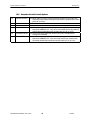
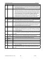
Revision Page
Date
11-07-01
11-07-01
11-09-01
11-09-01
Author
BWW
BWW
BWW
BWW
Description of Changes
Create REFRIG V8 manual from Chiller Manual 3.0 SWV8 & hdw v1.5.doc
Removed Control Zone documentation – this logic is not supported in Ref V8.
Added documentation for Defrost states & setpoints
Added documentation for Dehumidification mode
MCS-8 REFRIG V8 MANUAL REV 1.0.DOC
2
11/07/01
MICRO CONTROL SYSTEMS
2.
REVISION 1.0
Table of Contents
1.
REVISION PAGE................................................................................................................................................................2
2.
TABLE OF CONTENTS....................................................................................................................................................3
3.
INTRODUCTION ...............................................................................................................................................................6
3.1.
ABOUT MCS’S REF V8 SOFTWARE SUPPORT..............................................................................................................6
3.2.
ABOUT MCS’S CHL V8 HARDWARE SUPPORT ...........................................................................................................6
3.3.
ABOUT THIS MANUAL ....................................................................................................................................................6
3.4.
ABOUT THE MCS-8........................................................................................................................................................6
3.5.
ABOUT PC SUPPORT SOFTWARE FOR MCS-8...............................................................................................................7
3.6.
MCS 485 NETWORK ......................................................................................................................................................7
MCS 485 Network Local PC Support Only ..........................................................................................................................8
MCS 485 NETWORK REMOTE PC SUPPORT ONLY .....................................................................................................9
4.
REQUIREMENTS FOR PC SOFTWARE...................................................................................................................10
5.
MCS-8 CONTROL STATES...........................................................................................................................................11
5.1.
5.2.
CONTROL STATUS DISPLAY (FROM THE MCS-8 KEYPAD) .........................................................................................11
CONTROL STATUS DISPLAY (FROM THE PC-CONNECT PROGRAM)............................................................................13
6.
MCS-8 CAPACITY CONTROL STATES....................................................................................................................16
7.
MCS-8 CAPACITY CONTROL STATES SEQUENCE OF OPERATIONS........................................................18
8.
MCS-8 CIRCUIT CONTROL STATES........................................................................................................................19
9.
MCS-8 CIRCUIT CONTROL STATES SEQUENCE OF OPERATIONS............................................................22
10.
MCS-8 VOLTAGE SI CAPACITY CONTROL LOGIC ......................................................................................23
10.1.
VOLTAGE SI CONTROL METHOD SETPOINTS #1-18 ...............................................................................................23
10.2.
COMMON DEFINITIONS ............................................................................................................................................23
10.2.1. Targets, Stage Cut In Values..............................................................................................................................23
10.2.2. Stage Cut Out Values..........................................................................................................................................23
10.2.3. Step Delay............................................................................................................................................................23
10.2.4. Controlling Sensor..............................................................................................................................................23
11.
MCS-8 DEHUMIDIFICATION CONTROL LOGIC............................................................................................24
12.
MCS-8 DEFROST CONTROL LOGIC....................................................................................................................25
12.1.
12.2.
12.3.
12.4.
13.
13.1.
13.2.
13.3.
13.4.
14.
14.1.
DEFROST INTRODUCTION ........................................................................................................................................25
DEFROST SETPOINTS ................................................................................................................................................25
COOLING MODE DEFROST CYCLE ...........................................................................................................................25
DEHUMIDIFICATION MODE DEFROST CYCLE ..........................................................................................................26
MCS-8 CONDENSER CONTROL LOGIC.............................................................................................................27
CONDENSER INTRODUCTION ...................................................................................................................................27
RO STEP CONDENSER CUT IN – OUT LOGIC ..........................................................................................................27
RO STEP CONDENSER WITH VARIABLE SPEED FAN ..............................................................................................28
MODULATING CONDENSER .....................................................................................................................................28
MCS-8 SET POINT DEFINITIONS..........................................................................................................................29
SET POINT ELEMENTS THAT CAN BE VIEWED:..........................................................................................................29
MCS-8 REFRIG V8 MANUAL REV 1.0.DOC
3
11/07/01
MICRO CONTROL SYSTEMS
REVISION 1.0
14.2.
SET POINT TYPES:.....................................................................................................................................................29
14.2.1. SETPOINT...........................................................................................................................................................29
14.2.2. LOCKOUT ..........................................................................................................................................................29
14.2.3. ALARM................................................................................................................................................................29
15.
MCS-8 SET POINTS ....................................................................................................................................................30
15.1.
15.2.
15.3.
15.4.
15.5.
15.6.
15.7.
VOLTAGE SI CONTROL METHOD SETPOINTS #1-18 ...............................................................................................30
SETPOINTS FOR UNIT CONTROL OPTIONS ...............................................................................................................31
SETPOINTS FOR CONDENSER CONTROL ..................................................................................................................32
SETPOINTS FOR COMPRESSOR CONTROL ................................................................................................................33
SETPOINTS FOR COMPRESSOR SAFETIES .................................................................................................................34
SETPOINTS FOR UNIT SAFETIES................................................................................................................................36
SETPOINTS FOR DEFROST.........................................................................................................................................37
16.
MCS-8 AUTHORIZATION FUNCTION.................................................................................................................38
17.
MCS-8 STANDARD CONTROL OPTIONS ...........................................................................................................39
17.1.
17.2.
17.3.
17.4.
17.5.
17.6.
17.7.
17.8.
17.9.
17.10.
17.11.
17.12.
17.13.
17.14.
17.15.
18.
MCS-8 ALARMS AND SAFETIES ...........................................................................................................................44
18.1.
18.2.
18.2.1.
18.2.2.
18.2.3.
18.3.
18.3.1.
18.4.
18.4.1.
18.4.2.
18.4.3.
19.
19.1.
19.2.
20.
20.1.
GENERAL OPTIONS...................................................................................................................................................39
COMPRESSOR OPTIONS ............................................................................................................................................39
CONDENSER OPTIONS ..............................................................................................................................................39
UNIT BARREL HEATER OPTIONS .............................................................................................................................40
HOT GAS BYPASS.....................................................................................................................................................40
ON/OFF SWITCHES ...................................................................................................................................................40
LOW SUCTION HOLDING .........................................................................................................................................40
HIGH DISCHARGE PRESSURE HOLDING...................................................................................................................41
HIGH DISCHARGE TEMPERATURE HOLDING...........................................................................................................41
HIGH AMPERE HOLDING..........................................................................................................................................41
CONTROL POWER RELAY –NO STOP.......................................................................................................................41
PART WIND OR STAR DELTA STARTER ...................................................................................................................42
LOW & HIGH AMBIENT SHUTDOWN .......................................................................................................................42
ENGLISH OR METRIC SENSOR READINGS .................................................................................................................42
COMPRESSOR AUTO ROTATION ..............................................................................................................................42
INTRODUCTION.........................................................................................................................................................44
INFORMATION ONLY ALARMS ..................................................................................................................................44
System generated alarms....................................................................................................................................44
Alarms as a result of individual action ..............................................................................................................44
Alarms generated by the control algorithm.......................................................................................................44
MCS-8 SYSTEM ALARMS .........................................................................................................................................45
Alarms are generated by the MCS-8 control algorithm:..................................................................................45
SET POINT SAFETY ALARMS. ....................................................................................................................................46
Introduction.........................................................................................................................................................46
Sensor inputs used in conjunction with MCS-8 set point safeties: ...................................................................46
Set point safeties..................................................................................................................................................47
MCS-8 OEM FACTORY CHECKOUT PROCEDURE .......................................................................................50
VISUAL CHECK.........................................................................................................................................................50
MCS POWER ON (COMPRESSOR POWER OFF) .......................................................................................................50
MCS-8 COMPRESSOR RELAY OUTPUT SEQUENCE (EXAMPLES) .........................................................51
RECIPROCATING COMPRESSOR...............................................................................................................................51
21.
MCS-8 KEYPAD/DISPLAY QUICK REFERENCE- STATUS KEYS................................................................52
22.
MCS-8 KEYPAD/DISPLAY QUICK REFERENCE-ENTRY KEYS..................................................................53
MCS-8 REFRIG V8 MANUAL REV 1.0.DOC
4
11/07/01
MICRO CONTROL SYSTEMS
REVISION 1.0
23.
MCS-8 & I/O QUICK REFERENCE SHEET .........................................................................................................54
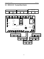
24.
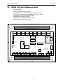
MCS-8 & I/O – TERMINAL BLOCK DETAILS ...................................................................................................55
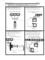
25.
MCS-8 SENSORS QUICK REFERENCE SHEET– TEMP./HUMD. SENSORS ............................................56
26.
MCS-8 SENSORS QUICK REFERENCE SHEET - PRESSURE SENSOR & DIGITAL INPUTS .............57
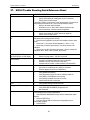
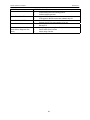
27.
MCS-8 TROUBLE SHOOTING QUICK REFERENCE SHEET.......................................................................58
MCS-8 REFRIG V8 MANUAL REV 1.0.DOC
5
11/07/01
MICRO CONTROL SYSTEMS
3.
REVISION 1.0
Introduction
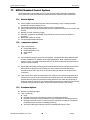
3.1.
About MCS’s REF V8 Software Support
The REF V8 software, “REF R08.00-B” or greater supports:
Up to 8 reciprocating, and or scroll compressors,
Up to 4 steps of capacity control per compressor (3 unloaders),
Relay Outputs up to 48,
Analog Outputs up to 6,
Sensor Inputs up to 48,
Set Points up to 120,
Alarms up to 60.
REF R08.00-B software supports fixed step capacity systems. This includes support for
reciprocating, scroll and screw compressors that do not have infinite slide control. This software
must not be used with screw compressors that have infinite slide control.
3.2.
About MCS’s CHL V8 Hardware Support
The following MCS boards can be connected via the MCS-I/O network:
MCS-8 (8 RO - 8 SI - 1 AO with REF R8.00-B with a GAL 6.0 chip),
MCS-I/O (8 RO - 8 SI - 1 AO with IO 7.00-C with a GAL 5.0 chip),
MCS-RO8 (8 RO),
MCS-SI8 (8 SI),
MCS-SI16.(16 SI).
This provides flexibility in configuring the individual systems to obtain the desired number of points
in the most economical way.
3.3.
About this Manual
The purpose of this manual is to document MCS’s REF V8 software for the MCS-8.
This manual documents how the REF V8 software functions. Since this is a large manual, it is
structured in logical sections for ease of reference. The Table of Contents will guide you through
the sections but you are urged to read the entire manual. This will provide an understanding of the
capabilities of the MCS-8 and hopefully introduce other ways that you may benefit from the existing
control strategies. Quick Reference sheets and MCS Specification sheets are provided in the
appendixes.
This manual was created using Microsoft Office, Word 97. A copy of this manual is available on
diskette.
An approved OEM of MCS may make copies and / or change any section of this manual to
develop custom documentation for a site where an MCS-8 controller is installed. In this way, MCS
supports the documentation requirements of individual customer sites.
3.4.
About the MCS-8
The MCS-8 is a rugged microprocessor based controller that is designed for the hostile
environment of the HVAC/R industry. It is designed to provide primary control, no mechanical
controls; interface with building management systems; communicate both locally and remotely. The
MCS-8 provides flexibility with set points and control options that can be selected prior to
commissioning a system or when the unit is live and functioning. Displays, alarms and other
interfaces are accomplished in a clear and simple language that informs the user as to the status of
the controller.
MCS-8 REFRIG V8 MANUAL REV 1.0.DOC
6
11/07/01
MICRO CONTROL SYSTEMS
REVISION 1.0
The MCS-8 is designed to safeguard the system that is being controlled, eliminate the need for
manual intervention and to provide a simple but meaningful man-machine-interface.
3.5.
About PC Support Software for MCS-8
!
PC-Config program provides the configuration file: points list, set points, options, etc. This
program is user friendly with English questions and drop down menus. It is written in the
Microsoft Visual Basic programming language. A manual created under Microsoft Office, Word
97, for Windows 95 is available on disk or hard copy.
!
PC-Connect program provides both local and remote communications to the MCS-8
independent of the type of software. Through this program the status of the controller can be
viewed and with proper authorization changes can be made to the system. Configuration files
can be transmitted to or received from an MCS-8 unit. The MCS-8 automatically performs
history logging; this program will graph selected items. This program is written in the Microsoft
Visual C++ programming language. A general user’s manual is available with this software
package.
Both of these programs run under Windows 3.1 or greater and they make use of the Microsoft
Windows Help function to assist the user.
3.6.
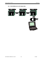
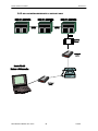
MCS 485 Network
The MCS 485 Network can support up to 20 MCS-8 and its associated I/O’s. Access to this
network can be local or remote via a 14.4K Baud modem. There will be no degradation in the
performance of the network. The PC connected to the network must be running Windows 3.1 or
higher with PC-Connect providing the actual interface program.
Each MCS-8 in the network must be assigned a unique address when the configuration file is build
using the PC-Config program. This address will be the key in establishing communications with the
appropriate MCS-8 system. This address can be changed from the LCD / keypad of a unit.
MCS-8 REFRIG V8 MANUAL REV 1.0.DOC
7
11/07/01
MICRO CONTROL SYSTEMS
REVISION 1.0
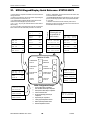
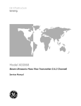
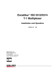
3.6.1. MCS 485 Network Local PC Support Only
MCS-8 REFRIG V8 MANUAL REV 1.0.DOC
8
11/07/01
MICRO CONTROL SYSTEMS
REVISION 1.0
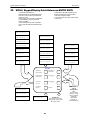
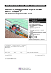
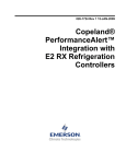
3.6.2. MCS 485 NETWORK REMOTE PC SUPPORT ONLY
MCS-8 REFRIG V8 MANUAL REV 1.0.DOC
9
11/07/01
MICRO CONTROL SYSTEMS
4.
REVISION 1.0
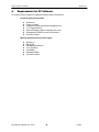
Requirements for PC Software
To install and run the program we suggest the following system requirements:
Front End System Requirements
!
!
!
!
!
!
!
Windows 95
Pentium 166 MHz
2 Gigabyte hard disk with at least 25 Megabytes free
3 ½ “ Floppy Disk Drive
Super VGA display capable of displaying 256 colors
16 Megabytes of RAM or more is recommended
33.6k baud modem
Minimum System Required to Run Program
!
!
!
!
!
!
!
Windows 3.1
486 66 MHz
500 Megabyte Hard Drive
3½” Floppy Drive
VGA Display
8 Megabytes RAM
14.4k baud modem
MCS-8 REFRIG V8 MANUAL REV 1.0.DOC
10
11/07/01
MICRO CONTROL SYSTEMS
5.
REVISION 1.0
MCS-8 Control States
We should consider the MCS-8 controller as a state computer, that is, decisions are made based
upon set points, timers and sensor inputs, the controller moves from one state to another. The
controller will change states to ensure the proper functioning of the unit.
As we review the various states, we must remember that a unit consists of a number of different
parts or functions: the compressors and their related items such as unloaders hot gas bypasses,
etc.; evaporator; and condensing functions. To control these functions the states will be divided
into three sections:
!
!
!
Capacity Control States
Circuit Control States
Condenser Control States
Both the CAPACITY CONTROL STATES and CIRCUIT CONTROL STATES are displayed on the
2x16 LCD. Press the SERVICE DIAGNOSTICS key until the option is the CONTROL STATUS,
then press the ENTER key. The INCREASE and DECREASE keys can be used to scroll through
the various state screens. Or it can be accessed via the PC-Connect program under status screen
by clicking on the CONTROL STATUS button.
5.1.
Control Status Display (from the MCS-8 keypad)
The following will be displayed:
A. The CURRENT STATE OF THE PACKAGE.
st
The 1 display shows the current capacity of the package and how long we have been at this
level.
Line 1) UNIT IS UNLOADED
Line 2) TIMER=00:02:14
By pressing the + key you will get information on the accumulator. (Starts with the value in the
set point ‘STEP DELAY’ and decrements down as a function of the difference between the
target and the current value of the controlling sensor. (Usually leaving liquid). The second line
provides the Rate of Change of the controlling sensor.
Line 1) STEP DELAY=180
Line 2) RATE OF CHG+ 0.0
By pressing the + key you will get information on the number of steps wanted on and the actual
number of steps on. (They may be different if the system is waiting on a unit in safety or anti
recycle.).
Line 1) STEPS WANTED=
Line 2) ACTUAL STEPS=
0
0
If a infinite step compressor package: by pressing the + key you will get information on the % of
FLA the screw wants to be loaded
Line 1) SLIDE WANTED= 48
Line 2)
MCS-8 REFRIG V8 MANUAL REV 1.0.DOC
11
11/07/01
MICRO CONTROL SYSTEMS
REVISION 1.0
B. The CURRENT STATE OF EACH CIRCUIT
The display will show the circuit number, current state of this circuit, if available the FLA % and the
time in this state. (An arrow will appear immediately after the circuit number to indicate the lead
compressor.) This information will be repeated per circuit. CHL V8 software supports up to 8
circuits.
Line 1) 1←CMP IS OFF
Line 2) 48%FLA 00:22:12
MCS-8 REFRIG V8 MANUAL REV 1.0.DOC
12
11/07/01
MICRO CONTROL SYSTEMS
5.2.
REVISION 1.0
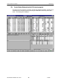
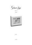
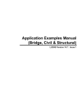
Control Status Display (from the PC-Connect program)
The status of both the CAPACITY CONTROL STATES and CIRCUIT CONTROL STATES can be
viewed from the PC-Connect program by accessing the CONTROL STATUS key under status
screen. The following will be displayed:
MCS-8 REFRIG V8 MANUAL REV 1.0.DOC
13
11/07/01
MICRO CONTROL SYSTEMS
REVISION 1.0
Use your arrow keys to access all information (Active circuits will be displayed)
Information displayed:
Unit information:
• CAPACITY CONTROL STATE - State of unit
• TIME - time in that state, if the state is UNIT IN POWER UP time will decrement to zero
• STEPS WANTD (ON) - Number of steps wanted on
• ACTUAL - actual steps turned on
• STEP DELAY – time delay that is counted down. When the value reaches zero, the micro
•
•
will determine if a change in the unit’s capacity is required.
WANTED SLIDE % - Wanted slide percentage
RATE OF CHNG – Rate of Change of supply air temperature.
Circuit information (all active circuits will be displayed):
• CIRCUIT NUMBER AND STATE - Circuit number and state.
• TIME - time in that state, if the state is CMP ANTICYCLE time will decrement to zero.
•
•
OIL DIFF - Oil differential pressure. Oil differential pressure is calculated as follows:
Oil pressure minus Suction pressure
LEAD - (") indicates the lead compressor.
STEPS – number of steps on or FLA %.
Circuit Super Heat information (all active circuits will be displayed):
• Suction Temp – Circuit number and current valve of the Suction Temperature, if available.
• Saturated Suction– Calculated Suction Saturated Temperature, if available. The Suction
•
•
•
•
Pressure is converted into temperature based upon the type of refrigerant (R22, R134a,
R407c, And R410a are supported).
Suction SuperHt – Calculated Suction Super Heat, only available if both the Suction
Temperature and the Suction Pressure are used. The calculation is Suction Temperature
minus the Suction Saturated Temperature.
Disc Temp – Discharge Temperature, if available.
Saturated Discharge– Calculated Discharge Saturated Temperature, if available. The
Discharge Pressure is converted into temperature based upon the type of refrigerant (R22,
R134a, R407c, And R410a are supported).
Disc SuperHt – Calculated Discharge Super Heat, only available if both the Discharge
Temperature and the Discharge Pressure are used. The calculation is Discharge
Temperature minus the Discharge Saturated Temperature.
MCS-8 REFRIG V8 MANUAL REV 1.0.DOC
14
11/07/01
MICRO CONTROL SYSTEMS
MCS-8 REFRIG V8 MANUAL REV 1.0.DOC
REVISION 1.0
15
11/07/01
MICRO CONTROL SYSTEMS
6.
REVISION 1.0
MCS-8 Capacity Control States
UNIT IN POWER UP
This state is entered when the MCS-8 is powered up or the system has been reset. The system will
remain in this state for the time specified in set point POWER DELAY, set point 23, or if not active
for 60 seconds. In this state all points (RO’s) are turned off. This is a time delay to insure the micro
has stable power before turning any points on.
RUN/STOP SW OFF
This state is entered when the run stop switch is off, in the stop position. When the unit is in this
state, the individual circuit states if active are moved to the CMP IS OFF state through the normal
states. One capacity STEP will be moved per second.
SCHEDULED OFF
This state is entered when the schedule is calling for the package to be off. When the unit is in this
state, the individual circuit states if active are moved to the CMP IS OFF state through the normal
states. One capacity STEP will be moved per second.
AMBIENT OFF
This state is entered when the ambient temperature falls below the LOW AMB OFF set point #24
or is above the HIGH AMB OFF set point #26. System will remain in this state until the ambient
temperature if low raises 5.0F or 2.5C degrees above the LOW AMB OFF set point value or if high
drops 5.0F or 2.5C degrees below the HIGH AMB OFF set point value. When the unit is in this
state, the individual circuit states if active are moved to the CMP IS OFF state through the normal
staging function. One capacity STEP will be moved per second.
UNIT IN LOCKOUT
This state is entered whenever a critical situation is encountered that could cause harm to the unit
package. Items such as freeze protect, no flow and emergency stop will force the system into this
state. Lockouts can be reset without authorization from the keypad or PC-Connect program;
however if the lockout condition has not been corrected, the system will again be forced into the
LOCKOUT state. In this state, all RO’s except ALARM RO and the oil heater RO for screws with
and oil pump are turned OFF & placed in the ‘LOCKOUT’ state.
NO RUN- I/O LOST
This state will be entered whenever the MCS-8 loses communications with any of the I/O boards
that are connected via the MCS I/O network. When this state is entered the system will generate an
MCS I/O alarm which identifies which I/O is off-line and a lost IO shutdown alarm. The lockoutreset key must be depressed to reset the system, after the lost I/O has been corrected. In this
state, all RO’s except ALARM RO are turned OFF.
UNIT IS OFF
This state is entered when the system has moved from a STARTUP, DISABLE, LOCKOUT or
LOST I/O state. The unit is now ready to move into an active state to meet the capacity required.
UNIT IS HOLDING
This state is entered when one of three conditions exists:
1) The control sensor reading is being maintained with in the control zone.
MCS-8 REFRIG V8 MANUAL REV 1.0.DOC
16
11/07/01
MICRO CONTROL SYSTEMS
REVISION 1.0
2) Control sensor reading is above the control zone but the Rate of Change is less than the
value in the (MAX ROC-, #27) set point. This indicates that the temperature is decreasing
toward the target at an acceptable speed. Therefore, no additional cooling is needed at this
time.
3) The temperature is below the control zone but the Rate of Change is greater than the
(MAX ROC+, #28) set point. This indicates that the temperature is increasing toward the
target. Therefore, no reduction in cooling is needed at this time.
This state indicates that there is no need to add or subtract the cooling capacity of the unit. This
state will be exited when more or less capacity is required.
UNIT UNLOADING
This state is entered when less capacity is required. Every second an adjustment is made to the
step delay. When the delay reaches zero, the counter ‘steps wanted’ on is decreased by 1.
UNIT IS LOADING
This state is entered when more capacity is required. Every second an adjustment is made to the
step delay. When the delay reaches zero, the counter ‘steps wanted on’ is increased by 1.
UNIT IS UNLOADED
This state is entered when all of the systems available capacity steps are off. The package is
providing no cooling capacity, as none is required. The system is ready to react to cooling needs.
UNIT IS LOADED
This state is entered when all of the systems available capacity steps are on. The package is
providing the maximum amount of cooling capacity.
MCS-8 REFRIG V8 MANUAL REV 1.0.DOC
17
11/07/01
MICRO CONTROL SYSTEMS
7.
REVISION 1.0
MCS-8 Capacity Control States Sequence of Operations
After power is applied to the MCS-8 the following is the normal sequence of Capacity control States:
1. Unit in Power Up
2. Run/Stop SW OFF
• If the Run/Stop switch is turn ON then the remain states sequence occurs.
3. Unit is Unloaded
4. Unit is Loading or Unit is Holding or Unit is Unloading
• The micro will move between these three states as required by the voltage sensor input
until Run/Stop switch is turned off. Once the Run/Stop switch is turned of the capacity
control state will move to Unit is Unloading until Steps Wanted On equals zero. Then it will
go back to Run/Stop SW OFF.
MCS-8 REFRIG V8 MANUAL REV 1.0.DOC
18
11/07/01
MICRO CONTROL SYSTEMS
8.
REVISION 1.0
MCS-8 Circuit Control States
The action of the circuit control states actually result in more, less or no change in the amount of
cooling capacity. The CAPACITY CONTROL STATES dictate how the individual circuits move
within there states.
CMP IS OFF
This state is entered when no cooling capacity is required from this circuit or the prior state was
CMP ANTICYCE, LOST IO LOCKED or SWITCHED OFF. In this state the circuit is ready to
provide cooling capacity if needed. The system will remain for a minimum delay of 60 seconds in
this state.
HI DISC HOLD
Refer to set points numbers 81, HI DISCH PSI; 82, HI DISC UNLD; 83, HI DISC RELD; 87, HI
DISCH TMP; 88, HI DISCH UNLD; and 89, HI DISCH RELD.
This state is entered when a fully loaded circuit, that has more than one step, has encountered
either a dangerously high discharge pressure or discharge temperature. One step of cooling
capacity will be turned off. The circuit will remain in this state for a minimum of five minutes before
returning to the LOADED state if the dangerous condition has been corrected.
LO SUCT HOLD
Refer to set points numbers 77, LOW SUCTION; 78, LO SUCT UNLD; and 79, LO SUCT RELD.
This state is entered when a fully loaded circuit, that has more than one step, has encountered a
dangerously low suction pressure. One step of cooling capacity will be turned off. The circuit will
remain in this state for a minimum of five minutes before returning to the LOADED state if the
dangerous condition has been corrected.
CMP UNLOADED
This state only exists if a compressor has an unloader or Hot Gas Bypass solenoid. This state is
when the minimum capacity is required from the compressor. In this state the compressor, liquid
line solenoids, all unloaders, Hot Gas Bypass solenoid, and Differential Pressure regulating valve
are ON and Hot Gas Defrost solenoids are OFF.
UNLD1/HGBP OFF
This state can only be entered for compressors with a HOT GAS BYPASS solenoid. In this state
the HOT GAS BYPASS solenoid is off and all unloaders in the circuit are on.
PART LOADED
This state only exists if a compressor has two unloaders. This state is when the HOT GAS
BYPASS solenoid, if it exists, is off, the first unloader solenoid is off and the second unloader
solenoid is on.
CMP IS AT 100%
This state is when the compressor is fully loaded. In this state, the circuit is providing the maximum
amount of cooling capacity. In this state the compressor, liquid line solenoids, and Differential
Pressure regulating valve are ON and all unloaders, Hot Gas Bypass solenoid, and Hot Gas
Defrost solenoids are OFF.
MCS-8 REFRIG V8 MANUAL REV 1.0.DOC
19
11/07/01
MICRO CONTROL SYSTEMS
REVISION 1.0
CMP PMP DOWN
This state is entered whenever the pump down switch has been turned on or if this circuit is no
longer wanted on. The compressor is on and the liquid line solenoids are closed. This state is
active until the suction pressure reaches the value in the set point 61; PMP DWN OFF or the time
has exceeded the value in the set point 62, PMP DWN DELY. The circuit will then move to the
ANTICYC state.
CMP ANTICYCE
This state is entered when the PMP DWN state has been completed. The circuit will stay in this
state with all circuit points off for the period of time contained in set point 63, ANTI-CYCLE. The
circuit will then move to the OFF state.
SWITCHED OFF
This state is entered after the circuit has been pumped down due to the pump down switch being
on or if the circuit flow switch is off. In this state the compressor, and all related points, plus the
liquid line are off. The circuit will not leave this state unless the pump down switch is turned off. If
the pump down switch is turned off, the circuit state will be changed to the OFF state.
SAFETY TRIPPED
This state is entered when a safety trips but a lockout is not to be generated. An alarm is
generated but the system will restart after the delay specified in the corresponding set point. If a
second trip occurs within the time specified in the set point, the circuit will be placed in the CMP
LOCK EDOUT state.
CMP LOCKED OUT
This state is entered when the Capacity Control State is LOCK OUT or a safety set point for this
circuit has indicated that a critical situation has been encountered. Set points such as (LOW
SUCTION #77) or (HI DISCH PSI #81) are examples of safety set points. Lockouts can be reset
without authorization from the keypad or PC-Connect program; however if the lockout condition has
not been corrected, the circuit will again be forced into the LOCKOUT state.
LOST IO LOCKED
This state is entered when the Capacity Control State is LOST IO. Lockout reset key will move the
circuit to the OFF state. Lockouts can be reset without authorization from the keypad or PCConnect program; however if the lockout condition has not been corrected, the circuit will again be
forced into the LOCKOUT state.
HI AMP HOLD
This state is entered when a fully loaded circuit, that has more than one step, has encountered a
dangerously high AMP draw. Refer to set points numbers 65 through 72 for FLA per circuit and 75
HI AMPS %. In this state, one step of cooling capacity will be turned off. The circuit will remain in
this state for a minimum of five minutes before returning to the LOADED state if the dangerous
condition has been corrected.
DEFROST EVAP#1
This state is entered when the evaporator pressure falls below a setpoint for 60 second indicating a
need to defrost the evaporator coils. In this state the compressor, liquid line solenoid #2, and
MCS-8 REFRIG V8 MANUAL REV 1.0.DOC
20
11/07/01
MICRO CONTROL SYSTEMS
REVISION 1.0
defrost hot gas #1 solenoid are ON and liquid line solenoid #1, defrost hot gas solenoid #2,
differential pressure regulating value, and the drain solenoid are OFF.
DRIP DOWN #1
This state is entered after evaporator #1 has finished it’s hot gas defrost. This is a time delay to
allow the water to drip down off the defrosted coil before turning back on the liquid line solenoid. In
this state the compressor, and liquid line solenoid #2 are ON and liquid line solenoid #1, defrost hot
gas #1 solenoid, defrost hot gas solenoid #2, differential pressure regulating value, and the drain
solenoid are OFF.
DEFROST EVAP#2
This state is entered after the defrost cycle for evaporator #1 has finished it’s cycle. In this state the
compressor, liquid line solenoid #1, and defrost hot gas #2 solenoid are ON and liquid line solenoid
#2, defrost hot gas solenoid #1, differential pressure regulating value, and the drain solenoid are
OFF.
DRIP DOWN #2
This state is entered after evaporator #2 has finished it’s hot gas defrost. This is a time delay to
allow the water to drip down off the defrosted coil before turning back on the liquid line solenoid. In
this state the compressor, and liquid line solenoid #1 are ON and liquid line solenoid #2, defrost hot
gas #1 solenoid, defrost hot gas solenoid #2, differential pressure regulating value, and the drain
solenoid are OFF.
MCS-8 REFRIG V8 MANUAL REV 1.0.DOC
21
11/07/01
MICRO CONTROL SYSTEMS
9.
REVISION 1.0
MCS-8 Circuit Control States Sequence of Operations
After power is applied to the MCS-8 the following is the normal sequence of Capacity control States:
1. CMP IS OFF
• If steps wanted on is greater than steps turned on then the remaining states occur.
2. CMP IS AT 100% - If defrost required then state move through the defrost cycle.
• If steps wanted on is less steps turned on or Pump Down Switch is turned on then the
remaining steps occur.
3. CMP PMP DOWN
4. CMP ANTICYCLE
MCS-8 REFRIG V8 MANUAL REV 1.0.DOC
22
11/07/01
MICRO CONTROL SYSTEMS
REVISION 1.0
10. MCS-8 Voltage SI Capacity Control Logic
This control strategy is based upon developing a series of cut in (turn on) and cut out (turn off) values
for each capacity stage (step) in the system. When a cut in value has been reached or exceeded and
the delay time between stages (steps) has been satisfied, the micro will turn on the next stage (step).
Conversely, when a cut out value has been reached and the delay time between stages (steps) has
been satisfied, the micro will turn off the last stage (step) that was turned on.
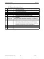
10.1. Voltage SI Control Method setpoints #1-18
#
1
2
NAME
STAGE DELAY
STAGE CUT OUT
3
4
5
6
7
8
9
10
11
12
13
14
15
16
17
18
STAGE 1 CUT IN
STAGE 2 CUT IN
STAGE 3 CUT IN
STAGE 4 CUT IN
STAGE 5 CUT IN
STAGE 6 CUT IN
STAGE 7 CUT IN
STAGE 8 CUT IN
STAGE 9 CUT IN
STAGE 10 CUT IN
STAGE 11 CUT IN
STAGE 12 CUT IN
STAGE 13 CUT IN
STAGE 14 CUT IN
STAGE 15 CUT IN
STAGE 16 CUT IN
DESCRIPTION
Delay between stages being turned on.
Off set used in calculating the cut out value. Subtracted from the stage cut in set
points #3 through #18
STAGE 1 cut in, set point value contains the value when this stage is turned on.
STAGE 2 cut in, set point value contains the value when this stage is turned on.
STAGE 3 cut in, set point value contains the value when this stage is turned on.
STAGE 4 cut in, set point value contains the value when this stage is turned on.
STAGE 5 cut in, set point value contains the value when this stage is turned on.
STAGE 6 cut in, set point value contains the value when this stage is turned on.
STAGE 7 cut in, set point value contains the value when this stage is turned on.
STAGE 8 cut in, set point value contains the value when this stage is turned on.
STAGE 9 cut in, set point value contains the value when this stage is turned on.
STAGE 10 cut in, set point value contains the value when this stage is turned on.
STAGE 11 cut in, set point value contains the value when this stage is turned on.
STAGE 12 cut in, set point value contains the value when this stage is turned on.
STAGE 13 cut in, set point value contains the value when this stage is turned on.
STAGE 14 cut in, set point value contains the value when this stage is turned on.
STAGE 15 cut in, set point value contains the value when this stage is turned on.
STAGE 16 cut in, set point value contains the value when this stage is turned on.
10.2. Common Definitions
10.2.1. Targets, Stage Cut In Values
The control targets, stage cut in values, for up to 16 steps of capacity are specified in set points 3
through 18.
10.2.2. Stage Cut Out Values
The stage cut out values for each step of capacity is calculated by subtracting set point 2 from the
individual step cut in value.
10.2.3. Step Delay
The step delay is contained in set point 1. This is the minimum time between changes in capacity.
10.2.4. Controlling Sensor
This is the sensor that has been specified in the PC-Config program as providing the control value. It
will normally be either a voltage that is being provided by an external system, entering or leaving
temperature or the suction pressure. The set points must be adjusted to agree with the controlling
value.
MCS-8 REFRIG V8 MANUAL REV 1.0.DOC
23
11/07/01
MICRO CONTROL SYSTEMS
REVISION 1.0
11. MCS-8 Dehumidification Control Logic
Unit defaults to Cooling mode, however the system can be forced into Dehumidification mode by a
digital input. The MCS-8 CFG must be setup to have a DEHUMIDIFICATION ENABLE input. When
this input is ON the Unit is forced into Dehumidification mode. When the unit is in Dehumidification
mode only one of the two evaporators is needed. This means that the second liquid line solenoid is
OFF when in Dehumidification mode. While in Dehumidification mode the capacity control is still using
the voltage input sensor to determine how many compressors, unloaders are required to run.
MCS-8 REFRIG V8 MANUAL REV 1.0.DOC
24
11/07/01
MICRO CONTROL SYSTEMS
REVISION 1.0
12. MCS-8 Defrost Control Logic
12.1. Defrost Introduction
The MCS-8 REFRIG V8 software incorporates an intelligent defrost control algorithm, that is to say it
does not use fixed schedules for defrosting the evaporator coils. The defrost cycle is driven based on
two sensors, the supply air temperature and the evaporator pressure. This way the defrost cycle is
started as soon an evaporator ‘s coil is iced over and is no longer efficient. Also defrost cycle are only
perform when an evaporator coil is iced over, thus eliminating unneeded defrost cycles. The MCS-8
allow for three duration based on type of defrost HI TEMP, MED TEMP, LO TEMP.
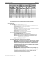
12.2. Defrost Setpoints
The actual supply temperature determines which type of defrost occurs. The following chart shows
how the micro determines which type of defrost:
Type of Defrost
High Temp – If actual supply temp > setpoint
#101 DEF-HI TEMP
Med Temp – if actual supply temp >
setpoint#102 DEF-MED TEMP
Low Temp – if actual supply temp <=
setpoint#102 DEF-MED TEMP
Evaporator
Pressure
Setpoint #113
DEF-HI PSI
Setpoint #115
DEF-MED PSI
Setpoint #117
DEF-LO PSI
Defrost Time
Setpoint #114
DEF-HI TIME
Setpoint #116
DEF-MED TIME
Setpoint #118
DEF-LOW TIME
Based on the type of defrost the logic changes when the defrost starts and for how long it occurs. The
micro compares the evaporator pressure to the evaporator setpoint determined by the type of defrost.
12.3. Cooling mode Defrost Cycle
The defrost logic controls each circuit/compressor independently. When the circuit’s evaporator
pressure is less than the setpoint for 60 seconds and the number of circuits in defrost is less than the
MAX DEF EVAP setpoint #109 the defrost cycle is started for the circuit only. A defrost cycle consist of
the following:
1. Place evaporator #1 in hot gas defrost for x minutes while using evaporator #2 for
refrigeration, then
2. Drip down evaporator #1 for 2 minutes (setpoint #110 DRIP DOWN) while using
evaporator #2 for refrigeration, then
3. Place evaporator #2 in hot gas defrost for x minutes while using evaporator #1 for
refrigeration, then
4. Drip down evaporator #2 for 2 minutes (setpoint #110 DRIP DOWN) while using
evaporator #1 for refrigeration.
Once a defrost cycle has been performed that circuit is not allowed to perform an another defrost cycle
for the minimum of five minutes.
Once a defrost cycle has been started by any circuit the type of defrost for all circuit is locked until 10
minutes (setpoint #90 DEF TMP LOCK) after the defrost has completed. This prevents the heat being
add by the defrost from changing the type of defrost perform by the other circuits.
MCS-8 REFRIG V8 MANUAL REV 1.0.DOC
25
11/07/01
MICRO CONTROL SYSTEMS
REVISION 1.0
12.4. Dehumidification mode Defrost Cycle
The defrost cycle when in dehumidification mode is the same as the cooling mode defrost cycle. There
are only two different:
1. The evaporator pressure setpoint for starting the defrost does not change, it always looks to see if
the evaporator pressure is less than setpoint #119 DEF-DEHUM to start a defrost cycles
2. The defrost time duration does not change, it always using setpoint #118 DEF-LO TIME.
MCS-8 REFRIG V8 MANUAL REV 1.0.DOC
26
11/07/01
MICRO CONTROL SYSTEMS
REVISION 1.0
13. MCS-8 Condenser Control Logic
13.1. Condenser Introduction
Control of common condenser, individual condensers per circuit or condensers that are shared
between circuits are supported. The type of condenser plus the number of condenser points (RO’s)
are specified when building the configuration file. The system supports the following options:
1. No Condenser - No condenser specified.
2. RO Step Common
- If RO Step Common condenser is specified, the highest discharge
pressure from any one of the circuits on the system will be the controlling pressure.
3. RO Step Individual
- If RO Step Individual condenser is specified, then the discharge
pressure on that circuit will be the controlling pressure.
4. RO Step Combined
- If RO Step Combined condenser is specified, then the highest
discharge pressure from any one of the compressors on the shared circuits will be the
controlling pressure (circuits 1&2 are shared; circuits 3&4 are shared, circuits 5&6 are shared,
and circuits 7&8 are shared).
5. Modulating Common- If Modulating Common condenser is specified, the highest discharge
pressure from any one of the circuits on the system will be the controlling pressure. A change
to the modulating analog output position is calculated every 30 seconds based on the Rate of
Change of the controlling discharge pressure.
The system will also support a variable speed fan for all three of the air type of condensers. Each
circuit can support a variable speed fan.
13.2. RO Step Condenser Cut In – Out Logic
The air condenser set points are as follows:
Set point 45 CND STG1 ON
- Condenser stage 1 cut in (ON).
Set point 46 CND STG1 OFF
- Condenser stage 1 cut out (OFF).
Set point 47 CND DIFF ON
- Differential between condenser stages for cut in (ON).
Set point 48 CND DIFF OFF
- Differential between condenser stages for cut out (OFF).
Set point 49 CND MIN RUN
- Minimum run time for a condenser stage
Condenser points, (i.e. fans), will be turned on based upon the value in set point (COND ST1 ON)
#44, when the discharge pressure reaches this value the first condenser point is turned on. If
additional condenser points exist, they will be turned on when the pressure exceeds the previous
cut in value plus the value contained in (COND DIFF IN #47) set point. As the discharge pressure
is reduced, the condenser points be turned off based upon the set point (COND ST1 OFF #46)
value plus the condenser step times the value contained in (COND DIFF OUT #48) set point. The
first step will be turned off based upon the valve in the set point (COND ST1 OFF).
Example
Set point 45 CND STG1 ON
Set point 46 CND STG1 OFF
Set point 47 CND DIFF IN
Set point 48 CND DIFF OFF
= 180.0P
= 150.P
= 30.0P
= 15.0P
COND FAN1 ON @ 180.0 P DISCHARGE
COND FAN 1 OFF @ 150.0 P
COND FAN2 ON @ 210.0p (180.0 + 30.0)
COND FAN2 OFF @ 165.0p (150.0 +15.0)
COND FAN3 ON @ 240.0p (210.0 + 30.0)
COND FAN3 OFF @ 180.0p (165.0 + 15.0), etc.
MCS-8 REFRIG V8 MANUAL REV 1.0.DOC
27
11/07/01
MICRO CONTROL SYSTEMS
REVISION 1.0
13.3. RO Step Condenser With Variable Speed Fan
The set points for air condensers with for variable speed fan control are as follows:
Setpoint 54 CND MIN SPD
- Minimum variable speed allowed.
Setpoint 55 CND MAX SPD
- Maximum variable speed allowed.
The purpose of the variable speed fan is to reduce the cycling of the fans by adjusting the speed of
the variable fan point. This control works in conjunction with the cut in and cut out logic of each
circuit. The cut in and cut out logic turns on or off the various condenser fan points. When a fan is
turned on, the speed of the variable point for that circuit is set to minimum allowed percentage.
When a fan is turned off, the speed of the variable point is set to 75%.
Once a fan point has been turned on, the system will vary the fan speed for that circuit. This will be
based upon where the discharge pressure is in relationship to turning the current fan point off and
turning the next fan point on.
13.4. Modulating Condenser
The example is of a system with a water condenser. The water valve will be modulated.
The water condenser set points are as follows:
Set point 50 CND VLV TARG
- Discharge target pressure.
Set point 51 CND VLV DIV
- Condenser valve adjustment sensitivity.
Set point 52 CND VLV MIN
- Condenser valve minimum opening.
Set point 53 CND VLV ROC- Condenser max negative Rate of Change
Condenser water valve will be adjusted based upon the Rate of Change of the discharge pressure.
The logic is setup to modulate a water valve using the analog output (0 to 10vdc), to maintain the
discharge pressure (logic selects the highest discharge pressure from the running circuits).
Example
CND VLV TARG
CND VLV DIV
CND VLV MIN
CND VLV ROC-
MCS-8 REFRIG V8 MANUAL REV 1.0.DOC
=
=
=
=
28
190.0P
1
25%
-5.0P
11/07/01
MICRO CONTROL SYSTEMS
REVISION 1.0
14. MCS-8 Set Point Definitions
14.1. Set point elements that can be viewed:
1) Number - the number is from 1 to 120, maximum number of set points that are supported.
Only active set points will be displayed.
2) Name - the set point’s name consists of up to 12 alphanumeric characters. The name is
displayed following the number on the first line of the LCD display. The name of the set point
can be changed to make it meaningful to the given application. HOWEVER the function of the
set point will remain the same.
3) Value - this is the value or target of a set point. This value is displayed on the second line of the
LCD display. With the proper authorization this value can be changed within limits that have
been established by the PC-Config program.
4) Time - this is the time that the set point must be true before it will trip. E.g. a high discharge
safety must have its value exceeded for this length of time before it will trip. This time is always
in seconds and it is not displayed on the LCD and can only be seen via the PC-Connect
program, it can be changed in both the PC-Connect and the PC-Config program.
5) Type - the type indicates the action that will be taken.
A list of set points and all their elements can be obtained from the PC-Config program.
14.2. Set point Types:
There are three different types of set points. The type determines the action that the system will
take.
14.2.1. SETPOINT
This type of set point’s value contains a target or provides information for some type of action. The
time element in this type is not used. An example are the set points defined in sections 12.1
through 12.7.
14.2.2. LOCKOUT
This type of set point’s value contains a safety level and the time that the safety must be violated
before the safety will trip. Once a safety has tripped the system will take the appropriate action,
shutting down the entire package or an individual circuit (compressor) depending on the purpose of
the safety. The system will then wait the safety down time contained in that set point before trying to
return the system to normal. If successful, the system will continue to operate. If a second trip
occurs on the same set point with in the lock out delay time that is contained in that set point the
system will move to a LOCKOUT state. This will require manual intervention to reset the system.
With each safety trip, the system will generate an alarm, refer to Alarms and Safeties section of this
manual.
The safety down time and the lock out delay time are unique for each set point. They can not be
viewed in a live unit. They are set in the PC-Config program.
14.2.3. ALARM
This type is similar to the LOCKOUT set point except it will never cause a lock out. The system will
continue to try to return to normal operation after waiting the safety down time. An ALARM set point
type will never require manual intervention to reset the system.
MCS-8 REFRIG V8 MANUAL REV 1.0.DOC
29
11/07/01
MICRO CONTROL SYSTEMS
REVISION 1.0
15. MCS-8 Set Points
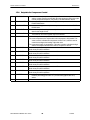
15.1. Voltage SI Control Method setpoints #1-18
#
1
2
NAME
STAGE DELAY
STAGE CUT OUT
3
4
5
6
7
8
9
10
11
12
13
14
15
16
17
18
STAGE 1 CUT IN
STAGE 2 CUT IN
STAGE 3 CUT IN
STAGE 4 CUT IN
STAGE 5 CUT IN
STAGE 6 CUT IN
STAGE 7 CUT IN
STAGE 8 CUT IN
STAGE 9 CUT IN
STAGE 10 CUT IN
STAGE 11 CUT IN
STAGE 12 CUT IN
STAGE 13 CUT IN
STAGE 14 CUT IN
STAGE 15 CUT IN
STAGE 16 CUT IN
DESCRIPTION
Delay between stages being turned on.
Off set used in calculating the cut out value. Subtracted from the stage cut in set
points #3 through #18
STAGE 1 cut in, set point value contains the value when this stage is turned on.
STAGE 2 cut in, set point value contains the value when this stage is turned on.
STAGE 3 cut in, set point value contains the value when this stage is turned on.
STAGE 4 cut in, set point value contains the value when this stage is turned on.
STAGE 5 cut in, set point value contains the value when this stage is turned on.
STAGE 6 cut in, set point value contains the value when this stage is turned on.
STAGE 7 cut in, set point value contains the value when this stage is turned on.
STAGE 8 cut in, set point value contains the value when this stage is turned on.
STAGE 9 cut in, set point value contains the value when this stage is turned on.
STAGE 10 cut in, set point value contains the value when this stage is turned on.
STAGE 11 cut in, set point value contains the value when this stage is turned on.
STAGE 12 cut in, set point value contains the value when this stage is turned on.
STAGE 13 cut in, set point value contains the value when this stage is turned on.
STAGE 14 cut in, set point value contains the value when this stage is turned on.
STAGE 15 cut in, set point value contains the value when this stage is turned on.
STAGE 16 cut in, set point value contains the value when this stage is turned on.
MCS-8 REFRIG V8 MANUAL REV 1.0.DOC
30
11/07/01
MICRO CONTROL SYSTEMS
REVISION 1.0
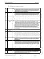
15.2. Setpoints for Unit Control Options
19
BARREL HEATER
20
21
22
Not Used
Not Used
LOW AMBIENT
23
POWERUP DELAY
24
HI AMBIENT
The barrel heater to turned on when the ambient temperature is less than this
value and turned off when the ambient temperature is greater than this value
plus 5.0°F (or 2.5°C)
Not Used
Not Used
If the ambient temperature is below this value the package will be disabled, unit
state will be AMBIENT OFF. Once off on low ambient the unit will remain off
until the ambient raises above this set point value by 5.0F (or 2.5C).
This is the time that the system will remain in the START UP state before
moving to the next state.
If the ambient temperature is above this value the package will be disabled, unit
state will be AMBIENT OFF. Once off on high ambient the unit will remain
off until the ambient drops below this set point value by 5.0F (or 2.5C).
MCS-8 REFRIG V8 MANUAL REV 1.0.DOC
31
11/07/01
MICRO CONTROL SYSTEMS
REVISION 1.0
15.3. Setpoints for Condenser Control
45
CND STG1 ON
46
CND STG1 OFF
47
48
49
CND DIFF ON
CND DIFF OFF
CND MIN RUN
50
CND VLV TARG
51
CND VLV DIV
52
53
CND VLV MIN
CND VLV ROC-
54
55
5659
CND MIN SPD
CND MAX SPD
Not Used
Air cooled- When the discharge pressure is above this value, turn on the first
stage of the condenser fans.
Air cooled- If stage 1 is on and the discharge pressure drops below this value turn
off the first stage of condenser fans.
Air cooled- Differential PSI to turn on the remaining stages of condenser fans.
Air cooled- Differential PSI to turn off the remaining stages of condenser fans.
Air cooled- Once a condenser fan stage has been turned on, it will remain on for
at least the amount of minutes specified in this set point.
Water cooled- Target discharge pressure to maintain by integration and Rate of
Change logic..
Water cooled- Usually 1. Allows control of the amount the valve is adjusted. The
larger the number the smaller the valve adjustment.
Water cooled- Minimum valve opening percentage allowed.
Water cooled- Maximum negative discharge pressure Rate of Change allowed. If
the actual rate of change is less then this set point then stop opening the
valve. The absolute value of this set point also severs as the maximum
positive rate of change allowed. If the actual rate of changes is greater than
the absolute value of this setpoint then stop closing the valve.
Minimum speed percentage for variable speed condenser control.
Maximum speed percentage for variable speed condenser control.
Not Used
MCS-8 REFRIG V8 MANUAL REV 1.0.DOC
32
11/07/01
MICRO CONTROL SYSTEMS
REVISION 1.0
15.4. Setpoints for Compressor Control
60
PMP DWN ON
61
PMP DWN OFF
62
PMP DWN DELY
63
ANTI-CYCLE
64
COMP MIN RUN
65
FLA COMP#1
66
FLA COMP#2
67
FLA COMP#3
68
FLA COMP#4
69
FLA COMP#5
70
FLA COMP#6
71
FLA COMP#7
72
FLA COMP#8
73
STARTER DLAY
74
Not Used
When the continuous pump down option is specified and the compressor is off
and the suction pressures exceed this value the compressor will go through a
normal pump down sequence. Only used in CHL R08 software version.
This is the suction pressure value for turning off the compressor when in the
PUMP DOWN state.
Maximum time delay (in seconds) that a compressor can remain in the PUMP
DOWN state.
This is the anti cycle time delay (in seconds). A circuit will remain in the ANTICYC
state for this length of time.
This is the minimum run time (in minutes) for a compressor once it is turned on.
This minimum run time is bypass only for the safeties.
Full Load Amps for the compressor on circuit 1.
For screw compressors, the ampere when the compressor is fully loaded. This
value is used to calculate the compressor current FLA %, which is used to
control the loading and unloading of the slide valve.
For screw and all types of compressors, This value is used to calculate the high
and the low ampere safeties limits. Refer to set points 75 and 76.
Full Load Amps for the compressor on circuit 2.
Refer in set point 65 for definition.
Full Load Amps for the compressor on circuit 3.
Refer in set point 65 for definition.
Full Load Amps for the compressor on circuit 4.
Refer in set point 65 for definition.
Full Load Amps for the compressor on circuit 5.
Refer in set point 65 for definition.
Full Load Amps for the compressor on circuit 6.
Refer in set point 65 for definition.
Full Load Amps for the compressor on circuit 7.
Refer in set point 65 for definition.
Full Load Amps for the compressor on circuit 8.
Refer in set point 65 for definition.
Time delay (in seconds) Between the first and second relay being turned on.
Used for part wind (typical value of 1) and star delta (typical value of 5)
starter.
Not Used
MCS-8 REFRIG V8 MANUAL REV 1.0.DOC
33
11/07/01
MICRO CONTROL SYSTEMS
REVISION 1.0
15.5. Setpoints for Compressor Safeties
75
HI AMPS
76
LO AMPS
77
LOW SUCTION
78
LO SUCT
UNLD
79
80
LOW SUCT
RELD
UNSAFE SUCT
81
HI DISCH PSI
82
HI DISC UNLD
83
84
85
HI DISC RELD
Not Used
LO DISC PSI
This set point is a percentage of the FLA; it is used to create the high amp draw limit.
Depending on the circuit that is being tested; the value of this set point is multiplied
by either the value in set points 65 through 72 to obtain the circuit’s high limit. This
value is tested in the high amp safety, if the amps exceed this value for the time
specified in this set point the safety is tripped.
This set point is a percentage of the FLA; it is used to create the low amp draw limit.
Depending on the circuit that is being tested; the value of this set point is multiplied
by either the value in set points 65 through 72 to obtain the circuit’s low limit. This
value is tested in the low amp draw safety, if the amps exceed this value for the
time specified in this set point the safety is tripped.
If active, the system checks for low suction pressure for each running compressor. The
system will compare the suction pressure sensor reading to this value. It must be
less than the value for the period of time specified in the set point before this set
point will trip.
The purpose of this set point is to take corrective action before a low suction pressure
safety occurs. If a circuit has more than one step and it is fully loaded and if the
suction pressure is less than the value of the safety set point (LOW SUCTION) plus
the value of this set point, the system will turn off one step of capacity. An infinite
step compressor will be forced to unload until the suction pressure raise above the
calculated value. The circuit state will be changed to LO SUCT HOLD. The circuit
will remain in this state for a minimum of 5 minutes. At that time, if the suction
pressure has increased to a level greater then the value of set point LOW
SUCTION plus the value of set point LOW SUCT RELD the compressor will return
to normal control.
See set point 78 description
If active, the system checks for low suction pressure that is in a unsafe condition for
each running compressor. The system will compare the suction pressure sensor
reading to this value. It must be less than the value for the period of time specified
in the set point before this set point will trip. Note the time period specified should be
very short, 2-5 seconds. This safety set point trips the circuit to the LOCKOUT state
immediately, no retry.
If active, the system checks for high discharge pressure condition for each running
compressor. The system will compare the discharge pressure sensor reading to
this value. It must be greater for the period of time specified in the set point before
this safety will trip.
The purpose of this set point is to take corrective action before a high discharge
pressure safety occurs. If a circuit has more than one step and it is fully loaded and
its discharge pressure exceeds the value of the safety set point HI DISCH PSI (set
point 81) minus this set point, the system will turn off one step of capacity. A screw
compressor will be forced to unload until the discharge pressure falls below the
calculated value. The circuit state will be changed to HI DISC HLD. The circuit will
remain in this state for a minimum of 5 minutes. At that time if the discharge
pressure has dropped below the value of the HI DISCH PSI minus the HI DISC
RELD (set point 83) the compressor will return to normal control.
This set point works in conjunction with set point 82. Refer to that set points description.
Not Used
If active, the system checks for low discharge pressure. The system will compare the
sensor reading to this value. It must be less than the value for the period of time
specified in the set point before a safety trip occurs.
MCS-8 REFRIG V8 MANUAL REV 1.0.DOC
34
11/07/01
MICRO CONTROL SYSTEMS
86
87
Not Used
HI DISCH TMP
88
HI DISC UNLD
89
90
91
HDISC T RELD
Not Used
LOW OIL DIF
92
UNSAFE OIL
93
94
Not Used
HI OIL TEMP
95
HI MTR TEMP
96
NO CMP
PROOF
DIRTY FILTER
97
9899
100
101102
103
104
REVISION 1.0
If active, the system checks for high discharge temperature condition for each circuit
that has at least one step on. The system will compare the discharge temperature
sensor reading to this value. It must be greater for the period of time specified in the
set point before this safety will trip.
The purpose of this set point is to take corrective action before a high discharge
temperature safety occurs. If a circuit has more than one step and it is fully loaded
and its discharge temperature exceeds the value of the safety set point HI DISCH
TMP (set point 87) minus this set point, the system will turn off one step of capacity.
A screw compressor will be force to unload until the discharge temperature falls
below the calculated value. The circuit state will be changed to HI DISC HLD. The
circuit will remain in this state for a minimum of 5 minutes. At that time if the
discharge temperature has dropped below the value of the HI DISCH TMP minus
the HI DISC RELD (set point 89) the compressor will return to normal control.
This set point works in conjunction with set point 88. Refer to that set points description.
If active, the system checks for low differential oil pressure. The system will compare the
calculated differential oil pressure to this value. It must be less than the value for the
period of time specified in the set point before the safety will trip.
If active, the system checks for low differential oil pressure. The system will compare the
calculated differential oil pressure to this value. It must be less than the value for the
period of time specified in the set point before the safety will trip. The time delay for
this set point should be very short 2-5 seconds. This safety trips to a lockout no
retries are attempted. Manual intervention is required.
Not Used
If active, the system checks for high oil temperature. The system will compare the oil
temperature sensor reading to this value. It must be ON or greater for the period of
time specified in the set point before this set point will trip. The sensor can be either
an analog or digital input.
If active, the system checks for high motor temperature. This can be either a digital input
or an analog input, the system will compare the sensor reading to this value. It must
be ON or greater for the period of time specified in the set point before this set point
will trip.
If this set point is active and there is a digital input indicated for compressor proof, when
the compressor is on, the compressor proof will be checked for that circuit.
Only used for screw compressors. If the discharge pressure minus the oil filter pressure
is less than this value for the time specified a safety trip will occur.
Not Used
PHASE LOSS
DEFROST
Used of individual compressor phase loss safeties.
SEE DEFROST SETPOINT POINTS FOR DESCRIPTION.
LEAD COMP
Enables the user to specify the lead compressor. If a value is less than the maximum
number of compressor the lead indicator is set to this value. If the value is zero then
auto rotation is enabled.
Specifies the number of days between rotation (setpoint #103 must be set to zero to
enable auto rotation). If the value is zero then rotation will occur with every capacity
cycle.
COMP
ROTATION
MCS-8 REFRIG V8 MANUAL REV 1.0.DOC
35
11/07/01
MICRO CONTROL SYSTEMS
REVISION 1.0
15.6. Setpoints for Unit Safeties
111
FREEZE
112
NO STOP
If active, the system checks for freeze protection. The system will compare the
chilled water out temperature to this value. It must be less than the value for
the period of time specified in the set point before this safety will trip.
This set point is used to insure that a compressor is actually off when the system
has called for it to be off. The value of the set point contains a percentage of
the FLA COMP set points 65-72. If the compressor ampere is greater then
this percentage of the FLA setpoint for the period specified the compressor is
still running and the entire unit is locked out and a NO STOP alarm is
generated. If a Control power relay is setup then it will be turned off when this
safety trips.
MCS-8 REFRIG V8 MANUAL REV 1.0.DOC
36
11/07/01
MICRO CONTROL SYSTEMS
REVISION 1.0
15.7. Setpoints for Defrost
90
DEF TMP LOCK
101
102
109
110
DEF-HI TEMP
DEF-MED TEMP
MAX DEF EVAP
DRIP DOWN
113
114
115
116
117
118
119
DEF-HI PSI
DEF-HI TIME
DEF-MED PSI
DEF-MED TIME
DEF-LO PSI
DEF-LO TIME
DEF-DEHUM
Time duration, in minutes, to lock in the current type of defrost to avoid falsely
changing the setpoints due to a raise in supply temperature caused by the
heat added during a defrost cycle.
The lower boundary for determining a HI TEMP defrost type.
The lower boundary for determining a MED TEMP defrost type
The maximum number of circuits allowed in defrost at the same time.
Time duration, in minutes, to hold the liquid line solenoid off after hot gas defrost
to allow time for the water to drip down off the coil.
The evaporator pressure setpoint for starting a HI TEMP defrost.
Time duration, in minutes, for a HI TEMP hot gas defrost
The evaporator pressure setpoint for starting a MED TEMP defrost.
Time duration, in minutes, for a MED TEMP hot gas defrost
The evaporator pressure setpoint for starting a LO TEMP defrost.
Time duration, in minutes, for a LO TEMP hot gas defrost
The evaporator pressure setpoint for starting a DEHUM defrost.
MCS-8 REFRIG V8 MANUAL REV 1.0.DOC
37
11/07/01
MICRO CONTROL SYSTEMS
REVISION 1.0
16. MCS-8 AUTHORIZATION FUNCTION
The authorization code is a special four-character code that enables access in to the MCS-8
system. The code must be numeric with values between 1 and 8 if it is to be entered from the
Keypad/Display. If the system is being accessed via PC-Connect program, the code may consist of
any valid alpha/numeric characters. Each system can have up to 15 different authorization codes.
This provides the capability of issuing different codes to different people if desired. There are four
levels of authorization, which provide different capabilities with in the system. The authorization
code and the associated level can not be displayed or viewed in an MCS-8 system. These are
established when building the configuration file in the PC-Config program. The authorization codes
must be protected and remain confidential, if they are compromised unauthorized personnel can
gain access to the system.
From the Keypad/Display the following changes can be made based upon the authorization level:
FUNCTION
SENSOR OFFSETS
SENSOR DIAGOSTICS
CLEAR ALARM HISTORY
CLEAR POINT INFORMATION
DATE & TIME SET
DAY OF WEEK SET
CHANGE NO FLOW LOCKOUT OR SHUT DOWN
CHANGE ROTATE YES OR NO
CHANGE MANUAL/AUTO SETTINGS
CHANGE SET POINT VALUES*
CHANGE OPERATING SCHEDULES
CHANGE HOLIDAY DATES
LOCK OUT RESET
VIEW
SERVICE
NO
NO
NO
NO
YES
YES
NO
NO
NO
NO
NO
NO
YES
YES
YES
NO
NO
YES
YES
NO
NO
NO
YES
YES
YES
YES
SUPERVISORY
YES
YES
NO
NO
YES
YES
NO
NO
YES
YES
YES
YES
YES
FACTORY
*Note - before a set point can be changed the set point must be able to be viewed.
MCS-8 REFRIG V8 MANUAL REV 1.0.DOC
38
11/07/01
YES
YES
YES
YES
YES
YES
YES
YES
YES
YES
YES
YES
YES
MICRO CONTROL SYSTEMS
REVISION 1.0
17. MCS-8 Standard Control Options
The following options are specified in the PC-Config program when building the configuration.
These options are used to personalize the system to meet the individual control requirements.
17.1. General Options
!
!
!
!
!
!
!
17.2.
Control method can be based upon the control zone strategy or upon a voltage input that
indicates the number of stages to be on.
The control temperature can specify either the return or leaving sensor.
Specify if the anti recycle timer should start when the compressor is turned on or turned off. (All
circuits)
Number of circuits, maximum of eight.
Alarm RO, generate an ALARM RO. This point will be turned on when ever an alarm is
generated.
Specify auto rotation for circuits.
Low and/or high ambient shut down.
Compressor Options
!
Type of compressors:
! Reciprocating with oil,
! Reciprocating with out oil,
! Screw with oil,
! Scroll,
!
Four compressor steps per circuit can be supported. Compressor plus three additional steps
of either compressors or unloaders and hot gas bypass points. Note, compressor safeties
relate to a circuit. If multiple compressors are on a circuit and a safety trips all compressor on
that circuit will be turned off.
!
Specify that part winding, two RO points will be used with fixed step compressors, the first RO
will be turned on with the second RO being turn on the number of seconds later that is
specified in set point #73. (By circuit) If not part winding, only allocate one RO point for the
compressor.
!
Type of pump down, when the compressor is off, continuous will cause the compressor to be
turned on if the suction pressure rises above the set point value. Else, the compressor will be
pumped down only when the compressor is being turned off. Note, when the compressor is
started the liquid line solenoid is not opened until the suction pressure reaches the value that is
contained in the pump down set point. A liquid line solenoid is required. (All circuits)
17.3. Condenser Options
!
!
Number of condensing stages.
Type of condenser:
! None,
! RO Step Common (all compressors monitored for discharge pressure),
! RO Step Individual per circuit (compressor on circuit monitored for discharge pressure),
! RO Step Combined, circuits 1 & 2 and circuits 3 & 4 will share a condenser (compressor
on related circuits monitored for discharge pressure),
! All of the RO Step type condenser can have a variable speed fan per circuit,
MCS-8 REFRIG V8 MANUAL REV 1.0.DOC
39
11/07/01
MICRO CONTROL SYSTEMS
!
REVISION 1.0
Modulating Common. This is usually used to control a water condenser with a value that
will be modulated depending on the rate of change of the discharge pressure
17.4. Unit Barrel Heater Options
!
Unit Barrel Heater, if specified a heater for the unit barrel will be controlled based upon ambient
temperature and set point #19, BARREL HEATER.
17.5. Hot Gas Bypass
HOT GAS BYPASS used as the 1st stage of capacity.
17.6. On/Off Switches
!
The following digital input switches can be associated with the system, their action will affect
the unit or an individual circuit, then action will only affect that circuit:
!
Flow switch, if off the system has lost flow. The system wills either lock out, if NO FLOW set
point is active, or shut down, if NO FLOW set point is inactive.
!
Pump down switch, if on and the compressor is off, will not start the compressor. If the
compressor is on, the system moves to the pump down state to begin the process of turning
off the compressor(s) in normal steps.
!
Run/Stop, if off the system will not run. This is usually wired to a RUN/STOP switch that is
manually positioned. If the system is running, the system moves all circuits (compressor) to off
in normal steps.
!
Network Run/Stop, if off the system will not run. This input is provided by another system that
resides on the network. It functions in the same matter as the Run/Stop switch.
!
Emergency Stop switch, if on, the system will be shut down immediately and will remain
disabled until the switch is off.
17.7. Low Suction Holding
This option is activated when the set point #78, LO SUCT UNLD, is active. The purpose of this
option is to take corrective action prior to a safety being tripped. When the suction pressure is
below the value calculated by adding the value of this set point to the value of the LOW SUCTION
set point for the time specified, the system will take the following action:
!
For a fixed step compressor, the system will turn off one step of capacity associated with that
compressor. The circuit (compressor) state will be LO SUCT HOLD. The circuit will remain in
that state until the capacity control indicates that another step is to be unloaded or if after 5
minutes the suction pressure has turned to normal.
Normal pressure is the value calculated by adding the value of the LO SUCT RELD set point 79 to
the value of the LOW SUCTION set point 77.
Refer to set point #78 and 79 for additional information.
MCS-8 REFRIG V8 MANUAL REV 1.0.DOC
40
11/07/01
MICRO CONTROL SYSTEMS
REVISION 1.0
17.8. High Discharge Pressure Holding
This option is activated when the set point #82, HI DISC UNLD, is active. The purpose of this option
is to take corrective action prior to a safety being tripped. When the discharge pressure is above
the value calculated by subtracting the value of this set point from the value of the HI DISCH PSI
set point for the time specified, the system will take the following action:
!
For a fixed step compressor, the system will turn off one step of capacity associated with that
compressor. The circuit (compressor) state will be HI DISC HOLD. The circuit will remain in
that state until the capacity control indicates that another step is to be unloaded or if after 5
minutes the discharge pressure has turned to normal.
Normal pressure is the value calculated by subtracting the value of the HI DISC RELD set point 83
to the value of the HI DISC PSI set point 81.
Refer to set point #82 and 83 for additional information.
17.9. High Discharge Temperature Holding
This option is activated when the set point #88, HI DISC UNLD, is active. The purpose of this option
is to take corrective action prior to a safety being tripped. When the discharge temperature is above
the value calculated by subtracting the value of this set point from the value of the HI DISCH TMP
set point for the time specified, the system will take the following action:
!
For a fixed step compressor, the system will turn off one step of capacity associated with that
compressor. The circuit (compressor) state will be HI DISC HOLD. The circuit will remain in
that state until the capacity control indicates that another step is to be unloaded or if after 5
minutes the discharge temperature has turned to normal.
Normal pressure is the value calculated by subtracting the value of the HI DISC RELD set point 89
to the value of the HI DISC TMP set point 87.
Refer to set point #88 and 89 for additional information.
17.10. High Ampere Holding
This option is activated when the set point #75, HI AMPS %, is active. The purpose of this option is
to take corrective action prior to a safety being tripped. When the amp draw is with in one-half of
the calculated HI AMP safety value, the system will take the following action:
For a fixed step compressor, the system will turn off one step of capacity associated with that
compressor. The circuit (compressor) state will be HI AMP HOLD. The circuit will remain in that
state until the capacity control indicates that another step is to be unloaded or if after 5 minutes the
amp draw has turned to normal.
17.11. Control Power Relay –No Stop
This option provides the capability of interrupting the power supply to the compressors in the
system. A relay output, referred to as the control relay, must be wired so that when it is off no power
reaches the compressors. This is a safety measure that will insure that the compressors are off
then the system calls for them to be off. The relay output must be indicated in the PC-Config
program and set point 112, NO STOP, must be active. The system will continually monitor the amp
draw of compressors that the system has in an off state. The system will calculate the minimum
amp draw by multiplying the FLA for that compressor times the percentage value in the NO STOP
set point. If the amp draw is greater than this value for the time specified; the system will turn the
MCS-8 REFRIG V8 MANUAL REV 1.0.DOC
41
11/07/01
MICRO CONTROL SYSTEMS
REVISION 1.0
control relay off, generate a NO STOP alarm and place the system in a lockout state. This provides
an additional level of protection.
17.12. Part Wind or Star Delta Starter
Either a part winding or star delta type of compressor starter is supported. This option is specified in
the PC-Config program and will require two successive relay output points. When this option is
specified, set point #73, STARTER DLAY, must contain the delay in seconds before the second
relay output is turned on. This delay is normally 1 second for part winding or 5 seconds for a star
delta starter. With this option, when a compressor is to be turned on, the first relay output is turned
on and the system will wait the time specified in set point 73 before the second relay output is
turned on.
17.13. Low & High Ambient Shutdown
The system supports both a low and a high ambient shut down. This option requires an ambient
temperature sensor and both LOW AMB OFF set point (#24) and HIGH AMB OFF set point (#26).
The AMBIENT OFF state is entered when the ambient temperature falls below the LOW AMB OFF
set point (#24) or is above the HIGH AMB OFF set point (#26). The system will remain in this state
until the ambient temperature raises 5.0F (or 2.5C) above the LOW AMB OFF set point value or
drops 5.0F (or 2.5C) below the HIGH AMB OFF set point value. When the unit is in this state, the
individual circuit states if active are moved to the CMP IS OFF state through the normal staging
function. One capacity STEP will be moved per second.
17.14. English or Metric sensor readings
The system supports either English or Metric sensor readings, this is specified in the PC-Config
program. All sensor values and all software-coded offsets are automatically converted into the
option selected and displayed with the appropriate character. The following table contains the
display character:
SENSOR READING
Temperature
Pressure – Gage Reading
Pressure – Absolute Reading
Humidity
Digital or Switch
Amp or CT
Voltage
Refrigeration Level
ENGLISH
CHARACTER
F
P
p
%
METRIC
CHARACTER
C
B
b
%
A
V
%
A
V
%
NOTE: Set point values are NOT automatically adjusted. They must be set up for the proper
method of sensor readings. Their display character will be automatically adjusted.
17.15. Compressor Auto Rotation
The auto rotation option is selected by setting the value in set point #103, LEAD COMP to zero. If
this value is not zero, it will contain the number of the lead circuit (compressor) and auto rotation is
disabled. Note this set point can be manually changed to force a different compressor as the lead
compressor or to enable auto rotation.
MCS-8 REFRIG V8 MANUAL REV 1.0.DOC
42
11/07/01
MICRO CONTROL SYSTEMS
REVISION 1.0
When this option is enabled, the system will rotate the compressors based upon the value in set
point # 104, CMP ROTATION.
If set point # 104 value is zero, rotation will occur with every complete capacity cycle and the
next compressor will be selected as the lead compressor.
Else, the value is the number of days between rotation. At midnight the system will check if it is
time to rotate compressors. If yes, the system will check the run hours on each compressor
and select the one with the least amount of run hours to be the lead compressor.
If set point # 104 is set up as an ALARM type of set point, a compressor rotation message will be
generated each time a compressor is rotated.
MCS-8 REFRIG V8 MANUAL REV 1.0.DOC
43
11/07/01
MICRO CONTROL SYSTEMS
REVISION 1.0
18. MCS-8 Alarms and Safeties
18.1. Introduction
There are three types of alarms that are generated by the MCS-8 control logic:
!
!
!
Information only alarms,
MCS-8 system alarms and
Unit set point safety alarms.
All of the alarms have the same format. The alarm is identified and it is date time stamped. Alarms
can be viewed from the MCS-8 by pressing the ALARM STATUS (4) key or from the PC-Connect
program.
18.2. Information only alarms
18.2.1. System generated alarms
The following alarms are generated to provided information; they will not cause a change in the
control algorithm such as a lock out condition or a relay output being forced off.
!
!
!
!
!
!
!
!
!
!
!
POWER FAILED
POWER RETURNED
COMPUTER RESET
BATTERY FAILED
LCD FAILURE
HW DATE INVALID
HW TIME INVALID
SW DATE INVALID
SW TIME INVALID
RAM INTEGRITY
WATCHDOG RESET
18.2.2. Alarms as a result of individual action
The following alarms indicate that an individual took action:
!
!
!
!
!
!
!
!
ALARMS CLEARED
STPT CHANGED
RO MANUAL
AO MANUAL
SI MANUAL
POINT INFO CLEAR
CLOCK SET
CFG DOWNLOADED
18.2.3. Alarms generated by the control algorithm
The following alarms indicate that the control algorithm took action:
!
!
ROTATED LEAD
DAYLIGHT SAVINGS
MCS-8 REFRIG V8 MANUAL REV 1.0.DOC
44
11/07/01
MICRO CONTROL SYSTEMS
REVISION 1.0
18.3. MCS-8 system alarms
18.3.1. Alarms are generated by the MCS-8 control algorithm:
18.3.1.1.Configuration problem alarms
These alarms indicate a problem with the configuration file that has been loaded into the system.
The system is not operational, a configuration must be transmitted to the unit form PC-Connect or
the Config chip must be replaced with a valid one.
!
!
!
INVALID CONFIG. (check sums are incorrect)
INVALID CFG VER (version number of the configuration is invalid)
INVALID CFG TYPE (the type does not agree with software, unit software with a
home unit configuration)
18.3.1.2.MCS local network problem alarms
These alarms indicate problems with the MCS local network, the system can be accessed but the
system is in a lock out state, LOST I/O.
!
!
!
MCS-RO#1 LOST (#1-5) – Communication problem with a relay output board.
MCS-SI#1 LOST (#1-5) – Communication problem with a sensor input board.
LOST IO SHUTDOWN – Unit locked out because of communication problem.
18.3.1.3.Key sensors problem alarms
This alarm indicate a problem with a key sensor, it is either shorted or open. The alarm will contain
ALARM followed by the 8-character name of the sensor.
The following sensors related to the entire system are tested:
!
ambient temperature, if failed: alarm only no lock out
The following circuit sensors are tested. If they fail that circuit only is locked out.
!
!
!
!
suction pressure and temperature
discharge pressure and temperature
oil pressure and temperature
motor temperature (if it is an analog input device)
18.3.1.4.EMERGENCY STOP alarm
This alarm indicates that the emergency stop switch has been turned on. The system can be
accessed but the entire system is in a lock out state.
!
EMERGENCY STOP
MCS-8 REFRIG V8 MANUAL REV 1.0.DOC
45
11/07/01
MICRO CONTROL SYSTEMS
REVISION 1.0
18.4. Set point safety alarms.
18.4.1. Introduction
The MCS-8 unit algorithm incorporates a number of safety checks to ensure that the various
components that make up the unit are not damaged. These types of safeties are based upon set
points. When a safety trips for the first time, the compressor will be set to “SAFETY TRIPPED”
state. The compressor will remain in “SAFETY TRIPPED” state for ten minutes and then move to
the “CMP IS OFF” state where the compressor will be allowed to run if required. If the same safety
trips occurs again within two hours of the first trip, the compressor will be set to “CMP LOCKED
OUT” state, which requires a manual reset to restart the compressor. In this matter the MCS-8
attempts to take corrective action to protect the compressors but avoid nuisance trips.
The time in the safety state and the time between safeties are specified in the individual set points.
This enables the times to be unique for each lock out set point.
18.4.2. Sensor inputs used in conjunction with MCS-8 set point safeties:
Suction Pressure
Pressure transducer to read the suction pressure. (Optional digital input)
Discharge Pressure
Pressure transducer to read the discharge pressure. (Optional digital input)
Oil Pressure
Pressure to read the oil pressure (optional digital input)
Oil Differential Pressure
Calculated valve of the oil pressure as follows:
- Fixed step compressors, oil psi minus suction psi
- Screws with oil pump, Oil psi minus discharge psi
- Screws without oil pump, discharge psi minus suction psi
Oil Temperature
Either a temperature sensor or a digital input that indicates when a high temperature condition
exists.
Discharge Temperature
Either a temperature sensor or a digital input that indicates when a high temperature condition
exists.
Motor Temperature
Either a temperature sensor or a digital input that indicates when a high temperature condition
exists.
Motor Amps
Sensor input that measures AMP draw of the compressor. (optional digital input)
MCS-8 REFRIG V8 MANUAL REV 1.0.DOC
46
11/07/01
MICRO CONTROL SYSTEMS
REVISION 1.0
Motor Fault
A digital input that indicates when a motor fault condition exists or an analog sensor that will read
resistance value. If an analog sensor, a setpoint is required that contains the resistance value that
the sensor will indicate on safety trip. This is a general fault indicator, that may have been caused
by high temperature, amp draw etc.
Compress Proof
A digital input that when on indicates that a compressor is running.
Flow Switch
A digital input that indicates that flow through the unit barrel exists. There can be one switch per
unit or one for each circuit.
18.4.3. Set point safeties
For a safety to be interrogated, both the associated sensor input and the lockout set point must be
active. If a safety trips, the alarm name will consist of the set point name plus additional
identification such as point number or circuit number if applicable.
The system exercises “smart” safety testing in the following manner:
If a safety applies to a circuit and it is an active lockout type of a set point, the first time this safety
trips an alarm will be generated and the circuit will be shut down and placed in a safety state. After
ten minutes the system will reactivate this circuit if the safety condition is no longer true. If the same
safety trips within two hours, the circuit will be locked off and a manual intervention is required.
The time in the safety state and the time between safeties are specified in the individual set points.
This enables the times to be unique for each lock out set point.
The following are a list of safeties that are incorporated in the standard unit algorithm control for
fixed step compressors. These safeties are checked every second. Note, for a multiple circuit
system, each circuit is tested individually. If a safety condition exists, action will be taken with that
circuit only, other circuits will continue to function.
Freeze Protection
If the leaving liquid temperature drops below the set point value the system, and all circuits, will
enter a lockout state and a freeze notification alarm will be generated. You have the option of one
freeze protect for the package or individual freeze protections by circuit. This is selected at PCConfig time.
Phase Loss Protection
Phase loss, as indicated by the phase loss monitor, will result in the system and all circuits being
locked off and a phase loss notification alarm will be generated. No set point is required.
Emergency Stop
Emergency stop, as indicated by the emergency stop switch, will result in the system and all circuits
being locked off and an emergency stop notification alarm will be generated. No set point is
required.
Low Differential Oil Pressure
This safety is designed to meet the compressor manufacturer requirements on oil pressure. For the
first 5 (60 seconds if setup as Hitachi screw compressors) seconds following a compressor start
MCS-8 REFRIG V8 MANUAL REV 1.0.DOC
47
11/07/01
MICRO CONTROL SYSTEMS
REVISION 1.0
this safety is NOT checked. For the next 30 seconds, if the oil differential pressure drops below ½
of the value of the set point or the digital input turns ON and it remains there for the time specified in
the safety time of that set point, the compressor will be locked out and a low oil alarm generated.
After this time period, if the oil differential pressure drops below the value of the set point and it
remains there for the time specified in the safety time, the compressor will be locked out (as
described in section ‘Unit set point safety alarms.’) and a low oil alarm generated. This enables the
set point value and the safety time to be much tighter. This safety is interrogated when the
compressor is on and not in a pump down state.
Low Suction Pressure
If the suction pressure drops below the value of the set point or the digital input turns ON and it
remains there for the time specified in the safety time, the compressor will be locked out and a low
suction alarm generated. For the first 5 minutes after the compressor has started the safety time is
extend by 2 minutes, this enables the set point safety time to be set much tighter for normal
operation. This safety is bypassed when the compressor is in the “CMP PUMP DOWN” state. This
safety can also be used as a freeze protection based upon the suction PSI.
Unsafe Suction Pressure
This safety is similar to the low suction pressure safety except this set point can be set up with a
lower value and a very short safety time. If the suction pressure drops below the value of the set
point or the digital input turns ON and it remains there for the time specified in the safety time of that
set point, the compressor will be locked out and a low suction alarm generated. This safety will
always cause a lock out on the first trip requiring a manual reset to restart the compressor. For the
first 5 minutes after the compressor has started the safety time is extend by twice the normal time
delay, this enables the set point safety time to be set much tighter for normal operation. . This
safety is bypassed when the compressor is in the “CMP PUMP DOWN” state.
Low Discharge Pressure
If the discharge pressure drops below the value of the set point and it remains there for the time
specified in the safety time of that set point, the compressor will be locked out and a low discharge
alarm generated.
High Discharge Pressure
If the discharge pressure raised above the value of the set point or the digital input turns ON and it
remains there for the time specified in the safety time of that set point, the compressor will be
locked out and a high discharge alarm generated.
High Discharge Temperature
If the discharge temperature analog input raises above the value of the set point or the digital input
turns ON and it remains there for the time specified in the safety time, the compressor will be
locked out and a high temperature alarm generated.
HI Motor Temp or Motor Fault
If the high motor temperature input raises above the value of the set point or the digital input turns
ON and it remains there for the time specified in the safety time, the compressor will be locked out
and a high motor temperature or motor fault alarm generated.
MCS-8 REFRIG V8 MANUAL REV 1.0.DOC
48
11/07/01
MICRO CONTROL SYSTEMS
REVISION 1.0
Hi Oil Temp
If the oil temperature raises above the value of the set point or the digital input turns ON and it
remains there for the time specified in the safety time of that set point, the compressor will be
locked out and a high oil temperature alarm generated.
Hi Motor Amp
If the ampere analog input raises above the value of the set point or the digital input turns ON and it
remains there for the time specified in the safety time of that set point, the compressor will be
locked out and a high motor amp alarm generated. This safety is bypassed for the first 3 seconds
after a compressor has started.
Low Motor Amp
If the ampere analog input drops below the value of the set point and it remains there for the time
specified in the safety time of that set point, the compressor will be locked out and a low motor amp
alarm generated. This alarm can be used to indicate low refrigerant. This safety is bypassed for the
first 3 seconds after a compressor has started.
No Compress Proof
If a compressor is called to be on and the compressor proof input is off (this is a digital input), a NO
COMP PROOF alarm will be generated.
Dirty Oil Filter (Fixed Step Compressors only)
If the difference between the discharge pressure minus the oil pressure is above the value of the
set point and it remains there for the time specified in the safety time of that set point a dirty oil filter
alarm generated. If the difference raise 20.0 above the set point then the compressor is locked out
on the first trip requiring a manual reset to restart the compressor.
MCS-8 REFRIG V8 MANUAL REV 1.0.DOC
49
11/07/01
MICRO CONTROL SYSTEMS
REVISION 1.0
19. MCS-8 OEM Factory Checkout Procedure
19.1. Visual Check
!
!
!
!
!
!
!
!
120 VAC power wiring
Jumper settings
! sensor input
! address
! MCS communication termination
! EEPROM write protection
Sensor Wiring
MCS-IO Communication Wiring
LCD Connector (dot to mark on the board)
Keypad Connector (dot to mark on the board)
Chips
! Master software and chip
! I/O software
RO Wiring
Ensure that the EMG stop is on (closed position) or run/stop input off so that the unit will not run after power
applied to micro.
19.2.
!
!
!
!
!
!
!
MCS Power On (Compressor Power off)
MCS System on
LCD on and valid display - “MCS Initialization” then default screen
Communications light blinking if I/O units
Get AUTHORIZED
Check board version number: SERVICE DIAGNOSTICS/UNIT INFORMATION/HARDWARE
VERSION/ENTER (if change is required)
Check sensor readings
Manually bump (on then off) each point (take care your in control)
MCS-8 REFRIG V8 MANUAL REV 1.0.DOC
50
11/07/01
MICRO CONTROL SYSTEMS
REVISION 1.0
20. MCS-8 Compressor relay output sequence (examples)
-
20.1.
COMP 1A
COMP 1B
LLS 1
LLS 2
UNLD1-1
UNLD1-2
HGB1
DRIAN1
HGAS1
HGAS2
Reciprocating Compressor
st
Compressor 1 1 contractor
nd
(optional) Compressor 1 2 contractor (split winding makes 1 sec. after A)
Liquid line solenoid Evaporator #1
Liquid line solenoid Evaporator #2
(optional) unloader 1
(optional) unloader 2
(optional) Hot gas bypass capacity control solenoid
Hot gas coil drain solenoid
Hot gas defrost for evaporator #1
Hot gas defrost for evaporator #2
MCS-8 REFRIG V8 MANUAL REV 1.0.DOC
51
11/07/01
MICRO CONTROL SYSTEMS
REVISION 1.0
21. MCS-8 Keypad/Display Quick Reference- STATUS KEYS
• No authorization is required in the DISPLAY STATUS section for
viewing information.
• Pressing a key selects the 1st two lines of data. Repressing the
same key selects the next two lines, etc.
• The ALARM STATUS displays all alarms and lockouts while
LOCKOUT STATUS displays only active lockouts.
• The “+” and “-“ keys may be used with alarm & lockout status to
allow scrolling.
• If one or more Micro Control Expansion units are connected to a
Micro Control Center the data will be presented in a continuous
COMP1
LLS 1
ON
ON
ULS1-1
COMP2
OFF
ON
sequence. ADDITIONAL STATUS information shows names, total,
run hours and starts for all RO’s.
• SYSTEM PRESSURE displays information by circuit, SP suction
pressure, DP discharge pressure, OPD oil pump differential, AMP
or motor fault.
• LOCKOUT STATUS for lockouts caused by either suction
discharge oil or amps, the actual value at the time of the lockout of
the associated sensor is displayed.
Following info will
be repeated for all
active circuits)
LVG. LIQ
44.8F
RET. LIQ. 53.7F
FAN 1&2
FAN 3&4
ON
ON
LLS2
ULS2-1
ON
OFF
1 SP DP OPD AMP
69 185 116 43
AMB.TMP. 115.4F
EMG STOP
OFF
FAN 5&6
FAN 7&8
ON
ON
COMP3
LLS3
ON
ON
1 SUCT SAT SHEAT
51F 40F +11.4F
PMP DWW1
PMP DWW2
OFF
OFF
FAN 9&10
FAN 11&12
ON
ON
ULS3-1
OFF
1 DISC SAT SHEAT
158F 96F +61.8F
PMP DWW3
FLOW SW
OFF
ON
DISPLAY STATUS
LVG.LIQ. 44.8F
RET.LIQ. 53.7F
PUMP
FLOW SW
ON
ON
COMPRESSOR
STATUS
1
SYSTEM
PRESSURE
5
CONDENSOR
STATUS
2
SYSTEM
TEMPERATURE
6
EVAPORATOR
STATUS
3
ADDITIONTAL
STATUS INFO.
7
ALARM
STATUS
4
LOCKOUT
STATUS
8
COMP1 = 1015h
STARTS=0000210
LLS1 = 1015h
STARTS =000210
ULS1-1 = 0080h
STARTS = 00210
Chiller Configuration Example
1 APR 26 0:28:37
LOW SUCTION
2 APR 12 8:15:01
POWER RETURN
3 APR 12 8:11:11
POWER FAILED
MCS-8 REFRIG V8 MANUAL REV 1.0.DOC
•
•
•
•
•
•
•
•
•
Three reciprocating compressors
One unloader solenoid per compressor
One liquid line solenoid per compressor
Twelve condenser fans
Suction & discharge pressure per
compressor
Oil pressure per compressor
Leaving liquid temperature sensor
Return liquid temperature sensor
Ambient temperature sensor
52
8 APR 22
8:15:00
LOST IO SHUTDOWN
END OF LOCKOUTS
ENTR VIEW OPTION
11/07/01
MICRO CONTROL SYSTEMS
REVISION 1.0
22. MCS-8 Keypad/Display Quick Reference-ENTRY KEYS
• Different items will appear depending on the
package configuration and options selected.
• Units may be English or Metric.
• The clock is factory set at EST or EDST based
on time of year.
• The ENTRY keys (SERVICE,
SETPOINT,MANUAL and PROGRAM) provide
menu items, some of which when selected will
present sub menus.
• When making value changes the INCREASE
(+) & DECREASE (-) keys may be held for
continuous updating.
• Enter authorization code at the authorization
function within the SERVICE DIAGNOSTIC key
menu.
#1 LVG. LIQ. TARG
ENTR CHG +45.0F
#4 CTRL ZONE
ENTR CHG +2.0F
CONTROL STATUS
ENTR CHG OPTION
#5 CNTRL ZONE
ENTR CHG +1.0F
AUTHORIZATION
ENTR CHG OPTION
#7 PMP DN CTOUT
ENTR CHG +40.0P
SENSOR OFFSETS
ENTR CHG OPTION
#8 PMP DN DELAY
ENTR CHG 60S
SENSOR DIAGOSTIC
ENTR CHG OPTION
#9 CYCLE DELAY
ENTR CHG 300C
CLEAR ALRM HSTRY
ENTR CHG OPTION
#10 STEP SENSITY
ENTR CHG 5
CLEAR PT INFO
ENTR CHG OPTION
#11 STEP DELAY
ENTR CHG 300C
UNIT INFORMATION
ENTR CHG OPTION
DATE DISPLAY
ENTR CHG OPTION
TIME DISPLAY
ENTR CHG OPTION
DATE & TIME SET
ENTR CHG OPTION
DAY OF WEEK SET
ENTR CHG OPTION
OPERATING SCHEDS
ENTR CHG OPTION
ENTRY
RELAY OUTS MANAL
ENTR CHG OPTION
SERVICE
DIAGNOSTI
PROGRAM
OPTIONS
SETPOINTS
(SAFETIES)
INCREASE
(+)
MANUAL
(AUTO)
DECREASE
(-)
LOCKOUT
RESET
ENTER
ANALG OUTS MANAL
ENTR CHG OPTION
SENSOR INS MANAL
ENTR CHG OPTION
RESET LOCKTS?
ENTER KEY=YES
ENTER KEY
Selects options or enters
changes after adjustments
have been made.
53
INCREASE (+)
KEY &
DECREASE (-)
KEY
Used To adjust
values or change
options selected.
(SERVICE,
SETPOINTS,
MANUAL, &
PROGRAM keys.)
MICRO CONTROL SYSTEMS
23.
REVISION 1.0
MCS-8 & I/O Quick Reference Sheet
Wiring Guide Notes
• Relay Outputs (RO) 120 VAC 10 amps.
• SI 1-4 factory set for 4 wire differential inputs. (0 to 100 mvolts dc)
• SI 5-8 factory set for MCS-T100 temperature inputs. (0 to 5 volts dc)
• All analog inputs must have shield tied to GND.
• MCS-8 factory set address to MCS-8.
• MCS-I/O factory set address to MCSIO address 1.
• Detail of MCS-8 and I/O items next page.
High Voltage Wireway Relay Ouptus & 120 VAC 50/60 hertz Input
Preferred direction of wire
RO # 1
RO # 2
10 A Fuse #1
10 A Fuse #2
RO # 3
RO # 4
10 A Fuse #3
RO # 5
10 A Fuse #4
10 A Fuse #5
MCS-8
Rev. 1.5
© 1998
Micro Control
Systems, Inc.
Fort Myers,
Florida
LCD
Connector
"
MCSIO#1
"
MCSIO#2
"
MCSIO#3
"
10A Fuse #7
RO # 8
120 VAC
10A Fuse #8
315 ma Fuse
U14
XFMER
8/16
AC
U11
Software
EPROM
8/16
vdc
term
System uses either
XFMER or DC input
Configurator
EEROM
MCS-8
Keypad
Connector
RO # 7
10 A Fuse #6
Static RAM
Board
Select
LCD Contrast
Adjustment
RO # 6
An MCS-8 printed
circuit board may
also be used as an
MCS-I/O
U10
U13
GAL
RS232
Reset
Switch
Communications
Terminals, LED’s &
RS485 termination’s
SI 1 thru 8 Jumpers factory set for Analog
Digital
Analog
SI #1
Digital
Analog
SI #2
Digital
Analog
SI #3
Digital
Analog
SI #4
Digital
Analog
SI #5
Digital
Analog
SI #6
Digital
Analog
SI #7
:
Digital
Analog
SI #8
Analog
Output
+12
VDC
Low Voltage Wireway Sensor Input, Analog Output & Communications
Terminals Shielded cable only, preferred direction of wire
54
MCS
IO
:
RS
485
MICRO CONTROL SYSTEMS
REVISION 1.0
24. MCS-8 & I/O – Terminal Block Details
8 Relay Outptus (RO)
Common
Normally
Open
RO # 1
10 A Fuse #1
RO # 2
Line
Normally
Closed
RO # 3
10 A Fuse #2
RO # 4
10 A Fuse #3
10 A Fuse #4
RO # 8
10A Fuse #7
Ground
16 VDC
120 VAC
10A Fuse #8
315 ma Fuse
U14
Static RAM
Software
EPROM
U11
Configurator
EEROM
U10
XFMER
8/16
AC
8/16
vdc
term
System uses either
XFMER or DC input
"
MCSIO#2
"
MCSIO#3
"
MCSIO#1
Keypad
Connector
RO # 7
10 A Fuse #6
8 VDC
Ground
RO # 6
10 A Fuse #5
Board
Select
LCD Contrast
Adjustment
Neutral
RO # 5
MCS-8
Rev. 1.5
© 1998
Micro Control
Systems, Inc.
Fort Myers,
Florida
LCD
Connector
Optional UPS
120 VAC 50/60 hertz Input
To setup sensor
input jumpers see
form F603 for more
details
Reset
Switch
RS232
Communications
Terminals see form F604
for more details
SI 1 thru 8 Jumpers factory set for Analog
Digital
Analog
SI #1
Digital
Analog
Digital
Analog
SI #2
Digital
Digital
Analog
SI #3
Analog
SI #4
SI #5
Digital
Analog
Digital
Analog
SI #6
:
Digital
Analog
SI #7
SI #8
Analog
Output
+12
VDC
MCS
IO
Sensor Inputs 5 thru 8
+5VDC
Ground
:
RS
485
RS485 Communications
+
Signal
0 to 10
VDC
Ground
+
12 VDC Output max 500ma
+12 VDC
55
Ground
MCS IO Communications
Analog Output
4 to 20
-
Not Used
Ground
-
Ground
MICRO CONTROL SYSTEMS
REVISION 1.0
MCS-8 Sensors Quick Reference Sheet– Temp./Humd. Sensors
25.
MCS-T100 (SI #1 through 8, REV 1.5 & higher)
1.
2.
MCS-ZONE (SI #1 through 8, REV 1.5 & higher)
Connects to 1 of MCS Sensor Inputs 1through 8
Shielded cable GND drain must be connected to SI ‘GND’
Temp MCS-8 SI (inputs 1-8) jumper setting is ‘ANALOG’
3.
1.
2.
3.
MCS Sensor Input Terminal Strips
SENSOR (x)
MCS Sensor Input Terminal Strips
+5
GND
Connects to 1 of MCS Sensor Inputs 1 through 8
Shielded cable GND drain must be connected to SI ‘GND’
Temp MCS-8 SI (inputs 1-8) jumper setting is ‘ANALOG’
S1
BLK
+5
GND
S1
WH
+5
VDC
Shielded cable only - min.
24 awg stranded
Out
Temp
GND
Shielded cable - 18’ 24 awg supplied
MCS
H100
REV 2.0
LAYOUT B
MCS-ZONE
MCS-T100
MCS-SAIR (SI #1 through 8, REV 1.5 & higher)
1.
2.
3.
MCS-HUMD (SI #1 through 8, REV 1.5 & higher)
Connects to 1 of MCS Sensor Inputs 1through 8
Shielded cable GND drain must be connected to SI ‘GND’
Temperature MCS-8 SI (input 1-8) jumpers setting to
Analog’
Minimum extension inside duct 2.25”
Normal extension, as shown, 4.00”.
4.
5.
1.
2.
3.
4.
5.
MCS Sensor Input Terminal Strips
+5
BLK
GND
S1
Connects to 2 of MCS Sensor Inputs 1 through 8
Humidity MCS-8 SI (input 1-8) jumper setting is ANALOG’
+5 vdc & GND are common (only one connection required)
Temp. MCS-8 SI (input 1-8) jumper setting is ‘ANALOG’
Shielded cable GND drain must be connected to SI ‘GND’
MCS Sensor Input Terminal Strips
+12 OUT SENSOR (x1) SENSOR(x2)
+12
Shielded cable - 18’ 24 awg supplied
GND
+5
GND
S1
+5
WH
+5
VDC
GND
+12
VDC
Min = 2.125”
Max = 4.500”
GND
circuits
Humd
Out
MCS-SAIR
MCS-H100
56
Out
Temp
GND
S1
MICRO CONTROL SYSTEMS
REVISION 1.0
26. MCS-8 Sensors Quick Reference Sheet - Pressure Sensor & Digital
inputs
MCS-TI-500-xx (SI #1 thru 8, REV 1.5 & higher)
1.
2.
3.
4.
MCS-TI-500-xx pressure transducer (3 wire 0-5 vdc)
Wiring for 3 wire to SI# 1 through 8
Jumper settings for SI# 1 through 8 is ‘ANALOG’
Pressure range 0 - 500 psi
MCS Sensor Input Terminal Strips
SENSOR (x)
+5
GND
S1
RED
Dry Contact’s (SI#1 through 8, REV 1.5 & higher)
1.
2.
3.
4.
MCS Sensor Input Terminal Strips
Sensor (x)
WH or CLEAR
BLK
Digital inputs for use on sensor inputs (SI 1-8)
Dry Contact MCS-8 SI (input 1-8) jumper setting is
‘DIGITAL’
Verify with sensor diagnostic under service on
keypad
Shielded cable GND drain must be connected to SI
“GND”
+5
MCS DRY CONTACT DI (SI 1-8)
MCS-TI-x00-yy
MCS-CT-xxx (SI #1 through 8, REV 1.5 & higher)
Connects to 1 of MCS sensor inputs 1 through 8
The current transformer may be 100:5 or 250:5
The size of the CT (xxx) must be larger than FLA
AMPS jumper setting is ‘ANALOG’
For wiring only remove terminal block. DO NOT
REMOVE PRINTED CIRCUIT BOARD.
MCS Sensor Input Terminal Strip Sensor (x)
+5
GND
S1
Shielded cable - min. 24 awg stranded
GND
S1
Shielded cable - min. 24 awg stranded
Shielded cable - (20’ or
40’ 22 awg supplied)
1.
2.
3.
4.
5.
GND
S1
MCS-CT-xxx
57
MICRO CONTROL SYSTEMS
REVISION 1.0
27. MCS-8 Trouble Shooting Quick Reference Sheet
PROBLEM
A sensor input reads -99.9
A sensor input reads +999.9
A sensor is reading more than 3%
off
‘MCS CONTROLLER
INITIALIZATION’ on LCD display.
Top row of LCD display all bars &
2nd row blank.
LCD blank.
Lost I/O
Invalid reading on one sensor
input.
Changes to MCS not being made.
Invalid authorization
POTENTIAL SOLUTION
This indicates an open sensor input signal or 5 VDC problem.
•
Check sensor wiring for missing wire or poor connection.
•
Check sensor for bad sensor.
If less than 5 VDC is on the sensor 5 VDC terminal block, the problem is
with probably a shorted sensor. (A poly-fuse protests the board)
•
Remove all sensor input terminals.
•
Wait about 1 min. or until 5 VDC restored at sensor input.
•
Connect terminals 1 at time until short reappears.
This indicates a shorted sensor input signal.
•
Check sensor wiring for +5VDC shorted to signal etc.
•
Check sensor for bad sensor.
This indicates the sensor needs to be calibrated. (You need to have a
valid Auth code to change sensor offsets)
• Press Service Diagnostics, press until LCD display s sensor offset
option
st
• Press enter, 1 SI number & offset appears (i.e. Suct 1 = 0.0)
• Scroll using “increase(+)/decrease(-)” keys to find sensor to be
calibrated
• Press enter, use the “increase(+)/decrease(-)” keys to change the
calibration value. When value is correct, press enter.
Indicates Micro in constant reset.
•
Check incoming power > 105 VAC or 22 VAC
Indicates software chip problem possible.
•
Possible U11 software version incorrect or chip bad.
•
Possible U13 GAL chip incorrect or chip bad.
•
Possible bad connection or cable between LCD and MCS8
Indicates bad connection.
•
Connector J2 on MCS not on or offset on connector.
•
Resistor adjustment VR1 out of adjustment.
Indicates communications problem.
•
Verify RS485 LED blinking.
•
Verify termination jumper J6 only on at MCS-8 & last I/O.
•
Verify MCS-8 & I/O address’s set correctly.
•
Verify wiring from MCS-8 to each I/O correct.
•
Check fuses/120 VAC on I/O units
This indicates an input problem with 1 sensor.
•
Verify jumper settings correct for that SI.
This indicates inability to write to chip U10.
•
Verify ‘EEP WRITE ENABLE’ jumper W6 is on.
•
Not authorized
This indicates an invalid auth number.
Follow steps below for proper authorization
• Press SERVICE DIAGNOSTICS key until the authorization option
appears
• Press the ENTER key
• From the “Display Status” press keys corresponding to your
authorization number.
• Press ENTER
58
MICRO CONTROL SYSTEMS
PROBLEM
SI from AMPS board 10 A low.
INVALID CONFIG VER
INVALID CONFIG TYPE
INVALID CONFIG
Sensor input believed invalid
(Under Sensor Diagnostic Sub
Menu)
REVISION 1.0
POTENTIAL SOLUTION
This indicates a problem with this SI only.
•
Jumper setting on this SI in wrong position.
•
Incorrect sensor type used.
Indicates layout of CFG wrong.
•
CFG layout for different version than software chip U11.
Indicates U10 CFG incompatible with U11 software.
•
Example U10 CFG for home while U11 for unit.
Indicates Checksum invalid
•
Reload CFG
•
Verify Berg jumpers using Quick Reference Sheets
•
Check board version number
•
Check wiring of sensor
59