1
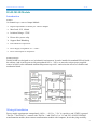
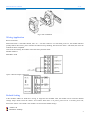
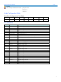
DAM-3014D
User’s Manual
Beijing ART Technology Development Co., Ltd.
DAM-3014D User’s Manual
V6.14
DAM-3014D Module
Introduction
Features
16-channel Open- collector Output Module
¾
Digital Output Mode:16-channel pen- collector output
¾
Max Load: 30V, 100mA
¾
Isolation Voltage: 3750V
¾ Direct drive power relay
¾ Support Dual Watchdog
¾
LED indicate the output state
¾
Power Supply: unregulated +10~+30VDC
¾
Power Consumption: 0.7W@24VDC
Industrial Design
DAM-3014D was designed to use in industrial environment. It can be installed in standard DIN rail inside
the cabinet. And it can be powered by unregulated 10VDC ~30VDC to meet the various power supplied
source in field. It also withstands ambient temperature up to 60℃ and resists the effects of vibration and
mechanical shock.
Wiring & Installation
Power supply requirements: unregulated +10VDC ~ +30 VDC. "+Vs" is a positive, and "GND" is ground.
"DATA +" and "DATA-" connect with "DATA +" and "DATA-"(or "A" and "B") of RS-232/RS-485
transformation module, then connect transformation module with computer, do not hot plug carefully.
2
DAM-3014D User’s Manual
V6.14
The power indicator flashes after wiring is correct, then you can communication with the host computer.
According to the label directs color to wiring:
+Vs (R) Red
GND(B) Black
DATA+ (Y) Yellow
DATA- (G) Green
DAM-3014D
Fig. 1 DAM-3014D Drawing
DAM-3014D can be installed in standard DIN rail inside the cabinet, it also can be installed by stacking
mode.
Fig.2 standard DIN installation
3
DAM-3014D User’s Manual
V6.14
Fig.3 stack installation
Wiring Application
Reset Connection:
Shorted the INIT * and GND shorted, add +10 ~ +30 VDC between +Vs and GND, power on, the module indicator
quickly flashes three times, power off until the indicator stops flashing, disconnect the INIT * and GND, then reset the
module has been completed.
After reset successfully, the module restore the factory default values:
Module Address: 1
Baud Rate: 9600
Open- collector Output Connection
Default Setting
If the module’s address or baud rate is wrong, or forget the last modified value, the module can be reverted to default
settings. Steps: Short-circuit the “INIT*” and “GND” when there is no power; power-on for 3 seconds, power off,
disconnect “INIT*” and “GND”. The module is reverted to the default settings.
Address: 00
Baud Rate :9600bps
4
DAM-3014D User’s Manual
V6.14
Noparity
The serial port default work mode:
parity bit: none
data bits: 8
stop bit: 1
Code Configuration Table
Baud Rate Configuration Code Table
Code
00
01
02
03
Rate
1200
2400
4800
9600
04
19200
05
38400
06
57600
07
115200
Pin Definition
Pin
Name
Function
1
OUT13
Digital output 13-ch
2
OUT14
Digital output 14-ch
3
OUT15
Digital output 15-ch
4
EXTPWR
External power (+)
5
OUTCOM
External power (-)
6~8
NC
9
INIT*
reset pin, connect with(B)GND, then power-on to reset
10
(Y)DATA+
RS-485 positive
11
(G)DATA-
RS-485 negative
12
(R)+Vs
DC Power Supply (+),+10~+30V DC
13
(B)GND
DC Power Supply (-)
14
OUT0
Digital output 0-ch
15
OUT1
Digital output 1-ch
16
OUT2
Digital output 2-ch
17
OUT3
Digital output 3-ch
18
OUT4
Digital output 4-ch
19
OUT5
Digital output 5-ch
20
OUT6
Digital output t 6-ch
21
OUT7
Digital output 7-ch
22
OUT8
Digital output 8-ch
23
OUT9
Digital output 9-ch
24
OUT10
Digital output 10-ch
25
OUT11
Digital output 11-ch
26
OUT12
Digital output 12-ch
5


![New tool workshop: First step: After reading [TEXT] and based on](http://vs1.manualzilla.com/store/data/005783105_1-e6c0fd715dacf809f77868c696f00d08-150x150.png)