1
F K - R I 012-1 (i-004
RL01/RL02 DISK
SUBSYSTEM
USER'S GUIDE
»
digital equipment corporation • Colorado springs, Colorado
1st I ilition. Dccemhci lirs
2nd Pimting ( R e x ) . September I9"7*)
3rd P r i n t i n g ( R e x I. June l l )S()
4th Pi intuit: I R e x ). October I ' J S O
C opxnght
c
197S. IST9. I9M) hx Digital I quipment Corporation
1 lie material in tlm manual is lor inlorma
lional purposos and is Mibjeet to change
\\ itliiuit notice.
Digital l-,L|iiipment C'orporation assumes no
ivsponsibilitN lor an\ errors \xhich max appear in this manual.
Punted in U.S.A.
The t'olhwing are trademarks ol D i g i t a l
l.quipmcnt Corporation, \ l a \ n a r d . Massachusetts:
DEC
DEC\\stem-IO
niBoi
IAS
OMNIBUS
Q-BUS
I \IHl S
DEC US
DECSYSTEM-20
Digital 1 ogo
1 Sl-l I
I'D!'
RS1S
VAX
VI
1)1 ( n e t
1)1 C \Miter
I dnSxstem
MASSBUS
I'DI
RS\
\ MX
TABLE OF CONTENTS
CHAPTER 1
I
.2
.3
.3.1
.3.2
.3.2.1
.3.2.2
.3.2.3
.3.3
.3.3.1
.3.3.2
.4
.5
.<»
CHAPTER 2
2
.3
4
.5
.6
.7
.8
.y
.10
.11
-> -)
2
.3
.3.1
.3.2
.4
.5
2.3
2.4
2.5
2.5.1
2.5.2
2.5.3
2.5.4
IVI RODl CTION
PURPOSE AND SCOPE
REFERENCE DOCUMENTS
SUBSYSTEM CONFIGURATIONS
RLOI/RL02 Disk Drive .. .
RE Controllers
RE I I Controller Description .
RLV'l I Controller Description
RL8A Controller Description
RE01K/RL02K Disk Cartridge
Interchangeability
Sector Format
SECTOR LOCATION
BAD SECTOR FILE
RLOI/RL02 SPECIFICATIONS
_2
. T
_2
.3
-3
-3
-4
4
-6
-6
-9
INSTALLATION
SITE PREPARATION AND P L A N N I N G
Environmental Considerations
Cleanliness
Space Requirements
Floor Loading
Heat Dissipation
Acoustics
Temperature
Relative Humidity
Altitude
Power and Safety Precautions . .
Radiated Emissions
Attitude/Mechanical Shock . . . .
Options
AC Power Requirements
Standard Applications
Optional Applications
Installation Constraints
Grounding Requirements
AC CABLING
INS I ALLATION - GENERAL .
R L I I CONTROLLER INSTALLATION .
R L V I I CONTROLLER INSTALLATION
Bus Interlace Module
Drive Module
Module Slot Location
Module Installation .
in
.2-)_
22_
2_
2_
2-2
2-2
. .2-2
.2-2
.2-2
.2-2
. .2-3
. .2-3
. .2-5
. .2-5
. .2-5
. .2-7
. .2-7
. .2-8
.2-10
.2-10
.2-16
.2-16
.2-18
.2-18
.2-18
TABLE OF CONTENTS (CONT)
2.6
2.6.1
2.6.2
2.6.3
2.7.1
2.7.2
2.7.3
2.7.4
2.S
2.8.1
2.8.2
2.8.3
2.9
RL8-A CONTROLLER INSTALLATION .
Introduction
Module Slot Location
Module Installation
R L O I / R L 0 2 DISK D R I V E INSTALLATION
Unpacking and Inspection
RL01/RL02 Disk Drive Unit Mounting
Drive Prestart Inspection
Drive Startup Operation Check
CONFIDENCE TESTING
RL1 1-Based Diagnostics
RLV1 1-Based Diagnostics
RL8A-Based Diagnostics
USE OF THE M9312 BOOTSTRAP WITH AN R L 1 1 SYSTEM
CHAPTER 3
OPERATOR'S GUIDE
3.1
3.2
3.2.1
3.2.2
3.2.3
3.2.4
3.2.5
3.3.1
3.3.2
3.4
3.4.1
3.4.2
3.4.3
3.4.4
3.5
INTRODUCTION
CONTROLS AND INDICATORS
Power On/Off Circuit Breaker
RUN/STOP Switch with Load Indicator
UNIT SELECT Switch with READY Indicator
FAULT Indicator
WRITE PROTECT Su itch and Indicator
OPERATING PROCEDURES
Cartridge Loading and Drive Startup Procedure
Cartridge Unloading Procedure
OPERATOR MAINTENANCE
Introduction
Professional Cartridge Cleaning
User Cartridge Cleaning
Spindle Assembly Cleaning
CARTRIDGE CARE S U M M A R Y
CHAPTER 4
R L 1 1 / K L V 1 1 PROGRAMMING INFORMATION
4.1
4.1.1
4.1.2
4.2
4.2.1
4.2.2
4.2.3
4.2.3.1
4.2.3.2
4.2.3.3
4.2.4
GENERAL DESCRIPTION
R L I 1 Controller Description
R L V I 1 Controller Description
ADDRESSABLE REGISTERS
Control Status Register
Bus Address Register
Disk Address Register
DA Register During a Seek Command
DA Register During Read or Write Data Command
DA Register During a Get Status Command
Multipurpose Register
i\
2-20
2-20
2-20
2-20
2-22
2-22
2-23
2-27
2-30
2-30
2-31
2-33
2-33
2-35
3-1
3-1
3-2
3-2
3-3
3-3
3-3
3-3
3-3
3-4
3-7
3-7
3-7
3-7
3-7
3-7
4
4
4
4
4
4-4
4-5
4-5
4-5
4-6
4-7
TABLE OF CONTENTS (CONT)
4.2.4.1
4.2.4.2
4.2.4.3
4.2.?
4.3
4.3.1
4.3.2
4.3.3
4.3.4
4.3.5
4.3.6
4.3.7
4.3.8
YIP Register After a Get Status Command
MP Register After a Read Header Command
MP Register During Read/Write Data Command
Register Summar\
CONTROLLER COMMANDS . . .
No-Op ( R L I I ) or Maintenance ' ( R L V I I ) - Function Code 0
Write Cheek - Function Code I
Get Status - Function Code 2
Seek - Function Code 3
Read Heading - Function Code 4
Write Data - Function Code 5
Read Data - Function Code 6
Read Data Without Header Check - Function Code 7
4.4.1
4.4.2
4.4.3
4.4.4
4.4.5
4.4.6
4.5
4.6
4.6.1
4.6.2
4.6.3
4.6.4
4.6.5
4.6.6
Interrupt
Seek Operation
Overlapped Seeks
Data Transfer
Recover) of Data With Bad Headers
Non-interchangeability of RL01/RL02 Disk Cartridges
ERROR RECOVERY
DIFFERENCE SUMMARY (RK05 AND RL01/RL02)
Spiral Read/Write or Mid-Transfer Seeks
Implicit Seeks Versus Explicit Seeks
Recalibrate
Bad Sector File
Reformatting
Seek Interrupt
CHAPTER 5
RL8-A PROGRAMMING INFORMATION
5.1
5.2
5.2.1
5.2.1.1
5.2.1.2
5.2.2
5.2.3
5.2.4
5.2.5
5.2.6
5.2.7
5.2.7.1
5.2.7.2
5.2.8
5.3
5.3.1
GENERAL DESCRIPTION
ADDRESSABLE REGISTERS
Command Register A
Command Register A During a Seek Command
Command Register A During a Read or Write Data Command
Command Register B
Break Memory Address Register
Word Count Register
Sector Address Register
Error Register
Silo Data Buffer
Silo Register After a Get Status Command
Silo Data Buffer During a Read Header Command
Register Summary
CONTROLLER COMMANDS
Maintenance Command .
4.4
OPF;RATION AL CONSIDERATIONS
4-7
4-8
4-9
4-9
. .4-12
4-12
4-13
4-13
4-13
4-14
4-14
4-14
4-14
4-14
4-14
4-15
4-15
4-15
4-15
4-15
4-16
4-17
4-17
4-17
4-17
4-18
4-18
4-18
5-1
52
5-2
5-2
5-3
5-4
5-5
5-5
5-5
5-6
5-7
5-7
5-9
5-9
5-14
..5-14
TABLE OF CONTENTS (CONT)
5.3.2
5.3.3
5.3.4
5.3.5
5.3.6
5.3.7
5.3.X
5.3.9
5.4
5.4.1
5.4.2
5.4.3
5.4.4
5.4.5
5.4.6
5.4.6.1
5.4.6.2
5.4.7
5.5
Reset Command
Get Status Command
Seek Command
Read Header Command
Write Data Command
Read Data Command
Read Data Without Header Cheek Command . . .
Maintenance Bit
O PER.-VI IONAL CONSIDERATIONS
8-Bit Mode Versus 12-Bit Mode
Interrupt
Seek Operation
Overlapped Seeks
Reco\er\ of Data \\ith Bad Headers
Non-interchangeabilitj of Disk Cartridges
RL01K/RL02K "
RLX-A/RL1 I/RLVI1
5.6.2
5.6.3
5.6.4
5.6.5
5.6.6
Use ol' Two RLX-A Controllers
ERROR RECOVERY
DIFFERENCE SUMMARY (RK.05 and RL01/RL02)
Spiral Read/Write or Mid-Transfer Seeks
Implicit Seeks Versus Explicit Seeks
Recalibrate
Bad Sector File
Reformatting
Seek Interrupt
AIM'KNDIX A
R U 1 CONFIGURATION AND INSTALLATION CONSIDKRATIONS
A-l
A-2
SPC CONSIDERATIONS
CONFIGURATION CONSIDERATIONS
5.6
5.6.1
.5-14
5- 14
.5-15
.5-15
.5-15
.5-16
.5-16
.5-16
.5-18
.5-IX
.5-IX
.5- I X
.5-IX
.5-IX
.5-19
.5-19
.5-19
.5-19
.5-19
.5-20
.5-20
.5-20
.5-20
.5-20
.5-20
.5-20
A-l
A-l
FIGURES
Figure No.
3
4
5
6
2-1
2-2
2-3
2-4
Title
Typical RL01/RL02 Mass Storage Subsystem Configuration
REOI/RL02 Disk Drive
"
RLOIK/RL02K Disk Cartridge Format .
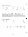
Access Method for Sequential Transfers
Sector Relocation
Bad Sector File Formal
RL01/RL02 Disk Drue-Rear View
Approved Electrical Plugs and Receptacles
Pouer Panel Grounded to Building Frame
Power Panel Grounded to Metal Plate .
\i
Page
-2
-3
-5
'
-7
-X
2-5
2-6
2-7
2-8
FIGURES (COM )
2-6
2-7
2-8
2-9
2-10
2-1 I
2-12
2-13
2-14
2-1 5
2-16
2-1 7
2-18
2-19
2-20
2-21
2-22
2-23
2-24
3-1
3-2
3-3
4-1
4-2
4-3
4-4
4-5
4-6
4-7
4-8
4-9
5-1
5-2
5-3
5-4
5-5
5-6
5-7
5-8
5-9
5-10
5-1 1
5-12
I v p i c a l 60 H/ Power Svstcm
Typical 50 Hz Power System
Split Phase (2-Phase) Power System ...
Three Phase Y Power System
R L I I Component Lav out
R l . l I Base and Vector Address Jumper Configuration
R l . l I P i i o r i t v Jumper Assemblv Connections
R l . l 1 Controller I n s t a l l a t i o n
R L V I 1 Bus Interlace Module ( M 8 0 I 4 ) (Component Side)
R L V I 1 Base Address Switch Settings
R L V 1 1 Vector Address Sw itch Settings
R L V I 1 Drive Module ( M 8 0 I 3 ) ....
H9273 Backplane Grant Prioritv Structure
RL8-A Jumpers
'.
H950 Shipping Package
RLOI/RL02 Cabinet Installation
RLOI/RL02 - Covers Removed
RLOI/RL02 Disk Drive - Rear View
RLOI/RL02 Disk Drive - Front View
RLOI/RL02 Disk Drive - Hxposed Drive Logic Module
RLOI/RL02 Disk Drive - Front View
"
RLOI/RL02 Disk Drive - Rear View
Cartridge Loading Procedure
CS Register ....
BA Register
DAR - Seek Command
DAR - Read/Write Data Command
DAR - Get Status Command
MPR - Status Word
MPR - Three Header Words
MPR - Used as a Word Counter
Register Summarv
Command Register A During a Seek Command
Command Register A During A Read/Write Data Command
Command Register B
Break Memory Address Register
Word Count Register
Sector Address Register
Error Register
Silo Buffer lor Status Word I
Silo Butter tor Status Word 2
Silo Butter tor Header Words
Register Summarv
Maintenance Mode Bit .
\ ii
2-9
..2-10
..2-10
..2-10
2-11
2-13
214
2-15
2-17
2-17
2-1 X
2-19
2-19
2-21
2-23
2-25
2-26
2-27
2-28
2-29
3-1
3-2
3-5
4-2
4-4
4-5
4-6
4-6
4-7
4-X
4-9
4-10
5-3
5-3
5-4
5-5
5-5
5-6
5-6
5-7
5-8
5-10
5-11
..5-17
TABLES
Table No.
I -1
1-2
I-3
I -4
2-1
2-2
2-3
2-4
2-5
2-6
2-7
2-8
2-9
2-10
2-1 1
2-12
4-1
4-2
4-3
5-1
5-2
5-3
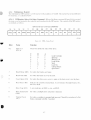
I itk
Reference Documents
RL01/RL02 Disk Dn\e Physical and Environmental Specifications
RLOI/RL02 Disk Drive Operational Specifications
RLUI K/RL02K Disk Cartridge Specifications
Saleable RL01/RL02 Subsystem Options
Saleable Cabinet Options
Diagnostic Catalogs and Indexes
R l . f l - B a s e d Diagnostics
R l . l 1 Diagnostic Kit Numbers
RL1 1 Diagnostic Components
User Documents
R L V 1 1 Diagnostic Kit Designations
RLX/RL01 Diagnostic Kits
RL8/RL01 Diagnostic Components
RLX/RL02 Diagnostic Kits
RL8/RL02 Diagnostic Components
Controller Addressable Registers
RLI 1/RLV1 1 Controller Commands
Errors
RL8-A Instruction Set
RLX-A Controller Commands
Errors .
Vlll
Page
1-1
1-4
I l l
1-12
2-3
2-4
2-3 1
2-31
2-31
2-31
2-33
2-33
2-33
2-34
2-34
2-35
4-2
4-12
4-16
5-1
5-2
. .5-19
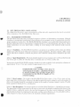
CHAPTER 1
INTRODUCTION
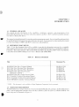
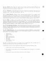
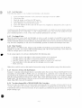
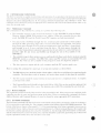
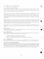
1.1
PURPOSE AND SCOPE
This manual provides information on the capabilities, installation, operation, and programming of the
RLOI/RL02 Disk Suhs>stem. The basic subsystem comprises one RL1 I . R L V 1 I or RLXA controller and up to
four RLOI or RL02 Disk Drives.
This manual is intended primarily for operating and programming personnel. Service should be performed only
by qualified Digital field engineering and maintenance personnel. A prerequisite for understanding this manual
is a basic knowledge of PDP-8 and PDF-1 1 processors and peripherals.
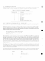
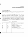
1.2 REFERENCE DOCUMENTS
Table 1-1 lists the documents that will be available to provide the information necessary for a complete
understanding of the function, theor> and maintenance of the RL01/RL02 Disk Drives and the R L V 1 1/RL8-A
Controllers. The Unibusand LSI-1 1 Bus are described m the POP 11 Bus Handbook (EB-17525). The Omnibus
is described in the PDP8IA Minipmccsxor User's Manual (EK-8A002-MM).
Table 1-1
Reference Documents
Title
Document No.
RL01/RL02 Disk Drive Technical Manual
RLOI Disk Drive Illustrated Parts Breakdown
RL02 Disk Drive Illustrated Parts Breakdown
RLOI/RL02 Disk Subsystem P r e v e n t i v e
Maintenance Manual *
RL01/RLU2 Disk Drive Pocket Service Guide
RL1 I Controller Technical Description Manual
RLV1 1 Controller Technical Description Manual
RL8A OMNIBUS Controller Technical Manual
EK-RJL012-TM
EP-OOOI6-IP
EP-00016-IP
EP-00008-PM
EK-RLOI2-PG
EK-ORLII-TD
EK-RLV11-TD
EK-ORL8A-TM
* NOTE - This document is onlv available to Digital Equipment Corporation Service personnel.
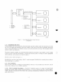
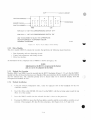
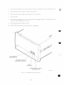
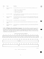
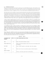
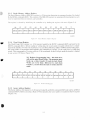
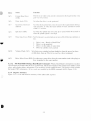
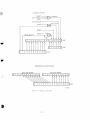
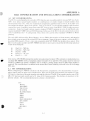
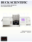
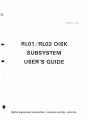
1.3 SUBSYSTEM DESCRIPTION
The RL01/RL02 mass storage subsystem is based on the RLOI K/RL02K disk cartridges, the RL01/RL02 drive
unit(s). and an appropriate controller such as the RL1 I (PDP-1 1). RLVI 1 (LSI-I 1). or RL8A (PDP-8). The
basic subs) stem is illustrated in Figure 1 - 1 .
I I
/s.
CO
CONTROL
UNIT
RL11
RLV1 1
RL8A
CU/DRIVE INTERFACE
I/
(DRIVE 0)
o
READ DATA
STATUS
SECTOR PULSES
(DRIVE 1)
V
UNIBUS
OMNIBUS
Q-BUS
GET STATUS
SEEK
WRITE DATA
(DRIVE 2)
c=^
(DRIVES)
O
CZ 1007
Figure 1-1
Typical RL01/RLU2 Mass Storage Subsystem
Configuration
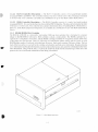
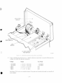
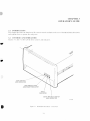
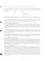
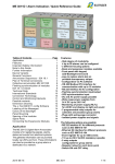
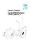
1.3.1 RL01/RL02 Disk Drive
The RL01/RL02 drive unit is built into a chassis that si ides out of the cabinet to allow the operator access to the
top cover for loading and unloading of the disk cartridge. If the stops on the slide are manually released the
chassis can be pulled farther out so that the rear top covercan be removed for servicing. The front panel contains
operator controls and indicators.
The chassis contains a spindle, two read/write heads mounted on a positioner, logic modules, a power supply
with an ac power cord and circuit breaker, a closed-loop clean air system, a cooling air system, appropriate
safety interlocks, and connectors for the I/O cable(s),
The drive unit is shown in Figure 1-2.
The RL02 drive unit has a label reading "RL02" on the front panel. The RLU1 drive currently does not have a
label identifying it as an R L O I .
1.3.2 RL Controllers
There are three controllers available lor the RL01/RL02 subsystem. All can handle up to tour drives and all
feature Direct Memory Access ( D M A ) operation.
1.3.2.1 RL11 Controller Description — The R L I 1 Controller consists of a single, hex-height Small
Peripheral Controller (SPC) module designated M7762. It is used to interface the drive with the PDP-1 1
Unibus. The data is formatted in 16-bit words. This controller can handle any combination of up to four RLOI
and/or RL02 Drives.
1.3.2.2 RLV11 Controller Description — The R L V I I Controller consists of two quad-height modules
designated M80I3 and M8014. This controller interfaces the drive with the LSI-1 I Bus. The data is formatted
in 16-bit words. This controller can handle am combination of up to four RL01 and/or RL02 Drives.
1.3.2.3 RL8A Controller Description — The RL8A Controller consists of a single, hex-height module
designated M8433. It is used to interface the drive with the PDP-8 Omnibus. The data can be formatted in either
8-bit bytes or 12-bit words. This controller has a jumper-determined choice of handling RLOI or RL02 Drives.
However, in the RL02-jumpered configuration, it can handle an\ combination of up to lour RLOI and/or RLU2
Drives.
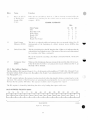
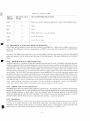
1.3.3 RL01K/RL02K Disk Cartridge
The RL01K or RL02K is a removable, top-loading 5440-t\pe disk cartridge that is formatted in a manner
unique to the RL01/RLU2 subsystem. Both cartridges contain a single platter. The R L O I K cartridge has a
capacity of 5.2 megabytes of user data, and the RL02K cartridge will hold 10.4 megabytes of data. Both sides
of the platter are used for data. There are 256 tracks on each RLOI K platter surface and 5 12 tracks on each
RL02K platter surface. Each track is divided into 40 sectors. Each sector contains 256 bytes of data. The last
track of the last surface is reserved lor the cartridge serial number and bad sector information. Head positioning
servo information and header information are prerecorded at the factory and cannot be reformatted in the field.
This information, along w ith the data, is read by the read/write heads but the internal logic of the drive unit
protects the servo and header information from being overwritten.
f-jjHiiv 1-2
RLOI/RL02 Disk D n \ c
1-3
1.3.3.1 [nterchangeability -The RL01K and RL02K Disk Cartridges are not functional!) interchangeable
although thev are p h x s i c a l K interchangeable. It is possible to mount an R U ) 1 K. cartridge on an RL02 d r i v e , loi
example, hut proper operation w i l l not occur. An RL01K cartridge w r i t t e n on an R1.01 unit can he read on anv
other RLOI unit even if that unit is controlled bv a different l\pe of controller. The onlv limitation to this
inlerchangeabiliu is that it an RL8A controller is used to w r i t e data and the cartridge is to he used on a d r i \ e
controlled h\ an RL1 1 or an R l . Y ] 1 controller, the RLSA must use an 8-bit b\te mode of operation.
An RL02K cartridge u mien on an RL02 unit can he read on an\ other RL02 unit ( a s s u m i n g the same conditions
mentioned abo\e).
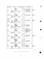
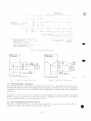
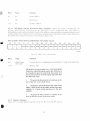
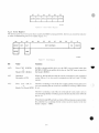
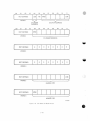
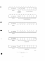
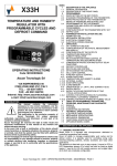
1.3.3.2
Sector Format — As shown in Figure 1-3. each sector contains:
Ser\o information tor head positioning
Header (address) information
Data - 128 words of 16 bilb each, or
256 hues of 8 bits each, or
170 \\ords of 12 bits each
Only the data portion of a sector can be written bv the user. The servo and header information is protected bv the
drive logic and controller to ensure disk integrity and cannot be written in the tick!
Each sector stalls \\ ith a sector pulse that is produced by a sector transducer mounted on the drive unit. It senses
the sector notches that are machined into the hub of the disk cartridge.
During the time that sector notch passes by the sector transducer, the heads detect tw o servo pulse bursts ( S 1 and
S2) that are prerecorded on the platter. These servo bursts are used by the drive logic for head positioning.
Following the servo pulse bursts is the header. It consists ot:
•
•
•
A
A
A
A
A
preamble of three \\ords - 47 "0" bits and one " 1" bit
word that contains the address - sector, head, and cylinder
word of all /eroes
word containing information created b\ the Cyclic Redundancy Check (CRC) logic
one-word postamble of all /eroes
Following the header is the user writable data area. It consists of:
•
•
A preamble of three words - 47 "0" bits and one " 1" hit
Data ( 1 2 8 words of 16 bits or 256 bvtes of 8 bits or 170 words of 12 h i t s )
A word containing CRC-generated information
A one-word postamble of all /ero bits
Following each sector is a period of idle time that is simply a wait tor the next sector pulse.
In addition to the data tracks, there are tracks both inside and outside of the data area that contain unique servo
signals that define those areas as guard hands. II the read/write heads attempt to enter a guard band, the d r i v e
logic causes the positioner to retreat from the guard band and return to the data area.
The disk has a nominal rotational speed of 2400 rev/min. Therefore, the time tor one revolution is 25
milliseconds. Since the revolution is divided into 40 sectors, the duration of each sector is 625 microseconds.
This 625 microsecond period is divided into non-data (sector pulse, header, idle time) time and data time. The
data time period is 500 microseconds. Thus, the data is transferred in 500 microsecond bursts that occur every
625 microseconds.
1-4
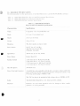
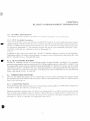
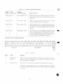
1.6 KL01/KL02 SPECIFICATIONS
The tollouing tables list the specifications ol the RLOI/RL02 drives and the Rl 01K.RL02K cartridges.
Table 1 - 2
Table 1-3
'I'ahle 1-4
RLOI RI.02 Disk Drive I'hvsical ami Lnv ironmcnlal Specifications
RLOI RI.02 Disk Drive ()]vrationul Specifications
Rl OIK Rl 02K Disk Cartridge Specifications
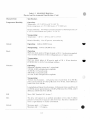
Table 1-2 KL01/KL02 Disk Drhe
Physical and Kn> ironinental Specifications
Characteristics
Specifications
Width
Compatible vuth 19 inch RHTMA rack
Depth
63.5 cm (25 in) behind be/el
Height
26.52 cm ( 10.4-4 in)
Weight
; 34 kg (75 Ih)
Mount in;:
The drive mounts on chassis slides
Power Source
90-127 Vac (47.5-63 H/l
180-256 Vac (47.5-63 H/)
(Manuall\ selectable)
Input Power
160 W max at I 15 Vac. 60 H/
Power Factor
Greater than 0.85
Startinii Current
3.5A (mis) max (it 90 Vac/47.5-6.3 H/
5.0A (rms) max (a 127 Vac/47.5-63 H/
I.75A (rms) max (n 1X0 Vac/47.5-63 H/
2.5A (rms) max (a 254 Vac/47.5-63 H/
Heat Dissipation
546 Btu/hr max
Power Cord and Connector
A molded line cord compatible w i t h the drive operating voltage and the S6 I
power control lor 120 Vac is attached to the drive The power coal is 2.74 in
(9 ft) long and the plug is Nl-.MA 5-15P.
The 230 Vac plug to be attached to high voltage drives is NF:MA 6-I5P.
Safety
The RLOI/RL02 Disk Drive is UI. listed and CSA certified.
Interlocks
Interlocks are used where potential e x i s t s tot damage to drive, media,
operators, or service personnel.
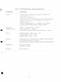
Table 1-2 RUM/RL02 Disk Drhe
Phxsical and Environmental Specifications (Cont)
Characteristics
Specifications
Temperature/Humidit)
Operating:
Temperature: 10° C (50° F) to 40° C (104° F)
Derate temperature at 1.8° C/KKK) meters (1° F/IOOO feet)
Relati\e H u m i d i t y : 10 to 90 percent v. ith maximum \\et bulb temperature 28°
C (82° F) and minimum dew point 2° C (36° F)
Nonoperating:
Temperature: -4()c C (-40° F) to 66° C ( 1 5 1 ° F)
Relative H u m i d i t y : 10 to 95 percent, noncondensing
Altitude
Operating:
2440 m (8.000 I t ) max
Nonoperating:
Shock
9144 m (30.000 ft) max
Operating:
Half sine shock pulse of 10 gravity peak of 10 ± 3 ms d u r a t i o n applied
once in either direction of three orthagonal axes (3 pulses t o t a l )
Nonoperating:
Hall sine shock pulses of 40 g r a v i t y peak of 30 ± 10 ms duration
perpendicular to each of six package surfaces.
Vibration
Operating:
Sinusoidal vibration (sweep rate 1 octave/min)
5-50 H/. 0.002 in displacement amplitude
50-500 H/. 0.25 gravity peak
500-50 Hz. 0.25 gravitj peak
50-5 H/., 0.002 in displacement amplitude
Nonoperating:
Vertical Axis Excitation - 1.40 gravity (rms) overall from 10 to 300 H/:
power spectral density of 0.029 g-/H/ from 10 to 50 H/. w i t h 8 dB/octave
rolloff from 50 to 300 H/
Longitudinal and Lateral Axis Excitation -0.68 gravity (rms(overall from 10
to 200 H/: power spectral density of 0.007 g 2 /H/ from 10 to 50 H/. w i t h 8
dB/octave rolloff from 50 to 200 H/
EMI
Meets DEC Standard 102. Section 7.
Dust
The drive w i l l operate in an ambient atmosphere of less than 5 million
particles 0.5 microns or larger per cubic foot of air. The drive is intended to
run in a light industry or cleaner environment.
Attitude
Maximum pitch: ± 15 degrees
Maximum roll: ± 15 degrees
10
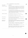
Table 1-3
RL01/RL02 Disk Drhe Operational Specifications
Characteristics
Specifications
General
Linear hit densiix: 147 hits/mm (3725 hits/in) at innermost track
Id hit \\orxls per sector: I 2 X
Numher of sectors per track: 40
Track density: 4.^/111111 ( 1 2 5 / m ) for R L O I K . y.X/mm <250/in) for RL02K
Numher of tracks per surface: 256 for R L O I K . 512 for RL02K
Numher of surfaces: 2
Formatted capacit\ (megabytes): 5.2 for RLOI K. 10.4 for RL02K
Encoding method: Modified Frequency Modulation (MFM)
Transfer Rate
(Unbuffered Values)
Bit rate: 4.1 megabits/second ± I percent
Bit cell w i d t h : 244 ns ± I percent
Word transfer rate (16 hit words): 256 kilowords/second ± I percent
Latency
Rotational frequency: 2400 rev/min ± 0.25%
Average latency: 12.5 ms ± 0.25%
Maximum latency: 25.0 ms ± 0.25%
Seek Time
Average seek time: 55 ms max (85 tracks for R L O I , I 70 tracks lor RL02)
One cylinder/track seek time: 15 ms max
Maximum seek time: 100 ms max (256 tracks for RLO 1 , 5 1 2 tracks for RL02)
Stan/Stop Time
Start time: 45 seconds
Stop time: 30 seconds
Data Format
Refer to Fiuure 1 -3
Table 1-4 KLU1K/KL02R Disk Cartridge Specifications
Characteristics
Specifications
Operating Environment
The cartridge will operate over a temperature range of 4C C to 48° C (40° F to
120° F). at a relative humidity of X to 80 percent. The \vet bulb reading must be
less than 25° C (78° F). Before a cartridge is placed in operation, it should be
conditioned within its cover for a minimum of 2 hours in the same environment as that in which the disk drive is operating. (The abo\e specified ranges
do not necessarily appl\ to the disk d r i \ c ) .
Storage Environment
The cartridge should be stored at a temperature between -40° C to 65° C
(-40° F to 150° F). \\ ith a \vet bulb reading not exceeding 29° C (85° F). For
wet bulb temperatures between 0.56° C and 29° C (33° F^and 85° F) the disk
cartridge v.ill withstand a relative humidits of 8 to 80 percent. The stray
magnetic field intensity shall not exceed 50 Oe.
Dimensions (Cartridge)
The external diameter of the top cover is 38.35 cm ( 1 5 . 1 i n ) .
The external diameter of the protection cover is 37.03 cm (14.58 i n ) .
The external height of the cartridge is 6.19 cm (2.44 in).
Maximum Speed
The rotating parts of the disk cartridge are capable of withstanding the effect
of stress created while rotating at 2.500 rev/min.
Track Geometry
There are 256 discrete concentric tracks per data surface for the RL01 K. 512
tracks per data surface for the RL02K.
Identification of
Data Location
Data Track Identification - Data tracks are numbered by consecutive decimal
numbers (000-255, RL01K; 000-51 1. RL02K) starting at the outermost data
track of each data surface.
Data Surface Identification - The upper data surface is numbered 0 and the
lower surface is numbered I . to correspond with the head numbers.
Cylinder Address - A cylinder is defined as both data tracks (on either
surface) \ \ i t h a common data track identification.
Data Track Address - A 16-bit word defines the data track address. Bits 0-5
define the sector, bit 6 defines the surface, and bits 7-15 define the cylinder
address. This information is in word 1 of each sector's header.
1-12
CHAPTER 2
INSTALLATION
2.1 SITE PREPARATION AND PLANNING
This chapter describes power, space, environmental, cabling and safety requirements that must he considered
he lore i n s t a l l a t i o n of the RLOI/RL02 Disk Subsystem.
2.1.1 Environmental Considerations
The RL01/RL02 Disk Subsystem is designed to operate in a business or light industry environment. Although
cleanliness is an important consideration in the installation of any computer s\ stem, it is particular!) crucial for
proper operation of a disk d r i \ e . The R1.01 K-RL02K Disk Cartridge is not sealed while being loaded and is
therefore vulnerable to dust or smoke particles suspended in the air. as w e l l as fingerprints, hair. l i n t . etc. These
minute obstructions can cause head crashes, resulting in severe damage to the read/write heads and disk
surfaces.
2 . 1 . 1 . 1 Cleanliness - The RL01/RL02 Disk Drives can operate in an ambient w i t h less than one million
particles per cubic foot of air w h i c h are 0.5 micron or larger in diameter. The drive contains a filter system
w h i c h , under these conditions, maintains the particle count w i t h i n the cartridge below KM) particles per cubic
foot.
2.1.1.2 Space Requirements— Provision should be made for service clearances of I m (36 in) at the front and
rear of the rack or cabinet in which the drive is mounted and 1 m (36 in) at either side.
Storage space for the RUM K./RL02K cartridges should also he made a v a i l a b l e . Hach cartridge has a diameter of
approximate!} 3X cm ( 15 in) and a height of approximate!) 6 cm ( 2 . 5 i n ) .
CAUTION
RL01K/RL02K Disk Cartridges must never be
stacked on top of each other. A designated shelf area
-or specially designed disk cartridge storage unit is
recommended (see the DIGITAL Supplies an'' Accessories Catalog).
2.1.1.3 Eloor Loading-The w e i g h t of the RL01/RL02 Disk Drive alone is 34 kg (75 I n ) , w h i c h w i l l not
place undue stress on most floors. However, the added weight of the rack or cabinet as w e l l as the number of
drives to be installed should be considered in relation to the weight of existing computer sy stems. Possible
future expansion should also be a consideration.
2.1.1.4 Heat Dissipation-The heat dissipation of each RLOI/RL02 Disk Drive is 546 Btu/hour m a x i m u m .
The approximate cooling requirements for the entire sy stem can be calculated by m u l t i p l y ing this figure by the
number of drives, adding the result to the total heat dissipation of the other system components, and then
a d j u s t i n g the total figure to compensate for personnel, cooling system efficiency, etc. It is advisable to allow a
safety margin of at least 25 percent above the maximum estimated requirements.
2 . 1 . 1 . 5 Acoustics- Most computer sites require at least some degree of aeoustieal treatment. However, the
RL01/RL02 Disk Subsystem should not contribute u n d u l y to the merall system noise l e \ e l . Ensure that
acoustical materials used do not produce or harbor d u s t .
2 . 1 . 1 . 6 Temperature- The RLOI/RL02 Disk Subsystem \\ ill operate over a temperature ranee of 10° C (50°
F) to 40C C (104 C F). The m a x i m u m temperature gradient is 16.6° C (30° F) per hour. The nonoperating
temperature range is from -4()c C (-40° F) to 66 C ( 1 5 1 " F).
2.1.1.7 Relathe Humidity - H u m i d i t y control is important for proper operation of am computer system
since static electricity may cause memory errors or e\en permanent damage to logic components. The
RLOI/RL02 Disk Subsystem is designed to operate \\ ithin a relative humidity range of I D to 90 percent, with a
maximum wet bulb temperature of 28° C (82° F) and a minimum deu. point of 2° C (36° F). The nonoperating
relative humidity range is from 10 to 95 percent, with a m a x i m u m uet b u l b temperature of 46° C ( 1 15° F).
2.1.1.8 Altitude - Computer systems operating at high altitudes may have heat dissipation problems.
Altitude also affects the H y i n g height of read/write heads in disk drives. The maximum altitude specified lotoperating the RL01/RL02 Disk Subsystem is 2440 M (8000 ft). Also, the maximum allowable operating
temperature is reduced by a factor of 1.8° C per 1000m ( 1 ° F per 1000 ft) above sea level. Thus, the maximum
allowable operating temperature at 2440 m (8000 ft) would he reduced to 36°C (96° F).
2.1.1.9 Power and Safety Precautions-The RL01/RL02 Disk Subsystem presents no unusual fire or safety
hazards to an existing computer system. AC power \s iring should be checked carefully, however, to ensure that
its capacity is adequate for the added load as well as for any possible expansion. The RLOI/RL02 Disk Drive is
UL listed and CSA certified.
2.1.1.10 Radiated Emissions- Any source of electromagnetic interference ( E M I ) that is near the computer
system may affect the operation of the processor and its related peripheral equipment. Common EMI sources
that are known causes of failures include:
•
•
•
•
Thunderstorms
Broadcast stations
Radar
Mobile communications
High-voltage power lines
Power tools
Arc welders
Vehicle ignition systems
Static electricity
The effect of radiated EMI emissions on a computer system is unpredictable. Thus, grounding plays an
important role in protecting the circuits used in disk drive subsystems.
To help reduce the effects of known high-intensity EMI emissions perform the following actions:
Ground window screens and other large metal surfaces.
Ensure that the overall computer system is grounded properly (refer to Paragraph 2.1.5. Grounding
Requirements).
Provide proper storage (metal cabinets with doors) for disk cartridges.
">.->
2 . 1 . 1 . 1 1 Attitude/Mechanical Shock-Performance of the RL01/RLQ2 Disk S u b s \ s t e m \ \ ill not he affected
h\ an attitude w h e r e m a x i m u m pitch and roll do not exceed 15 decrees.
The subsNstem is designed to operate while a half-sine shock pulse of I 0 g r a \ i t > peak and 10 ± 3 ms duration is
applied once in either direction of three orthagonal axes (three pulses total).
2.1.2
Options
I he RL01/RL02 Disk Drive can he shipped u i t h various controllers (lor Unihus. Omnihus and L S I - 1 I Bus
computer s\stems), and can he configured tor 1 15 Vac or 230 Vac operation.
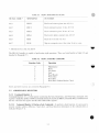
Tahle 2-1 shows saleahle RLOI/RL02 subsystem options. Table 2-2 shows RL01/RL02 cabinet options.
Table 2-1
Saleable KL01/RL02 Subsystem Options
Option
Number
Description
RL01A
RL01 unit, BC20J I/O cable, chassis slide and mounting hardware
RL02A
RL02 unit, BC20J I/O cable, chassis slide and mounting hardware
RL01-AK
R L O I - A (drive), RL01K-DC (cartridge)
RL02-AK
RL02-A (drive). RL02K-DC (cartridge)
RLO IK-DC
RLO I Data Cartridge
RL02K-DC
RL02 Data Cartridge
RLI I-AK
RL01-AK. RL11 Controller. BC06R, terminator
RL2I I - A K
RL02-AK. R L 1 1 Controller. BC06R. terminator
RLVI I-AK
R L O I - A K . R L V I I Controller, BC06R. terminator
RLV2I-AK
RL02-AK. R L V 1 1 Controller. BC06R. terminator
RL8A-AK
R L O I - A K . RLX-A Controller. BCXOJ. terminator
RL28A-AK
RL02-AK, RL8-A Controller. BC80J, terminator
2-3
Table 2-2 Saleable Cabinet Options: (Includes skins, doors, covers, trim, and power controllers)
T> pe
Volts
Dwg
Remarks
H950
1 10
220
] 10
220
H960-BC
H960-BD
H967-BA
H967-BB
Includes five 26.67 cm ( 10.5 i n ) high panels
26.67 cm ( 1 0 . 5 i n ) cover panels ( H 9 5 0 O A ) must he ordered it
required.
1 10
H9603-ED
S\VLB w i t h H9514-B top covers
220
1 10
H9603-EE
H9601-ED
D\\ LB \ \ i t h H 9 5 I 4 - A top covers
220
1 10
H9601-EE
H9602-EA
SWHB complete hiboy cabinet
220
110
H9602-EB
H9600-EA
DWHB complete hiboy cabinet
220
H9600-EB
H9602-B-O
SWHB option arrangement dvvg.
Order as required.
H9600-A-O
DWHB option arrangement dwg.
Order as required.
H9603-B-O
SWLB option arrangement dwg.
Order as required.
H960I-A-O
DWHB option arrangement dvvg.
Order as required.
H967
H9500
H9500
H9500
Saleable Cable Options: Where an I/O cable length of more than 10 feet is required, order one of the
following:
Order No.
Part No.
Length
BC20J-20
BC20J-40
BC20J-60
7012122-20
7012122-40
7012122-60
6 m (20 1't)
12 m (40 ft)
18 m (60 ft)
Total length of cable(s) from the controller to the last drive must not exceed 30 m (100 ft).
2-4
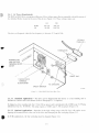
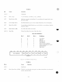
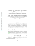
2.1.3 AC Power Requirements
The RL01 or RL02 drive can operate within one of four \oltage ranges thai are manually selected by means of
t w o terminal blocks located at the rear of the device (Figure 2 - 1 ) . These voltage ranges are:
MOM
LO
110
220
100-120
40-105
200-2.%
1X0-210
The drive \\ill operate \\hen the line frequency is between 47.5 and 63 H/.
I/O CABLE
CABLE IN )
NORMAL/LOW
LINE VOLTAGE
TERMINAL BLOCK
COVER
CABLE "OUT"
110/220 VOLTS
TERMINAL
BLOCK COVER
CIRCUIT BREAKER
CZ-1056
I-ILHIIV 2-l
RLOI/RL02 Disk Dnxc-Rcar \Vv\
2.1.3.1 Standard Applications - The drive can be shipped from the factor} as a free-standing unit or
mounted in various racks and cabinets (refer to Paragraph 2 . 1 . 2 . Options).
If shipped as a tree-standing u n i t , the 2.74 m (<J ft) ac power cord is terminated \\ ith a NEMA type 5-15P plug
(DIGITAL Pan No. 90-08938). This plug requires a N H M A tspe 5 - I 5 R receptacle (Figure 2-2).
2.1.3.2 Optional Applications - Operation in the high \oltage range (180-256 Vac) \ \ i l l require reconfiiuirinsi
« the l i n e cord plug~ (Figure
2-1).
•^
*- the terminal block at the rear of the drive and c h a n «
^i n ^
*.
In 50 H/ applications, the line cord plug must be changed (Figure 2-2).
2-5
SOURCE
PLUG
USED ON
RECEPTACLE
ALL 120 V TABLE TOP
COMPUTERS S T A N D A R D
POWER
15A
120V LOW CURRENT
CONTROLLER
1 PHASE
DISTRIBUTION
861 F
120V
120V
TU10 UNITS MOST
N t M A t B 16P
5 1SH
DEC # 90 08938
12 05351
120V T E R M I N A L DEVtCES
yv
W
120/208V
ALL 120V S T A N D A R D
30A
3 PHASEY
HUBBEL
#261
1
I »^
CABINET MOUNTED EOPT
T j
QW
,26,0
W
V^
J
g
NEMA it L6 30P\^_^/
DEC* 12 11193
L6 30R
1 2 1 1 1 94
X.
G
S~
2 PHASE
\
&/
120/208V
3 PHASE Y
#2411
I"
W\
/
NEMA » L14 20P\__^x^
#2410
L14 20R
DfcC * 12 1 1046
Y
1211
Gx
X
1 20/208V
3 PHASE Y
HUBBEL
POP 11/46 PRO
POWER
CONTROLLER
861 A
X
#261 1
N^^^Xw/
N E M A * L21 20P
-.
60 H; RM 10 DRUM
foo^j
#2610
60 Hz RPO2/HP03/
W\"C^> /
RP04, RP06 RP06
L21 20R
1211210
2
^^
Y.<Z3\
^^^ J
DEC » 12 11209
120V
CESSOR CABINET ONLY
Y
046
G
r • t)
V
\
V Cl> /
^^^^'w
Y /^*^^\
20A
> \
(0 0)
JJ
f^,
<
fC\^}
or
HUBBEL
861 C
X
X
120/208 240V
20A
20A
^)
V
POWER
CONTROLLER
Z
ALL 240V TABLE TOP
COMPUTERS
240V
STANDARD LOW CURRENT
16A
240V DISTRIBUTION
1- PHASE
MOST 240V TERMINAL
DEVICES
6 1BR
12 11204
NEMA * 6 IBP
DEC » 90 08853
240V TU 10
X
X
240V
1 PHASE
ALL 240V STANDARD
ftP)
20A
HUBBEL
V ^
DEC# 12
V
*/
#2320
Y
#2321
^^__^//
N t M A « L6 20P
"©,
3 PHASE Y
X
^
NEMA » — NOT NEMA
Y
NOT NEMA
G
a^
V/^v
W
/^\
7
1211269
DEC t 12 09010
1 PHASE
HUBBEL
#2811
1 '
^-~^
L21 30P
DEC 12 12314
z
^
\
»(&o Q )
v ^^ y
NEMA
#2810
50 Hi RP02/RP03/
RP04
\X
/
/
"* / W
60 Hi RM10 DRUM
G
s—\
f^*\
120V
861 B
—-S
x
30A
EQUIPMENT
/
Z
\z
240/4 16V
20A
POWER
CONTROLLER
L6 20R
12 11191
11192
/"
<V
^V
CABINET MOUNTED
V^yv
^^_^/
PDP11/70
PROCESSOR
POP 11/70MEM
POWER
CONTROLLER
VAX 11/780
861 D
PROCESSOR
z
L21 30H
12 12315
CP-I968
Figure 2-2
Apprtncd lilectriciil Pluys and RecepUides
2-6
2.1.4
Installation Constraints
The route from the r e c e d i n g area lo the istallation site that the e q u i p m e n t u
adxance to ensure prohlem-free d e l i v e r s A moils: the considerations are:
•
2.1.5
travel should be studied in
Height and loeaiion of load ins: doors
Si/e. c a p a c i t y , and a \ a i l a h i l i l \ ot e l e v a t o r s
N u m h e r and si/e ol aisles and doors en route
Bends or obstructions in hallways.
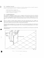
Grounding Requirements
Each cabinet of a D I G I T A L computer system is equipped w i t h ground lug terminals thai should be
connected to a low-impedance earth ground by No. 4 AWG (5 mm/0.20 in) copper wire or stranded
No. 4 AWG welding cable. A Burndy QA4C-B solderless lug (or equivalent) is recommended for terminating the cable. D I G I T A L supplies a standard grounding conductor with each I/O and memory cabinet.
When two cabinets are bolted together, D I G I T A L bonds them electrically with a No. 4 AWG conductor (5 mm/0.20 in) or by several copper mesh straps connected between the cabinet frames. Use the
green/yellow conductor in the power cord for safety ground connection.
The green/yellow grounding wire in the power cable must be returned to ground at the system power
distribution panel. Note that the green/yellow wire is a non-current carrying conductor, not a neutral
conductor.
For information about system grounding considerations, see the DIGITAL Site Preparation Guide (EKOCORP-SO-003).
08-0717
HJ:niv 2
Rmei Kind Grounded 'lo Buildinj: Frame
2-7
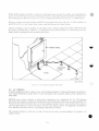
Where neither scheme is possible. a metal area (comprising tlie power panel, the c o n d u i t , and a metal plate) ot
at least I nr ( 1 0 f t - ) that is in contact w i t h masonrv must he connected to the green ground u i r c ( F i g u r e 2 - 4 ) .
The connecting w ire must not exceed 1.5 m (5 It) in length and should he at least a No 12 AWG ( 2 m m ) .
When two cabinets are bolted together. D I G I T A L bonds them electrically w i t h a No. 4 -\\\'G conductor (5
mm/0.20 in) or In several copper mesh straps connected between the cabinet frames.
A l t e r the grounding svstem is installed, it is ad\ isable to take a voltage reading between the cabinet frame and
the nearest grounded object. NBFL' No. 70 (published b\ the National Bureau ot U n d e r w r i t e r s ) provides
further details regarding preferred grounding procedures
0 8 - 0718
Figure 2-4
Power Kincl (iiouiuk-d lo \lcl.il PI.no
2.2 AC CABLIM;
Computer equipment requires a power source w ith a m i n i m u m number of voltage and frequency disturbances.
Line voltage disturbances greater than I/4 c\cle (measured at the receptacle during s\stem operation) are
undesirable.
DIGITAL power wiring conforms to Underwriters Laboratories. Inc.. Handbook UL No. 47S. National
Llectrical ("ode standards, and the t v p e I I requirements of the National Fire Protection Association ( N F P A 70).
This means that in the United Slates the w ire used as equipment ground is green, or green w ith a v e l l o w stripe; it
carries no load current (except in emergencv). hut does carrv leakage current. No equipment is permitted to
leave DIGITAL that does not h a v e a grounding connection to its frame.
The grounded conductor is light gre\ or white. It must not be used to ground equipment. Its purpose is to
conduct current.
2-8
Lines 1. 2. and 3 in a tvpical 60 H/ pouei system (Figure 2-5) are represented bv black, red. and blue w ires,
respectively, and phase rotation is in that order.
CAUTION
Where no grounded wire can be guaranteed, it must
not he assumed. There are some 115 V/60 Hz systems within the L'nited States where neither side of
the line is grounded ( 1 1 5 V 3-phase delta).
MAIN C I R C U I T
/ — BR F I
y
PHASE A ^_ ^A
I
1
120V
1
PHASE 8 ^
^T
/
(
1
208V
1
MAIN SUPPLY
TRANSFORMER —
(ONlr S E C O N D A R Y S H O W NM))
ER OR
CUT-OFF CONTACTOR
\
208V
208V
\ ^1
'
120V
1
PHASE C ^_ -x
t
12OV
|
NEUTRAL
FRAME GROUND
\
J,
I
NOTES
A THE NEUTRAL C
TOR SHOULD BE GROUNDED AT THE MAINS
SUPPLY TRANSFORMER
AND IF REQUIRED BY L(" i r A i . i T w n R i T i F ^ A T T n e n i c T O i n i j T i n N
)
)
ro
/
|
SINGLE PHASE
(TYPICAL 1
)
)
LOADS
)
1
J
J
TO THREE
P H A S E LOADS
rMLALI
PANEL AND E L S E W H E R E
B
THE FRAME GROUND CONDUCTOR MAY CONSIST OF ELECTRICAL
METALLIC CONDUIT OR
R A C E W A Y IF APPROVED 0Y LOCAL A U T H O R I T I E S
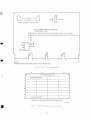
Figure 2-?
Typical 60 H/ Power System
Figure 2-6 shows a tvpical 50 H/. power system.
Two types of" power systems can be used to provide power to the NEMA type LI4-20R receptacle. The type
shown in Figure 2-7 is referred to as split-phase (or 2-phase 180 displaced) 120/240 Vac. It comprises a
center-tapped transformer w i t h 120 Vac between the center tap and either of the two legs. 240 Vac exists
between the two outside legs.
The second t>pe (Figure 2-8) is referred to as 3-phase Y ( 1 2 0 displaced) 120/280 Vac. The 120 Vac exists
between neutral and any of the three other legs ( X . Y. or Z). and 208 Vac exists between any two of the outer
legs ( i . e . . between X and Y. X and Z, or Y and Z). Although Figure 2-8 shows the X and Y connections as the
two phases used for the receptacle, any two of the three phases shown can be used.
The ground terminal on the L14-ZOR receptacle w ill normal!) have a green screw . the neutral terminal w ill be
w h i t e or silver, and the "hot" terminal w i l l be brass covered.
2 ')
MAIN CIRCUIT
ER OR
/— BR
/
PHASE A ^_ -^Jf_
CUT-OFF CONTACTOR
m
, . , - .
(
380/416V
220/240V
PHASE B ,-
\
MAIN SUPPLY
i
TnArj"rontgicr
(ONLY S E C O N D A R Y S H O W N )
'
*C
K
ft
/
580/
416V
>-)
\
r
i
380/
416V
1 1
220/S40V
PHASE C ^_
22O/240V
NEUTRAL
i
SAFETY EARTH GROUND
sr
\
NOTES
A THE NEUTRAL CONDUCTOR SHOULD BE CONNECTED TO EARTH
GROUND AT THE MAINS SUPPLV
TRANSFORMER IF REQUIRED BY LOCAL AUTHORITIES IT MAY ALSO BE
EARTHED AT THE
DISTRIBUTION PANELISJ AND ELSEWHERE
B
TO
)
)
)
)
1
,— ''
„
'
SINGLE PHASE
(TYPICAL)
-
LOADS
,
*
'
TO THREE
PHASE LOADS
(TYPICAL)
THE SAFETY EARTH GROUND CONDUCTOR MAY CONSIST OF
ELECTRICAL METALLIC CONDUIT OR
RACEWAY IF APPROVED BY LOCAL AUTHORITIES
h'iuurc 2-d
POWER LINE
TRANSFORMER
I \ p i c a l 50 H/ P » u \ ^ i SssiL'in
1
pro
POWER LINE
TRANSFORMER
|7]\
1
£
^
-L
1 v ~-
CD
iaov
<F
240V
WHITE
OR GRAY
i
T
^ ^L
120V
^
^
\/
a
1 ,/
GREEN
SAFETY
/[\
2O8V
/
jA~-
120V
\1/
120V
GREEN
SAFETY GROUND
G
GROUND
±
( A l 120 240V SPLIT-PHASE (TWO PHASE)
(Bi 120 208V THREE PHASE
I-iiHirc 2-~*
Spin I'h.isc i 2 ph.isL'l Poucr S x s i o n i
F-'isiurc 2-X
11-2294
Thix'c Ph.iM.' > l'm\i. L i Sssicin
2.3 INSTALLATION - (JKNKRAL
The controller should he installed first. tolUmed h\ the d r i v e l s ) . N e x t , the diagnostics should he run to
demonstrate that the suhs\sieni is Umciioninii properU 01 to diagnose an\ prohlems. Paragraph 2.4explains the
installation of the R L I I Controller, Paragraph 2.5 deals u ith the RLV'l 1 and Paragraph 2.6 describes RL8A
installation.
Paragraph 2.1 contains instructions to i n s t a l l the unit and Paragraph 2 S e x p l a i n s acceptance testing and
contains separate paragraphs for each of the three controllers Paragraph 2.9 describes the use of the M U 31 2
bootstrap module that ma\ be used on RI. 11-based s\stems.
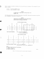
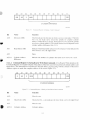
2.4 R L 1 1 CONTROLLKR INSTALLATION
The R L . I 1 Controller (M7762) is a single hex-height module that is installed in a hex-height SPC slot.
Connector J l connects the controller to the drive bus (Figure 2-9).
2-10
Ot the 21 junipers on the R L i 1 Controller, t n e are used tor tactor\ test purposes. The r e m a i n i n g 16 are lor
address selection:
\V 1 -\V6
\V7-\V 16
VECTOR ADDRESS ( 160)
BASE ADDRESS (774400)
NOTE
A logical one is represented b\ the presence of a
jumper uire.
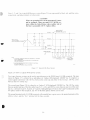
The Unibus priorit) plug sets the prioriu lor hus requests. Eor the R E I I siihs\ stem, bus requests are at pnoi i t \
level 5 (BR5/BG5). (See Figures 2-10 and 2 - 1 1 . )
NOTE
Adjustments on the RL11 are preset at the factory
and are not to he changed in the field.
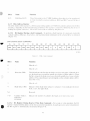
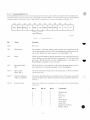
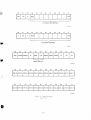
VECTOR ADDRESS SCHEME
I
1
2'7
2'
6
5
2' I 2
M
2
13
2
12
I 2"
0
0
0.0
0
0.0
X
X
X ' x
X
X '
FOR VECTOR ADDRESS
X
2
10
I
2 I 28
9
2?
6
2
6
2B
2"
0
23
22
2'
2°
0
0 1 0
0
1
1
1
0
0
0
0
X
X
»i
W3
W4
W5
W6
W2
X
X
160 - Wa, \A/4, Ws JUMPERS IN
Wi, W^ We JUMPERS OUT
BASE ADDRESS SCHEME
)ie
2"
1
X
I
7
I
2' 6
I
2 1 6 1 2M
213
21
11
2 10
29 | 28
27
.1 . 1.
,
1,
i
o
o | i
o
1
1
X
X -
X
X
W, 2 | W 1 6 W, 6 W 1 4 | W,
W6
0
I
0
26 I 26
24
23 I 22
2'
2°
o|o
o
o i o
o
o
X
X
W9 | W,, W, 0 W , 3 i
X
I
I
FOR BASE ADDRESS 774400 - W, 2 . W, 6 . W, JUMPERS IN
W,. W 9 . W, 0 . W,,. W, 3 . W 1 4 . W, 5 . JUMPERS OUT
NOTE
X'S DENOTE DON T CARE (NOT SELECTABLE)
I S DENOTE JUMPER IN
O S DENOTE JUMPER OUT
Figure 2 - 1 0
K L I I Busc And Vector Address Jumper Cont'igurution
2-13
cz-2004
16151413121110 9
O O Q O Q O-O Q
O <•> 0-0 <l> O <O
1 2 3 4 5 6 7 8
PRIORITY JUMPER PLUG FOR
BUS REQUEST LEVEL FIVE (5)
PLUG PIN NUMBER
SIGNAL NAME
UNIBUS PIN
1
2
BG IN
3
BGOUT
4
UB BG 4
DT2
5
UB B G 4 I N
DS2
6
UBBG 5
DR2
7
U B B G 5 IN
DP2
8
UB B G 6
DN2
9
UB BG 6 IN
DM2
10
UB B G 7
DL2
11
UB BG7 IN
DK2
12
BR
13
UB BR 4
DD2
14
UB BR 5
DE2
15
UB BR 6
DF2
16
UB BR 7
DH2
I-ILUMV 2 \\
K l . l l I'nonts .lunipci AsscmhK Connections
To install the controller:
I
Rcimne the M77d2 module from its shipping container and examine it for any p h y s i c a l damage.
~.
If a priority level other than 5 is required, obtain an appropriate priority jumper assembly or set up
the priority jumper assembly (item I . Figure 2-9) using Figure 2-1 I as a guide. The vector and base
address junipers W 1 - W I 6 are for I60 and 774400, respectively. If the subsystem configuration
requires other than standard addresses, set the jumpers up as shown in Figure 2-10. Physical location
of these jumpers is shown on Figure 2-9.
3.
Install the ribbon cable (BC06R-XX) \\ ith the red indicator stripe to the right and the smooth side
lacing the viewer when view ing the component side of the controller as shown in Figure 2-12. Dress
the cable as necessar\.
2-14
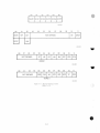
RLV11 BUS INTERFACE MODULE (M8014)
COMPONENT SIDE 1
MSB
BUS ADDRESS SWITCH
LSB
MSB
VECTOR SWITCH
LSB
f
n
f\
A
V
CZ-2006
Figure 2 - M R L V I I Bus Interlace Module
( M N O I 4 ) (Component Side)
-LOGIC ELEMENT
E23-*-
1
!
j 2
7
15
2'
4
2'
4
3
HARDWIRED
1
I
i
1
1
1
2'2
1
2 '2
10
o
4
2
9
28
•
5
2 2" 2
0 0 0
3
1
1 0 0
1 0 0
10
9 8 7
6 5 4
2 1
L . ._!_
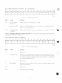
MSB
EBASE ADDRESS
3
2 7 26
BINARY VALUE
•
SWITCH
SV
NUMBER
LSB
FOR EACH "O" SET THE CORRESPONDING SWITCH "OFF"
FOR EACH "1" SET THE CORRESPONDING SWITCH "ON
USE THIS SCHEME TO SELECT THE APPROPRIATE BASE
ADDRESS IF A DIFFERENT BASE ADDRESS IS REQUIRED
CZ 2034
Figure 2 \4
R L V I I Base Address S w i t c h Settings
2-I7
— LU
LOGIC
VECTOR ADDRESS
•
D 1 M A pV
2
7
v A i i ir
SWITCH NUMBER
•
6
1
26
7
6
2e
6
0
3
2
i
2
1
2" 2
1 o
2
n
5
4
3
2
1
2 1 2°
.
MSB
FOR EACH ' 0
ELEMENT
-HARDWIRED
J
LSB
SET THE CORRESPONDING SWITCH "OFF"
FOR EACH "1" SET THE CORRESPONDING SWITCH
"ON"
USE THIS SCHEME TO SELECT THE APPROPRIATE
VECTOR ADDRESS IF A DIFFERENT VECTOR
ADDRESS IS REQUIRED
F-igure 2 - 1 5
cz 200?
R I . V I I Vector Address Switch Settings
2.5.2 Drive Module
The drive module (M8013) contains the circuitry that performs the following major functions:
•
Data formatting and error detecting circuits
Control microsequencer and liming circuits
Drive bus interface
An illustration of the component side of M8013 is shown in Figure 2-16.
NOTE
Adjustments to the RLV11 are preset at the factory
and are not to he adjusted in the field.
2.5.3 Module Slot Location
Modules M8013 and M8014 must be inserted into the H9273 backplane (Figure 2-17) such that the M8013
module is in the slot closest to the processor. Outside of this one restriction, the two modules can be inserted in
any two unused slots. The controller priority level is based solely on its electrical distance from the
microprocessor module in slot 1.
2.5.4
Module I n s t a l l a t i o n
1.
Using the normal configuration rules, select two adjacent slots in the backplane for the two
controller modules.
2.
Insert the ribbon cable (BC06R-XX) into J l on the MS013 w i t h the red stripe edge toward the top
(Row A) of the module.
3.
Insert the MX013 module into the selected slot that is closest to the processor.
4.
Examine the M8014 to insure that the base address switches and the vector address switches are set
correctly. Check jumpers Wl thru W4 for correctness. See Figures 2-14, 2-15 and 2-16.
2-18
r^
{\
ji
W2
VCO POT
CABLE CONNECTOR TO DRIVE
RLV11 DRIVE MODULE (M8013)
COMPONENT SIDE 1
JUMPERS W2 AND W4 IN PLACE FOR EPROM USE (PART #()5XB7)
JUMPERS W1 AND W3 IN PLACE FOR MASKED ROM USE ( P A R T #2^0171 2t
W1
0
E49
»0
ROM
W4 W3
OR
EPROM
1
V
A
V
A
A
V
f
V
A
NOTE:
JUMPERS ARE ZERO OHM COMPOSITION RESISTORS
Hsiurc 2 - } l i
^
CZ-2008
HI \ I I Drive Module <MNUI 5 )
pnoprQcnn Mnniii r
^
HIGHEST PRIORITY
1
\
.
LOWEST PRIORITY
(MODULE SIDE VIEW OF 9 SLOT BACKPLANE)
HsHire 2 I 7
H927.1 Backplane Grant Pnoiilv Struclurc
2-19
5.
Insert ihe MH014 modulo next to the M 8 0 I 3 .
d.
I n s t a l l the transition bracket at the rear ol the cabinet as shown in Hgure 2 - 1 2 . Assemble and i n s t a l l
the t r a n s i t i o n connector.
7.
Connect the other end ol the nhhon cable w i t h the red stripe up.
S.
Appl\ s\siem powci and. u s i n g a suitable measuring d e \ i c e ( i . e . . d i g i t a l voltmeter or equivalent),
\ e r i l \ that the \oltages are w i t h i n the ranges specilied belo\\.
VOLTAOL
RAMIK
TEST POINT
Ground
+ 5 Vdc
4 12 Ydc
-5 Vdc
+4.75 Vdc to - 5 . 2 5 \'dc
4-11.5 Vdc to - 12.5 Vdc
-5.25 Vdc to -4.75 Vdc
AC2
AA2
AD2
A L 1 ( M S O n onl\ )
NOIL
The 5 Vdc is generated on the M8013 nioduk'. It is
not adjustable hut must he w i t h i n specifications for
proper operation. Module replacement is the only
corrective procedure.
V
Measure all voltages between the ground test point and the appropriate voltage test point. It an\
adjustments to the power suppK are necessar\. refer to the appropriate manual.
2.6
KL8-A CONTROLLER INSTALLATION
^ft
2.6.1 Introduction
The RL8-A Omnibus controller module (MX433) contains the f o l l o w i n g logic iLinctions:
•
•
•
Interlace logic
Programmable registers
Silo data storage and control
Data formatting and error detection
Control micro sequencer and timing logic
D n \ e bus interlace logic
NOIL
Adjustments on the RL8-A are preset at the factor)
and are not to he changed in the field.
2.6.2 Module Slot Location
The module can be inserted into an\ unused Omnibus hex-height slot between the CPU and the first memoi\
element. The controller is connected to the tirst drive \ ia a BCXOJ-20 interlace cable. Connections between
d r i \ e s are made using a HC20.I XX ( 7 0 - 1 2 1 2 2 - 1 0 ) cable.
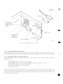
2.6.3
Module Installation
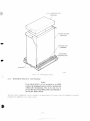
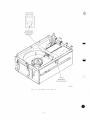
I
Remove the M8433 module (see Figure 2-18) and interface cable (BC80J-20) from the shipping
container and inspect them for physical damage.
2-20
FULL TELESCOPE CAP
(9905446)
5-PANEL FOLDER
(9905975)
CRATING SLAT
(7606858)
CUSHIONED
SHIPPING SKID
STAPLES
H;JIIIV 2 19
2.7.2
HV50 Shipping Package
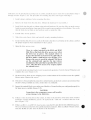
KL01/RL02 Disk Drive Unit Mounting
NOTE
II the RL01/RL02 is to he mounted in an H950
cabinet, the shipping brackets must he retained and
refitted after installation. This is the onh «a> to
pre\ent the dri\e from sliding \\ hile repositioning or
moving the H950 cabinet.
I he d r i \ c IIKIV he shipped in a rack or cabinet as an integral part of a s\ stem or ma\ he shipped in a separate
container lor addition to an e x i s t i n g s \ s t e m .
2-21
It the drive is lo he installed in an existing rack or cabinet, install the chassis slides first as described in Steps 1
through 6 below (Figure 2-20). The procedure tor i n s t a l l i n g the dri\e itself begins w i t h Step 7.
1
Install cabinet stabilizers before mounting the drive.
2
Remove the slides from the disk d r i v e . ( R e t a i n the hardware for reassemblv.)
3.
Install slides into the rack or cabinet using enclosed hardware. Be sure the slides are at the correct
height to permit installation of pop panels (dress panels) upon completion of installation. Also v c i if\
that the slides do not bind on anv hardware used to mount the slide.
4.
Hxtend slides to lock position.
5.
Slide d r i v e onto chassis slides and reinstall security mounting hardware.
6.
Ensure that the disk drive moves easilv on the slides, that there is no binding in the cabinet, and that
the proper height has been maintained tor dress panels.
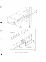
7. Open the drive access cover.
NOTE
There is a safety interlock in the RUM and RL02
Disk Drives that locks the drive access cover when
the drive has no power. The manual release to
bypass this interlock is located on the right side of
the drive under a small access cover (Figure 2-21).
Remove the cover to reach the solenoid. Pull down
on the solenoid and operate the top release
mechanism at the same time to open the drive access
cover. After the drive access cover is open, replace
the solenoid cover.
8.
Loosen the head restraining bracket screw located on the positioner. Turn the bracket 90 degrees and
retighten the screw (Figure 2-21 ).
9. On newer drives there are two shipping screws on the bottom of the unit that secure the spindle/
blower motor. Remove the screws.
10. It the d r i v e is being installed in a dual-drive cabinet that has an interlock system to prevent more than
one drive being extended at a time, ensure that it is connected.
1 I . Inspect the terminal block covers at the rearof the drive. Ensure that they are configured properly for
the input power available (Figure 2-22).
CAUTION
Connection to the wrong power source w ill result in
serious damage to the disk drive.
12. If there is onlv one disk drive in the svstem. or if this is the last drive of the daisv c h a i n , i n s t a l l a
terminator assembly ( D I G I T A L part no 70-12293) in the "cable out" location at the rear ot the
d r i v e (Figure 2-22).
13. If this is an RL1 1 or an R L V 1 I-based system, route the I/O cable BC20J-XX ( D I G I T A L pail no
70-1 2122-10) between the first drive and the transit ion connector. If this is an RL8-A-based system.
route the BCKOJ-20 cable from the RLXA to the first drive.
2-24
SEE
DETAIL
LOCKING LATCH
ACCESS SLOT
SLIDE EXTENSION
RELEASE CATCH
HLUMV 2-20
RI.UI/KL02 CabiiKM IiixUll.H]."!
2-2^
POSITIONER
FRONT VIEW
POSITIONER
RESTRAINING
BRACKET
LATCH
SOLENOID
ACCESS COVER
CZ-2003
l-iyiuv 2-2\
Kl.ni KLU2 - ( overs Rammed
2-26
/O CABLE
(' CABLE IN")
NORMAL LOW
LINE VOLTAGE
TERMINAL BLOCK
COVER
CABLE"OUT"
1 10/220 VOLTS
TERMINAL
BLOCK COVER
CIRCUIT B R E A K E R
CZ 1056
Hs;uix- :-:2
14.
RL01/RL02 Disk U i i \ c - K i M i \ ic\
II this is ;t niul lid rive installation, connect ;m I/O cable from "cable in" ot this drive to the "cable
out" connector of the previous d r i v e . Repeat tor each d r i v e .
NOTE
The total length of cable from controller to the last
drive must not exceed 30 in (100 ft).
15.
Install the proper u n i t select plus: al the front of the d r i v e (Figure 2-23).
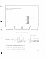
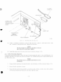
2.7.3
Drive Fix-startup Inspection
To begin the inspection procedure, remove the top cover bv loosening the c a p t i v e screws and l i f t i n g the cover
straight up. Rest the cover on the rear of the d r i v e (Figure 2-24). With the drive power oft and controller power
on. follow these steps.
NOTE
If a problem occurs, consult theRL01/RL02 Techni-
cal Man mil.
1.
Ensure that the positioner r e s t r a i n i n g bracket is not i n t e r f e r i n g w ith the positioner (Figure 2 - 2 1 ) .
2.
Fnsiire that the positioner is home.
3.
Fnsure that the read/w rite head gimbels are not bent or dirt v . ( I I t h e v are d i r t v . clean w ith a s o l u t i o n
of 91 percent alcohol and 9 percent w a t e r and a l i n t - f r e e w iper.
2-27
4.
Ensure that the spindle rot ales I t e e K and Us top surfaces are not d i r t \ . ((lean as described a h o \ e ) .
5.
U n s u i e thai the brush asscmhh is home ( n o t exposed).
d.
Unsure thai the logic modules and connectors are seated firniK .
7.
Turn C B I ON.
X.
Unsure that the spindle rotates s|o\\ 1\ counlerclocku ise for approximate!) 15 seconds and stops. At
this time, the LOAD light \ \ i l l come on
9.
Unsure that the I A l ' U l light is not on.
10
I - n s u r e t h a t the Ian at the rear of the d r i x e is operating.
LOAD SWITCH
AND INDICATOR
UNIT SELECT PLUG
AND READY INDICATOR
FAULT
INDICATOR
WRITE PROTECT SWITCH
AND INDICATOR
CZ 1005
Figure 2-23
RL.OI RL02 Disk Dme-Front \ io\
2-28
DRIVE LOGIC
MODULE
A.C
SERVO MODULE
R/W
MODULE
D C SERVO MODULE
AND TEMPLATE
HjMJK' 2 - 2 4
I.
KI.DI KI.02 Disk l ) n \ c h\pOM.xl DII\L- I oyic Module
Using u suitable measuring device ( i . e . . digital voltmeter 01 e q u i v a l e n t ) , ensure the follow ing d r i v e
voltages are \\ithin the specified tolerances.
\oltajje
Range
Test Point
+ I5UNREG
-15UNREG
-I-5REG
+8REG
-8REG
( + 15.0 to + 1 S . U Vdcl
( - 1 5 . 0 to -18.0 V d c j
(+4.85 to -r5.35 Vdcl
( + 7.7 to +8.3 Vde)
( - 7 . 7 to -8.3 Vdcl
+VUNREG
\ L'NRIXJ
IPS
TP4
TP5
See Figure 2-24 for dc ser\o module location. Test points are located on the mask covering the deservo module.
2-29
2.7.4
I2
\ c r i t > t h a i the WRITE PROTcet sw itch c v c l e s in and out and the indicator l i g h t s up \\ hen the sw itch
is pressed.
13.
Y e n l v t h a t the 1 OAD switch cycles in and out when the switch is pressed. R e t u r n sw itch to the
"out" p o s i t i o n .
14.
Turn oil C B 1 .
15.
R e i n s t a l l the top cover and secure w i t h the c a p t i v e serous.
16.
F.nsuiv t h a t the d n \ e access c o v e r cannot he opened.
17.
Turn C B I on and ensure the d r i v e access covei w i l l open.
Drive Startup Operation Cheek
1.
W i t h the d r i v e power ON. install a scratch cartridge as described in Paragraph 3.3.
2.
Close the cover, press the LOAD s w i t c h and note that:
•
The LOAD light goes out
When the cartridge reaches nominal speed ( a l t e r approximate!) 30 seconds), a brush cvcle
commences. When the brushes h a v e returned home, the read/write heads w ill load and approach
cylinder 0. When the heads h a v e locked onto c v l i n d c r O . the RLADY light w i l l i l l u m i n a t e The
total time lor t h i s process is approximate!) 45 seconds.
3.
Press the LOAD s w i t c h again. The RF.ADY l i g h t should go oft and the read/write heads should
retract to their home position. The spindle should slow dow n and then come to a complete stop alter
about 30 seconds The LOAD light should i l l u m i n a t e w h e n the spindle has stopped.
4.
II the d r i v e startup operation check detailed above is succcsslullv completed ( i . e . . the RLADY
indicator i l l u m i n a t e s ) , run the subsystem confidence tests described in Paragraph 2.S. II there is a
problem, c o n s u l t the Rl.nl 'Rl.02 Tccliiiiml Manual.
2.8 CONKIDKNCK TKSTINC
Confidence testing consists of running the diagnostic programs. Lach diagnostic has a listing that contains
operating i n s t r u c t i o n s Lach l i s t i n g e x p l a i n s svstem hardware requirements, s o f t w a r e e n v i r o n m e n t , w h i c h
features are tested and how ihev are tested, program options and how to select them, how to interpret printouts,
error h a n d l i n g , d e v i c e information tables, dialogue w i t h the Diagnostic Supervisor, and complete operating
instructions. The l i s t i n g s are a v a i l a b l e as hard copv p r i n t o u t s or on microfiche.
The binarv form of the diagnostic programs are av ailable on v arious media, ll is alw av s adv isable to keep a copv
of the RL01/RL02 diagnostic-son a media other than the RLOI K or RL02K cartridge so t h a t the diagnostics can
he loaded through another device it the R l . subsvstem is d o w n .
2-30
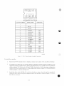
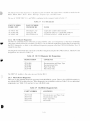
When ordering diagnostic media, l i s t i n g s , manuals, or microfiche, check the current catalog or index tor the
latest revision l e \ e l . The applicable catalogs and indexes are listed in Table 2-3. Unless otherwise specified
when ordering, the latest r e v i s i o n w i l l be shipped.
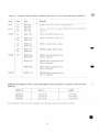
Table 2-3
Diagnostic Catalogs and Indexes
NAME
PDF-1 I
PDF- s
PDF I I
PDF- X
PART M M H K K
Diagnostic S o f t w a r e Components Catalogue''
Software Components Catalogue*
\1 \ 1 N D L C I n d e x (microfiche)
M A I N D H C Index (microfiche)
AV-B021E-TC
AV-OX72B I A
AH-W26P-MC
AH-6572G-MA
Note—Both of these catalogs are available on microfiche (EP-08/11 DC-02).
2.8.1 R U l - K u s c d Diagnostics
The diagnostic package used for an K l . l I / R L O I subsvstem before the release of the RL02 consisted of the six
tree-standing programs listed in 'fable 2-4. There were two revisions. Revision A and Revision B. I hese
programs handled onlv RL01 d r i v e s ( n o t RI.02 u n i t s ) .
Table 2-4
RLll-Based Diagnostics
PAR I N U M B E R
DESCRIPTION
C/.RLAAO
C/RLBAO
C/RLCAO
CZRLDAO
CZRLEAO
C/RLFAO
Controller Test Part I
Controller Test Pail 2
Drive Test Part I
Drive Test Part 2
Performance Exerciser
Drive Compatibility Test
These diagnostics can be run tree-standing, under the Diagnostic Supervisor, m a n u a l l v under XXDP.
chainable under X X D P (except CZRLEAO w h i c h requires manual i n t e r v e n t i o n ) , or under manufacturing
checkout environments such as SLIDE or AC I - I I .
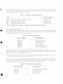
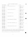
A new diagnostic package is a v a i l a b l e to tesi either an RLOI or an RL02 u n i t . The k i l numbers are sled in Table
2-5 and the contents of the tests are shown in I able 2-6.
There is a new program added to the package named ( /RLMAO. It is used to read the Bad Sector Hie and can
be used to write entries into the field w i liable portion of the Bad Sector Hie. I his program is not a diagnostic
and should not be used as one. It assumes that the svstem is f u n c t i o n i n g propcrlv.
Table 2-5
R L I I Diagnostic Kit Numbers
PART N L M B K R
DESCRIPTION
ZJ2X3-RB
ZJ283-RZ
/J283-PB
ZJ2X3-ER
Documentation and Paper Tape
Documentation O n l v
Paper Tape Onlv
Microfiche Only
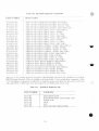
Tablt-2-6
RL11 Diagnostic Components
PART NUMBER
NAME
ITEM
AC-F11 1A-MC
AH-FI I O A - M C
AK-F108A-MC
AK-F109A-MC
AF-FI I 1 A - M O
C/RLGAU COM ROLLER TFST #1
DOCUMENTATION
FICHE
PAPER "I APE #1
PAPER TAPE #2
DECO
AC-FI 15A-MC
AH-l-1 I4A-MC
A K - F I 12A-MC
AK-FI I3A-MC
AF-FI I 5 A - M O
C/.RLHAO CONTROLLER TEST #2
DOCUMENTATION
FICHE
PAPER TAPE #\
PAPER TAPE #2
DFCO
AC-FI I9A-MC
AH-FI 1KA-MC
AK-FI 16A-MC
A K - F I 17A-MC
AF-FI 19A-MO
C/KLIAO D R I V F TLST #1
DOCUMENTATION
FICHE
PAPER TAPE #1
PAPER TAPE #2
DECO
AC-FI 23A-MC
AH-F122A-MC
A K - F I 20A-MC
AK-FI2IA-MC
AF-FI 23A-MO
C/RL1AO DRIVF TEST #2
DOCUMENTATION
FICHE
PAPER TAPE # I
PAPER TAPE #2
DECO
AC-FI 27A-MC
AH-F126A-MC
A K - F I 24A-MC
A K - F I 25A-MC
AF-FI 27A-MO
C/RLKAO PERFORMANCE E X E R C I S E R
DOCUMENTATION
FICHE
PAPER TAPE #1
PAPER TAPE #2
DECO
AC-F131A-MC
AH-FI30A-MC
A K - F I 28A-MC
A K - F I 29A-MC
AF-FI 31 A-MO
C/.RLLAO D R I V E COMPATIBILITY 'LEST
DOCUMENTATION
FICHE
PAPER TAPE #1
PAPER TAPE #2
DECO
AC-FI 35A-MC
AH-F134A-MC
AK-F132A-MC
A K - F I 33A-MC
AF-FI 35A-MO
C/RLMAO HAD SECTOR FILE UTILITY
DOCUMENTATION
FICHE
PAPER TAPI-# I
PAPER TAPE #2
DECO
In addition to the tree-standing diagnostics, there is a D E C X I 1 module lor use w i t h the D E C X I I S\stem
Exerciser. The current revision is designated RLAA and is in DECXI I Option Lihrar\ #? DXQLQ. Revision
A ( R L A A ) w i l l operate an RUM drive o n l y . Revision B ( R L A B ) w i l l operate either an RL01 or an RL02.
There is also an RE subswem driver 1'or the Maintenance Prouram Generator (MPG).
2-^P
The hinar\ form ot the diagnostic-, is included as part ot \.\DP. This makes them a x a i l a b l e on media tor the
RK05. RKOo. R K 0 7 . R l . O I . R X O I . DECtapc. m a g n e t i c tape, a n d DhCassette.
The use ot X X D P . D E C X I 1. and MPG is explained in the m a n u a l s listed in Tahle 2-7.
Table 2-7
I'ser Documents
PART Nl MBER
HARD COPY
PART MMBER
MICROFICHE
NAME
AC-90931-MC
AC-8240Z-MC
AC-8I6JC-MC
EP-D/QXA-J-D
AH-8242Z-MC
EP-DTUMA-C-D
CZQXAIO .XXDP USER GUIDE
C.XOBAZO DECX 1 1 USER DOCUMENT
CTL'MACO M.P .(.I. USER M A N U A L
2.X.2 RLYII-Bused Diagnostics
The R L \ ' I 1 Controller-based subsystem is tested w i t h ihe same set ot diagnostics as the RL1 I Controller
subsystem w i t h the f o l l o w i n g exception. The REV I I has an internal maintenance feature that is not tested by
the RE I 1 diagnostics so there is one additional diagnostic program called the CRVLAAO Diskless Test. It
should he run first.
The diagnostic k i t includes the same items as the R L I I diagnostic k i t pins the CVRLAAO lest. The R L V I I kit
designations are shown in Tahle 2-X.
Table 2-8
R I A ' l l Diagnostic Kit Designations
DESIGNATION
CONTENTS
ZJ285-RB
ZJ285-RZ
ZJ285-PB
ZJ285-FR
Documentation and Paper Tape
Documentation OnK
Paper Tape OnK
Microfiche OnK
The D E C X I I module is the same one used lor the R E I I .
2.X.3 RL8A-Based Diagnostics
There are six free-standing diagnostic programs for the RLX/RL01 system. There is also a DEC.X8 module for
use with the DECXX system exerciser. These diagnostics are available in a kit (see Table 2-9) or as indi\ idual
components (see Table 2-10) and are tor use w i t h RLOI only.
Table 2-9
RE8/RL01 Diagnostic Kits
PART NUMBER
CONTENTS
ZB233-RB
ZB233-RZ
ZB233-PB
ZB233-FR
Documentation and Paper Tape
Documentation OnK
Paper Tape OnK
Microfiche
Table 2-10 RL8/RL01 Diagnostic Components
PART MM HER
DESIGNATION
AC-C656A-M \
-\H-C657A-MA
•\K-OoXA-MA
AL-C659A-NA
AC-C660A-MA
AH-C66IA-MA
AK-C662A-MA
AL-C663A-NA
AC-C664A-MA
AH-C665A-MA
AK-C666A-MA
AL-C667A-NA
AC-C668A-MA
AH-C(i69A-MA
AK-C670A-MA
AL-C67IA-NA
AC-C672A-MA
AH-C673A-MA
AK-C674A-MA
AL-C675A-NA
AC-C676A-MA
AH-C677A-MA
AK-C678A-MA
AC-C682A-MA
AH-C6S3A-MA
AK-C684A-MA
AL-C685A-NA
URLAAO.
AJRLAAO.
AJRLAAO.
A.IRLAAO.
AJRI.BAO.
A.1RLHAO.
A.IRLBAO.
A.IRLBAO.
AJRLCAO.
A.IR1.CAU.
AJRLC'AO.
A.IRLCAO.
AJRLDAO.
AJRLDAO.
AJRLDAO.
AJRLDAO.
A.IRLEAO.
A.IRLEAO.
AJRLEAO.
RLSA DISKLESS ( ( )M ROL TEST (DOC i
Rl.SA DISKLESS CONTROL TEST (FICHE)
RLSA DISKLESS CON'I ROL TEST (P. TAPE)
RLSA DISKLL.SS CONTROL TEST (DEC 1 AIM i
RLSA RLOI DRIVE TES'I 1 (DOCUMENl)
RLSA RLOI DRIVE 1 LS 1 1 iFICHE)
RI.SA/R1.01 DRIV • TEST 1 (P. TAPE.)
RLSA/RLO] DRIV - TEST 1 iDLCIAI'l )
RLSA RLOI DRIV -: "1 E1S1 2 (DOCUMENT)
RLSA/'RLOI DRIV • TEST 2 iFICHE)
RI.SA/RIJll DRI\ • TEiSI 2 (P. TAPE)
RLHA RLOI DRIVE IL.S1 2 ( DECTAPE)
RLSA/RLOI COMPAT. VERIFY (DOCUMENT)
RLSA/RLOI COMPAT. VERIFY (FICHE)
RLSA/RLOI COMPAT. VERIFY (P. TAPE)
RLSA/RLOI COMPAT. VERIFY (DECTAPE)
RLSA/RLOI PERF. EXER. (DOCUMENT)
RLSA/RLOI PE.RF. FIXER. (FICHE)
RLSA/RLOI PERF. EXER. (P. TAPE)
AJRLI;AO. RLSA/RLOI PERF. EXER. (DECIAPD
AXRLAAO. RLSA DECXS MODULE (DOCUMENT)
A X R L A A O . RLSA DECXS MODULE (FICHE)
AXRLAAO. RLSA DECXS MODULE (P. TAPE)
AJRLGAO. RLSA/RLOI PACK VERIFY (DOCUMENT)
AJRLC.AO. RLSA/RLOI PACK VERIFY (FICHE)
AJRLCiAO. RLSA/RLOI PACK VERIFY (P. TAPE)
AJRLGAO. RLSA/RLOI PACK VERIFY (DECTAPE)
There are six free-standing diagnostic programs for the RLS/RL02 subsystem, plus a module for use w i t h the
DECXS System Exerciser. They are available in kit form (Table 2 - 1 1 ) or as individual components (Table
2 - 1 2 ) . The Diskless Controller Test AJRLACO is simply Revision C of the RLOI test and can test a subsystem
\ \ i t h either RLOI or RL02 units. The other diagnostics test RL02-based systems only.
Table 2-11
RL8/RLU2 Diagnostic Kits
FART NUMBER
CONTENTS
7F241-RZ
ZF24I-RB
/E24I-PB
7E24I-FR
ZF241-PH
ZF241-RH
DOCUMENTATION
DOCUMENTATION AND PAPER TAPE
PAPER TAPE
FICHE
RL02
RL02 AND DOCUMENTATION
2-34
Table 2-12
RE8/RE02 Diagnostic Components
PART N U M B E R
NAME
ITEM
AC-C656C-MA
AH-C657C-MA
AK-C65SC M \
AE-C659C-NA
AC-F362A-MA
AK-F363A-MA
AH-F364A-MA
AL-F365A-MA
AF-F362A-MO
AC-F366A-MA
A.IKI..ACO R I . 8 A DISKI.I-.SS CONTROL 11.SI
DOCUMENTATION
FICHE
PAPER TAPE
DEC TAPE
DOCUMENTATION
PAPER 1 A I M .
FICHE
DEC TAPE
DECO/DEPO
DOCUMENTATION
PAPER TAPE
FICHE
DEC TAPE
DECO/DEPO
DOCUMENTATION
PAPER TAPE
FICHE
DEC TAPE
DECO/DEPO
DOCUMENTATION
PAPER TAPE
FICHE
DEC TAPE
DEPO/DECO
DOCUMENTATION
PAPER TAPE
FICHE
DEC TAPE
DECO/DEPO
DOCUMENTATION
PAPER TAPE
FICHE
DECO/DEPO
A.IRI.HAO R I . S Rl 02 SEEK/FUNCTION
A.IR1.IAO RL8/RL02 READ/WRITE
AK-F367A-MA
AH-F368A-MA
AL-F369A-MA
AF-F366A-MO
AC-F370A-MA
AK-F37IA-MA
AH-F372A-MA
AL-F373A-MA
AF-F370A-MO
AC-F374A-MA
AK-F375A-MA
AH-F376A-MA
AL-F377A-MA
AF-F374A-MO
AC-F378A-MA
AK-F379A-MA
AH-F380A-MA
AL-F38IA-MA
AF-F378A-MO
AC-F382A-MA
AK-F383A-MA
AH-F384A-MA
AF-F382A-MO
2.9
A.IRIJAO RL8/RL02 DRIVE COMPAT
AJREKAO REX/RE02 PERF. EXER.
AJRI.LAO RL8/RL02 PACK VERIFY'
A X R E B A O DEC/XX MOD RLS/RE02
USE OF THE M9312 BOOTSTRAP WITH AN R E 1 I SUBSYSTEM
The M93I2 moduli1 is used on main PDP-1 I Unihus sv stems to provide bootstrap capability as w e l l as other
functions. | he module has l i \ e 1C' soekets lor ROM chips, lour o f ' u hich are i e s e i \ e d lor peripheral bootstrap
programs. I here arc several ROM chips available lor the diHercnt peripheral devices, and an M 9 3 I 2 is
configured b\ sclectmij the appropriate chips lor the particular s v s t e m on w h i c h it is used.
The R l . subsv stem bootstrap program is contained in ROM chip number 23-75 I A9. This chip can be ordered
indiv iduallv and is also available in kit MR I I -1 \. v\ hich consists ot an M93 1 2 module plus ,||| the available
ROM chips
An RE s v M c m disk can be booted bv a command to the console emulator (a program thai is a leature ot the
M93I2). I he deviie mnemonic lor (he REI I is |)|. 01 Dl.n. where n is the unit numhet (0 through 3).
More mlormation on the M93I2 is available in the A/V.v/2 Icthnual Maiiuul. It is available in printed form
( E K - M 9 3 I 2 - T M ) or on microfiche (E.P-M9 ^ 1 2 - T M ) .
2-35
CHAPTER 3
OPERATOR'S GUIDE
3.1 INTRODUCTION
This chapter describes the function ot all external controls a \ a i l a b l e to the usei ot the R I . O I / K L 0 2 Disk D r i v e
and e x p l a i n s ho\v lo operate the subsystem.
3.2 CONTROLS AND INDICATORS
Fimires 3-1 and 3-2 shou all the d r i \ e controls and indicators.
LOAD SWITCH
AND INDICATOR
UNIT SELECT PLUG
AND READY INDICATOR
FAULT
INDICATOR
WRITE PROTECT SWITCH
AND INDICATOR
CZ 1005
Figure .1-1
K1.0I/RL02 Disk D n \ c - Front View
3-1
I O CABLE
CABLE IN -
NORMAL LOW
LINE VOLTAGE
TERMINAL BLOCK
COVER
CABLE
OUT
110/220 VOLTS
TERMINAL
BLOCK COVER
CIRCUIT B R E A K E R
CZ 1056
Fit-tiro 1-2
Rl OI/RL02 Disk Drive
Rear View
3.2.1 Power ON/OFF Circuit Breaker
When the power plug is inserted into the proper ae outlet, ac pimer is applied to the rear panel circuit breaker on
the drive. When the circuit breaker is switched ON, ac power is applied to the drixe and the tan isenergi/ed.
3.2.2 Run/Stop Switch with LOAD Indicator
This push on/push oil sw itch. w hen pressed in. energi/es the spindle motor pro\ iding the follow ing conditions
have been met.
•
•
•
The RLOIK/RL02K cartridge has been installed.
The cartridge protective cover is in place and the cartridge access door is closed.
All ac and dc voltages are within specifications.
The read/write heads are home (retracted).
The brushes are home.
When this sw itch is released, the spindle dri\e motor isdeenergi/ed it the read/w rile heads are not loaded. II the
heads are loaded. the\ are immediateh retracted and the spindle dri\e motor is then deenergi/ed. In the event ol
a main power interrupt and subsequent power restoration, the dri\e w ill c \ c l e up it the sw itch is ON since it
contains mechanical memor\.
V2
'
The LOAD indicator is i l l u m i n a t e d w h e n e v e r
The
The
The
The
spindle is stopped
read/write heads are home
brushes are home
spindle d r i v e motor is not energi/ed.
3.2.3
UNIT SELECT Switch with READY Indicator
The L'NIT ShI.HCT svv itch is a cam-operated svv itch that is actuated bv inserting a numbered, cammed button.
The svv itch contacts are bmarv encoded so the d r i v e interlace logic recogm/es the U N I T SELECT n u m h e r l O . I .
2 or 3).
The U N I T SELECT indicator, w h e n l i t . indicates a d r i v e READ'S condition. This condition exists w h e n :
The read/write heads are loaded
The heads are detented on a specific t r a c k .
3.2.4
FAULT Indicator
I he FAULT indicator is lit w h e n e v e r the follow ing fault or error conditions develop in the disk drive:
•
•
•
Drive Select Error
Seek Time Out Error
Write Current in Heads During Sector Time Error
Loss of System Clock ( t h i s condition is not latched and not represented in status word)
Write Protect Error
Write Data Error
Spin Error
NOTE
Volume Check does not light the FAULT Indicator
hut does cause DRIVE ERROR.
3.2.5 W R I I E PROTECT Switch and Indicator
This push on/push off sw itch is used to set the WRITE PROTECT condition if it had been reset or to reset the
WRITE PROTECT condition if it had set. The s w i t c h u n i t contains a light that is on w h e n the WRITE
PROTECT condition is set.
3.3 OPERATING PROCEDURES
This paragraph e x p l a i n s how to load a cartridge into a disk drive and how to cvcle up the d r i v e to put the
subsystem on-line. The cvclc-up procedure assumes that ac power is available, the d r i v e ac circuit breaker is on
( m u t f i n tan is energi/ed). svstein power is on and the LOAD indicator on the d r i v e control panel is on.
3.3.1
Cartridge Loading and Dri\e Startup Procedure
1.
Raise the d r i v e access cover.
2.
Prepare a cartridge ( F i g u r e 3-3) for loading as f o l l o w s :
a.
Lift the cartridge bv grasping the top cover handle w i t h the right hand.
b.
Support the cartridge w i t h the left hand holding the protection cover.
c.
Lower the top cover handle and push the handle slide to the left w i t h the t h u m b of the right
hand. Again, raise the handle to its full upright position to release the protection cover.
3-3
d.
Lift the cartridge from the protection cover and c a r e t u l l v seat the cartridge on the spindle v\ ith
the top cover handle recess l a c i n g the rear ot the m a c h i n e .
e.
Carefullv rotate the top co\er handle hack and forth to ensure that the spindle locating arms are
seated proper! \ w i t h i n the cartridge housing detent slots
CAUTION
I'se care when seating the cartridge on the d r h e
spindle. Rough handling ot the cartridge nia\ cause
damage to the spindle/cartridge interlace which, in
turn, can cause excessive cartridge runout and positioning errors.
3.
3.3.2
1
( i c n t l v lower the top oner handle to a horizontal position to engage the cartridge on the d r i v e
spindle
g.
Place the protection cover on top ol the cartridge,
h.
Close the d r i v e access cover.
Stall the d r i v e as follows.
a.
Press the run/stop switch (LOAD indicator).
h.
When the d r i v e has completed the drive startup sequence and the read/write heads are delented
on c v l m d e r 0. the RLADY indicator on the numbered U N I T SELECT s w i t c h w i l l he
illuminated.
c.
It write protection is desired, press the WRITE PROTECT s w i t c h .
Cartridge I nloading Procedure
1.
2.
Power down the d r i v e as follows
a.
Press the run/stop switch and w a i t approximately 30 seconds for the LOAD indicator to
illuminate.
h.
Raise the d r i v e access cover.
Remove the cartridge as f o l l o w s .
a
Remove the cartridge, protection cover and hold the cover in the lett hand.
h.
Push the top cover handle slide to the left w i t h the t h u m b before raising the handle.
c.
Raise the top cover handle to a f u l l upright position to release the cartridge trom the d r i v e
spindle.
d.
C a r e f u l l v l i l t the cartridge up and out ol the d r i v e and place it in the protection cover.
e.
Lower the top cover handle to the hon/ontal position to lock the protection cover in place.
3-4
3.4
OPERATOR M A I N T E N A N C E
3.4.1
Introduction
User maintenance procedures arc limited to the care am) cleaning ( c \ t e r n u l ) of (lie disk cartridge, and the
c l e a n i n g ot the d r i \ e spindle assemblies.
3.4.2 Professional Cartridge Cleaning
Cartridges sln)iild he professional!) eleaned ever) six months, or \ \ h e n e \ e i praetieal. Complete cartridge
cleaning proeedures must he performed In either' q u a l i f i e d D K i l T A I . l ; ield Ser\ iee personnel or In a
professional cleaning s e r v i c e . Application oi c l e a n i n g procedures to the recording surfaces In unqualified
personnel ma) void not onlj the warrant) on the serviced cartridge, but the warrant) t o r a n v d r i v e on w h i c h the
cartridge is operated.
3.4.3
User Cartridge Cleaning
The user should clean the o u t e r sides ol a completelv assemhled cartridge In using a l i n t free \\ iper. dampened
w i t h a solution ol l) percent w a t e r and V I percent isopropvl alcohol. H o w e v e r , the cartridge must not he
saturated and all excess s o l v e n t must he removed w i t h a drv w i p e r . This procedure is necessarv to p r e v e n t
s o l v e n t fioni entering the seams of the assemhiv and c o n t a m i n a t i n g the platter.
CAUTION
For cleaning purposes, use only a solution of 9 percent water w i t h 91 percent isopropvl alcohol.
Water, trichloroethvlcne, or other solvents are not
permitted.
3.4.4 Spindle Asssembl) Cleaning
Using a lint-free w iper. dampened with the isopropv I alcohol solution, clean the spindle cone prior to loading
the cartridge. H o w e v e r , do not saturate the a s s e m h i v ; remove all excess solvent w i t h a drv w i p e r . This
procedure is necessarv to prevent solvent from entering a loaded cartridge and contaminating the platter. In
addition, ensure that the shroud is as free of lint and dust as possible before loading a cartridge. Drv lint and dust
mav he blow n from the spindle area using tillered, drv air. However, do not use plant air that mav contain w a t e r
or oil; canned air is an acceptable s u b s t i t u t e .
3.5 CARTRIDGE CARE SUMMARY
The following listing summari/es care and cleaning considerations lor the RLOIK/RL02K Disk Cartridge.
•
Keep cartridges clean.
•
Use cartridges at computer room temperature o u l v .
Manipulate cartridges hv the lop cover handle onlv
When the protection cover is removed (for l o a d i n g ) , do not touch disk surfaces, hub center cone, or
surfaces.
When the protection cover is removed (for loading), interior metal hub surfaces must be clean.
3-7
When the protection c o v e r is removed ( t o r l o a d i n g ) , ensure that the disks aie not moved or rotated,
since improper disk motion mav venerate plastic particles w h i c h can result in disk damage.
When load ins.1 or unloading a d r i v e , insert and remove cartridges g e n t l v . In addition, do not use
excessive force when manipulating the top cover handle.
I t . d u r i n g operation, a cartridge makes r u m b l i n g or c o n t i n u o u s t i n g i n g sounds, d i s c o n t i n u e use of the
cartridge. I'se ot a damaged cartridge on other d r i v e s mav damage the d r i v e s , resulting in additional
damage to all other cartridges used in those d r i v e s .
liach cartridge should he cleaned prolessionallv e v e r v si\ months and or w hencver a specific cartridge
is not operating properlv
Cartridges are tactorv -repairable onlv . Disassembly in the field is not permitted, and such action mav
void the warrants on a cartridge, as w e l l as aiiv drive on w h i c h the cartridge mav be operated.
3-8
CHAPTER 4
RL11/RLV11 PROGRAMMING INFORMATION
4.1 G E N E R A L DESCRIPTION
I h i s chapter describes the R l . l I and Rl V I I C o n t i o l l e i s and p o i n t s out any d i f f e r e n c e s .
4.1.1 R E 1 1 Controller Description
I he R i l l Controller consists of a single hex-height M7762 module. It can he installed in any hex-height
s m a l l peripheral c o n t r o l l e r (SPC) slot This controller p r o v i d e s a programmable i n t e r f a c e b e t w e e n the
P D P - I I I ' M B U S a n d the Rl 01 Rl 02 Disk I ) r i \ e ( s ) . The controller has four addressable registers that
are detailed in Paragraph 4.2. I he controller can give any one of se\en commands to the d r i x e I hese
controller commands are explained in detail in Paragraph 4.3.
page 4-2
In addition to the registers and control logic, the RLI I Controller contains a sixteen word silo I/O butter.
Although the buffer is invisible to the programmer, its capacity is one of the differences between the RLI I and
R L V I f. The R L V 1 1 has a 256 RAM I/O buffer.
4.1.2 RLV11 Controller Description
The R L V I I Controller consists of 2 quad-height modules designated M X O I 3 and MX014. This controller
provides a programmable interface between the LSI-1 1 Q-Bus and the drive(s). Like the RLI 1. the RLVI I has
four addressable registers that are explained in detail in Paragraph 4.2. The R L V I I can give any one of eight
commands to the drive. The R L V I 1 has one command (maintenance command) that the R L I I does not have.
These commands are explained in Paragraph 4.3. The R L V I 1 has a 256 word RAM first in. first out (FIFO) I/O
buffer w h i l e the RLI 1 has a 16 word silo.
4.2 ADDRESSABLE REGISTERS
There are four addressable registers in the controller that are used to control and monitor the operation w i t h i n
the controller itself and w i t h i n the disk drive u n i t ( s ) . These are described briefly in Table 4-1 and described in
detail in the f o l l o w i n g t e x t .
4.2.1 Control Status Register
The Control Status (CS) register (Figure 4-1 ) is a 16-bit register w i t h an address of 774400. Bits I through 9 can
be read or w r i t t e n ; the other bits can only be read
When the controller is initial i/ed. bits 1-6 and X-13 are cleared and bit 7 is set. Bit 0 is set whenever the selected
drive is in the ready condition; otherwise, the hit is cleared. Bit 14 is set whenever there is a dri\e error; it is
cleared when the drive error is corrected or the drive error is cleared by a Get Status command. Bit 15 is sel
w h e n there is a drive or controller error ( i n d i c a t e d in bits 10-14).
• i
Table 4-1
Address Type
(octal)
(read/write)
Controller Addressable Registers
Register
Name/Mnemonic
Basic Function
774400
R/W
Control Status (CS)
Indicates dri\e readv condition; decodes drive commands and provides overall control functions and error
indications.
774402
RAV
Bus Address ( B A )
Indicates memory location m \ o l \ e d in data t r a n s l e r
during a normal read or write operation.
774404
R/W
Disk Address ( D A )
Stores information for: ( 1 ) seeking to desired track; or
( 2 ) selecting sectors to be transferred during read/write
operations; or ( 3 ) used when requesting a drive status
message.
774406
R/W
Multipurpose (MP)
(1) Functions a s w o r d counter w h e n t r a n s f e r r i n g
read write data between I J N I B U S and dri\es; o r ( 2 )
acts as storage buffer w h e n reading d r i \ e status: or
(3) stores header i n f o r m a t i o n from controller silo
when executing a read header command.
CONTROL STATUS REGISTER ( C S R )
15
14
13
12
11
10
09
08
ERR
DE
NXM
E2
E1
EO
DS1
DSO
V.
07
06
05
04
03
02
01
CRDY
IE
BA17
BA16
F2
F1
FO
>V
READ ONLY
READ/WRITE
00
DRDY
>
^
'
READ
ONLY
CZ 2009
Figure 4-1
CS Register
1
Bit(s)
Name
Function
0
Drive Read)
(DRDY)
When set. t h i s hit indicates that the selected d r i v e is read} to receive a
command. The hit is cleared when a seek operation is initiated and set when
the seek operation is completed.
I -3
Function Code
I hese hits are set h\ software to indicate the command to be executed.
Command execution requires that hit 7 (controller readv) be cleared by
software. A zero bit being transferred into bit 7 of the CSR can be considered
as a Go hit.
4-2
Bit(s)
1-3
Name
Function Code
(Con t)
Function
12
II
0
0
<i
0
0
i
0
1
!
i
1
1
0
0
!
1
10
1
0
!
0
1
0
1
Command
No Op ( R L 1 1) or
Maim. ( R I . V I 1 )
Write Check
Get Status
Seek
Read Header
Write Data
Read Data
Read Data Without
Header Check
Octal
Code
0
1
2
3
4
5
6
7
4-5
Bus Address
Extension Bits
(BA16. B A I 7 )
The two most s i g n i f i c a n t hus address hits. Read and written as data hits 4 and
5 of the CS register but considered as address bits 16 and 1 7 of the bus address
register (see Paragraph 4.2.2).
6
Interrupt
finable (IE)
When this bit is set b> software, the controller is allowed to interrupt the
processor at the normal command or error termination.
7
Controller Ready
(CRDY)
When cleared by software, this bit indicates that the command in bits I -3 is to
be executed. When set. this bit indicates the controller is ready to accept
another command.
8-9
Drive Select
(DSO, DS1)
These bits determine which drive w i l l communicate with the controller via the
drive bus.
10
Operation
Incomplete ( O P I )
When set. this bit indicates that the current command was not completed
w i t h i n 200 ins.
11
Data CRC (DCRC) ll'OPI ( b i t 10) is cleared and this bit is set. a CRC error has occurred \ \ h e n
reading the data (DCRC).
or Header CRC
(HCRC) or Write
If OP1 ( b i t 10) is set and bit I I is also set. the CRC error has occurred on the
Check (WCE)
header (HCRC).
If OPI ( h i t 10) is cleared and hit 1 I is set and the function command \\as a
w r i t e check, a write check error (WCE) has occurred.
NOTE
Cyclic redundancy checking is performed on the first and second header
words, even though the second header word always contains zeros.
12
Data Late (DLT)
or Header Not
Found ( H N F )
I his bit is set during a write when the silo is empty hut the word count has not
yet reached zero (meaning that the bus request was ignored for too long). The
OPI bit w ill not be set.
This hit w ill be set during a read when the silo is full (meaning that the word
being read could not enter the silo and the bus request has been ignored for too
long). The OPI bit w i l l not be set.
4-3
Hit(s)
Name
Function
12
Data Late (1)1 I )
or Header Not
1-ouiKl ( H N I - i
(Cont)
\ \ l u - n this hit and OPI arc hoth set. a 200 ins timeout occurred \ \ l u l e the
controller was searching toi the correct sector to read or w r i t e (no header
compare - H N E ) .
KRROK SI M M A R Y
Hits
Error NairnOPI
Read Data CRC
Write Check
Header CRC
Data Late
Headei Not hnind
12
0
II
(i
0
I
(I
i
i
0
Ml
I
0
0
I
0
0
(I
1
13
Non-Existenl
Memory ( N X M )
I his hit is set w h e n the addressed memory does not respond u i t h i n 10 to 20
microseconds of the beginning ol a direct memory access ( D M A ) data
transfer.
14
Drive Error (DE)
This hit is tied directly to the DE interlace line. When set. it indicates that the
selected d n \ e has flagged an error. (The source of the error can he determined
by executing a (iet Status c o m m a n d . )
DE can he cleared by e x e c u t i n g a Get Status command w i t h hit 3 of the DA
register set.
15
Composite Error
(ERR)
When set. this hit indicates that one or more of the error hits (hits 10-14) is set.
I t the IE hit ( h i t 6 of CS) is set and an error occurs ( w h i c h sets hit 7). an
interrupt will he initiated.
4.2.2 Bus Address Register
The Bus Address (B A) register (Figure 4-2) is a 16-bit registei with an address of 774402. Bits 1 through 15 can
be read or w r i t t e n : hit 0 is always /ero. Bus address hits 16 and 17 are contained in hits 4 and 5 of theCS register
(see Paragraph 4.2.1 ).
!
The BA registei indicates the memory location involved in the data transfer during a normal read or w r i t e
operation. The contents of the BA register are automatically incremented by two as each word is transferred
between the bus and the I/O buffer. This register o x e r f l o w s into CS register hits 4 and 5.
The BA register is cleared h\ i n i t i a l i / i n t i the d r i \ e or h\ loading the register w i t h /eros.
BUS ADDRESS REGISTER
15
14
BA15 BA14
13
12
BA13 BA12
(BAR)
11
10
BA1 1 BA10
09
08
07
06
OS
04
03
02
01
00
BA9
BA8
BA7
BA6
BAB
BA4
BA3
BA2
BA1
0
J
v.
READ/WRITE
Hisjuri: 4-2
HA Roister
4-4
CZ-2035
Hilis)
Name
Function
0-15
BAO thru BAI5
1 hese hits point to the I \IBl S address th.it data is to he transferred
to Irom (normallv a memorv address). HA 16 and HA I 7 are in ( ' S K hits 4
and 5.
4.2.3
Disk Address Register
The Disk Address ( D A ) register is a Id-hit register \\ ith an address of 774404. Its contents can ha\c one ot three
meanings, depending on the limetion heint: performed. This register is cleared hv initiali/ing the de\ice or
loading the register w i t h /ems. -Ml Id hits can he read or w r i t t e n h\ the proccssoi
4.2.3.1 DA Register During a Seek Command - 'I o perform a Seek function, it is necessarx to provide
cylinder address difference, head select, and head directional infornuition to the selected d r i v e as indicated
(Figure 4-3).
DAR DURING SEEK COMMAND
15
14
13
12
11
10
09
08
07
06
05
DF8
DF7
DF6
DF5
DF4
DF3
DF2
DF1
DFO
0
0
04
HS
03
02
01
00
0
DIR
0
1
CZ-2010
Hijiurc 4 3
Bit(s)
Name
Function
n
Must he a 1.
I
Must he a 0.
2
Direction (DIR)
DAK - Sock Comnund
This hit indicates the direction in which a seek is to take place. \\ hen the hit is
set. the heads move toward the spindle (to a higher cylinder address). When
the hit is cleared, the heads mmc a w a v from the spindle (to a lower cylinder
address). The actual distance moved depends on the cylinder address difference (hits 7 - 1 5 ) .
Must he a 0.
4
Head Select (HS)
5-6
7-15
Indicates \\hich head (disk surface) is selected. A one indicates the lower
head: a /ero. the upper head.
Reserved.
Cylinder Address
Difference
DF 08:00
Indicates the numher of c v l i n d c i s the heads arc to move on a seek.
4.2.3.2 DA Register During Read or Write Data Command - For a read 01 w r i t e operation, the DA
register is loaded w ith the address of the first sector to he transferred. As each successive sector is transferred,
the DA register is automatical!) incremented (Figure 4-4).
4-5
DAR DURING READING OR WRITING DATA COMMANDS
15
14
13
12
11
10
09
08
07
06
05
04
03
02
01
00
CAS
CA7
CA6
CA5
CA4
CAS
CA2
CA1
CAO
HS
SA5
SA4
SA3
SA2
SA1
SAO
CZ-2011
I ILHIIC 4-4
Rc.itl \\ntc Dat.t Command
Bit(s)
Nairn-
Function
0-5
Sector Address
SA 05:00
Address ot one ol the 40 sectors on a track.
6
Head Select ( H S )
Indicates which head (disk surface) is to be selected. ^ one indicates the lower
head; a /ero. the upper head
7-I5
Cylinder Address
CA 08:00
Address ol the c y l i n d e r s being accessed. (Range is 0 through 777. octal)
4.2.3.3 DA Register During a (Jet Status Command- ForaGet Status command, the DA register hits must
he programmed as lollous (Figure 4-5):
DAR DURING GET STATUS COMMAND
15
14
13
12
11
10
09
08
07
06
05
04
03
02
01
00
X
X
)<
X
X
X
X
X
0
0
0
C)
RST
0
1
1
CZ-2037
HIIUIC 4-s
Bit(s)
Name
Get Status ( C i S )
Must he a I . indicating to the d n \ e that the slat us word is heing requested. At
the completion ot the Get Status command, tlx d r i \ e status uord is read into
the controller Multipurpose ( M I 1 ) register (see 1 'aiagraph 4 . 2 . 4 ) . W i t h t h i s hit
set. the drixe ignores hits 8-15.
Must he a 0.
2
3
Function
Must he a 1 .
0
I
DAK — del Status Command
Reset (RSI )
\\ hen t h i s hit is set. the drive clears its error reuister he lore sending a status
\\ord to the controller.
4-7
Musi he a 0.
8-15
Not used d u r i n g a Get Status.
4-6
4.2.4 Multipurpose Register
The multipurpose ( M F ) register is a Hi hit register v\ iih an address of 744406. This register has se\eral different
hit meanings, as explained below.
4.2.4.1 MP Register After a Get Status Command - When a Get Status command (Figure 4-6) is executed
the status word is returned to the controller and transferred to the MP register. The contents of the MP register
are defined as l o l l o p s .
MPR AFTER GET STATUS COMMAND
15
14
13
WDE
CHE
WL
11
10
09
08
07
06
05
04
03
02
01
00
SPE
WGE
VC
DSE
DT
HS
CO
HO
BH
STC
STB
STA
12
SKTO
CZ-2012
Figure 4-6 MPR - Status Word
Bit(s)
Name
function
0-2
Slate C:A
ST C:A
These hits define the state of the drive.
c
(1
0
0
0
1
1
1
1
B
n
(i
1
1
0
b
i
i
A
0
1
i)
1
0
]
0
1
Load Cartridge
Spin Up
Brush Cycle
Load Heads
Seek
Lock On
Unload Heads
Spin DOVMI
3
Brush Home ( B H )
Set uhen the brushes are home.
4
Heads Out ( H O )
Set \ \ h e n the heads are over the disk.
5
Oner Open (CO)
Set when the d r i v e access cover is open or the dust cover is not in place.
6
Head Select ( H S )
Indicates the current!) selected head. A /ero indicates the upper head: a one.
the lower head.
7
D r i \ e Tvpe ( D T )
A /ero indicates an K L O I ; a one. an RL02.
8
Drive Select Lrror
(DSE)
Set u hen a m u l t i p l e d r i v e selection is detected.
Volume Check
(VC)
Set when a cartridge is mounted and spun up. Cleared by execution of a Get
Status command w i t h Bit 3 asserted.
4-7
Bills)
Name
1 unction
10
Write Gate IIITOI
(WGE)
Set during Write (jate it one or inoie of the following eondititnis occur
•
D r i v e is not "leads to re;id w r i t e "
l ) n \ e is w r i t e protected
Sector pulse is occurring
D r i v e lias another error
- !
Spin l-.noi (SP1 )
Set w h e n spindle lias not leached speed in the r e q u i t e d t i m e during s p i n - u p or
w h e n spindle speed is too high.
12
Seek 1 imc Out
(SKTO)
Set w h e n the heads do not come on t i a c k in the required time during a Seek
command or when "reads to read/write" is lost w h i l e the drive is in position
( l o c k - o n I mode.
i •'
Write Lock < W 1 . )
Set when the drive is write protected.
\4
( ' u n c u t Head Hrrot
(CHE)
Set if s\ rile current is detected in the heads w h e n Wrile dale is not asserted.
15
Write Data l.rror
(WDH)
Set il" Write (iate is asserted hut no transitions are being detected on the Write
Data line.
4.2.4.2 MP Register After a Read Header Command — When a Read Header command is executed, the
next header w ill he read and its three words w i l l he stored in the data b u t t e r and transferred to the MP register.
1 he tirst word w ill contain sector address, head select, and cylinder address information. The second word w i l l
contain all /eros. The third word w i l l contain the header CRC mtormation. All three words can be read
sequentially b\ the program (Figure 4-7).
MPR AFTER READ HEADER COMMAND
15
14
13
12
11
CAS
CA7
CA6
CAB
CA4
15
14
13
12
11
10
09
08
07
06
05
04
CA3
CA2
CA1
CAO
HS
SA5
10
09
08
07
06
07
06
03
02
01
00
SA4
SA3
SA2
SA1
SAO
05
04
03
02
01
00
05
04
03
02
01
00
ZEROES
15
14
13
12
11
10
09
08
CRC
CZ-2013
H.JUIL- 4-7
MPR - 'lluvL- Hcadci \\ord-
4-8
Bit(s)
Name
Function
0-5
SA
Sector Address
6
HS
Head Seleet
7- 1 5
CA
Cylinder Address
4.2.4.3 MI' Register During Read/Write Data Commands - Bctoie Hie reading or u r i l i n g data, ilie
program should load the word eounl into the MF register in t w o ' s coniplenient lorni. The counter is
incremented as each word is transferred. I'sualK . the reading or w ritmti operation is terminated w hen the word
counter reaches /ero (overflows). I lie w o r d counter can keep track of any n u m b e r ol'data words. from one to
the full 40-sector count ot 5120 data words (decimal) ( F i u u r e 4 - S ) .
MPR DURING READ/WRITE COMMANDS FOR WORD COUNT
15
14
13
1
1
1
12
11
10
WC12 WC1 1 WC10
09
08
07
06
05
04
03
0?
01
00
WC9
WC8
WC7
WC6
WC5
WC4
WC3
WC2
WC1
WCO
CZ-2036
Figure 4-S MPR - Used as a \ \ o i d Counter
Hit(s)
Name
Function
0-I2
Word Count
\VC 12:00
Contains the t w o ' s complement ot total number ot words to he transferred.
13-15
Must be ones.
MI* Register Programming Note - The RUH/RL02
Disk Drive \\ill not do spiral read/w rites. II data is to
be transferred past the end of the last sector of a
track, it is necessary to break up the operation into
the following steps.
1.
Program the data transfer to terminate at the
end of the last sector of the track.
2.
Program a seek to the next track. This can be
either a head sv\itch to the other surface but same
c\Under or a head switch and move to the next
cylinder.
3.
Program the data transfer to continue at tinstart of the first sector at the next track.
4.2.5
Register Summary
Finure 4-9 is a hit and function summars ol the CS. BA. DA. and MI J registers.
4-9
CONTROL STATUS REGISTER ( C S R )
15
14
13
12
11
10
09
08
ERR
DE
NXM
E2
E1
EO
DS1
DSO
^
07
06
05
04
03
02
01
00
CRDY
IE
BA17
BA16
F2
F1
fO
DRDY
>V
READ ONLY
>•^
'
READ
ONLY
READ/WRITE
cz 2009
BUS ADDRESS REGISTER (BAR)
15
14
13
12
11
10
BA15 BA14 BA13 BA12 BA1 1 BA10
09
08
BA9
BA8
07
06
05
04
03
02
01
00
BA7
BA6
BA5
BA4
BA3
BA2
BA1
0
^
y
READ/WRITE
CZ-2035
DAR DURING SEEK COMMAND
15
14
13
12
11
10
09
08
07
06
05
DF8
DF7
DF6
DF5
DF4
DF3
DF2
DF1
DFO
0
0
04
HS
03
02
01
00
0
DIR
0
1
CZ-2010
DAR DURING READING OR WRITING DATA COMMANDS
15
14
13
12
11
10
09
08
07
06
05
04
03
02
01
00
CA8
CA7
CA6
CAS
CA4
CAS
CA2
CA1
CAO
HS
SAB
SA4
SA3
SA2
SA1
SAO
CZ-2011
Figure 4-9
Register Summan (Shoot I of 2)
4-10
DAR DURING GET STATUS COMMAND
15
14
13
12
11
10
09
08
07
06
05
04
03
02
01
00
X
X
X
X
X
X
X
X
0
0
0
0
RST
0
1
1
CZ-2037
MPR AFTER GET STATUS COMMAND
15
14
13
12
WDE
CHE
WL
SKTO
11
10
09
08
07
06
05
04
03
02
01
00
SPE
WGE
VC
DSE
DT
HS
CO
HO
BH
STC
STB
STA
CZ-2012
MPR AFTER READ HEADER COMMAND
15
14
13
12
11
10
09
08
07
06
05
04
03
02
01
00
CAS
CA7
CA6
CA5
CA4
CA3
CA2
CA1
CAO
HS
SA5
SA4
SA3
SA2
SA1
SAO
15
14
13
12
11
10
09
08
07
06
05
04
03
02
01
00
07
06
05
04
03
02
01
00
ZEROES
15
14
13
12
11
10
09
08
CRC
CZ-2013
MPR DURING READ/WRITE COMMANDS FOR WORD COUNT
15
14
13
12
11
10
09
08
07
06
05
D
—i
1
1
WC12 WC1 1 WC10
WC9
WC8
WC7
WC6
WC5
04
03
02
01
00
WC4
WC3
WC2
WC1
WCO
CZ-2036
Figure 4-9
Register Sunimur) Sheet 2 of 2)
4-1 I
4.3 COM ROLLKR COMMANDS
1 he R I . I 1 Controllei can g i v e one ol s e v e n commands to the d r i v e , w h i l e the R I A 1 1 can issue one ol e i n h t
commands. I able 4-2 l i s t s the commands l-.ach command is e x p l a i n e d in the f o l l o w i n g paragraphs.
Table 4-2
R I . I 1 / R I . Y 1 1 Controller Commands
Function Code
•)
:
2
3
4
5
6
1
Command
No Op ( R I . I I ) 01 M a m t . ( R I A 1 1 i
\Vriie Check
Get Status
Seek
Read Header
W i n e Data
Read Data
Read Data Without Header Cheek
4.3.1 No-()p ( R L 1 1 ) or Maintenance (RIA 1 1 ) - Function Code 0
The RI. 1 I performs no operation aside from clearing errors (except DF). setting CRDY and interrupting if IE is
set.
The R L V 1 1 maintenance command is used during a diskless diagnostic routine to detect controller m a l f u n c tions or to establish a l e v e l of confidence in controller operation. Prior to issuing the maintenance command, a
buffer area in memory must be set aside lor w riling and reading of test patterns. The controller registers must be
loaded by program w i t h the f o l l o w i n g information.
•
BAR with address of first memory buffer location
WC register w i t h a count of 51 I (177001 octal)
DAR with test word
CSR w i t h a function code 0. reset bit 7
When the R L V I I issues the maintenance command and clears the CRDY b i t . the OPI timer is started. The
microsequencer decodes the command and starts a maintenance routine. Two internal tests are performed and
the DAR is incremented after each. Then. by e n a b l i n g a DMA transfer to take place between memory and the
controller FIFO. 256 words are transferred from the memory write test buffer into the FIFO. Once the FIFO is
f u l l . 255 words are transferred into the memory read test b u t l e r previous!}, prepared. 1 he DAR is now
incremented a third time. Throughout M A I N 1. checks are made and if an error occurs, the function stops w ith
FRR set. The DAR is incremented as the test proceeds. This incrementing serves as a trace to determine the
tailing internal test.
Next, the lest word + 3 thai was i n i t i a l l y loaded into the DAR is channeled through the data source selector and
into the CRC circuit. A CRC word is generated from this test word and sent through the data source selector
again. This CRC of the test word then passes through the write precompensation circuit and the data separator
circuit to e v e n t u a l l y end up in the FIFO.
The contents of the DAR is then incremented and becomes test word -M. This new test word f o l l o w s the samepath as the preceeding test word and ends up as the second word in the FIFO. At t h i s point, the FIFO holds:
WORD
FIFO
1st
2nd
CRC of test w o r d + 3
CRC of test word + 4
4-12
The contents of the DAK is mm incremented once again and becomes lest word +5.
N e x t , the second \\ord in the F l r O (CRC of test word + 4 ) is remo\ed from the FIFO and seriali/ed. li is sent
through the data source selector, the CRC. and data source selector again, and so on. It follow s the same data
path as the t w o pre\ HHIS words and ends up hack in the FIFO as the new second FIFO word. At t h i s point, the
F I F O holds:
WORD
FIFO
1st
2nd
CRC ol" test word +3
CRC of CRC" of test word +4
The contents of the DAR is then incremented for the sixth t i m e to become test word -f 6. The conlrollcneadv h i t
is then set and the CPI' receives an interrupt request. This completes the maintenance command operation.
As a result of t h i s maintenance test, the f o l l o w i n g c i r c u i t s are tested: the FIFO, the registers, the data source
selector, the CRC circuit, the match circuit, the w rite precompensation circuit, the data separator circuit and the
FIFO i n p u t and output seriali/er. Also, main ol the microsequencer lunctions are exercised.
4.3.2
Write Check - Function Code 1
The write check command is used to veril\ that data w as \\ i itten on the disk correct!) It is used after w r i t i n g a
block of data onto the disk h> the write command f u n c t i o n . The write check command reads this same block of
data from the disk and compares it w ith the contents of its source data buffer area in main memorv. Because t h i s
comparison is performed in the controller, this source data must be transferred out of memorv and into the
controller silo.
Prior to issuing t h i s command, the BA register must be loaded w ith the address ol the first location of the data
block in the main memory. The word counter register must be loaded w i t h the data block length. The DA
register is then loaded with the starting disk address location. At this point, the write check command can be
loaded into the CS register.
Once a header match is found, and the header CRC validates the match, the 12K words of data are read from the
disk. The disk data is then compared seriallv w ith the serial data coming out of the silo (SFR DATA OUT).
Either a compare error or a data CRC error w i l l set bit 1 1 in the CS register.
4.3.3
Get Status - Function Code 2
The Get Status command causes the status word from a d r i v e to be transferred to the controller w h e r e the
software can access it through the MPR. The software should f i r s t verity that the controller is ready to perform
an operation (the d r i v e does not have to be ready). Then, the software should load the DAR w ith ones in bits 01
and 00, a reset bit at 03 and /eroes in the other locations. N e x t , the software should load the CSR w i t h d r i \ e
select bits, a negative GO bit. IF bit (if desired) and a code of 2 in the function bits. The controller w i l l now
command the selected drive to transfer its status word to the MPR in the controller. It the "reset" bit was set.
the drive would reset its status register f i r s t .
4.3.4
Seek - Function Code 3
The Seek operation causes the positioner to move (either forward or reverse) some number of cylinders. The
software should first verify that the drive is ready to accept a command, then load the DAR w ith the difference
word (difference between the present position and desired position). This word contains the number of
cylinders to move (bits 15 t h r o u g h 07). the head select bit (04) and the diiection bit ( b i t 02. 1 = forward.
0=reverse). Bits 06. 05 and 01 must be reset and hit 00 must be set. After the DAR is loaded, the software
should load the CSR with the command word. This word should contain the d r i v e select bits, the negative GO
bit. IE bit if desired and a code of 3 in the function bits. The controller sends the Seek command to the selected
drive, causing the d r i v e to start its Seek operation. At this time, the controller goes ready and interrupts itTF is
set. The controller is now ready to accept another command to perform another operation on another d r i v e w h i l e
the Seek is occurring.
4-13
It"the difference word is large enough that the heads attempt to move past the innermost or outermost limits, the
head v \ i l l stop at the guard hand and retreat to the first even-numbered data track.
4.3.5 Read Header - Function Code 4
When a Read Header function is decoded, the controller w i l l read the first header encountered on the selected
drive and place the three header \\ords in the silo. They puss through the silo and stop \\ ith the first word in the
VIP register. The software can then access the first word to determine the current sector, head, and c y l i n d e r
address. When the software extracts the first word from the MP register, the second word automatical!) moves
in to the MP register. If the software extracts the second word, the third word automatically moves in the MP.
This is the CRC word. The software can now access it for checking purposes.
4.3.6 Write Data - Function Code 5
When this function is decoded w ith CRDY cleared, the controller starts reading successive header words and
comparing them to the DA register. When a match is found, the header CRC is checked and. it correct, that
sector is written w ith the weirds from memory designated by the BA register. The BA and MP registers (word
count in t w o ' s complement form) are incremented for each word transferred. For partial sector writes, the
remaining sector area is filled w i t h /cros. At the end of the sector, the sector portion of the DA register is
incremented. The next sector is written if all the words have not been written. At the end of the transfer. CRDY
is set and an interrupt made if IE is set.
4.3.7 Read Data - Function Code 6
When this function is decoded, the controller begins reading successive header words and comparing them to
the contents of the DA register. When a match is found, the header CRC is checked and. if correct, that sector is
read and the words are placed in the memory location designated by the BA register. Both the BA and MP
registers (word count in two's complement form) are incremented for each word transferred. This operation
continues until the contents of the MP register is all /eros. Data CRC is checked and the DA register is
incremented at the end of each sector. If the word count has not overflowed, the next sector is read. Otherwise,
CRDY is set and an interrupt is made if IE is set.
4.3.8 Read Data Without Header Check - Function Code 7
When this function is decoded, the data portion of the sector following the next sector pulse is read and the
words requested are placed in the memory locations designated by the BA register. The BA and MP registers
(word count in two's complement form) are incremented for each word transferred. The header is neither
compared nor checked for CRC errors. Data CRC is checked at the end of a sector. If the word count has not
overflowed, the next sector is read. Otherwise. CRDY is set and an interrupt is made if IE is set.
NOTE
The DA register is not incremented during
multisector transfer.
4.4
OPERATIONAL CONSIDERATIONS
4.4.1 Interrupt
The controller will request an interrupt if the IE bit and the CRDY bit are both set in the CS register. The IE bit is
set or reset by the software and reset w i t h the initiali/e condition. The CRDY bit is set by the hardware upon
completion of a function or upon the setting of an error flag. It is also set by the initiali/e condition. It is reset by
the software to cause the controller to start a function (negative GO bit). The interrupt vector address is 160. The
normal priority level for the RL1 1 is BUS REQUEST^. The RLV1 1 Controller uses the one priority level
provided by the LSI-1 1 processor.
4-14
"'-"•
^jjjf
4.4.2 Seek Operation
The following sequence is an example ot performing a seek f u n c l i o n .
1.
2.
4.
5.
6.
7.
Issue read header function to d r i \ e and w a i t for interrupt or w a i t for CRDY.
Check error (lag.
Read the header \\ord from the Ml 3 register.
Calculate difference and direction for the seek.
Move difference uord to the DA register.
Issue seek Junction to drive and w a i t for seek to he completed as indicated b\ drive read\ hit
Check error Hag.
A software system that opiimix.es positional latenc\ (see Paragraph 1.4) \vould keep current c\ Under and head
select information in core so that Steps 1. 2 and 3 \vould he unnecessary. Also, note that reading the header
gives rotational position as w e l l , so that some rotational optimization is possible.
4.4.3 Overlapped Seeks
Since the controller comes read\ and interrupts as soon as a seek is issued, it is possible to issue seeks to
additional drives while the first is seeking. However, no interrupt occurs when the seeks are completed, so the
transfer command should be issued to the drive requiring the shortest seek as soon as all seeks are issued. In this
way. the drive completing its seek first w i l l immediate!) perform its transfer and interrupt when done.
4.4.4
Data Transfer
Data transfer is via DMA facility . Sixteen words of FIFO (silo) buffering are provided for data b\ the R I - I 1 .
The R L V I 1 provides 256 words of FIFO (RAM) buffering and w i l l not start transferring a sector unless theFIFO has enough space to hold the entire sector.
To do a data transfer, the software should perform the following steps:
•
•
Load BA register with address of first memor\ location to be transferred
Load DA register with address of first disk location to be transferred
Load WC register with two's complement of number of words to be transferred
Issue read data or write data and wait for interrupt or test for ready
Check error flag.
Other drives could do seeks or data transfers between the issuing of seek and the issuing of the data transfers.
4.4.5 Recovery of Data with Bad Headers
Function 7. read data w ithout header check, is provided to allow the recovery of data should headers become
unreadable. If constant HNF or HCRC errors are encountered on a particular sector so that the data is not
recoverable by the standard read command, proceed as follows. Perform successive read header commands
until the sector preceding the bad sector is found. Then, w i t h i n 300 microseconds issue a read data without
header check. The data portion of the next sector w ill be read without either header compare or header CRC
check. Data CRC errors w i l l be reported.
4.4.6
Non-interchanjjeabilit} of RL01K/RL02K Disk Cartridges
These two t \ p e s of cartridges are not functionally interchangeable but a cartridge w i l l plnsicalK fit into the
"w rong" t\ pe of dri\e. If a cartridge is loaded into the wrong drive, no damage will occur to the drive, media,
or data but the software w i l l not run normal IN . If such symptoms are exhibited, the operator should cheek for the
proper cartridge U p e .
4-15
4.5 ERROR RECOVERY
There are several errors that can be detected and flagged in the RLQ1/RL02 subsystem. Some of them can be
considered recoverable in the sense that it the operation is retried it is possible that the error w i l l not recur and
successful use of the subsystem can continue. Some of the errors are considered fatal because retries could
damage the data, media, or equipment. The errors are listed with the recommended reaction in Table 4-3.
The nature of these errors should be considered w hen determining how many times to retry the operation before
declaring that retry ing has reached a practical l i m i t . For instance, a DLT error could be caused by a hardware
system failure but it could also be the result of bus activity due to other I/O devices exceeding the throughput
capability for a short duration. In this latter care, it is likely that the operation would be successful on the f i r s t
retry. The rate of occurrences is a good indicator of overall system performance and an error logging routine
should count that. A general increase in the rate of DLT errors could indicate harduare system failures or it
could indicate that the usage of the system is approaching its throughput capacity in its present configuration.
Another example of applying practical reaction to an error is the handling of a H N F error. It should be retried
once and if it recurs then possibly the head is not positioned over the correct track. If a read header operation is
performed and the address from the media is examined, the current cylinder and head can be determined to see if
it is a position problem. If not. then possibly there is a bad spot on the media and another area should be tried. If
there is a bad header, that sector address should be entered into the Bad Sector File and the software should
avoid using the original sector.
As an additional example, consider an NXM error. It indicates that a memory unit is not responding to a DMA
request for data transfer to/from that memory unit. It is unlikely that the media or disk unit is failing and only
slightly more likely that the controller is failing (hardware problem). It is possible that the program is trying to
access a non-existant memory unit (software problem). A retry may be worthwhile for one time but more than
likely it will recur. The most important piece of information needed for diagnosis is the contents of the BA
register.
Each of the errors should be given the same type of practical thought when programming error recovery
routines. Whenever an error occurs, the program should log it along w ith the symptoms such as the contents of
the registers, the status of the unit, and whether or not a retry was successful. The more complete the error log,
the more quickly and accurate!) the cause can be diagnosed.
Table 4-3
CONTROLLER
ERROR
Errors
BIT IN C.S. RECOMMENDED
REACTION
OPI
Retry some practical number of times.
DCRC/HCRC/WCE
Retry some practical number of times. Be sure to record contents of the
DA register.
DLT/HNF
12
R e t r y . If HNF. perform a read header, and verify cylinder.
NXM
13
Retrv once. Be sure to record the contents of the BA register.
14
Perform a Get Status and check bits listed below
D R I V H ERROR
4-16
Table 4-3 Errors (Cont)
DRIVE
ERROR
BIT IN STATUS
WORD
RECOMMENDED REACTION
DSE
8
Retrv once before notitving operator to verifv UNIT SELECT plug.
WGE
10
Retry .
SPE
11
Retry .
SKTO
12
Retry. Wait tor 1.5 sec after Reset.
CHF
14
Fatal. Do not rein .
WDE
15
Fatal. Do not retr\ .
4.6 DIFFERENCE SUMMARY (RK05 and RL01/RL02)
This section may be helpful to users who have formerly used DIGITAL'S RK05 disk cartridge subsystem. It
points out the differences between programming an RK05 subsystem and programming an RL01/RL02
subsy stem.
In general, the RK05 subsystem had a lot of its functionality built into the hardware while the RL01/RL02
subsystem requires that the software provide some of the functionality. The major differences are explained
below.
4.6.1 Spiral Read/Write or Mid-Transfer Seeks
A spiral read/write is a transfer of data that continues past the end of a track. The RK05 subsystem provides
hardware support for this by using the hardware to detect the end of track condition and the hardware will cause
a mid-transfer seek to the next track and then restart the read/write operation at sector 0 of the next track. Note
that this seek is either a head switch from the upper surface to the lower surface of the same cylinder with no
head positioner movement, or a s\\ itch from lower surface to upper surface with a positioner movement to the
next c y l i n d e r . The RL01/RL02 subsystem hardware cannot handle this. If a read/write operation continues past
the 4()th sector, the sector counter in the DAR advances to 50 (octal) which is illegal and the OPI error flag is set.
It is necessary for the software to 1) prevent this from occurring by calculating the remaining area left versus the
amount ot data left before the operation or 2) to detect that it has occurred. The software must initiate a separate
seek function and as well as a continuance of the read/write function. Note that a head switch from upper to
lower surface w i t h o u t a positioner movement to the next c y l i n d e r is considered a seek in the RL01/RL02
subsystem. Alter a head s w i t c h , the positioner w i l l seek the center of the new track.
4.6.2 Implicit Seeks Versus Explicit Seeks
The RK05 subsystem can perform either implicit or explicit seeks. An explicit seek is a software-directed seek
operation. An implicit seek is a seek initiated by the hardware at the beginning of a read/write operation it the
desired cylinder address or head address does not coincide w i t h the present position. The RL01/RL02
subsystem hardware does not have this capability. The software must ensure that the positioner is over the
desired cylinder and the desired head is selected before starting a read/write operation.
4.6.3 Recalibrate
The RKU5 subsystem has a return to /ero or recalibrate function which causes the positioner to move to c y l i n d e r
0. There is no similar function in the RLOI/RL02 subsystem. An explicit seek to c y l i n d e r zero must be
performed. If the current cylinder address is not known and the drive is commanded to seek beyond the outer
guard band, this guard band will be detected and the head will retreat to cylinder /ero.
4-17
4.6.4
Had Sector File
There is a had sector t i l e feature on each RL01/RL02 Disk Cartridge. Its use is e x p l a i n e d in Paragraph I .(•>.
There is no standard Bad Sector File used \ \ i t h the RK.05.
4.6.5
Reformatting
The RK.05 cartridge can he reformatted in the field w h i l e the RL01/RL02K cartridges cannot. The imbedded
servo information and Bad Sector File greatl\ reduce the need to reformat the cartridge in the field.
4.6.6 Seek Interrupt
The RK05 u ill pro\ ide t w o interrupts as the result of a seek operation. The first interrupt occurs as soon as the
controller has caused the d n \ e to start its m o \ e m e n t . indicating that the controller is tree to handle another
function. The second interrupt occurs when the drive finishes the seek movement. The RL01/RL02 subsystem
does not provide the second interrupt. Thus, the software must perform the proper monitoring of the d r i v e to
determine w h e n the seek has been completed
4-IS
CHAPTER 5
RL8-A PROGRAMMING INFORMATION
5.1
GENERAL DESCRIPTION
The R 1 8 - A Controller c o n s i s t s of a single hex-height M8433 module. It i n t e r f a c e s the PDP-8
OMNIBUS \\ith the RI 01 Rl 02 Disk Dri\e bus and contains the control, monitor, and data hand lint:
logic for disk operation. 1 he R1.8-A can handle up to lour d r i v e s v ia a daisv-chained I O cable. A PDP-8
can handle two R1.8-A Controllers, pioviding control for up to eight dn\es.
The RL8-A has six addressable registers that are detailed in Section 5.2. The PDP-8 computer
communicates with the controller b\ accessing these registers using Input Output Transfer (IOT)
instructions which have a format of 6 X X X . The device codes X60X and X61X are assigned to the first
controller. If there is a second controller it uses de\ ice codes X62X and X63X. The specific instructions
that cause a response in a controller are shown in Table 5-1. The instructions are used to monitor and
control the controller and are not used to transfer data. Data is transferred using Direct Memory Access
( D M A ) operation via data break cycles on the OMNI BUS. The result is an exchange ol data between the
controller and memory directlv. one 12-bit w o r d at a time. I he controller has a silo w h i c h can buffer up
to 16 words. The controller can transfer 12-bit words to the disk as 12-bit words or can transform them
into 8-bit bytes by dropping the high order four bits in each word. The controller can transfer data
coming from the disk onto the OMNIBUS us 12-bit w o r d s or it can group the data as 8-bit bytes and fill
in the remaining four bits as /eros. The advantages and disadvantages of both the 8-bit and 12-bit mode
are covered in Paragraph 5.4.
Table 5-1
RL8-A Instruction Set
OCTAL CODE *
MNEMONIC
FUNCTION
6600
RLDC
Clear controller, all registers. AC' and Hags. (Do not use to
terminate a disk function.)
6601
RLSD
Skip on function done. Then clear it set to a one.
6602
RLMA
Load break MA register from AC 0: 1 1
6603
RLCA
Load command register A from AC 0:1 1
6604
RLCB
Load command register B from AC 0: 1 1 . execute command
6605
RLSA
Load sector address register from AC 0:5
6607
RLWC
Load word count register from AC 0:1 I
6610
RRER
Read error register into AC 0. 1. 2. 10. 1 1
5 1
Table 5-1
RL8-A Instruction Set (font)
OCTAL CODE *
MNEMONIC
FUNCTION
6611
RRWC
Read word count register into AC 0: 1 1
66 1 2
RRCA
Read command register A into AC 0:1 1
66 1 3
RRCB
Read command register B into AC 0:1 1
66 1 4
RRSA
Read sector address register into AC 0:5
6615
RRS1
Read silo \\ord into AC 0:1 1
6617
RLSE
Skip on composite error, then clear it set to a one.
* Alternate device code. 62 and 63
The RL8-A Controller is capable of performing eight operations. These are listed briefly in Table 5-2 and
detailed in Paragraph 5.3.
Table 5-2
Function Code
2
3
4
5
6
7
RL8-A Controller Commands
Operation
Maintenance
Reset
Get Status
Seek
Read Header
Write Data
Read Data
Read Data Without Header Check
Errors and error recovery are covered in Paragraph 5.5.
5.2
ADDRESSABLE REGISTERS
5.2.1 Command Register A
Command Register A is a 12-bit register used during the Seek. Read Data, and Write Data commands. The
register is loaded by an RLCA (6603) command and ma\ he read b\ an RRCA command (6612). Initialize from
the bus will clear this register and the other addressable registers.
5.2.1.1 Command Register A During a Seek Command - To perform a Seek function, it is necessan, to
provide cylinder address difference, head select, and head direction information to the selected drive as
indicated (Fieure 5-1).
5-2
00
01
02
03
04
DIR
HS
X
MSB
06
05
07
08
09
10
11
LSB
V
)
N^
CYLINDER DIFFERENCE
CZ-2016
Figure 5 - 1
C'omm.ind Register A During a Sock (.'urnnund
Bit
Name
Function
ACO
Direction ( D I R )
This hit indicates the direction in which a seek is to take place. When the
hit is set. the heads move toward the spindle (to a higher cylinder
address). When the hit is cleared, the heads move away from the spindle
(to a lower cylinder address). The actual distance moved depends on the
cylinder address difference (hits 3-1 I ) .
AC1
Head Select (HS)
Indicates which head (disk surface) is to he selected. A one indicates the
lower head; a zero, the upper head.
AC2
AC3:l
Spare
Cylinder Address
Difference
Indicates the number of cylinders the heads are to move on a seek.
5.2.1.2 Command Register A During Read or Write Data Command - For a Read or Write operation. the
Command Register A is loaded with part of the address ol the first sector to he transferred (cylinder address and
head select). This information is transferred to the disk address register along u ith the contents of the Sector
Address register to make the complete address of the sector (Figure 5-2).
04
00
01
02
03
0
HS
0
MSB
05
07
06
08
09
10
11
LSB
V
"V
J
CYLINDER ADDRESS
CZ-2017
Figure 5-2
Bit
Name
ACO
AC1
Function
Must he zero
Head Select (HS)
AC2
AC3:I
Commund Register A During A Read/Write Dal;i Command
Head select bit - a one indicates the lower head: a /ero. the upper head
Must be zero
Cylinder Address
Cylinder address
5-3
5.2.2 Command Register B
Command Register B is a 12-bit register that contains the mode, drive number, extended memory address bits,
interrupt enable, and the function code. The RLCB command (6604) is used to load the register and the RRCB
command (661?) reads the register. The RLCB command also executes the function (Figure 5-3).
00
RES
01
02
MAIN MODE
03
04
05
or,
07
08
09
10
11
IE
MSB
LSB
EMAO
EMA1
EMA2
FC
FB
FA
DRIVE SELECT
CZ-2018
l-iL'im. >-•<
Bit
Name
Comm.mil Resistor B
Function
Reserved
AGO
AC1
Maintenance
The contents of the Disk Address (DA) register are looped back to the
silo for maintenance purposes. Bit 2 of command register B must also be
set for this function to work correctly. See Paragraph 5.3.9.
AC2
Mode
When set, this bit indicates that the data field will be 256 8-bit words per
sector. When zero, the data field will be truncated to 170 12-bit words
per sector. This bit must be set when a Maintenance, a Get Status or a
Read Header command is to be executed.
AC3
Interrupt Enable
(IE)
When this bit is set, the controller is allowed to interrupt the processor at
the conclusion of a normal command or error termination.
AC4:5
Drive Select
(DSO. DS1)
These bits determine which drive will communicate with the controller
via the drive bus.
AC6:8
Extended Memory
Addressed (EMA)
These three bits define the memory field location. This allows up to 32K
memory locations to be addressed on processors having more than 4K of
memory.
AC9:11
Function Code
These bits indicate the command to be executed by the controller/disk
subsystem.
Bit 9
Bit 10
Bit 11
Command
0
0
0
0
1)
Maintenance
Reset
Get Status
Seek
Read Header
Write Data
Read Data
Read Data Without
Header Check
1
II
i
1
II
!
!
1
1
1
II
II
1
0
1
II
1
1)
1
5-4
5.2.3 Break Memory Address Register
The Break Memors Address (BRK. MA) register is a 12-bit register that points to a memory loeation. It is loaded
b\ the R L M A command (6602). The contents of the BRK MA register are automatically incremented as each
word is transferred between memon, and controller.
The register is cleared b\ i n i t i a l i / i n g the controller or b\ loading the register \ \ i t h /eros (Figure 5-4).
00
01
02
03
04
06
05
07
08
09
10
11
BMOO BM01 BM02 BM03 BM04 BM05 BM06 BM07 BM08 BM09 BM 10 BM11
CZ-2019
Hi:uic 5-4
Break Memon Address Re-jiMer
5.2.4 Word Count Register
The Word Count (WC) register is a 12-bit register loaded by the RLWC command (6607) and read by the
RRWC command (661 1). Before reading or \\riting data, the word counter is loaded with the two's complement of the number of words to be transferred. As each Direct Memory Address ( D M A ) transfer takes place,
the word counter is incremented and terminates the command on overflow. It can count from 1 to 4096 data
words. This corresponds to 24 sectors while in 12-bit word mode. In the 8-bit byte mode the transfer is limited
to one sector (170 bytes) (Figure 5-5).
WC Register Programming Note - this disk drive
will not do spiral Read/Writes. The program must
break up a data transfer if traek-to-track Read/
Writes are to be done. Between two such data
transfers, a seek to the next track or surface must be
made.
00
01
02
03
04
05
06
07
08
09
10
11
WC 00 WC01 WC02 WC03 WC04 WC 05 WC06 WC07 WC08 WC 09 WC 10 WC11
CZ-2020
l-iyurc 5-5
\\ord Count Register
5.2.5
Sector Address Register
The Sector Address ( S A ) register is a 6-bit register loaded b\ an RLSA command (6605) and read b\ an RRSA
command (6614). Before executing a Read or Write operation, the sector address is loaded into the SA register
(Figure 5-6).
5-5
00
SAOO
01
02
03
04
05
S A 0 1 SAO 2 S A 0 3 S A O 4 SA05
CZ-2021
I'liHHe 5-d
SLXIOI Address R e > j ] M c i
5.2.6 Error Register
The Error register is a 5-bit register that is read by the R R F R command (6610). Bits 0:2 are cleared by i n i t i a l i / e
or when Command Register B is loaded (Fieure 5-7).
00
01
02
DCRC
DPI
DLT
HCRC
03
04
05
06
07
NOT DEFINED
08
09
10
11
DE
DRDY
HNF
CZ-2022
Figure 5-7
hrroi Register
Bit
Name
Function
AGO
Data CRC ( D R C R )
or
Header CRC (HCRC)
If OPI is cleared and this bit is set, the CRC error occurred in the data
(DCRC). If OPI is set and this bit is also set. the CRC error occurred on
the header (HCRC).
AC I
Operation
Incomplete (OPI)
When set. this bit indicates that the current command was not completed
w i t h i n 200 ms. It is also used in conjunction with bits 0 and 2 of this
register.
AC2
Data
Late ( D L T )
This bit is set during a write it the silo is empty and the word count is not
("
yet zero (meaning that no word was available for w r i t i n g ) . OPI will not
Header Not Found (HNF) be set.
This bit is set during a read if the silo is full and the word count is not yet
zero (meaning that the word being read could not enter the silo). OPI w i l l
not be set.
When this bit and OPI are both set, then a 200ms timeout occurred w h i l e
the controller was searching for the correct sector to read or write (no
header compare - HNF).
5-6
Bit
Name
Function
ACO:2
Error Code
Summap,
Error
Bits
01
00
AGIO
Drive Hrror (Dh)
DL1
OPI
1!\!
0
0
DCRC
HCRC
1
1
0
02
0
1
!
i
0
!
0
1
0
0
'I Ins hit is tied directK to the Drive Error interlace line. When set. it
indicates that the selected d r i v e has flagged an error. The source of the
error can he determined h\ a Get Status.
The DE hit is cleared with a Reset command to the drive.
AC1 1
Drive Ready ( D R D Y )
When set. this hit indicates that the selected drive is ready to receive a
command. The hit is cleared when a Seek operation is initiated and set
again when the Seek operation is completed.
5.2.7 Silo Data Buffer
The RRSI command (6615) is used to transfer the contents of the silo data buffer to the AC. The silo does the
following:
Stores the result of the Get Status command from the drive (drive errors and status bits)
Stores the header words \\hen a Read Header command is executed
Stores the result of a Maintenance command
Stores the contents of the DA register if the maintenance hit w a s set in Command Register B
5.2.7.1 Silo Register After a Get Status Command - When a Get Status command is executed and a status
word is returned to the controller, the contents of the silo register appear as s h o w n in Figures 5-X and 5-9.
00
01
02
NOT DEFINED
03
04
05
06
07
08
09
10
11
DT
HS
CO
HO
BH
STC
STB
STA
WORD 1
CZ-2023
Figure 5-K
Silo B u l l e t tor Status Word I
5-7
WORD 1
Bit
Name
Function
Undefined
AGO: 3
AC4
Drue Type
A /ero indicates an RL01: a one. an RL02.
AC5
Head Select (HS)
Indicates current IN selected head. A /ero indicates the upper head: a one.
the lower head.
AC6
Cover Open (CO)
Set when the drive access cover is open or the dust cover is not in place.
AC7
Heads Out (HO)
A one indicates that the heads are over the disk: a /ero indicates that the
heads are home.
AC8
Brush Home ( B H )
Set when the brushes are home.
AC9:1 1
State Bits
These bits define the state of the disk drive.
State Bit Definitions
Bit C
Bit B
Bit A
Definition
0
0
0
0
0
0
Load State
Spin-up
Brush Cycle
Load Heads
Seek (Track Counting)
Lock-on (keeping on track)
Unload Heads
Spin-down
I
I
I
02
NOT DEFINED
03
(I
0
0
0
I
I
(I
I
I
I
I
01
I
i
0
00
I
04
05
06
07
08
09
10
11
WDE
CHE
WL
STO
SPE
WGE
VC
DSE
WORD 2
CZ-2024
l-iL-iiK- 5-9
Silo B u t l e r tor Suitus NSord 2
WORD 2
Bit(s)
Name
ACU:3
Undefined
AC4
Function
Write Data Hrror (WDE) This bit is set when the write gate is on but no transitions uere detected
on the write data line.
5-8
Bit(s)
Name
Function
AC5
Current Head Emu
(CHE)
This bit is set w h e n \ \ n t e c u r r e n t is detected in the heads hut the w r i t e
gate w a s not asserted.
AC(->
W r i t e Lock < \ V I )
Set u hen the d n \ e is u r i t e protected.
AC7
Seek Time Out Error
(SKTO)
Set w h e n the heads did not come on track in the required time during a
seek operation, or w h e n the heads drilled oli track and did not return
w ithin I .5 seconds.
AC8
Spin Error (SPE)
Set when the spindle does not come up to speed w i t h i n 40 seconds or
w h e n the spindle speed is too h i g h .
AC9
Write Ciate Error ( W O E
Set it w rite gate is asserted and one or more of the follow ing conditions is
true.
1.
2.
3.
4.
Drive
Drive
Dn\e
Drive
is not "Reads to Read/Write"
is w rite-protected
is in the midst of sector time
has another error asserted
AGIO
Volume Check (VC)
AC I I
Drive Select Error (DSE) Set w h e n one or more drives have the same number ( u n i t select plug) or
have responded to the same number.
Set when a new cartridge lias been loaded or when the power has been
c\cled d o w n , then up. This bit is reset b> a Reset command.
5.2.7.2 Silo Data Buffer During a Read Header Command - When a Read Header command is executed,
six X-bit bytes are stored in the silo as six 12-bit words. The first two header words contain sector address, head
select, and cylinder address information. The second two words contain all xeros. The last two words contain
the header CRC i n f o r m a t i o n . All six words are readable b\ the R R S I command (6615) (Figure 5 - 1 0 ) .
5.2.8
Register Summary
Figure 5-1 I is a hit and function summar\ of the addressable registers.
5-9
00
01
02
03
NOT DEFINED
04
05
06
LSB
HS
MSB
07
02
03
04
10
11
^S/^
SECTOR ADDRESS
CYLINDER
ADDRESS
01
09
LSB
WORD 1
00
08
05
06
07
08
09
10
11
MSB
NOT DEFINED
WORD 2
V.
CYLINDER ADDRESS
NOT DEFINED
0
0
0
0
0
0
0
0
0
0
0
0
0
0
0
0
WORD 3
NOT DEFINED
WORD 4
NOT DEFINED
^
WORD 5
NOT DEFINED
WORD
fi
1
LSB
~~^^
HEADER CRC
J
MSB
V^
^^r
J
HEADER CRC
CZ-2025
Figure 5-10 Silo B u t t e r tor Header \\ords
5-10
00
01
02
03
04
DIR
HS
X
MSB
05
06
07
08
09
10
11
LSB
V
J
~v^
CYLINDER DIFFERENCE
CZ-2016
00
01
02
03
04
0
HS
0
MSB
05
06
07
08
09
10
11
LSB
V
J
~^S"^
CYLINDER ADDRESS
CZ-2017
00
01
02
03
04
05
06
07
08
09
10
11
RES
MAIN
MODE
IE
MSB
LSB
EMAO
EMA1
EMA2
FC
FB
FA
DRIVE SELECT
CZ-2018
00
01
BMOO
BM01
02
03
04
05
06
07
08
09
10
11
BM02 BM03 BM04 BM05 BM06 BM07 BM08 BM09 BM 10 BM11
CZ-2019
00
01
WC 00
we 01
02
03
04
05
06
07
08
09
10
11
WC02 WC03 WC04 W C 0 5 WC06 WC07 WC08 WC 09 WC 10 WC 11
CZ-2020
Hyuie v I I Register Suinnuirx
(Sheet I of 3 )
5-11
00
01
SAOO
SA01
02
04
03
05
SAO 2 SA03 SAO 4 SA05
CZ-2021
00
01
02
DCRC
DPI
DLT
HCRC
03
04
05
06
07
08
09
NOT DEFINED
10
11
DE
DRDY
HNF
CZ-2022
00
01
02
03
NOT DEFINED
04
05
06
07
08
DT
HS
CO
HO
BH
09
10
11
STC
STB
STA
WORD 1
CZ-2023
00
01
02
NOT DEFINED
03
04
05
06
07
08
09
10
11
WDE
CHE
WL
STO
SPE
WGE
VC
DSE
WORD 2
CZ-2024
Figure 5-I I
Register Suninuir> (Com)
(Sheet 2 ol .M
5-12
00
01
02
03
NOT DEFINED
04
05
06
LSB
HS
MSB
07
02
03
NOT DEFINED
WORD 2
04
10
11
^v^
SECTOR ADDRESS
CYLINDER
^^
ADDRESS
01
09
LSB
WORD 1
00
08
05
06
07
08
09
10
11
MSB
V.
~^S~^
CYLINDER ADDRESS
NOT DEFINED
0
0
0
0
0
0
0
0
0
0
0
0
0
0
0
0
WORD 3
NOT DEFINED
WORD 4
NOT DEFINED
^_
WORD 5
NOT DEFINED
WORD
LSB
fi
v—
HEADER CRC
J
MSB
^
J
^^
HEADER CRC
CZ-2025
F-ILHMC 5 - I I
KCLMSIL-I Suiiiinaiv i('oni)
(Shoe! 3 ot 3)
5-13
5.3 CONTROLLER COMMANDS
1 he RLS-A Controller is capable of performing eight opei ations bv responding to the function code in the low
order three bits ol Coniniand Register B In main eases it is necessarv to load other registers prior to loading the
function code into Command Register B No registers should be loaded unless the controller is ready This
condition can be checked b\ using an appropriate I()"I instruction that checks the function done status or bv
using the interrupt mode
5.3.1 Maintenance Command
This command tests the controller b\ c a u s i n g it to perlorm the following tasks.
* I he controller requests a data w o r d Irom niemorv v i a the O M N I B I ' S using the Break
Memorv Address ( B R K MA) register as an address When the controller receives t h i s
w o i d . the BRK MA and the Word Count ( W C ) register are both incremented.
*
I he data word is bubbled through the silo, senali/ed and transferred (in K-bit mode)
t h i ough the C RC-generating logic w h e r e t w o m o t e S-bit bvtes are appended 1 his 24-bit
d a t a stream goes t h r o u g h the w r i t e data precompensation logic and t h e n is looped back
and brought in as il it were read data t r o m the d r i v e . I he data passes t h r o u g h the
phase-locked loop and data separator logic and i n t o the silo where it is c o n v e r t e d back to
parallel, eight bits per w o r d , and bubbles up t h r o u g h the silo to he a v a i l a b l e to the
OMNIBUS.
1 he controller requests three memorv accesses and transfers the three words back to memoi v using the
BRK MA register as a pointer. I he BRK MA register and WC register are incremented lot each
transfer. The words are now available for the program to check for diagnostic purposes.
1
The above processes repeat and the cvcle continues until the WC register equals /ero.
Prior to starting this command it is necessarv to set up some registers as shown below
The BRK MA register should be loaded w ith the address of the first word of data to he transferred to the
controller. The next three words of memorv w i l l receive three words of data from the controller.
The WC register should be loaded w i t h the desired count (in t w o ' s complement lorm). A complete
c v c l e lakes lour counts.
'1 he Command Register B should he loaded w ith 1()\() or I 4\O. This sets the mode bit to indicate K-bit
mode. I he maintenance bit is a /ero. The lunction code is 000. The remaining hits are i r r e l e v a n t
5.3.2 Reset Command
This command is used to reset all of the error bits in the selected d r i v e u n i t . It does not reset a in conditions in the
controller nor does it cause anv head movement in the d r i v e . Prior to executing this command, the Sector
Address Register and Command Register A must be cleared bv using appropriate l ( ) l instructions.
5.3.3 (Jet Status Command
I he (iet Status command re.ids the 16-bit status word Irom the selected d r i v e and transfers it into t w o ,S-bit hues
in two c o n s e c u t i v e words in the silo I he computer can then e x t r a c t them w ith two l() I R R S I instructions. The
lormat ol the bits are shown in Paragraph 5.2.7. I Prior to performing a Get Status command it is necessarv to
clear both the Sector Address Register and Command Register A. When Command Register B is loaded w ith
the function code the appropriate d r i v e select bits should be set. the interrupt enable bit should be set it desired,
and the mode hit must be set for S-bit mode. The controller should be reads before performing anv ol these load
register operations but the d r i v e does not have to be reach .
5-14
\
5.3.4 Seek ( nmmand
I he Sci-'k command is used to move the heads (on the selected d r i v e ) 01 lo select the other head. Pnor to
executing the seek command the Sector Address Register should he cleaied and ("oniniand Register A should he
loaded w itli a direction h i t . a head select h i t . and cv linder difference word, Command Register H is then loaded
w i t h the d r i v e select hits .UK! the seek (unction code. The controllei w i l l send a coniniaiid to the selected d n \ e lo
cause it to star! a seek operation. I he controllei u i l l heconie read} and can then perform another command e \ e n
though the d r i v e is s t i l l seeking.
II the d n \ e a t t e m p t s to m o v e the head past [he i n n e r m o s t 01 outermost t r a c k s , the head w i l l retreat from the
guard hand and stop at the l u s t e v e n - n u m b e r e d track it e n c o u n t e r s
5.3.5
Re;id Header Command
The Read Header command u i l l read the f i r s t header encountered on the selected drive and load the headei inio
s i x consecutive word locations m the silo, one S bit In tc per w o i d . The computer can then extract t h i s
i n f o r m a t i o n vv ith IOT RRSI i n s t i uclioiis. I he f o r m a l of the i n f o r m a t i o n is show n in Paragraph 5.2.7.2. A check
is performed on the headei thai is read.
5.3.6
Write Data Command
T h e \ \ r i t e Data command requests data f r o m m c m o r v . one word at a lime. \ ia the O m n i b u s using the DMA
mode. It then t r a n s f e r s the data through the controller silo buffer to the selected d r i v e . The data is \v r i t t c n at the
specified sector data area. "I his operation continues, incrementing both the Break Memorv, Address register and
the Word Count register once foi each Omnibus transfer, u n t i l the Word Count register reaches /ero.
Prior to starting t h i s command it is necessarv to position the head over the desired track using a Seek command.
Then the registers should he loaded as f o l l o w s .
Load the Break Memor\ .Address register w ith the add less of the f i r s t memorv word to he transferred.
Load the Sector Address register w i t h the address of the f u s t sector to he w r i t t e n .
Load the Word Counter register vv iih the two's complement of the mini her of words to be transferred.
Load the Command Register A w i t h the head select bit and the cylinder address w o r d .
Load the Command Register B w ith a mode hit ( X - b i t or 12-bit mode), interrupt enable bit (optional),
d r i v e select bits, extended memor\ address h i t s , and the W r i t e Data f u n c t i o n code.
The Write Data command vv ill then read headers and perform header checks u n t i l the desired header is located.
A f t e r the headei is checked, the data is transferred. The header cheek includes a header CRC check. 1 here is no
implicit seek performed so if the selected head is not positioned over the desired track, the desired headei w ill
not be found and an OPI error w i l l occur. If onlv a partial sector is written, the remainder of the sector is written
with all /eros. A CRC word ( 1 6 hits) is generated and written for each sector automatical!}. Since the word
count is limited to 4096 this means that the maximum amount of data that can be w r i t t e n w i t h one Write Data
command is 16 sectors in 8-bit mode. If 12 bit mode is used, a maximum of 170 words (one sector) can be
transferred. The hardware w i l l not perform a spiral ( m i d - t r a n s f e r ) seek Therefore, it data must he w r i t t e n that
would overflow to the next track, it is necessan to w r i t e the data to the end of the track, seek to the n e x t track
and then continue to w r i t e the remainder of the data.
5-15
5.3.7 Read Data Command
The Read Data Command w i l l cause the controller to read data from the selected drive. It w i l l read from the
track that is currently under the selected head, starting at the specified sector. The data is transferred through the
controller silo buffer. The controller requests DMA transfers to memory via the Omnibus. The Break Memory
Address register is incremented once tor each 12-bit word transferred over the Omnibus and the Word Count
register is counted up. When the Word Count register reaches /ero the Read Data command is terminated. Prior
to starting the Read Data command, the head should be positioned over the desired track vv ith a Seek command.
Load the registers as follows.
Load the Break Memory Address register w ith the address of the first location in memoi y to which the
data is to be transferred.
I .oad the Sector Address register w ith the address of the first sector from which the data is to be read.
Load the Word Counter register w ith the two's complement of the number of words of data to be read.
Load the Command Register A w i t h a head select bit and a c y l i n d e r address word.
Load the Command Register B w i t h a mode bit and interrupt enable bit (optional) drive select bits,
extended memory address bits, and the function code tor Read Data.
The Read Data command then reads headers, comparing them to the desired disk address. The data transfer
begins when the desired header is found. The header checks include header CRC checks. There is no implicit
seek so it the selected head is not over the desired track, the desired header w ill not be found and an OPI error
w i l l occur.
The RLX-A cannot perform a spiral (mid-transfer) seek. It a block of data to be read passes the end o! a track and
continues on the other surface or on the next cylinder, it is necessary to program a Read Data just to the end of
the track. The drive must then Seek to the next track and then continue reading data.
A CRC" check is performed on each sector during a Read Data operation.
5.3.8 Read Data Without Header Check Command
This command is the same as a Read Data command except that no header check is performed. The next header
read is considered a match so that sector is the first sector read. Since no header check takes place, the header
CRC is not performed.
5.3.9 Maintenance Hit
The maintenance bit in Command Register B enables a path for the serial information leaving the DA register.
When this bit is set. the data that is going out to the drive is looped back and shitted into the silo. The data
bubbles through the silo and becomes accessible (as two X-bit bytes) to IOT RRSI instructions. The program
can then monitor the operation of the DA register, which is not a directly addressable register. This feature must
be used only w ith Reset, Get Status, and Seek commands. Because the DA register is a 16 hit register, the X-bit
mode bit should be set. This insures that the contents ot the DA register fit into two X-bit bytes. The contents of
the DA register and the two silo words are illustrated in Figure 5-12. During the loading of DA register (which
occurs on every command) there is more than one input to some of the bit positions. These inputs are ORed
together. Normally, the Sector Address Register is cleared before any Reset. Get Status, or Seek command and
Control Register A is cleared before any Reset or Get Status command. It is possible to test all the bits in the DA
register by using selected patterns in Control Register A and the Sector Address Register
5-16
LOADING OF DAR
RESET.
GET STATUS SEEK '
OIO
MARKER
GET STATUSDIRECTION
AND)
SEEK •
RESETSEEK-
HEAD SELECT
0
1
2
3
4
5
6
AND)-I
7
5
8
9 10
11 12 13 14 15 DAR
| 0 1 2 3 4
E1 2
3 4 5 6 7 8 9
5 J SAR
1 0 11 C A R
TRANSFER OF DAR TO SILO
SILO 1ST WORD
SILO 2ND WORD
{O
1
2
3
4
5 6
7
8
9
10
[ 0
ITJ
1
2
J O I
3
4
5
2 3
6
4
5
6
8
9
10 11 12 13 14 15JDAR
7
7
8
9
10 111
CZ 2026
Figure V I 2
Maintenance Mode Hit
5-1 7
5.4
OPERATIONAL CONSIDERATIONS
5.4.1 X-Bit Mode Versus 12-Bit Mode
The disk cartridge is formatted in X-bit b y t e s . For instance, the header contains a 16-bit word address, another
16-bit w o r d , then a 16-bit header. The data area is 256 X-bit hues and the data area CRC is 16 bits None of
these areas are ex enly d i \ i s i b l e by I 2. \ \ h i c h is the PDP-X uord length. Therefore, the RL8-.A Controller has the
capability Df operating in either X-bit mode or 12-bit mode.
\\'hen reading in S-bit mode, the serial data from the disk is broken into X-bit hues and put into the silo \ \ i t h
eight bits per w o r d . Since the silo is 12 b i t s w ide. the data goes into the eight low ordet bit positions and /eros
are put into the remaining four high order bit positions. That is the format used when the computer transfers a
12-bit uord from the silo to the CPU accumulator or to memorx. The X-bit mode is necessary w hen performing
a Read Header, (jet Status, or Maintenance command where 16 bits of data are read. Otherw ise. information
w o u l d be lost.
The 8-bit mode can be used for data on the disk. In such a case, 256 X-bit hues are read from each sector and
transferred to memory as X-bit words. In some cases, this max be an advantage. For example, it X-bit ASCII
data is being handled the X-bit mode is preferable to 12-bit mode. In most cases, however, the X-bit mode wastes
33% of the memory space. Because the 12-bit mode uses 12-bit words it uses less memorx. In the 12-bit mode
each sector contains 170 words w i t h only X wasted bits at the end of each sector.
^^^
v," ?'-'•
In the 1 2-hit mode, the RLX-A Controller hardware blocks data into 170 words per sector. The operating system
for the PDP-X uses only 12X words per sector, so that w h i l e memorx is used more efficient!) . some disk space is
wasted.
5.4.2
Interrupt
The RLX-A w i l l interrupt the processor if the Interrupt Enable bit is set and the controller is done. If an error
occurs during an operation the done condition is set.
5.4.3
Seek Operation
If the program does not keep track of the current position of the head (ex linder and surface), and it is desired to
read or w r i t e from a particular area from the disk, it is necessary to:
Read Header to obtain the current position of the head
Calculate the difference ( i t any) from the desired position
Issue a Seek w i t h the proper difference, direction and head select information.
5.4.4 Overlapped Seeks
Since a Seek operation does not i m o l x e data transfer, it is possible to h a x e one d r i x e seeking w h i l e another is
transferring data Only one d r i x e at a time can transfer data but up to four drixes can be seeking simultaneously
5.4.5
Recovery of Data \vith Bad Headers
Function 7, Read Data Without Header Check, allows the recoxery of data w ith unreadable headers. If H N F o r
HCRC errors are repeatedly encountered on a particular sector, and the data is not recoverable by the standard
read command, proceed as follows. Read successive headers u n t i l the sector preceding the bad sector is found.
Then, xvithin 300 microseconds, issue a Read Data Without Header Check. The data portion of the next sector
w i l l he read without either header compare or header CRC check. Data CRC errors w i l l be reported.
5-IX
VBV
5.4.6
Non-interchangeabilit) of Disk Cartridges
5.4.6.1 RL01R/RL02K - These t w o types of cartridges are p h y s i c a l l y interchangeable hut not functionally
interchangeable. It a cartridge is in stalled on the incorrect type of d r i v e , no phy sical damage w ill take place and
data \ \ i l l not he destroyed. However, the u n i t w i l l not operate in a normal manner. The symptoms exhibited
depend upon the program r u n n i n g at the tune. It the system is e x h i b i t i n g abnormal characteristics the operator
should ensure each d r i v e contains the correct t y p e ol cartridge.
5.4.6.2 RL8-A/RL1I/RLVI1 - R I . O I K cartridges are interchangeable u i t h other K l . O I K cartridges assuming that the RLX-A has w r i t t e n the cartriilges in X-bit mode RL02K cartridges are interchangeable w i t h
other R1.02K cartridges under the same condition.
5.4.7
Use of Two RL8-A Controllers
A PDP-8 system can be configured \\ i t h t \ s o RLX-A Controllers to increase the capacity of the system up to
eight drives. H o w e v e r , if both controllers are try ing to perform data transfers at the same t i m e , the throughput
capacity of the Omnibus may he exceeded. In this case, conflicts (DLT's) w i l l occur.
5.5 ERROR RECOVERY
There are several errors that can be detected and flagged in the RL01/RL02 subsystem. Some of them are
considered recoverable. In this case, if the operation is retried it is possible that the error w i l l not recur and use
of the subsystem can continue. Some of the errors are considered f a t a l , however, because retries ma> cause
damage to the data, media, or equipment. The errors are listed w i t h the recommend reaction in Table 5-3.
Table 5-3
Errors
Controller Errors
Recommended Reaction
OP1
DCRC/HCRC
DLT/HNF
Drive Error
Retry some practical number of times.
Retry . Be sure to record the contents of the DA register.
Retry. If an NHF error, perform a Read Header and verify c y Under
Perform a Get Status and check the bits listed below.
Drhe Errors
Recommended Reaction
DSE
WGE
SPE
SKTO
CHE
WDE
ReliA once before notif\mg operator to verifv UNIT SELEC T plug.
RetiA .
Retry.
RetiA.Wait for \ .5 sec alter Reset.
Fatal. Do not retr\ .
Fatal. Do not retry .
The nature ol these errors should be considered w hen determining hou man) times to retry the operation. For
instance, a DLT error could be a hardware system failure but it could also be the result of bus activity due to
other I/O devices exceeding the throughput capability. In the latter ease, it is likely that the operation would he
successful on the first retry . The rate of occurrences is a good indicator of overall system performance and an
error logging routine should count the rate at w h i c h errors occur. A general increase in the rate of DLT errors
could indicate that system usage is approaching its throughput capacity in its present c o n f i g u r a t i o n .
Another example of apply ing practical reaction to an error is the handling of an HNF error. It should be retried
once. It it recurs, then the head may not be positioned over the correct track. If a Read Header operation is
performed and the address from the media is examined, the current cy I inder and head can he determined to see if
it is a position problem. If not, then possibly there is a bad spot on the media. If there is a bad header, that sector
address should be entered into the Bad Sector File and the software should avoid using the original sector.
5-19
Whenever an error occurs, the program should log il along \\ ith llie contents ol the registers, the status ol the
u n i t , and \ \ h e t h e r o r not a retry \\as successful. The more complete the error log. the easier it is to diagnose the
cause of errors.
5.6 DIFFERENCE SIMMARV (RK05 AND KLU1/RL02)
This section may he helpful to users who h a \ e used D I G I T A L s RK05 disk cartridge subsystem. It points oul
the differences between programming the RK.05 subsystem and programming the RLU1 R1.02 s u b s y s t e m .
In general, the RK05 subsy stem pro\ ides more hardware support of functions w h i l e the RL01/RL02 subsy stem
requires that the s o f t w a r e pro\ ide some of the f u n c t i o n a l i t y . The major dillerences are explained b e l o w .
5.6.1 Spiral Read/Write or Mid-Transfer Seeks
A spiral read/write is a transfer of data that continues past the end of a track. The RK05 subsystem provides
hardware support for this by using the hardware to detect the end ol track condition. '1 he hardware w i l l cause a
mid-transfer seek to the next track and then restart the read/write operation at sector (lot the next track. Note that
t h i s seek is either a head switch from the upper surface to the lower surface on the same cy linder w ith no head
positioner movement, or a switch from lower surface to upper surface w ith a positioner movement to the next
cylinder. The RL01/RL02 subsystem hardware cannot handle this. If a read/write operation continues past the
4()th sector, the sector counter in the DA register advances to 50 (octal) w hieh is illegal and therefore sets the
OPI error flag. It is necessary for the software to 1 ) prevent this from occurring by calculating the remaining
area left versus the amount of data left before the operation or 2) to detect that it has occurred. The software must
initiate a separate seek function and initiate a continuance of the read/write function. A head sw itch from the
upper to the lower surface without a positioner movement is considered a seek in the RL01/RL02 subsystem.
After a head switch, the positioner w i l l seek the center of the new track.
5.6.2 Implicit Seeks Versus Explicit Seeks
The RK05 subsystem can perform either implicit or explicit seeks. An explicit seek is a software directed seek
operation. An implicit seek is a seek initiated by the hardware at the beginning of a read/write operation it the
desired position is different from the present position. The RLOI/RL02 subsystem cannot do an implicit seek.
The software must ensure that the positioner is over the desired cylinder and that the desired head is selected
before starting a read/write operation.
5.6.3 Recalibrate
The RK05 subsy stem has a return to /ero or recalibrate function which causes the positioner to mo\e to cy linder
0. There is no similar function in the RL01/RL02 subsystem. An explicit seek to c y l i n d e r /ero must he
performed. If the current cylinder address is not k n o w n and the dri\e is commanded to seek beyond the outer
guard band, t h i s guard hand w i l l be detected and the head w i l l retreat to c y l i n d e r /ero.
5.6.4 Bad Sector File
There is a bad sector file feature on each RL01/RL02 disk cartridge. Its use is explained in Paragraph 1.6. Thereis no standard Bad Sector File used w i t h the RK05.
5.6.5
Reformatting
The RK05 cartridge can be reformatted in the field w hile the RLOI K/RL02K cartridges cannot. The imbedded
servo information and Bad Sector File features greatly reduce the need to reformat in the field.
5.6.6 Seek Interrupt
The RK05 w i l l provide two interrupts as the result of a seek operation. The first interrupt occurs as soon as the
controller has caused the dri\e to start its moxemeni. indicating that the controller is free to handle another
function. The second interrupt occurs w h e n the drive finishes the seek movement. The RL01/RL02 subsystem
does not provide the second interrupt. Thus, the software must perform the proper monitoring ol the d r i \ e to
determine w h e n the seek has been completed.
5-20
APPENDIX A
RL11 CONFIGURATION AND INSTALLATION CONSIDERATIONS
A.I
SPC C O N S I D E R A T I O N S
1 lie RI 1 I is a small peripheral control lei (SPC) hut does not unconditionally fit into am SPC slot. Fai l\
SPCs were a l w a \ s quad height modules or combinations ot smaller (single or dual) modules that
imohed onlv lour r o w s . Thus, the standard pin assignments appolied onl\ to rows C. I). I and F on a
hex-height backplane. Main new options, such as the Rl II. are hex-height modules and therefore
require that rows A and B be \acant since some SPC slots use rows A and B for I'M B I S cables or power
connectors. Some hex-height options require standard IMBl'S pinning on rows A and Band some
require modified L'N'IBl'S de\ ice ( M I'D) pinning In the case of the R1 I I. the only connections used on
r o w s A and B are the + 5v and ground. 1 hus. these r o w s can be either standard I'N'IBl'S or M i l )
pinning.
The carl\' SPCs did not utili/e Direct Memon, Access (DMA) data transfers to/from memoi) and the re lore
those signals were not pail of the original SPC pin assignments. Some of the newer options, such as the R I.I I.
do utili/e DMA transfers. There is a new pin assignment called SPC PRIMF. that includes these signals. If the
RLI 1 is to be used in an older (non SPC-PRIME) slot then it is necessary to ensure that the following signals are
wired on the hackpane.
•
•
•
•
•
Pin CAI - NPG In
Pin CB1 NPG Out
Pin F'Jl - NPR
Pin CVI AC LO
Pin GUI - + I 5 v
If the slot has SPC PRIME pinning then another precaution must be taken. NPG continuity is maintained across
an empty SPC PRIMF slot by a backplane juniper from pin CAI to pin CBI. This jumper must be removed
whenever a DMA-type option is installed, such as an RLI 1. and the jumper must be added if the module is
removed. This consideration is in addition to the normal Bus Grant Continuity card used in row D of all empty
SPC slots.
A.2
SPC CONSIDERATIONS
When configuring a I'MBl'S svstem tor the best priorit) assignments, two characteristics of a peripheral option must be taken into consideration. I hese are the peak word transfer rate and the Tl time
(Tl time is a function of the peak transfer rate and the silo si/e). The R I M has a peak transfer rate of 256
kH/ (3.9 microseconds word) and a II time of 62.4 microseconds. I his dictates its position in the
priorit) scheme. I he recommended priorit) scheme is listed below.
CPU
Memory
RK11/RK05
TM11/TU10
TC11/TU56
RL11/RLOI-RL02
RJS04
RM02
RJP04
RK611/RK06-RK07
RP11C/RP03
RJS03
TJU16
RF1I/RSII
DBI1
A-1
Other eeneral configuration rules are:
•
•
•
On a P D P - I I I \ I B l S. a c o m b i n a t i o n ol t w o disk s u b s y s t e m s and a tape or t l o p p \ d i s k
subsystem is considered m a x i m u m
On a P D P - I I 70 s\stem. one I ' M I U ' S disk subsystem is considered m a x i m u m it t h e r e are
M A S S B l ' S disks.
A disk s u b s y s t e m should not be installed be\ond a bus e x p a n d e r .
A-2
Fold Here
Do Not Tear - Fold Here and Staple
No Postage
Necessary
if Mailed in the
United States
BUSINESS REPLY MAIL
FIRST CLASS
PERMIT NO 33
MAYNARD
MA
POSTAGE WILL BE PAID BY ADDRESSEE
Digital Equipment Corporation
301 Rockrimmon Boulevard South
Colorado Springs, Colorado 80919
Educational Services
Development and Publishing