1
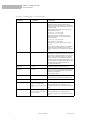
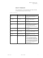
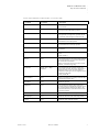
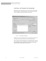
1
S ERIAL C OMMAND S ET
.....
................................ .
This section discusses the DGx serial control commands. The command set
provides access to all of the unit’s functions.
GENERAL
................................................
All DGx functions are accessible by means of serial commands. The command
set is made up of ASCII characters and is not case sensitive.
Typically the device is controlled by a 3rd party machine or by means of an
optional software control program, called the Virtual Control Panel (VCP). This
program allows a user to control the DGx directly from a PC running the
Windows Operating system. See “Control Software For Windows” on page
32" for more information on this program.
SERIAL COMMAND SET USAGE
................................................
The serial command set can be used to control the DGx. For example, to set
input 1 as the channel to record, type in CHREC 1. The serial command set can
also be used to find out the current state for a particular parameter. For example,
to find out the brightness level of input 3, type BRI 3. The DGx will return the
current value (for example Brightness = 123).
The uppercase letters in the command name can be used to abbreviate the
command on the prompt line. For example, CHannelRECord, you can use
CHREC, and for CONTrast, you can use CONT. A space is required between
a command and its argument.
The following tables list all of the commands for controlling the DGx. Note that
some commands will differ based on your recording device—either the DV tape
recorder or the Digital Storage Subsystem (DSS)
350-7277-1-CD
DGx User Manual
1
1
SERIAL COMMAND SET
Input Commands
INPUT COMMANDS
................................................
These commands allow you to make adjustment to your input settings and then
save these settings into the unit’s internal memory.
INPUT COMMANDS
Command
2
Arguments
Description
INput
<input # | ALL>
[AUTO | LOCK | DEBUG]
Sets the input mode for the specified input. Auto
engages the autosync circuitry. Lock disables the
autosync circuitry. Debug provides information on
input status and reports changes to measured
parameters.
INputInteractive
<input #>
Enters input interactive mode to visually adjust
timing parameters of the specified input. A white box
frame and crosshair appear over the full screen input.
Starting with the lower-right corner of the image, use
these keyboard controls to position the image within
the white frame:
I = move up
M = move down
J = move left L = move right
With the lower-right corner properly adjusted,
address the upper-left corner next by using these
keyboard controls:
i = move up
m = move down
j = move left l = move right
With the image properly adjusted, quit the utility:
q = quit
After you have adjusted the input to your satisfaction,
use the Input Name command to name your input
source, and the Input Save command to store the
Input List.
INputLIST
[<1..50>] [<1..50>]
<[ACTIVE]>
Displays the entire Input List of saved input timings.
If arguments are supplied, displays on the portion of
the list requested. The Active argument displays all
saved list entries.
INputLOAD
<input #> <1..50>
Loads the indicated entry from the Input List to the
specified input channel. The entry is loaded only if it
matches the measured parameters of the signal—sync
format and polarity, interlace state, vertical total, and
horizontal frequency.
INputName
<input #> <name>
Assigns a name to the specified input. The argument
can be up to 17 alphanumeric characters with no
spaces (underscore is acceptable).
Factory default: Auto_1
INputSave
<input #> <1..50>
Saves the specified input to the selected entry in the
Input List. These settings are recalled whenever the
signal is reapplied to the DGx.
INputDELete
<1..50>
Deletes the specified input from the Input List.
INputTiming
<input #><hfp> <hs> <hbp>
<hact> <vfp> <vs> <vbp>
<vact>
Sets the timing of the selected input.
Note: The vertical total cannot be changed from the
measured value; that is, the total of <vfp> + <vs> +
<vbp> + <vact> must remain constant.
See Table 7 on page 31 for ranges and factory
defaults.
DGx User Manual
350-7277-1-CD
.....
SERIAL COMMAND SET
Output Commands
INPUT COMMANDS
Command
(CONTINUED)
Arguments
Description
INputTiming
<input #>[hfp | hs | hbp | hact
]<value>
Sets the timing of the selected input. This is an
alternative style of entry that allows single parameter
changes of horizontal timing parameters.
See Table 7 on page 31 for ranges and factory
defaults.
INputTYPE
<input #> <RGB |
COMPOSITE | SVIDEO |
COMPONENT>
This command is used for channels with video input
option boards. The command selects between the four
possible inputs types of such a channel. One input per
channel can be used at a time.
The input argument can only be "1" or "3" since these
are the only input channels which support the
optional video board.
NOTE: After the input type has been changed you
should type SAVECONFIGURATION to save
your changed settings.
Factory default: RGB
INputFormat
<input #>
InputFormat is a read-only command for checking
the video format of the current video input selection.
The command is only valid when Input Type is set to
either Composite, Component, or S-Video. The
response to the command will be NTSC or PAL.
The input argument can only be "1" or "3" since these
are the only input channels which support the
optional video board.
OUTPUT COMMANDS
................................................
These commands control the output of the DGx. You may need to make timing
adjustments to the timing settings to better suit your display device.
OUTPUT COMMANDS
Command
Arguments
Description
ClearHostList
(none)
Clears the Host List of all user-defined hosts.
HOST
(none)
A query command which returns information on the
selected host timing.
350-7277-1-CD
DGx User Manual
3
1
SERIAL COMMAND SET
Output Commands
OUTPUT COMMANDS (CONTINUED)
Command
4
Arguments
Description
HostInteractive
(none)
Enters the host interactive mode. This is an
adjustment mode for changing the Host Timing
values to better suit your display device. Once in the
interactive mode, a white box and crosshair appear on
the output display.
Starting with the lower-right corner of the box, use
these keyboard controls:
I = move up
M = move down
J = move left L = move right
With the lower-right corner properly adjusted,
address the upper-left corner next by using these
keyboard controls:
i = move up
m = move down
j = move left l = move right
With the image properly adjusted, quit the utility:
q = quit
After you have adjusted the input to your satisfaction,
use the Host Name command to name your input
source, and the Host Save command to store the Host
List.
HostLIST
[<1..12>] [<1..12>]
Displays the entries in the Host List. Without
arguments, the command returns the entire list. With
one argument, it returns information on the specified
Host List entry. With both arguments, it returns the
portion of the Host List specified by the arguments.
The first ten entries are user-defined. Entries 11 and
12 are the factory hosts supported by RGB Spectrum.
See Table 6 for a description of the Host List.
Factory default: Host #11
HostLOAD
<1..12>
Loads the indicated host from the Host List.
HostName
<name>
Assigns a name to the current host. The argument can
be up to 17 alphanumeric characters with no spaces
(underscore is acceptable).
Factory default: Auto_1
HostSave
<1..10>
Saves the current host settings into the Host List. The
argument specifies which Host List position is used.
HostDELete
<1..10>
Deletes the specified user-defined host.
HostTiming
<hfp> <hs> <hbp> <hact>
<vfp> <vs> <vbp> <vact>
<hfreq> <sync> <hpol> <vpol>
<il>
Sets the timing for the current host.
Factory default: Host #11, 1280x1024, 75 Hz
See Table 6 on page 31 for a description of the Host
List.
HostTiming
[ hfp | hs | hbp | hact | vfp | vs |
vbp | vact | hfreq | sync | hpol |
vpol | il ] <value>
Sets the timing for the current host.
Factory default: Host #11, 1280x1024, 75 Hz
See Table 6 on page 31 for a description of the Host
List.
DGx User Manual
350-7277-1-CD
.....
SERIAL COMMAND SET
Image Commands
IMAGE COMMANDS
................................................
These commands allow you to make adjustments with the Input Commands,
you can then adjust the image controls for each input.
IMAGE COMMANDS
Command
Arguments
Description
BRIght
<input # | ALL> <-500..500>
Sets brightness value of the selected input. The ALL
argument sets brightness for all four inputs.
Factory default: 0
CHannelINput
<1..4 | QUAD>
Selects an input for display and adjustment (i.e.
timing adjustments, image controls).
Factory default: 1
CONTrast
<input # | ALL> <0..200>
Sets contrast value of the selected input. The ALL
argument sets contrast for all four inputs.
Factory default: 100
GAMma
<input # | ALL> <0.5...2.0>
Sets a unique gamma value for each input when
displayed or played back in full screen. If you play
back in quad mode, gamma will equal 1.0.
The ALL argument sets gamma for all four inputs.
Factory default: 1.0
HUE
<input #> <-180..180>
Sets hue value of the selected input. Hue is only valid
for video option board inputs.
Factory default: 0
SATuration
<input #> <0..200>
Sets saturation value of the selected input. Saturation
is only valid for video option board inputs.
Factory default: 100
SHARPness
<input #> <0 | 1 | 2 | 3>
Sets sharpness value of the selected input.
Factory default: 2
WINdow
<input # | ALL> <ON | OFF>
This command is used to turn on or off one or all
inputs.
If Window is Off and the input to that channel is
removed and reapplied within two seconds, then the
status remains Off. If Window is Off and the input is
removed and reapplied after more than two seconds,
the Window status reverts to On. This allows for the
use of a switcher and maintaining the desired On/Off
status. It also means that when a previously unused
input is used, the Window automatically turns On
allowing the new input to be displayed.
Factory default: ALL ON
350-7277-1-CD
DGx User Manual
5
1
SERIAL COMMAND SET
Tape Recorder Commands
TAPE RECORDER COMMANDS
................................................
These commands are used to control both the DGx and the connected DV tape
recorder.
TAPE RECORDER COMMANDS
Command
6
Arguments
Description
AUDio
<ON | OFF>
The Audio command enables or mutes audio during
playback.
Factory default: ON
CHannelPLAY
< 1..4 | QUAD> [<1..4>]
Selects which channels to play in the Playback mode.
The first argument is the recorded input that will
playback in your primary output. The second
argument is the recorded input that will playback in
your secondary output. If Quad, then the second
argument is not needed because both outputs will
playback a quad display.
Factory default: 1, 1
FullScreen
<1..4> [<1..4>]
In Playback mode, this command allows you to
change your display options on the fly. This
command takes the selected input source(s) and
displays it in full screen. The full screen
configuration you select overrides the previous
ChannelPlay settings.
QuadView
(none)
In Playback mode, this command switches the output
display to a quad configuration. The QuadView
command overrides the previous ChannelPlay
settings to QUAD.
PLAY
(none)
This command switches unit to Playback mode and
plays the channels you previously selected with the
ChannelPlay command.
Note: To switch from Play to any other recorder
function, you must first type Stop.
PAUSE
(none)
In Playback mode, this command pauses the channels
currently being played. Playback resumes when you
send another Pause command or when you send the
Play command.
FastForward
(none)
In Playback mode, this command fast forwards the
recorder until the end of the tape or until the Stop
command is given.
REWind
(none)
In Playback mode, this command rewinds the
recorder until the beginning of the tape or until the
Stop command is given.
RealTimeSeek
<Year : Month : Day : Hour :
Minutes : Seconds>
Places the tape deck at the selected real time
recording time.
STOP
(none)
This command ceases Play, Rewind, FF, Pause, and
Record recorder functions. Stop does not change what
Setup mode you are currently in.
DeleteMARK
<mark number>
This command will delete the given event mark.
DeleteAllMARKs
(none)
This command will delete all event marks after
asking for confirmation.
EditMARK
<mark number> <description>
This command will update the description of the
specified event mark.
DGx User Manual
350-7277-1-CD
.....
SERIAL COMMAND SET
Tape Recorder Commands
TAPE RECORDER COMMANDS (CONTINUED)
Command
Arguments
Description
ListAllMARKs
(none)
This command lists the timecode and description of
all event marks.
ListMARK
<1..100>
This command will display the timecode and
description of the mark number specified.
MARK
[<HH MM SS FF>]
This command will create an event mark at the time
code specified. If no argument is provided, then an
event mark is created using the current time code.
NEXTMARK
(none)
This command sends the recorder to the next event
mark from the current tape position.
PREVMARK
(none)
This command sends the recorder to the previous
event mark from the current tape position.
SeekToMARK
<mark number>
This command will send the recorder to the specified
event mark.
CHannelRECord
<1..4> [<1..4> <1..4> <1..4>]
Selects which channels to record in the Recording
mode.
Factory default: 1
RECord
(none)
This command switches unit to Recording mode and
records the channel(s) you previously selected with
the ChannelRecord command.
Note: To switch from Record to any other recorder
function, you must first type Stop.
RecordMode
<input# | ALL> <HIgh |
STanDard>
This command sets the resolution at which your
inputs will be recorded, either High (1280x1024) or
Standard (720x575). You can select a different
resolution for each input. The ALL argument sets the
resolution for all inputs.
Factory default: HI
RECorderINFO
(none)
Displays recording device currently connected and in
communication with the DGx.
MediumInfo
(none)
Returns the tape info.
OffTapeInfo
(none)
This command will display which channels are
recorded on the tape and what the resolution was for
the recording (High or Standard). In addition, this
command returns the recorded date and time for the
current tape position.
TimeCodeSeek
<HH MM SS FF>
Positions the tape at the timecode specified.
TimeCodeQuery
(none)
Returns the timecode at the current tape position.
VcrState
(none)
Returns the state of the tape recorder.
350-7277-1-CD
DGx User Manual
7
1
SERIAL COMMAND SET
Disk Recorder Commands (DSS)
DISK RECORDER COMMANDS (DSS)
................................................
These commands are used to control both the DGx and the connected DSS.
DIGITAL STORAGE SUBSYSTEM (DSS) COMMANDS
Command
8
Arguments
Description
AUDio
<ON | OFF>
The Audio command enables or mutes audio during
playback.
Factory default: ON
CHannelPLAY
< 1..4 | QUAD> [<1..4>]
Selects which channels to play in the Playback mode.
The first argument is the recorded input that will
playback in your primary output. The second
argument is the recorded input that will playback in
your secondary output. If Quad, then the second
argument is not needed because both outputs will
playback a quad display.
Factory default: 1, 1
FullScreen
<1..4> [<1..4>]
In Playback mode, this command allows you to
change your display options on the fly. This
command takes the selected input source(s) and
displays it in full screen. The full screen
configuration you select overrides the previous
ChannelPlay settings.
QuadView
(none)
In Playback mode, this command switches the output
display to a quad configuration. The QuadView
command overrides the previous ChannelPlay
settings to QUAD.
PLAY
(none)
This command switches unit to Playback mode and
plays the channels you previously selected with the
ChannelPlay command.
Note: To switch from Play to any other recorder
function, you must first type Stop.
PAUSE
(none)
In Playback mode, this command pauses the channels
currently being played. Playback resumes when you
send another Pause command or when you send the
Play command.
STOP
(none)
This command cancels Play, Pause, and Record
recorder functions. Stop does not change what Setup
mode you are currently in.
DeleteMARK
<mark number>
This command will delete the given event mark.
DeleteALLMARKs
(none)
This command will delete all event marks after
asking for confirmation.
EditMARK
<mark number> <description>
This command will update the description of the
specified event mark.
ListAllMARKs
(none)
This command lists the timecode and description of
all event marks.
ListMARK
<1..100>
This command will display the timecode and
description of the mark number specified.
MARK
[<HH MM SS FF>]
This command will create an event mark at the time
code specified. If no argument is provided, then an
event mark is created using the current time code.
DGx User Manual
350-7277-1-CD
.....
SERIAL COMMAND SET
Disk Recorder Commands (DSS)
DIGITAL STORAGE SUBSYSTEM (DSS) COMMANDS (CONTINUED)
Command
Arguments
Description
NEXTMARK
(none)
This command sends the recorder to the next event
mark from the current mark.
PREVMARK
(none)
This command sends the recorder to the previous
event mark from the current mark.
SeekToMARK
<mark number>
This command will send the recorder to the specified
event mark.
CurrentTRACK
[<track #>]
Without an argument, this command displays current
recorded track that the system is set to.
With an argument, the DSS will seek to the beginning
of the designated track number.
ListTRACKS
[<start track> <count>]
Displays a listing of all recorded tracks on the DSS
hard drive. For each track, the real time, elapsed time,
and recording length are listed.
DeleteTRACK
<track #>
Deletes selected recorded track on DSS and any event
marks within that track. Currently, the DSS
reassembles the sequence and time code positioning
of the remaining recorded tracks.
DeleteALLTRACKS
(none)
Deletes ALL recorded tracks and event marks on the
DSS. The user is prompted for a confirmation before
the tracks are deleted.
NextTRACK
(none)
Moves the DGx/DSS system from the currently
selected track to the beginning of the next recorded
track.
PrevTRACK
(none)
Moves the DGx/DSS system from the currently
selected track to the beginning of the previously
recorded track.
OffTapeInfo
(none)
This command will display which channels are
recorded on the disk and what the resolution was for
the recording (High or Standard). In addition, this
command returns the recorded date and time for the
current disk position.
RealTimeClockSet
(none)
Sets (or resets) the internal DGx real time clock. Note
that the DSS clock is synchronized to this DGx clock
so the Real Time used for recording sessions is based
on this setting.
The default format used is military time. When you
send this command, the DGx will prompt you to
provide the following information: Year, Month,
Date, Day of the Week, Hour, and Minute.
RealTimeSeek
<Year : Month : Day : Hour :
Minutes : Seconds>
Places the DSS at the selected real time recording
time.
RECord
(none)
This command switches unit to Recording mode and
records the channel(s) you previously selected with
the ChannelRecord command.
Note: To switch from Record to any other recorder
function, you must first type Stop.
RECorderINFO
(none)
Displays recording device currently connected and in
communication with the DGx.
350-7277-1-CD
DGx User Manual
9
1
SERIAL COMMAND SET
Disk Recorder Commands (DSS)
DIGITAL STORAGE SUBSYSTEM (DSS) COMMANDS (CONTINUED)
Command
10
Arguments
Description
RecordMode
<input# | ALL> <HIgh |
STanDard>
This command sets the resolution at which your
inputs will be recorded, either High (1280x1024) or
Standard (720x575). You can select a different
resolution for each input. The ALL argument sets the
resolution for all inputs.
Factory default: HI
TimeCodeSeek
<HH MM SS FF>
Positions the DSS track at the timecode specified.
TimeCodeQuery
(none)
Returns the timecode at the current disk position.
CurrentTIME
(none)
Displays currently computed time of DGx internal
clock.
DSSCONNection
<DGX | EXT>
DSSCONNection allows you to mount or unmount
the disk volume with the DSS. Issuing DSSCONN
EXT will cause the DSS to unmount the disk volume
allowing an external computer to read and write to the
disk via the 1394 port on the rear of the DSS labeled
"Ext". To remount the drive, issue the command
DSSCONN DGx command. If used without an
argument DSSCONNection will respond with a
message indicating the current connection status
(DGx or Ext).
NOTE: If the "Ext" port is not connected to a
computer it is not possible to unmount the disk.
VcrState
(none)
Returns the state of the disk recorder.
VOLumeINFO
(none)
Displays disk storage parameters: total disk record
time, used disk time, and remaining disk record time
and disk volume name.
VOLumeNAME
<name>
VOLumeNAME can be used to read or write the DSS
disk volume name. The name can be up to 30
characters in length and may include spaces and
punctuation characters. If no name is specified,
VOLumeNAME prints the current name of the disk.
DGx User Manual
350-7277-1-CD
.....
SERIAL COMMAND SET
Miscellaneous Commands
MISCELLANEOUS COMMANDS
................................................
These commands control a variety of general DGx functions.
MISCELLANEOUS COMMANDS
Command
Arguments
Description
AUTOSAVE
<ON | OFF>
The AutoSave feature automatically stores the system
configuration approximately every ten seconds. The
process stores configuration information such as
HostList, InputList, Host settings, and display
parameters. AutoSave allows you to turn the NVRAM
automatic update mode on or off.
Note: The AutoSave feature can cause sluggish
response to some DGx controls. While the Auto Save
feature is useful during setup of the system, it is best
set to Off during live presentations.
Factory default: OFF
FrontPanel
<ON | OFF>
Enables and disables the front panel.
Factory default: ON
Help
[<command>]
Help, without an argument will display the entire
serial command set. Help, with a command as an
argument will display detailed information about that
command.
ID
(none)
Displays the product identification, product name,
firmware version number, date of manufacture, and
serial number.
RestoreFactoryDefaults
(none)
Restores all user settings to their factory default
values.
SAVECONFIGURATION
(none)
Forces an update and explicit save of the system’s
NVRAM. This stores configuration information such
as HostList, InputList, Host settings and display
parameters.
STATus
(none)
Returns the Status of the DGx and its current settings.
TestPattern
<ON | OFF>
This command turns the internal TestPattern (color
bars) on and off.
Factory default: OFF
CurrentTIME
(none)
The DGx has an internal real-time clock. This
command returns the current date and time. See
RealTimeClockSet for information on how to set the
real-time clock.
RealTimeClockSet
(none)
The DGx has an internal real-time clock that needs to
be set by the user. Once you send this command, you
will be prompted to enter the date, year, and time. We
recommend that you set the clock the first time you
use the DGx. The time can be recalled using the
CurrentTime command.
350-7277-1-CD
DGx User Manual
11
1
SERIAL COMMAND SET
Serial Port Commands
MISCELLANEOUS COMMANDS (CONTINUED)
DGXFIRMWAREUPDATE
(none)
This command updates the firmware for the DGx
daughter board. You will also need to update the DGx
main board with the Update Firmware command.
If the baud rate is other than 57,600, the user will be
prompted to change the baud rate of the terminal
emulator and the DGx to 57,600.
When this is complete, the DGxFirmwareUpdate
command must be re-issued and confirmed. The user
is then prompted to restart the DGx.
Once the DGx restarts, the user is prompted to type
the command STARTDGXUPDATE and then
download the file. On the screen, progress dots
appear during the download.
See Appendix D for more information.
UPDATEFIRMWARE
(none)
This command updates the firmware for the DGx
main board. You will also need to update the DGx
board with the DGx Firmware Update command.
If the baud rate is other than 115,200, the user will be
prompted to change the baud rate of the terminal
emulator and the DGx to 115,200.
When this is complete, the Updatefirmware
command must be re-issued and confirmed. The user
is prompted to download the file.
On the screen, progress dots appear during the
download.
See Appendix D for more information.
VERSION
(none)
Version returns firmware, hardware, and bootcode
revision information.
SERIAL PORT COMMANDS
................................................
The commands control baud rate and echo settings for the serial port.
SERIAL PORT COMMANDS
Command
12
Arguments
Description
BAUDrate
<1200 | 2400 | 9600 | 19200 |
38400 | 57600 | 115200>
Sets the serial port baud rate. The value is
automatically saved in NVRAM.
Factory default: 9600
ECHO
<ON | OFF>
Turns the serial echo On/Off. The value is saved in
the NVRAM. The echo is only on commands typed
and sent to the unit.
Note: Echo setting has no effect on responses issued
by the DGx; responses are always visible, regardless
of the echo status.
Factory default: ON
DGx User Manual
350-7277-1-CD
.....
SERIAL COMMAND SET
Serial Port Commands
TABLE 1. H o s t L is t
#
NAME
HFP HS
HBP HACT
1..10
VFP VS
VBP VACT
HFREQ SYNC
HPOLVPOLIL
(user defined hosts)
11 VESA_1280x1024___75 16 144 248
1280
12 720 x 580_________100 19 56
720
69
1
3
3
38
1024
79980
5
1
3
39
580
62500
5
0
1
0
0
0
TABLE 2. D e fin iti ons and R anges f or Timing Par ame t er s
Parameter
350-7277-1-CD
Definition
Range
(default value)
HFP
Horizontal front porch
0 to 640 pixels
(16)
HS
Horizontal sync
16 to 640 pixels
(144)
HBP
Horizontal back porch
0 to 640 pixels
(248)
HACT
Horizontal active
VFP
Vertical front porch
0 to 512 lines
(1)
VS
Vertical sync
2 to 32 lines
(3)
VBP
Vertical back porch
0 to 512 lines
(38)
VACT
Vertical active
HFREQ
Horizontal frequency in Hz
SYNC
Sync format
HPOL
Horizontal sync polarity
1 or 0
(1)
VPOL
Vertical sync polarity
1 or 0
(1)
IL
Interlaced/Noninterlaced
1 or 0
(0)
DGx User Manual
16 to 1280 pixels
(1280)
12 to 1024 lines
(1024)
15 to 90 kHz
(75)
3, 4, or 5 wires
(5)
13
1
SERIAL COMMAND SET
Control Software For Windows
CONTROL SOFTWARE FOR WINDOWS
................................................
RGB Spectrum offers an optional software control program which runs under
Microsoft Windows 95/98/2000/ME/XP/NT. The DGx Virtual Control Panel
(VCP) is a graphical user interface for RS-232 serial control.
FIGURE 1.
VCP Software for the DGx
With the VCP, you have push button control over all functions of the DGx. The
VCP requires the same serial connections as described in Appendix B.
The VCP comes with an online help feature, so the application is not covered in
this User Manual. If you have purchased the VCP control software, please refer
to the online help, accessible on each section of the software via the “Help”
button located in the bottom right corner of the screen.
14
DGx User Manual
350-7277-1-CD


![Press the [FUNCTION] button.](http://vs1.manualzilla.com/store/data/005738170_1-cd4fded3b03c9e88548afe52897345e1-150x150.png)