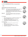
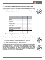
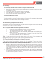
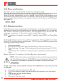
1
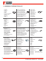
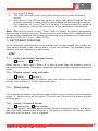
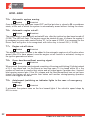
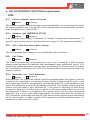
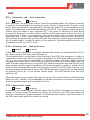
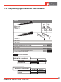
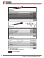
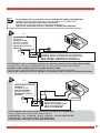
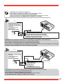
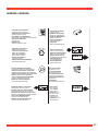
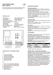
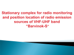
G100 - G300 ISTRUZIONI COMPLETE COMPLETE INSTRUCTIONS 1 - LEGENDA E CONTENUTO DEL KIT. Sirena non autoalimentata Siren without backup battery Sirène non autoalimentée Sirena no autoalimentada Sirene não auto-alimentada Ìç áõôïôñïöïäïôïýìåíç óåéñÞíá Siréna bez vlastního napájení Ej självförsörjande sirén Sirene uten selvmatingsbatteri Sirene uden batteri Radiocomando Radio controls Radiocommande Radiomando Comando por rádio Ôçëå÷åéñéóìüò Rádiové ovládání Fjärrkontroller Fjernkontroller Fjernbetjeninger Cablaggio Wiring harness Câblage Cableado Conjunto de fios Êáëùäßùóç Kabelá Kablar Ledningsnett Kabler Pannello di controllo Control panel Tableau de commande Panel de control Painel de controlo Ðßíáêáò åëÝã÷ïõ Ovládací panel Kontrollpanel Kontrollpanel Styrepanel Cablaggio sirena Siren wiring harness Câblage sirène Cableado de sirena Conjunto de fios da sirene Êáëùäßùóç óåéñÞíáò Kabelá sirény Sirénkablar Ledningsnett sirene Sirenekabler Sacchetto accessori Fittings bag Sachet des accessoires Bolsa de accesorios Saco de acessórios Óáêßäéï ìå áîåóïõÜñ Sáèek p isluenstvím Tillbehörspåse Pakke med monteringsdeler Pose med tilbehør Manuale utente/installatore User/installation manual Manuel utilisateur/Installateur Manual del usuario/instalador Manual de uso/instalação Åã÷åéñßäéï ÷ñÞóôç Návod pro uivatele/instalatéra Användar-/installattionshandbok Brukermanual/installatørmanual Bruger-/installatørmanual Dima di foratura Drilling mask Gabarit de perçage Escantillón para perforar Escantilhão para perfuração Åëáóìá ôñõðÞìáôïò Vrtací ablona Borrningsmall Hullmal Hulskabelon Sensori ultrasuoni Sensor transducers Capteurs à ultrasons Sensores a ultrasonido Detectores de ultra-sons ÁéóèçôÞñáò õðåñÞ÷ùí Ultrazvukové snímaèe Ultraljudssensorer Ultralydsensorer Ultralydsfølere Pin Code Card Pin Code Card Carte Code PIN Tarjeta de código PIN Cartão do código PIN Pin code card Karta s pin kódem Pin code card PIN-kodekort Pin-kode card Staffa Bracket Patte de fixation Estribo Presilha Âñá÷ßïíáò Tømen Bygel Bøjle Bøjle Sirena autoalimentata Siren with backup battery Sirène autoalimentée Sirena autoalimentada Sirene auto-alimentada Áõôïôñïöïäïôïýìåíç óåéñÞíá Siréna s nezávislým napájením Självförsörjande sirén Sirene med selvmatingsbatteri Sirene med batteri Vetrofania Warning sticker Vitrauphanie Calcomanía de advertencia Aviso autocolante Áõôïêüëëçôá ãéá ôá ôæÜìéá Fólie na sklo s upozornìními Varningsetikett Advarselssticker Advarselsmærkat w.c ww obr a-a t.co m Centralina Central unit Centrale Centralita Central Çëåêôñïíéêüò åãêÝöáëïò Centrální jednotka Styrenhet Sentralenhet Central 8772 Driver card Driver card Carte de circuit de commande Driver card Cartão do condutor Driver card Codice ricambio Driver card Spare part code: 4T2771B2G Driver card Driver card Driver card 2 ISTRUZIONI COMPLETE G100-G300 CO EN NT O UT IT S NT O TC KI LK DE E NT om t.c a-a br co w. ww AKG 368 AKG 198 AKG 193 AKG 363 ACG 196 ACG 366 3 3 3 3 3 3 3 3 3 3 3 3 3 3 3 3 3 3 3 3 3 3 3 3 3 3 3 3 3 3 3 3 3 3 3 3 3 3 3 3 3 3 3 3 3 3 3 3 3 3 3 3 3 3 3 3 3 3 3 3 3 3 3 3 3 ISTRUZIONI COMPLETE G100-G300 GB Dear Customer, Thank you and congratulations for choosing our product. It is a technologically advanced alarm system which meets the performance standards set by automobile manufacturers and complies with the European directives. After the system was installed, dear Customer, you were given the radio controls or Driver Card (where foreseen) and the user’s manual, which also contains the product’s declaration of conformity and the relative installation certificate. The manual is divided into 22 parts: Page 2/3 _______ 41 ______ 42 ______ 43 ______ 44/45 ______ da 46 a 50 ______ 51/52 da 52 a 55 56/57 57 ______ ______ ______ ______ 58/59 ______ 60 _______ da 61 a 66 ______ 67/68 ______ 68/69 ______ 70 71 72/73 74 da 75 a 98 ______ ______ ______ ______ ______ LEGENDA AND KIT CONTENTS. INFORMATION. INTRODUCTION. ADDITIONAL PROTECTIONS. LIST OF FUNCTIONS. LIST OF STANDARD FUNCTION (G300) AND SELF-LEARNING PROCEDURE. LIST OF BASIC PROGRAMMABLE FUNCTIONS. LIST OF ADVANCED FUNCTIONS (programmable). SYSTEM COMPONENTS. VEHICLE SPEED SENSOR CONNECTION -VSS (G100-G300). AUXILIARY OUTPUT AUX2. PROGRAMMING. RADIO CONTROL FUNCTIONS CHECK. PROGRAMMABLE FUNCTIONS (G100 -G300). HOW TO PROGRAMME THE (G100 - G300) SYSTEM. PROCEDURE FOR ADDING NEW RADIOCONTROL DEVICES (G100) AND NEW DRIVER CARDS (G300). SWITCHING ON / SWITCHING OFF OF DRIVER CARD. ALARM MEMORY. EMERGENCIES, PERSONALIZING THE PIN CODE. MAINTENANCE TROUBLESHOOTING. SYSTEM TECHNICAL CHARACTERISTICS. DIAGRAMS AND GUARANTEE. Please read the manual carefully to get the full benefit of the product purchased.We also advise you to keep this manual in the same place as your car documents for easy consultation when needed.If any problem arises that cannot be resolved, please contact your dealer. 40 COMPLETE INSTRUCTIONS G100-G300 2 - INFORMATION. The system is equipped with a self-learning function which makes it possible to simplify all operations necessary for adding or replacing radio controls / Driver Cards but only with the user’s consent. For the procedure make reference to the manual at page 69 on www.cobra-at.com 2.1 - Personal PIN CODE. Each G100 - G300 system has a PIN code that is used to disarm the system in emergencies. www.cobra-at.com This is a PIN CODE CARD sample (PIN CODE is a factory-setted): STICK ON PIN CODE LABEL 5CGXXXAIA S/N 0003 050524 PERSONAL PIN CODE PIN CODE 1122 We advise you to stick the PIN CODE adhesive label onto the PIN CODE card (which may be found on the rear of the control unit). COMPLETE INSTRUCTIONS G100-G300 41 3 - INTRODUCTION. These anti-intruder alarm systems are controlled by a radio control device - G100 or G300 - with Driver Card with high security codes. This technology provides an extremely high degree of protection against any attempt to reproduce the code. The radio control makes it possible to activate the system from a distance of 5 - 10 metres from the vehicle, while the drivers card transmits from a distance of 1 - 5 metres from the vehicle. In some circumstances the range may be shorter due to interference from other sources (e.g. radio transmitters operating on the same band). If the radio control is not effective in the usual range, get as close to the vehicle as you can. If radio - controlled window closing is foreseen, we advise you to stay very close to the vehicle when carrying out this operation to make sure it is performed under safe conditions. Your vehicle’s complete protection is assured by: Mod. AKG 368 AKG 198 AKG 193 AKG 363 ACG 196 ACG 366 ENGINE LOCK PROTECTION VOLUMETRIC PROTECTION PERIMETRIC PROTECTION WIRING CUT PROTECTION Note: in product G366 (without us) the perimeter connection must only be made on the door pushbutton connection. 42 COMPLETE INSTRUCTIONS G100-G300 4 - ADDITONAL PROTECTIONS (G100-G300). You can increase the protection level of the system with the following additional sensors: 5452: Level monitor module. When the system is armed, this sensor will detect the vehicle being jacked up to tow it away or steal the wheels. 5462: Hyperfrequency module. When the system is armed, hyperfrequency emissions from the module hidden in the car will ensure volumetric protection of the vehicle. 2980: Windows lift module. The electric windows of your car will raise automatically when the system is armed. COMPLETE INSTRUCTIONS G100-G300 43 5 - LIST OF FUNCTIONS. 5.1 - Standard functions list. The following list indicates the main functional characteristics of the alarm system. G100 • • • • Radiocontrol button functions. Arm / Disarm by means of dynamic - code radio controls. Disablement of the sensor transducer and / or external sensor. Panic alarm. G300 • • • • • Arm / disarm controls self - learning procedure. Arm by means of the vehicle’s original radio controls Driver card armed / disarmed. Disablement of the sensor transducer and / or external sensor. Driver card functions. G100 - G300 • Volumetric protection of the vehicle’s interior by ultrasonic sensor not requiring sensitivity adjustment. • Perimetric protection. When the alarm is armed, after 25 s the siren will sound if a door or the bonnet or boot is opened. • Protection of start attempts. With the alarm connected the engine is blocked and a start attempt generates an alarm. • When an alarm occurs the siren sounds for 30 s. The direction lamps flash. • Emergency disarming by pin-code. • Wire-cutting protection. • Original centralised door and boot closing system. • LED indicating the system’s status with alarm-record memory function. • Safety circuit to prevent the system being armed when the engine is running. • Coupling of modules / siren 4310 / satellite alarm ICD31 on Cobra Bus line. 5.2 - List of basic functions (programmable). These are the functions that require programming in keeping with the vehicle model and desired operating characteristics of the alarm system. Please refer to the basic functions table in the programming tables section. G100 • • • • Centralised closing times. Controlled comfort window closing. Silent arming. Armed/disarmed blinker 44 COMPLETE INSTRUCTIONS G100-G300 G100 - G300 • .• • • Door / bonnet / boot open signal. Automaticsystem arming. Automatic start prevention arming (starter). Start prevention alarm. 5.3 - List of advanced functions (programmable). These are special functions that require programming in keeping with the desired operating characteristics of the alarm system. Please refer to the advanced functions table in the programming tables section. G100 • • • • • • •· • . Autolock - Automatic door locking. Autolock - AMERICAN STYLE. AutoHazard (switching on indicator lights in the case of emergency braking). Door closing by anti-diversion alarm. Car Finder. Automatic anti - theft protection. Voluntary anti - theft protection. Trunk Release (truck opening). G300 • Automatic anti - theft protection. •· Voluntary anti - theft protection. G100 - G300 • • • • • • Automatic anti - theft protection delay with odometer. Pager output. Anti - diversion blocker. Anti - diversion alarm. Buzzer. Speed limit signal. COMPLETE INSTRUCTIONS G100-G300 45 6 - LIST OF STANDARD FUNCTIONS (not programmable). G100 RADIOCONTROL BUTTON FUNCTIONS (G100). Button A Button B This button arms the alarm and blocker system, deactivates the volumentric input and additional sensors input, activates the panic option, gives access to the programming function, selects the line and raises the buzzer volume in the programming table, and activates the Car Finder option. B B A A This button deactivates the alarm, block system, activates/deactivates the function and lowers the buzzer volume. 6.1 - Arming. • • • • • B When radiocontrol button “A” is pressed, the doors lock (if the vehicle is equipped with a centralized locking system). The direction lights flash twice. The buzzer emits two acoustic signals (if enabled). The protection functions activate after 25 s. The LED lights up and stays on for 25 s, then flashes. A 6.2 - Disarming. • • • • • When radiocontrol button “B” is pressed, the doors unlock. The direction lights flash once. The buzzer emits one acoustic signal (if enabled). The protection functions are immediately deactivated. The LED is switched off. B A 46 COMPLETE INSTRUCTIONS G100-G300 6.3 - Interrupting an alarm during the warning-signal cycle. While the system is sounding the alarm it is possible to deactive the siren and flashing lights by pressing radio control button “B” once (one press). This operation interrupts the alarm cycle, but the system stays armed. To deactivate the system completely, it is necessary to disarm it by pressing radiocontrol button “B” again (two presses). RADIOCONTROL FUNCTIONS Arming Button A B A Button B Disarming Interrupt alarm Panic alarm Deactivate ultrasonic volumetric sensor and additional sensor (if installed) Car finder 6.4 - Deactivating the ultrasonic volumetric sensor. If you wish to activate the protection system with the windows left open or when a passenger will be staying inside the passenger compartment, it is possible to deactivate the volumetric sensor so that it will not generate any alarms. 1) Activate the system by pressing radiocontrol button “A”. 2) Press radiocontrol button “A” again within 25 s. If a hyperfrequency or anti-lifting sensor is installed, it is possible to disable it by pressing button “A” twice within 25 s. The reception of the signal is confirmed by one flash of the direction indicators and by an acoustic signal from the buzzer (if enabled). The sensor has been disabled; all the other protection functions remain active. The sensors will be automatically reactivated the next time the system is armed COMPLETE INSTRUCTIONS G100-G300 B B A A 47 6.5 - Panic Alarm. Whenever you press radiocontrol button “A”, provided 25 s have elapsed after arming the system, it will produce an alarm cycle (siren sound and flashing direction lamps). If the Car Finder function is enabled, press radiocontrol button “A” twice (2 consecutive presses). To stop the panic alarm, press radiocontrol button “B. G300 INTRODUCTION. This alarm system can self-learn a series of recurrent signals that take place on the vehicle when the operations for locking and unlocking the doors are executed the original radio control device. The signals that are normally utilised are the engine comand, door deflector status and direction indicator signals. If connection to the direction indicators is foreseen for alarm activation/deactivation, please note that: • the alarm may not activate / deactive when the vehicle’s emergency blinker is on. 6.6 - Arm / disarm controls self - learning procedure. For self-learning of the arm / disarm commands through the vehicle’s original radiocontrol device, the following conditions are indispensable: 1) G300 system disarmed. 2) Door and bonnet closed. 3) Ignition off (+15 absent). Proceed as described: A) Connect the GREY - BLACK lead to Ground (GND) for at least 1 s. B) The LED will start to flash slowly. C) Press the Lock (close) button on the vehicle’s original radiocontrol. D) The LED flashes fast while awaiting the door opening signal. E) Press the Unlock (open) button on the vehicle’s original radiocontrol device for the system disarmed signal. F) The confirmations of the happened self-learning process of the signal is confirmed by an acoustic signal emitted by the buzzer. 48 COMPLETE INSTRUCTIONS G100-G300 6.7 - Arming 6.7.1 Arm by means of the vehicle’s original radio controls • • • • When the lock button on the original radiocontrol is pressed, the doors lock and the system is armed. The buzzer emits two acoustic signals (if enabled). The LED lights up and stays on for 25 s, then flashes. The protection functions activate after 25 s. 6.7.2 Arm with Driver Card It is also possible to connect the alarm system in the event of an emergency by pressing the button on the Driver Card, without locking the doors. 6.8 - Disarming (using the Driver Card). Introduction: the alarm is disconnected using the vehicle’s original remote control and by recognition of the Driver Card as follows: 6.8.1 - original radiocontrol recognition procedure. • • • • Press the original radiocontrol button to unlock the doors. The direction lights flash (“pre - disarm” phase). The protection functions are temporarily deactivated while awaiting the Driver Card signal. The buzzer emits an acoustic signal (if enabled). Once the Driver Card has been recognised, the LED switches off. Note: it is also possible to disarm the alarm system in the event of an emergency by pressing the button on the Driver Card, without unlocking the doors. 6.9 - Deactivating the ultrasonic volumentric sensor. If you wish to arm the protection system with the windows lift open or when a passenger will be staying inside the passenger compartment, it is possible to deactivate the volumetric sensor so that it will not generate any alarms. • • Within 5 s after having turned off the ignition and from the door opening, keep the button pressed down until you see the LED give a long flash. If a hyperfrequency or anti-lifting sensor is installed, it is possible to disarm it by pressing the button again within 5 s after the LED has flashed. The LED will flash again to confirm its deactivation. Arm the system by pressing the radiocontrol button: the sensors are deactivated but all the other protections are active. The sensors will be automatically reactivated the next time the ignition is turned on. COMPLETE INSTRUCTIONS G100-G300 49 6.10 - Driver card Function. The Driver Card is used exclusively for the user recognition phase: When the doors are unlocked by the vehicle’s original radiocontrol the system goes into a “pre-disarm” phase which lasts for 25 s, activated by the opening of a door. When 25 s have elapsed after the door opened, unless Driver Card recognition has occurred an alarm state is generated. It is possible to disarm the system during the alarm phase using the Driver Card key or by keying in the entire Pin Code from the LED panel (see page 72). G100 - G300 6.11 - Protection functions. When the system is armed, opening the bonnet/boot/door or attempting to start the vehicle generates an acoustic and visual alarm cycle that lasts approximately 30 s. In products that include a volumetric sensor, the alarm will be triggered off by intrusion into the passenger compartment. At the cycle’s end the system stays armed. 6.12 - Coupling of modules / siren 4310 / satellite alarm ICD31 on Cobra Bus line. On the Cobra Bus line (pin 14) it is possible to connect the following additional modules (Siren 4310 / anti-lifting module / satellite alarm ICD 31 / Engine lock 8509) by means of the following programming procedure: 1. 2. 3. 4. Disconnect system. Enter programming mode using the dedicated procedure for the product. Move from page 1 to page 7 by activating and de-activating the panel (+15 ON / OFF). The storage and completion of programming is signalled by flashing indicator lights. Repeat from point 1 if a module of the Cobra Bus line is disconnected. NOTE: with the alarm disconnected, disconnecting a self learning module from the Cobra Bus line, when the G100/G300 is armed the indicator lights will flash 8 times and if the Buzzer is activated it will signal 8 times by the buzzer. ATTENTION! If both radiocontrol devices (G100) or Driver Card (G300) have been lost, proceed as follows: A. B. C. D. E. Disarm the system by keying in the PIN code. Cut off the system’s power feed (disconnnect the connector from the central unit). Open a door and the vehicle’s bonnet. Turn on the ignition. Reconnect the power feed. 50 COMPLETE INSTRUCTIONS G100-G300 F. G. H. I. Key in the PIN code. The LED will confirm with a long flash that the code you have entered is correct. After about 5 s the LED will light up with a steady light and by 5 flashes from the direction indicators to signal that you have entered the self-learning procedure. Ref. subsection 16.1 point 7 and 16.2 the point 8 of the procedure for adding on new radiocontrol / Driver Card devices for all the transmitters to be enabled. Note: When a new remote control / Driver Card is coupled, the system automatically prevents use of the previous ones. They can only be used if they are re - enabled through the self-learning procedure.The system can memorize up to a maximum of 4 radiocontrol devices (G100), or 4 Driver Cards (G300). 7 - LIST OF BASIC FUNCTIONS As the functional characteristics of this system can be personalised, the installer will have clearly marked in this manual which of them are enabled. The standard factory setting is the one indicated by a dark square. G100 7.1 • Controlled comfort window closing. Enabled Disabled When arming, if radio control button “A” is kept pressed down the windows close in controlled comfort mode. This makes it possible to stop the window rising by releasing the button. 7.2 • Window control delay activation. Enabled Disabled If radiocontrol window output is enabled, when this function is activated the windows will rise with a delay of 1 s after closing the doors. 7.3 • Silent arming. For temporary elimination of the buzzer signal when arming the system, press radiocontrol button “A” before turning off the ignition. The next time it is armed, the buzzer will start working again. 7.4 • Armed / Disarmed blinker. Enabled (G100) Disabled (G300) The system signals it has been armed with two blinks of the direction lamps, and signals that it has been disarmed with one blink. If this function is disabled, the direction lamps blink only when an alarm cycle is triggered. COMPLETE INSTRUCTIONS G100-G300 51 G100 - G300 7.5 • Automatic system arming. Enabled Disabled Once the ignition key has been turned OFF and the last door is closed a 20 s countdown starts, at the end of which the system is automatically armed without locking the doors. 7.6• Automatic engine cut-off . Enabled Disabled The engine block is automatically activated 2 min. after the ignition key has been turned off (G100). The LED will flash. The engine cannot be started up now; to disarm the system it is necessary to press radio control button “B”. In the case of G300, it is necessary for the Driver Card and ignition to be recognised, with inition key is turned ON. (+15 ON) 7.7 • Engine cut-off alarm. Enabled Disabled This allows the alarm function to be added to the automatic engine cut-off function when armed. After 20 s have passed, once the engine cut-off function is activated, turning on the ignition generates an alarm. 7.8 • Open door/bonnet/boot warning signal. Enabled Disabled When armed, the system emits signals consisting of buzzing and blinking (5 blinks instead of 2) if any doors and / or the bonnet or boot are open. If it is closed within 25 s, the system will continue to monitor their status and will signal again if another door / bonnet/ boot opening occurs later. If the 25 s elapse and the door/bonnet/boot has not yet been closed, the system will not monitor their status until another closing/opening operation occurs that triggers an alarm. 7.9 • Autohazard (switching on indicator lights in the case of emergency braking). Enabled Disabled If activated, the system turns on the four hazard lights if the vehicle’s speed drops by 50% in one s. 52 COMPLETE INSTRUCTIONS G100-G300 8 - LIST OF ADVANCED FUNCTIONS (programmable). G100 8.1 • Select automatic door lock mode. Enabled Disabled This makes it possible to have the doors close automatically at a pre-set speed or within 20 s after the ignition key is turned ON. In this case the doors are automatically unlocked when the ignition key is turned OFF. 8.2 • Autodoor lock (AMERICAN STYLE). Enabled Disabled If the American Style closing is activated, ref. Section “Programming closing times”. To correctly carry out the function, activate also line 4 page 2 in the programming tables. 8.3 • Anti - diversion allarm door closing. Enabled Disabled This function adds door-closing to the anti-diversion alarm procedure. 8.4 • Car Finder. Enabled Disabled This function will allow you to find where your car is, e.g. in a parking lot. With the alarm system armed and once the inhibition time has elapsed, when radiocontrol button “A” is pressed the system generates a visual alarm by activating the blinkers (and the buzzer too, if enabled) for a maximum of 10 s.The Car Finder function can be used only when the system is armed. 8.5 • Automatic anti - theft protection. Enabled Disabled With this mode, the user of the vehicle must be recognised before the vehicle is started. In order to be recognised it is necessary to enter the first 2 digits of the Pin code, or the Driver Card signal must be recognised (if self-learned); within 25 s from switching on the panel. The recognition is confirmed by flashing of the LED. This enables normal use of the vehicle until the panel is next switched off. If the panel is switched off after being recognised, there are 7 s within which to switch on the panel again without the need to be recognised. If there is no recognition, the remote controls are no longer recognised and after 4 min. a 4 min. cyclic alarm is generated. The alarm stops when you turn at the OFF position the ignition key and after 25 s the alarm system and the engine immobiliser will be armed again. In order to switch off the system in the theft protection mode, it is necessary to enter the full Pin Code. COMPLETE INSTRUCTIONS G100-G300 53 8.6 • Voluntary anti - theft protection. Enabled Disabled In this mode the vehicle user voluntarily activates the function by pressing button “B” on the remote control with the panel switched on. The activated status is confirmed by fast flashing of the LED. After activation, if a door is opened the remote controls are no longer recognised, the LED stops flashing and after 4 min. a 4 min. cyclic alarm is generated; to avoid this situation, the alarm sistem must be recognised the driver card (if self-learned), or must be entred the frist two digits of the Pin code.The alarm stops when you turn at the OFF position the ignition key and after 25 s the alarm system and the engine immobiliser will be armed again. In order to switch off the system in the theft protection mode, it is necessary to enter the full Pin Code. If a door must be opened when the function is active (the LED flashes fast), it must firstly be deactivated by pressing button “B” on the remote control again. The LED flashes once and then switches off. When the system goes in alarm, the siren will play for 30 s and the direction indicators will flash for 4 min.; instead, if the loudspeaker or the horn have been connected, a visual and acoustic signalling alarm will be emitted for 4 min. 8.7 • Speed limit signal. Enabled Disabled If activated, the system signals that the speed limit has been exceeded by means of a buzzer. In order to store the speed limit, press button “A” on the remote control when the vehicle is travelling at the desired speed. To deactivate the function, press button “A” on the remote control once whilst the vehicle is moving. 8.8 • Trunk Release (truck opening) Enabled Disabled If the Trunk Release function is activated, with the pressure of both radio control keys to “A” and “B” one has the trunk opening. This is signalled by a 4 s flashing of the indicator lights, and the automatic exclusion of the internal and door ultrasound devices, and the additional modules, too, if they are connected. When the trunk is closed the system automatically reactivates. 54 COMPLETE INSTRUCTIONS G100-G300 G300 8.9 • Automatic anti - theft protection. Enabled Disabled With this mode, the user of the vehicle must be recognised before the vehicle is started. In order to be recognised it is necessary to enter the first 2 digits of the Pin code, or the Driver Card signal must be recognised (if self-learned); within 25 s from switching on the panel. The recognition is confirmed by flashing of the LED. This enables normal use of the vehicle until the panel is next switched off. If the panel is switched off after being recognised, there are 7 s within which to switch on the panel again without the need to be recognised. If there is no recognition, the remote controls are no longer recognised and after 4 min. a 4 min. cyclic alarm is generated. The alarm stops when you turn at the OFF position the ignition key and after 25 s the alarm system and the engine immobiliser will be armed again. In order to switch off the system in the theft protection mode, it is necessary to enter the full Pin Code. 8.10 • Voluntary anti - theft protection. Enabled Disabled In this mode the vehicle user voluntarily activates the function by pressing button “B” on the remote control with the panel switched on. The activated status is confirmed by fast flashing of the LED. After activation, if a door is opened the remote controls are no longer recognised, the LED stops flashing and after 4 min. a 4 min. cyclic alarm is generated; to avoid this situation, the alarm sistem must be recognised the driver card (if self-learned), or must be entred the frist two digits of the Pin code.The alarm stops when you turn at the OFF position the ignition key and after 25 s the alarm system and the engine immobiliser will be armed again. In order to switch off the system in the theft protection mode, it is necessary to enter the full Pin Code. If a door must be opened when the function is active (the LED flashes fast), it must firstly be deactivated by pressing button “B” on the remote control again. The LED flashes once and then switches off. When the system goes in alarm, the siren will play for 30 s and the direction indicators will flash for 4 min.; instead, if the loudspeaker or the horn have been connected, a visual and acoustic signalling alarm will be emitted for 4 min. 8.11 • Speed limit signal. Enabled Disabled If activated, the system signals that the speed limit has been exceeded by means of a buzzer. In order to store the speed limit, press the button on the LED panel when the vehicle is travelling at the desired speed. To deactivate the function, press the button on the LED panel once whilst the vehicle is moving. COMPLETE INSTRUCTIONS G100-G300 55 G100 - G300 8.12 • Automatic anti - theft protection delay with odometer. Enabled Disabled If the theft protection function is controlled by a movement sensor (page 5 line 6 active in the programming tables for the G300; page 4 line 6 active in the programming tables for the G100), at a speed other than 0, there is a delay of 4 min.; if the vehicle stops this calculation is suspended. A cyclic sequence of alarms is generated after 4 min. which last 4 min.. Enter the full Pin Code at this point to be recognised. 8.13 • Pager. Enabled Disabled Negative command to control a Pager module. 8.14 • Anti-diversion block. Enabled Disabled After the system has been disarmed by radiocontrol, if the ignition key is not turned on within 40 s the block is automatically rearmed. 8.15 • Anti-diversion alarm. Enabled Disabled After the system has been disarmed by radiocontrol, if the ignition is not turned on within 40 s the system is automatically rearmed. If a door or the boot are opened, the count down is cancelled. 8.16 • Buzzer. Enabled Disabled The buzzer emits acoustic signals synchronized with the blinking of the direction lamps when the system is armed/disarmed. 56 COMPLETE INSTRUCTIONS G100-G300 9 - POSITIONING THE SYSTEM’S COMPONENTS. All system components must be positioned in places that are not readily accessible and are not close to sources of heat. 9.1 - Alarm Central Unit. To be fixed in place inside the passenger compartment using the bi-adhesive provided in the kit, making sure that the main connector faces downwards. O.K. 9.2 - Siren with backup battery. To be fixed in place inside the engine compartment, making sure that it is positioned so as to face in the direction indicated. NO 1 Ø 3 mm. 9.3 - Siren without backup battery. To be fixed in place inside the engine compartment, making sure it is fastened with the screws provided for this purpose to a metal surface that allows the heat from the magnet to disperse. 4 2 3 9.4 - Ultrasonic volumetric sensor (if foreseen G100G300). The sensor heads can be installed on the upper part of the front windshield or back window side-columns, making sure that they are not covered when the sun-shield flaps are lowered. Check that the heads are correctly oriented when you perform the functional test on the system. The type of sensor used in this alarm system does not require any adjustment. It is suitable for vehicles of all types regardless of the dimensions of their COMPLETE INSTRUCTIONS G100-G300 57 passenger compartment. 9.5 - Bonnet button (G100 - G300). The installation of this button is indispensable to allow access to the alarm programming and radiocontrol self - learning procedures. When installation is completed, check that the button is pressed by the bonnet to the extent of at least 5 mm. Check that the button does not press on the sound-absorbing panels or the outer bodywork plate-metal, as these materials could beome dented with the passing of time. 9.6 - Antenna (G100 - G300). The correct positioning of the antenna is essential for the proper operation of the radiocontrol/Driver Card system. The cable must not be cut, rolled up, or connected to another cable or to the bodywork and must be kept separate from the wiring harness. Position the antenna so that it is at least 20 mm away from metal parts. 9.7 - Emergency Panel. To be installed on the dashboard in a position that also ensures that the button can be reached and the LED can be seen by the user, as in addition to its deterrent function the panel (LED + button) is used during programming operations and in the user recognition. 10 - VEHICLE SPEED SENSOR CONNECTION - VSS (G100 - G300). The VSS signal frequency is proportional to the speed of the vehicle (it is normally a rectangular signal with f max = 4 KHz). If the activated function requires it, the VSS signal must be connected to the PINK - BLACK wire of the alarm. In some vehicles, the signal must be taken straight from the combined instrument. The signal must not be taken from the ABS control system or from control circuits as this could impair the vehicle’s safety and the way it operates. 11 - AUXILIARY OUTPUT AUX2. It is the dedicated output for the “Pager” module connection and for the followings functions: • Pager. • Trunk Release. • Windows lift closing. • Automatic doors looking (AMERICAN STYLE). 58 COMPLETE INSTRUCTIONS G100-G300 G300 HOW TO START PROGRAMMING ALARM SYSTEM DISARMING A OFF O FF C E F ON ON D B IGN +15 OK HOW TO CHANGE TABLE OFF O FF HOW TO GO OUT ON ON HOW TO CHANGE LINE HOW TO ACTIVATE/DEACTIVATE A FUNCTION 60 COMPLETE INSTRUCTIONS G100-G300 14.2 - Programming pages available for the G300 version. G300 BUZZE R TAB LE Vol + Vol - BUZZER VOLUME PAGE 2 MAX. 1s ABLE IONS T FUNCT BASIC Lon g Fla Sho shin g MIN. 2s rt Fla shin g PAGE 3 1 NOT USED 2 NOT USED 3 NOT USED 4 DEFINES PERIMETRIC CONNECTION Ý ENABLE DISABLE 5 NOT USED 6 DOORS BUTTON POLARITY # ENABLE DISABLE 7 PULL UP FOR READING NEGATIVE INPUT ENABLE DISABLE 8 LONG BLINKING AFTER SIREN ENABLE DISABLE FACTORY PROGRAMMING Ý PERIMETRIC CONNECTION SELECT 1 DOOR BUTTON # DOORS BUTTON POLARITY SELECT 2 DISABLE ROOF LIGHT ENABLE SELECT 1 SELECT 2 NEGATIVE ENABLE DISABLE POSITIVE ENABLE DISABLE COMPLETE INSTRUCTIONS G100-G300 65 ABLE IONS T FUNCT BASIC PAGE 4 1 AUTOMATIC SYSTEM ARMING ENABLE DISABLE 2 AUTOMATIC ENGINE CUT-OFF ENABLE DISABLE 3 ENGINE CUT-OFF ALARM ENABLE DISABLE 4 ANTI-DIVERSION BLOCK ENABLE DISABLE 5 ANTI- DIVERSION ALARM ENABLE DISABLE 6 NOT USED 7 OPEN DOOR SIGNALLING AT ARMING ENABLE DISABLE 8 BLINKER SIGNALLING IN ARMING AND DISARMING PHASES E S TABL NCTION CED FU ADVAN Lon DISABLE Sho g Fla rt Fla shin g shin g PAGE 5 1 BUZZER ENABLE/ DISABLE ENABLE DISABLE 2 NOT USED ENABLE DISABLE 3 NUMBER OF ALARM CYCLES ENABLE DISABLE 4 AUTOMATIC ANTI-ROBBERY ENABLE DISABLE 5 MANUAL ANTI-ROBBERY 6 NOT USED ENABLE DISABLE 7 AUTOHAZARD ENABLE DISABLE 8 EXCESSIVE SPEED SIGNALLING ENABLE DISABLE ENABLE DISABLE ENABLE DISABLE ENABLE DISABLE ENABLE DISABLE ENABLE DISABLE 7 WINDOWS OUTPUT ON AUX2 ENABLE DISABLE 8 WINDOWS OUTPUT DELAY ENABLE DISABLE PAGE 6 1 COBRA BUS PRESENCE DISABLE = FIXED ENABLE = ALTERNATE 2 HORN: DISABLE= LOUDSPEAKER 3 SIREN OUTPUT TYPE: ENABLE=HORN 4 PAGER è 5 TIME ALARM ENABLED 6 NOT USED èEnabled : PAGER COMMAND = ALARM TIME 30". FACTORY PROGRAMMING 66 COMPLETE INSTRUCTIONS G100-G300 E S TABL NCTION CED FU ADVAN Lon Sho g Fla rt Fla shin g shin g PAGE 7 1 COBRA BUS SIREN ENABLE DISABLE 2 EXTERNAL MODULE VIA COBRA BUS ENABLE DISABLE 3 ENGINE CUT-OFF VIA COBRA BUS ENABLE DISABLE ENABLE DISABLE 4 NOT USED 5 NOT USED 6 ICD 31 VIA COBRA BUS 7 NOT USED 8 NOT USED FACTORY PROGRAMMING THE TABLE 6 DATA CAN BE UTILISED ONLY IN THE CASE OF FAULTY OPERATION OF AN ACCESSORY CONNECTED TO THE COBRA BUS, AND IT WILL THUS BE POSSIBLE TO DEACTIVATE IT. THE CONNECTION OF THE MODULES TO THE COBRA BUS DOES NOT HAVE TO BE ACTIVATED, A S T H E C O B R A B U S S E L F - L E A R N S T H E A C C E S S O R I E S T H AT A R E C O N N E C T E D. COMPLETE INSTRUCTIONS G100-G300 67 15 - HOW TO PROGRAMME THE SYSTEM. G100 15.1 - Programmation. To access the programming function, the system must be disarmed, the door and bonnet must be open and the ignition must be turned on (+15 present). Press radiocontrol button “A” and keep it pressed down; if all the necessary conditions are present the LED on the control panel will light up and after about 3 s the system will respond by flashing the direction arrows to indicate that you have entered the programming function and are in the buzzer table (buzzer volume adjustment). Press radiocontrol button “A” to raise the buzzer volume, press radiocontrol button “B” to lower it. To move to next table turn the panel button to position OFF and then ON. The system always confirms the change of table by the flashing of the indicator lights: the number of flashes corresponds to the number of the relative table. This signal will be emitted about every 10 s to remind you of the number of the page where you are positioned. 15.2 - How to enable/disable a (G100) function. After accessing one of the tables, press radiocontrol button “A” and position yourself on the line number corresponding to the function you want to enable/disable. Fast flashing indicates that the function is deactivated, whilst slow flashing indicates that it is active. The number of flashes will be the same as that of the line in the functions table that you have selected. To enable/disable a function, press radiocontrol button “B”. Several functions on the same page can be enabled at the same time. Enabling one function does not automatically disable the others. When you have finished, close the vehicle’s bonnet and the system will signal by flashing the direction arrows for 3 s that you have exited the programming procedure. Beside the tables, in which you will find the programmable functions subdivided into buzzer, basic and advanced, the programming procedure is shown in diagram form; this will be useful as a quick reminder when carrying out the various phases. G300 15.3 - Programmation. To access the programming function, the system must be disarmed, the door and bonnet must be open and the ignition must be turned on (+15 present). Key in the PIN code, if all the necessary conditions are present the LED on the control panel will light up and after about 3 s the system will respond by flashing the direction arrows twice to indicate that you have entered the programming function and are in the buzzer table (buzzer volume adjustment). To lower the buzzer volume, push the button on the control pannel, giving it a series of slow presses. At each press, you will hear the buzzer volume decrease. To raise the volume, make the series of presses by pushing the button fast. At each press you will hear the buzzer volume increase. 68 COMPLETE INSTRUCTIONS G100-G300 To proceed onwards to the next table, turn the ignition key to OFF position then to ON. The system will respond with three flashes of the arrows to indicate that you are in the basic functions table; this signal will be emitted about every 10 s to remind you of the number of the table in which you are located.The system will again confirm the change of table by flashing the direction indicators. To move to next table turn the panel button to position OFF and then ON. The system always confirms the change of table by the flashing of the indicator lights: the number of flashes corresponds to the number of the relative table. 15.4 - How to enable / disable a G300 function. After accessing the basic or advanced functions table, quick-press the control panel button and place yourself on the line number corresponding to the function you want to enable / disable. Short flashes will indicated that the function is disabled, slow flashes that it is enabled. The number of flashes will be the same as that of the line in the functions table that you have selected. To enable / disable a function, keep the button on the control panel pressed down until the frequency of the LED flashes change. Several functions on the same page can be enabled at the same time. Enabling one function does not automatically disable the others. When you have finished, close the vehicle’s bonnet and the system will signal by flashing the direction arrows for 3 s that you have exited the programming procedure. Beside the tables, in which you will find the programmable functions subdivided into buzzer, basic and advanced, the programming procedure is shown in diagram form; this will be useful as a quick reminder when carrying out the various phases. 16 - PROCEDURE FOR ADDING NEW RADIOCONTROL DEVICES (G100) AND NEW DRIVER CARDS (G300). G100 16.1 - Procedure for adding new radiocontrol devices (self-learning). If the radiocontrol devices are lost or are not operating properly, it is possible to replace them but only under secure conditions as this operation is only allowed in particular circumstances. If you still possess at least one of the radiocontrol devices and it is operating correctly, proceed as follows: 1. 2. 3. 4. 5. 6. 7. 8. Disarm the system. Open a door and the bonnet. Turn on the ignition. Keep button “A” on the radiocontrol device pressed down until the direction indicators flash. Key in the PIN code. The system will confirm that you have accessed the self - learning procedure by other 5 flashes of the direction indicators and by lighting up the system LED with a steady light. Press key “A” on the radiocontrol, checking that the radiocontrol LED flashes and that the LED on the emergency panel stops shining for approximately 1 s; the direction indicators will also give a short flash to confirm that the radiocontrol device has been recorded in the system’s memory. Repeat step 7 for all the radiocontrol devices that you want to enable (the COMPLETE INSTRUCTIONS G100-G300 69 9. 10. radiocontrol device that was already operating must also be re-memorized by the system). If no operation is performed for over 30 s the system automatically exits the selflearning mode and signals that it has exited the procedure with a long flash of the direction indicators. To exit the procedure voluntarily, it is necessary to close the bonnet. This operation can be performed at any time. G300 16.2 - Procedure for adding new Driver Cards (self-learning). If a Driver Card is lost or is not operating properly, it is possible to replace it but only under secure conditions as this operation is only allowed in particular circumstances. Proceed as follows: 1. 2. 3. 4. 5. 6. 7. 8. 9. 10. 11. Disarm the system. Open a door and the bonnet. Turn on the ignition. Key in the PIN code. The system will confirm that you have accessed the self-learning procedure by another flash of the direction indicators and by lighting up the system LED. Key in the PIN code. The system will confirm that you have accessed the self-learning procedure by other 5 flashes of the direction indicators and by lighting up the system LED with a steady light. Press the key on the Driver Card, checking that the Driver Card LED flashes and that the LED on the emergency panel stops shining for approximately 1 s; the direction indicators will also give a short flash to confirm that the Driver Card has been memorized. Repeat step 8 for every Driver Card you want to enable (the Driver Card that was already operating must also be re-memorized). If no operation is performed for over 30 s the system automatically exits the selflearning mode and signals that it has exited the procedure with a long flash of the direction indicators. To exit the procedure voluntarily, it is necessary to close the bonnet. This operation can be performed at any time. G100 / G300 BLE IONS TA FUNCT BASIC A PAGE 1 PROGRAMMING NEW RADIO CONTROLS 70 COMPLETE INSTRUCTIONS G100-G300 16.3 - Switching on / Switching off of Driver Card . It is absolutely compulsory to switch OFF the Driver Card, as this is a radio device, when you board on the plane.The same solution can be applied if the Driver Card is not used for a long period of time (in this way you avoid the useless battery consume). To switch ON again the Driver Card do the following: • shortly push the button on the Driver Card, until that the LED flashes every 3 s. Instead, to switch OFF the Driver Card do the following: • keep the button pushed for a time approximately of 9 s.; during this time the LED of the Driver Card will remain ON. After these 9 s. the LED and the Driver Card will be switch OFF. 17 - ALARM RECORD. When it is being disarmed, the system reports if there has been an alarm by four acoustic and visual signals emitted by the direction indicators and buzzer. Pay attention to the LED signals that remain available until the next time the system is armed or until the ignition is turned on. The signals (number of flashes) identify the cause of the alarm. LED SIGNALS CAUSE OF THE ALARM 1 flash doors/boot opened 2 flashes ultrasonic volumetric sensor triggered 3 flashes bonnet opened 4 flashes start -up attempts (ignition key) 5 flashes 4310 siren disconnected 6 flashes outside module disconnected 7 flashes speed input sensor I addiotional sensors triggered 8 flashes satellite anti- theft disconnected 9 flashes not used 10 flashes Driver Card battery flat COMPLETE INSTRUCTIONS G100-G300 71 18 - EMERGENCY. To disarm the system without using the radiocontrol device, proceed as follows: press the button on the emergency panel for a number of times equal to the first figure of your PIN code. For each press on the key, the LED will give a fast flash. A longer pause will be interpreted by the system as meaning that you have finished entering a figure, which will be signalled by the LED with a long flash. Proceed to enter all the other figures in the code in the same manner. When all the figures have been entered, if thecode is correct the system will disarm. Press for a number of times equal to the figure in the PIN code PIN CODE SIREN ON OK Short flash pause ALARM SYSTEM DISARMED Long flash Enter next PIN CODE figure 18.1 - PERSONALISING THE PIN CODE. Since the PIN CODE represents a means of access to the system, it must not be left unattended inside the vehicle. It could be used to disconnect the system or connect the remote controls or Driver Cards without authorisation. The PIN code may be easily changed as follows: 1 . Disconnect the system. 2 . Turn the control panel to position “panel on”. 3 . Open a door and the trunk and keep them open during programming. G100 G300 Press button “A” on the remote control until the indicator lights flash once to signal entry into programming mode. Enter the full Pin Code. Entry into programming mode is signalled with one flash of the indicator lights. 4. Enter the old PIN code; the confirmation is made by 5 flashes of the direction indicators. • • Press the button on the emergency panel a number of times corresponding to the first digit of the PIN code to be entered. The LED flashes fast every time the button is pressed. A longer pause is interpreted by the system as the end of entering the first digit, which is signalled by a long flash of the LED. Repeat this operation for all the other digits. 72 COMPLETE INSTRUCTIONS G100-G300 5 . Set the new PIN code: • • After entering the fourth digit switch off the panel. Repeat the entry of the new code. If the system verifies the correspondence between the code entered and the one programmed, the code is stored; the storage is signalled by a 3 s flashing of the indicator lights and the LED. Close the door at any time to exit from the procedure; the old PIN code will remain stored in the system. CAUTION! In the event of theft or loss of the PIN CODE CARD contact your supplier. 19 - REPLACE OF THE BATTERY. 19.1 - Flat battery in the radiocontrol device (G100) or Driver Card (G300). If when one of the radiocontrol buttons is pressed the LED flashes for a short time or in an irregular way this means that the battery is low. For a Driver Card, the flat battery signal consists of 10 flashes of the LED installed in the vehicle. If the system does not disarm in the presence of the Driver Card, press the button on the dirver card. How to replace the battery. 1. 2. 3. 4. 5. 6. 7. To change the battery, open the radio control / Driver Card shell, being careful to lever it up at the point the area indicated in the drawing. Remove the battery by extracting it in the manner shown. Wait approximately 10 s. Insert the new battery, taking care to make sure your fingers touch it only on the sides. Make sure its polarity is correct, as indicated in the diagram. Close the shell and press radiocontrol button “A” or the Driver Card button, checking that the system responds correctly. Perform the test near the vehicle. Dispose of the empty battery in an appropriate disposal-bin. In the event of loss of both the remote controls or the Driver Cards an emergency disarming may still be performed. Reference should be made to the disarming/ emergency procedure (page 72). COMPLETE INSTRUCTIONS G100-G300 73 19.2 - Trouble shooting. THE RADIO CONTROL DEVICE DOES NOT ARM/DISARM THE SYSTEM (G100 - G300) Solution A the battery my be flat (page 73). Solution B Perform the emergency procedure to disarm the system (page 72) then contact your dealer/installer. AN ALARM HAS OCCURRED FOR NO GOOD REASON (G100 - G300) Solution A Solution B If the alarm was triggered off by the ultrasonic volumetric sensor, check that windows, sun-roof and air vents are closed and that there were no moving objects inside the vehicle. If the problem recurs, contact your dealer/installer. If the alarm concerned the opening of doors/bonnet/boot, one of the buttons probably needs to be adjusted. Contact your dealer/installer. 74 COMPLETE INSTRUCTIONS G100-G300 20 - SYSTEM’S TECHNICAL CHARACTERISTICS AND GUARANTEE. TECHNICAL CHARACTERISTICS OF THE SYSTEM Rated power input voltage Operating voltage Consumption for standard configuration (alarm with ultrasonoc sensors, engine cut-off and LED 12 VDC) - disarmed - armed Central operating temperature Siren operating temperature Acoustic power - siren - loudspeaker 12 VDC 9 / 16 VDC < 13 mA < 15 mA - 40 / +85 °C - 40 / +105 °C > 118 dB(A) a 1 m > 115 dB(A) a 1 m EUROPEAN DIRECTIVES Commission Directive 95/56/CE of 8th November 1995 Commission Directive 2006/28/EC of 6th March 2006 Commission Directive 89/336/CEE of 3rd May 1989 WARNING! This product is configurated to meet the requirements of the European Directive for alarm systems. Utilisation of the buzzer function is allowed only for markets outside the European Community only. Activating this function invalidates the EC Declaration of Conformity. COMPLETE INSTRUCTIONS G100-G300 75 ATTENZIONE ! Prima di iniziare l’installazione, scollegare il cavo negativo dalla batteria e ricollegarlo solo ad installazione ultimata. Questo sistema è compatibile con i veicoli a motore che abbiano batteria a 12V con negativo a massa. WARNING! Before starting to install the system, disconnect the negative lead from the battery and do not reconnect it until installation is completed. This system is compatible with motor vehicles that have a 12 V battery with earthed negative lead. I GB CONDIZIONI DI GARANZIA Il prodotto é coperto da garanzia di 24 mesi a partire dalla data di acquisto certificata dallo scontrino di cassa o da un fattura. La garanzia non si applica se il prodotto risulta danneggiato da installazione non corretta, danni dovuti a caduta o trasporto, a negligenza e comunque a cause non imputabili a difetti di fabbricazione. In caso di errata installazione del sistema, il costruttore non darà alcun indennizzo per danni - di qualunque natura e diretti od indiretti - verso persone o cose. Per beneficiare della garanzia, bisogna rivolgersi al venditore autorizzato con la prova di acquisto che riporti la relativa data. WARRANTY CONDITIONS This product is guaranteed for 24 months from the date of purchase, validated by receipt or invoice.The warranty will be null and void if the product displays signs of tampering, incorrect installation, damage caused by falling or transport, negligence and anything else not imputable to manufacturing defects. If the system operates incorrectly, the manufacturer shall not be liable for injury of any kind, direct or indirect, to persons or damage to things. Refer any matters relating to this warranty to your authorized retailer together with adequate documentation showing date of purchase. TOG LIER E LA EN LE PART VER E CE LA P PU LL N TR A ARTIE OU T LE C CEN THE ONT QUIT TR AL EN EN CE N AR L E CO TR AL TE G A PA NTE LI SC RTE SEC T CEN HEM ION W NANT LE TR AL I ELE S SC IT H TH QU E TTRIC HEM E CO N AS E INST I DI M TIEN L E CT A LLA ONTA E LO RIQU TION GGIO S ES ES D CIRC QUE E MO UIT D M AS NTAG IAGR ELEC E AMS TRIC OS D E MO NTAJ E 76 COMPLETE INSTRUCTIONS G100-G300 LEGENDA COLORI / LEGENDA OF COLOURS. Y V N M W G R B P T O I giallo verde nero marrone bianco grigio rosso blu viola arancio rosa GB yellow green black brown white grey red blue violet orange pink F jaune vert noir marron blanc gris rouge bleu violet orange rose E amarillo verde negro marrón blanco gris rojo azul violeta anaranjado rosa P amarelo verde preto castahno branco cinzento vermelho azul violeta olaranja rosa GR KITPINO ÐÑÁÓÉÍÏ MAYPO ÊáöÝ ËÅÕÊÏ ÃÊÑI KOKKINO ÌÐËÅ ÌÏ ÐÏÑÔÏÊÁËÉ ÑÏÆ CZ lutý zelený èerný hnìdý bílý edo èervený modrý fialový oranový rùový S gul grön svart brun vit grå röd blâ lila orange rosa N gul grønn svart brun hvit grå rød blâ fiolett oransje rosa DK gul grøn sort brun hvid grå rød blâ violet orange lyserød O = O = T = T = INGRESSO DI LETTURA DEI SEGNALI AUTO (MOTORI E MICRO PORTA), LA CUI POLARITÀ È SELEZIONABILE MEDIANTE FILO DEDICATO T - O. CAR SIGNALS READING INPUT (ENGINE AND MICRO DOOR); ITS POLARITY IS SELECTABLE BY DEDICATED WIRE T - O. INGRESSO DI LETTURA DEI SEGNALI AUTO (MOTORI E MICRO PORTA), LA CUI POLARITÀ È SELEZIONABILE MEDIANTE FILO DEDICATO T - O. CAR SIGNALS READING INPUT (ENGINE AND MICRO DOOR); ITS POLARITY IS SELECTABLE BY DEDICATED WIRE T - O. T - O = INGRESSO DI POLARITÀ PER DETERMINARE IL TIPO DI SEGNALE POSITIVO O NEGATIVO. T - O = POLARITY INPUT TO DEFINE THE POSITIVE OR NEGATIVE SIGNAL. Y - N = Y - N = INGRESSO DI LETTURA DEI SEGNALI AUTO (BLINKER, MOTORI O DEVIATORI) CON POLARITÀ SELEZIONABILE DA PAGINA DI PROGRAMMAZIONE. CAR SIGNALS READING INPUT (BLINKER, MOTOR OR SWITCHES); SELECTABLE POLARITY BY PROGRAMMATION PAGE. G - N = INGRESSO PER LAUTOAPPRENDIMENTO DEI SEGNALI DA ACQUISIRE. G - N = SELF LEARNING INPUT OF THE SIGNALS TO LEARN. 77 I GB E E P SCHEMA A BLOCCHI AUTOAPPRENDIMENTO G300. G300 SELF LEARNING BLOCK DIAGRAM. INPUT +30 (OPEN) O T +30 M MICRO PORTA / CONTACT PORTE / DOOR MICRO / MICROINT. PUERTA/ CONTACTO DA PORTA AZIONATORE PORTA / ACTIONNEUR PORTE / DOOR ACTUATOR / ACCIONADOR PUERTA/ ACIONADOR DA PORTA INPUT +30 (CLOSE) INPUT +30 (CLOSE) +30 G300 Y-N MICRO PORTA / CONTACT PORTE / DOOR MICRO / MICROINT. PUERTA/ CONTACTO DA PORTA INPUT -31 (CLOSE) M MICRO PORTA / CONTACT PORTE / DOOR MICRO / MICROINT. PUERTA/ CONTACTO DA PORTA T-O INPUT -31 (OPEN) INPUT +30 (OPEN) AZIONATORE PORTA / ACTIONNEUR PORTE / DOOR ACTUATOR / ACCIONADOR PUERTA/ ACIONADOR DA PORTA MICRO PORTA / CONTACT PORTE / DOOR MICRO / MICROINT. PUERTA/ CONTACTO DA PORTA POLARITY INPUT POLARITY INPUT NOT CONNECTED CONNECTED +30 INPUT +30 INPUT -31 BLINKER GND DIODO / DIODE / DIODE / DIODO/DÍODO 1N5406 PROGRAMMING TABLE PAGE 3 LINE 7 ACTIVE G-N IN: - SELF LEARNING ACCESS CONNECTED 2s 78 GR CZ SV N DK SCHEMA A BLOCCHI AUTOAPPRENDIMENTO G300. G300 SELF LEARNING BLOCK DIAGRAM. INPUT +30 (OPEN) O M lijqossüqsa/ lgvaíiólüy jßíçóçy püñsay/ INPUT +30 (CLOSE) INPUT +30 (CLOSE) AKTIVAÈNÍ ÈLEN DVE ØÍ / MANÖVRERINGSORGAN DÖRR/ STARTER DØR/ STARTER DØR MIKROSPÍNAÈ DVEØÍ/ MIKROBRYTARE DÖRR/ MIKRO DØR/ MIKRO DØR T +30 lijqossüqsa/ G300 Y-N lijqossüqsa/ MIKROSPÍNAÈ DVE ØÍ / MIKROBRYTARE DÖRR/ MIKRO DØR/ MIKRO DØR INPUT -31 (CLOSE) M MIKROSPÍNAÈ DVE Ø Í/ MIKROBRYTARE DÖRR/ MIKRO DØR/ MIKRO DØR T-O INPUT -31 (OPEN) INPUT +30 (OPEN) +30 lgvaíiólüy jßíçóçy püñsay/ AKTIVAÈNÍ ÈLEN DVE ØÍ / MANÖVRERINGSORGAN DÖRR/ STARTER DØR/ STARTER DØR lijqossüqsa/ MIKROSPÍNAÈ DVE ØÍ/ MIKROBRYTARE DÖRR/ MIKRO DØR/ MIKRO DØR POLARITY INPUT POLARITY INPUT NOT CONNECTED CONNECTED +30 INPUT +30 INPUT -31 BLINKER GND Äßodoy/ DIODA / DIOD / DIODE/DIODE 1N5406 PROGRAMMING TABLE PAGE 3 LINE 7 ACTIVE G-N IN: - SELF LEARNING ACCESS CONNECTED 2s 79 I F GB E P SCHEMA A BLOCCHI AUTOAPPRENDIMENTO G300. G300 SELF LEARNING BLOCK DIAGRAM. Esempio di collegamento per macchine senza segnalazione delle frecce in apertura e in chiusura. Example of connection for vehicles without flashing of the indicator lights upon opening and closing. CDL T-O CONNESSO CONNECTED CONNECTÉ CONECTAD LIGADO G300 T AZIONATORE PORTA / ACTIONNEUR PORTE / DOOR ACTUATOR / ACCIONADOR PUERTA/ ACIONADOR DA PORTA DIODO DIODE DIODE DIODO DÍODO M 1N5406 O Y-N ATT. PAGE 3 LINE 7 CH. / FERM. / LOCK / CIER./ FECHADO AP. / OUV. / UNLOCK / APER./ ABERTO MICRO PORTA / CONTACT PORTE / DOOR MICRO / MICROINT. PUERTA/ CONTACTO DA PORTA Esempio di collegamento per macchine con segnalazione delle frecce in apertura e in chiusura. Example of connection for vehicles with flashing of the indicator lights upon opening and closing. CDL O AZIONATORE PORTA / ACTIONNEUR PORTE / DOOR ACTUATOR / ACCIONADOR PUERTA/ ACIONADOR DA PORTA T-O NON CONNESSO NOT CONNECTED NON CONNECTÉ NO CONECTADO NÃO LIGADA G300 T Y-N DIODO / DIODE / DIODE / DIODO/ DÍODO 1N5406 Y Y 80 M BLINKER / CLIGNOTANT / BLINKER / BLINKER/ FAROL INTERMITENTE S GR CZ N DK SCHEMI DI AUTOAPPRENDIMENTO G300. G300 SELF LEARNING DIAGRAM. Esempio di collegamento per macchine senza segnalazione delle frecce in apertura e in chiusura. Example of connection for vehicles without flashing of the indicator lights upon opening and closing. CDL T-O ÓÕÍÄÅÄÅÌÅÍÇ ZAPOJEN ANSLUTEN TILKOBLET TILKOBLET G300 T Äßoäoy DIODA DIOD DIODE DIODE lgvaíiólüy jßíçóçy püñsay / AKTIVAÈNÍ ÈLEN DVEØÍ/ MANÖVRERINGSORGAN DÖRR / M STARTER DØR/ STARTER DØR 1N5406 O Y-N ATT. PAGE 3 LINE 7 Áíoéjsü/ OTEVØEN/ Êëåérôü/ ZAVØEN /STÄNGD/ LUKKET/ LUKKET ÖPPEN / APEN/ ÅBEN lijqossüqsa / MIKROSPÍNAÈ DVEØÍ/ MIKROBRYTARE DÖRR / MIKRO DØR/ MIKRO DØR Esempio di collegamento per macchine con segnalazione delle frecce in apertura e in chiusura. Example of connection for vehicles with flashing of the indicator lights upon opening and closing. CDL O T-O ìç óõíäåäåìÝíï NEZAPOJEN INTE ANSLUTEN IKKE TILKOBLET IKKE TILKOBLET G300 lgvaíiólüy jßíçóçy püñsay / AKTIVAÈNÍ ÈLEN DVEØÍ/ MANÖVRERINGSORGAN DÖRR/ M STARTER DØR/ STARTER DØR T Y-N Y Äßoäoy/DIODA / DIOD/DIODE / DIODE 1N5406 BLINKER /BLINKR/ KÖRRIKTNINGSVISARE/ Y BLINKYS/ BLINKLYS 81 ATTENZIONE! (G300). COLLEGAMENTO PERIMETRIA. Se viene effettuato il collegamento del filo BLU-ROSA per la perimetria ai pulsanti porta, attivare la riga 4 pagina 3 delle tabelle di programmazione. WARNING! (G300). PERIMETRY CONNECTION TO THE COURTESY LIGHT. If the wire (BLUE-PINK) for the perimetry is connected to the courtesy light, disable line 4 page 3 of the programming table. 82 COLLEGAMENTO DELL'AVVISATORE ACUSTICO ORIGINALE E SIRENA SUPPLEMENTARE CONNEXION DU KLAXON ORIGINAL ET DE LA SIRENE SUPPLEMENTAIRE ORIGINAL HORN AND ADDITIONAL SIREN CONNECTION CONEXION DE LA BOCINA ORIGINAL Y SIRENA SUPLEMENTARIA LIGAÇÃO DO AVISADOR ACÚSTICO ORIGINAL E SIRENA SUPLEMENTAR C +/ AVVISATORE ACUSTICO ORIGINALE ORIGINAL HORN KLAXON ORIGINAL BOCINA ORIGINAL AVISADOR ACÚSTICO ORIGINAL 87 30 20 10 15 14 12 11 1 86 85 RELE ORIGINALE COMANDATO DA NEGATIVO ORIGINAL RELAY CONTROLLED VIA A NEGATIVE ORIGINAL RELAY CONTROLLED VIA A NEGATIVE RELE ORIGINAL CON MANDO DE NEGATIVO RELÉ ORIGINAL COMANDADO POR NEGATIVO +/ COLLEGAMENTO DELL'AVISATORE ACUSTICO A COMANDO DIRETTO PER SISTEMI SENZA SIRENA CONNEXION DU KLAXON A COMMANDE DIRECTE POUR LES SYSTEMES SANS SIRENE ORIGINAL HORN CONNECTION FOR SYSTEMS WITHOUT SIREN CONEXION DE LA BOCINA DE MANDO DIRECTO PARA LOS SISTEMAS SIN SIRENA LIGAÇÃO DO AVISADOR ACÚSTICO ORIGINAL DE COMANDO DIRECTO PARA SISTEMAS SEM SIRENA D +/ 20 AVVISATORE ACUSTICO ORIGINALE ORIGINAL HORN KLAXON ORIGINAL BOCINA ORIGINAL AVISADOR ACÚSTICO ORIGINAL 87 30 10 15 14 85 11 1 4007 86 12 I OUT=3A MAX RELÈ SUPPLEMENTARE ADDITIONAL RELAY RELAIS SUPPLEMENTAIRE RELE SUPLEMENTARIO RELÉ SUPLEMENTAR +/ COLLEGAMENTO DELL'AVVISATORE ACUSTICO CON RELÉ SUPPLEMENTARE HORN CONNECTION USING AN ADDITIONAL RELAY C O N N E X I O N D U K L A X O N AV E C R E L A I S S U P P L E M E N TA I R E CONEXION DE LA BOCINA CON RELE SUPLEMENTARIO CONEXION DE LA BOCINA CON RELE SUPLEMENTARIO 87 ÓÕÍÄÅÓÌÏËÏÃÉÁ ÊÏÑÍÁÓ Ï×ÇÌÁÔÏÓ PØIPOJENÍ KLAKSONU PRO MODELY BEZ ORIGINÁLNÍ SIRÉNY ANSLUTNING AV ORIGINALHORN OCH EXTRA SIREN - TILKOPLING ORIGINALT LYDSIGNALERINGSANORDNING OG EKSTRA LYDHORN ORIGINAL HORN OG EFTERMONTERET SIRENE TILSLUTNING C +/ ÅÑÃÏÓÔÁÓÉÁÊÇ ÊÏÑÍÁ ORIGINÁLNÍ KLAKSON ORIGINAL SIGNALHORN ORIGINAL LYDSIGNALERINGSANORDNING AVVISATORE HORN 20 10 12 11 1 86 87 30 15 14 85 ÅÑÃÏÓÔÁÓÉÁÊÏ ÑÅËÅ ÅËÅÃ×ÏÌÅÍÏ ÁÐÏ ÁÑÍÇÔÉÊÇ ÅÍÔÏËÇ ORIGINÁLNÍ RELÉ OVLÁDANÉ MÍNUSEM ORIGINALRELÄ MED NEGATIV STYRNING ORIGINALRELE KONTROLLERT FRA NEGATIV ORIGINALT RELÆ STELSTYRET +/ ÓÕÍÄÅÓÌÏËÏÃÉÁ ÊÏÑÍÁÓ Ï×ÇÌÁÔÏÓ ÃÉÁ ÓÕÓÔÇÌÁÔÁ ÓÕÍÁÃÅÑÌÏÕ ×ÙÑÉÓ ÓÅÉÑÇÍÁ PØIPOJENÍ ORIGINÁLNÍHO KLAKSONU PRO MODELY BEZ SIRÉNY ANSLUTNING AV ORIGINALHORN TILL LARMSYSTEM UTAN SIREN TILKOPLING AV LYDSIGNALERINGSANORDNING MED DIREKTE KONTROLL FOR SYSTEMER UTEN LYDHORN ORIGINAL HORN FORBINDELSE FOR ALARMER UDEN SIRENE D +/ ÅÑÃÏÓÔÁÓÉÁÊÇ ÊÏÑÍÁ ORIGINÁLNÍ KLAKSON ORIGINAL SIGNALHORN ORIGINAL LYDSIGNALERINGSANORDNING AVVISATORE HORN 87 30 20 10 15 14 86 85 12 11 1 4007 I OUT=3A MAX ÅÐÉÐËÅÏÍ ÑÅËÅ PØÍDAVNÉ RELÉ EXTRA RELÄ EXSTRARELE EFTERMONTERET RELÆ +/ ÓÕÍÄÅÓÌÏËÏÃÉÁ ÊÏÑÍÁÓ Ï×ÇÌÁÔÏÓ ×ÑÇÓÉÌÏÐÏÉÙÍÔÁÓ ÅÐÉÐËÅÏÍ ÑÅËÅ PØIPOJENÍ KLAKSONU POMOCÍ PØÍDAVNÉHO RELÉ ANSLUTNING AV SIGNALHORN MED EXTRA RELÄ TILKOPLING AV LYDSIGNALERINGSANORDNING MED EKSTRARELE HORNFORBINDELSE GENNEM EFTERMONTERET RELÆ 89 LEGENDA / LEGENDA. CHIUSURE CENTRALIZZATE CENTRAL DOOR LOCKING VERROUILLAGE CENTRALISE CIERRE CENTRALIZADO FECHAMENTO CENTRALIZADO ÊÅÍÔÑÉÊÏÉ ÌÇ×ÁÍÉÓÌÏÉ ÊËÅÉÓÉÌÁÔÏÓ CENTRÁLNÍ ZAMYKÁNÍ CENTRALLÅS SENTRALLÅS CENTRALSTYREDE LÅSE SEGNALE DI TACHIGRAFO SPEEDOMETER SIGNAL SIGNAL DE TACHYGRAPHE SENAL DE TAQUIGRAFO SINAL DE TAQUÍGRAFO ÓÇÌÁ ÔÁ×ÕÃÑÁÖÏÕ SIGNÁL TACHOGRAFU TAKOGRAFSIGNAL SIGNAL FRA HASTIGHETSMÅLER SPEEDOMETERSIGNAL CENTRALINA CONFORT COMFORT UNIT PANNEAU DE SECOURS PANEL DE EMERGENCIA PAINEL DE EMERGÊNCIA ÐÉÍÁÊÁÓ ÁÍÁÃÊÇÓ PANEL NOUZOVÉHO STAVUNÖDPANEL NÖDPANEL NØD-INSTRUMENTBRÆT 40 20 20 60 80 100 120 140 160 MODULI AGGIUNTIVI ADDITIONAL MODULES MODULES ADDITIONNELS MODULOS ADICIONALES MÓDULOS ADICIONAIS ÐÑÏÓÈÅÔÅÓ ÕÐÏÌÏÍÁÄÅÓ PRÍDAVNÉ MODULY TILLÄGGSMODULER EKSTRA MODULER EKSTRA MODULER TESTINE SENSORE ULTRASUONI ULTRASONIC SENSOR TRANSDUCERS TETES DU DETECTEUR A ULTRASONS CABEZALES SENSORES ULTRASONIDOS CABEÇOTES DO SENSOR DE ULTRA-SONS ÊÅÖÁËÅÓ ÁÍÇ×ÍÅÕÔÇ ÕÐÅÑÇ×ÙÍ HLAVY ULTRAZVUKOVÉHO SENZORU ULTRALJUDSENSORHUVUDEN HODER TIL ULTRALYDSENSOR ULTRALYD FØLERHOVEDER BLOCCO MOTORE ENGINE CUT OFF BLOCAGE MOTEUR BLOQUEO MOTOR BLOQUEIO DO MOTOR ÌÐËÏÊÏ ÌÇ×ÁÍÇÓ ZABLOKOVÁNÍ MOTORU MOTORLAS MOTORLAS STANDSNING AF MOTOR INGRESSO MODULI AGGIUNTIVI ADDITIONAL MODULE INPUT ENTREE MODULES ADDITIONNELS ENTRADA MODULOS ADICIONALES ENTRADA DOS MÓDULOS ADICIONAIS ÅÉÓÏÄÏÓ ÐÑÏÓÈÅÔÙÍ ÕÐÏÌÏÍÁÄÙÂÍ VSTUP PRO PØÍDAVNÉ MODULY INGÅNG TILLÄGGSMODULER INNGANG TIL EKSTRA MODULER INDGANG EKSTRA MODULER USCITA AUX2 AUX2 OUTPUT AUX2 SORTIE AUX2 SORTIE SAÍDA DO AUX2 ENOÄOR AUX2 VÝSTUP AUX2 UTGÅNG AUX2 UTGANG TIL AUX2 AUX2 UDGANG AUX1 AUX2 91 G300 (Loudspeaker) R W LED N Y +15 VR 10 14 12 RX Ø 10 mm. 20 N TX 14 12 11 15A 1 V R GND N 3A N V max 20A (5 sec.) 12A cont. PN 40 20 20 60 80 100 120 140 G Y M MN 1N5406 YN Y 1N4004 AUX2 BP BP 1N4004 G300 (Siren) R W LED N YB RX Y Ø 10 mm. 20 +15 VR 10 14 N TX 12 11 R 15A 1 GND R N V V PN N (GND) Y 3A max 20A (5 sec.) 12A cont. 40 20 20 60 80 100 120 140 G M MN 1N5406 1N4004 AUX2 BP YN Y BP 1N4004 XX GX (RV0003NMSAA) AUX1 OPTIONAL PANNELLO DI EMERGENZA PER CHIAVE JACK / EMERGENCY PANEL FOR JACK KEY: CODE AM0939EUSAA MARRONE / BROWN MARRONE-ROSSO/ BROWN-RED ROSSO/ RED 3A VERDE-ROSSO / GREEN -RED OPTIONAL + 15 COLLEGAMENTO PER IL BUZZER INTERNO / INTERNAL BUZZER CONNECTION: CODE RV0003NMSAA Cobra Automotive Technologies 06DE2373B - 05 / 07 via Astico 41 - 21100 VARESE - ITALY www.cobra-at.com