1
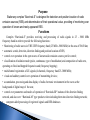
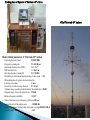
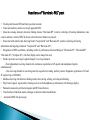
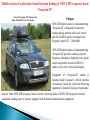
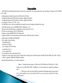
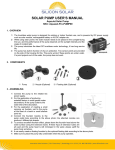
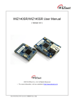
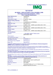
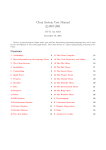
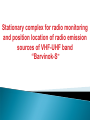
Stationary complex for radio monitoring and position location of radio emission sources of VHF-UHF band “Barvinok-S” Purpose Stationary complex “Barvinok-S” is designed for detection and position location of radio emission sources (RES) and determination of their operational value, providing of monitoring over operation of known and newly appeared RES. Functions Complex “Barvinok-S” provides receiving and processing of radio signals in 25 - 3000 MHz frequency band in order to provide the following functions: • Monitoring of radio waves in VHF-UHF frequency band (25 MHz -3000 MHz) in the area of 50x50 km; • automatic search, detection, direction finding and position location of RES; • control over operation in the open waves of known radio emission sources put for control; • classification of radiation mode (pulse, continuous, type of modulation) and composition of radio nets, operating on fixed and hopped frequencies and (frequency hopping); • multichannel registration of LF-signals (4 channels, frequency band 25-3000 MHz); • visual and auditory control over operation of transmitting devices; • accumulation, processing and data display of radio electronic environment in the waves at the background of digital map of the area; • control over parameters and modes of operation of ‘Barvinok-RP’ stations of the direction finding network, and also over “Barvinok-M” type products when including them into direction finding network; • computer-aided processing of registered signals and RES databases. COMPOSITION OF “BARVINOK-S” COMPLEX 1. Stationary station of detection and direction finding of signals in VHF-UHF frequency band (25 MHz - 3000 MHz) “Barvinok-OP” – 1 set 2. Automated post for acquisition and signal registration of VHF-UHF frequency band (25 MHz - 3000 MHz) “Barvinok-PRS” – 1 set 3. Stationary (unattended) radio direction finding station of VHF-UHF frequency band (25 MHz - 3000 MHz) “Barvinok-RP” – 2…4 sets 4. Mobile station of radio monitoring and direction finding of VHF-UHF frequency band (25 MHz-3000 MHz) “Barvinok-M” («Scorpion-M») - 1 set 5. Man-portable direction finder “Philin-A” - 1 set Note. Quantity of “Barvinok-RP” (or Mobile Station «Scorpion-M») stations is determined with accordance to the size of the undercontrolled area and its geography. Stationary complex for radio monitoring and position location of radio emission sources of VHF-UHF band Barvinok-S - Radio direction finder station «Barvinok-RP» UHF-retranslator - WiMax equipment - Detector direction finder «Barvinok-OP» «Barvinok-RP» - Post of tracking and registration «Barvinok-PRS» - Mobile station«Barvinok-M» - UHF-retranslator «Barvinok-M» «Barvinok-RP» «Barvinok-RP» «Philin-A» «Barvinok-RP» Radio control station («Barvinok-RP», «Barvinok-RP») SRE 1 SRE 1 Main technical parameters Panoramic analysis Coverage range 50 km and more Operating frequency band 25-3000 MHz Panoramic scanning rate up to 10 000 MHz/second Direction finding and position location Operating frequency band 25-3000 MHz Maximal rate of detection and direction finding up to 10 000 MHz/second Accuracy of position location 3% …5% of RES distance Transmission capacity of the system of RES position location in the complex not less than 10000 RES/hour AFS of «Barvinok-OP» and «Barvinok-PRS» stations Stationary system for detection and direction finding of signals of VHF-UHF frequency band (25 MHz - 3000 MHz) “Barvinok-OP” Purpose Station “Barvinok-OP” is designed for detection, direction finding of RES in the frequency band of 25 - 3000 MHz in order to obtain data about known and newly appeared RES in the area of station operation. Composition •Direction finding antenna feeder system (AFS-OP) consisting of three 7-element ring antenna arrays: – AFS-OP1 – 25–300 MHz frequency band, – AFS-OP2 – 300–1000 MHz frequency band, – AFS-OP3 –1000–3000 MHz frequency band, •UHF- converter, four-channel, in AFS-OP3 housing, •OPP unit – four-channel detector-radio direction finder 25 to 1000 MHz, •Receiver “Galaktika-U” – one-channel analogue/digit radio receiving device of auditory control and formation of fragments of LF and IF signals while recording, •Equipment of operator’s working place is designed for controlling product’s equipment, providing digital processing of received signals, their registration and technical analyses, and also for providing RES position location`. •Power supply system Note. Signals to “Galaktika-U” receiver inputs come from omnidirectional antennas AN1 and AN2 of nearby standing “Barvinok-PRS” station. Functions of “Barvinok-OP” station •Search, detection and bearing taking of newly appeared sources against real waves loading; •Monitoring of radio electronic environment together with radio direction finding stations “Barvinok-RP”; •Automatic measuring of detected signals parameters; •Issuing of commands for acquisition and position location for “Barvinok-PRS” station; •Transmitting of commands for acquisition automatically when detecting RES with features: priority, special; •Determination of quantitative composition of radio nets, operating on fixed and hopped frequencies (Frequency Hopping); •Digital registration of LF and IF signal fragments from the output of “Galaktika-U” receiver; •RES bearing taking with mapping of bearing lines on the map of the area; •Executing of commands for bearing taking coming from acquisition posts “Barvinok-PRS”; •Automatic synchronization of bearing collection by all stations included into direction finding network; •Detection, direction finding and auditory control of wide class of АМ, SSB, FSK, FM, PM signals, wideband transmissions and also frequency hopping; •Automatic processing of REE data (working time statistics: number of RES detected, intensity of their operation). Working place of Operator of “Barvinok-OP” station AFS of “Barvinok-OP” station» Main technical parameters of “Barvinok-OP” station •Operating frequency band 25-3000 MHz •Frequency scanning rate 2.5-10 GHz/sec •Instrumental bearing error (RMS) 1.0 ° ..2.0 ° •EM field sensitivity 3 - 30 µV/m •Real time frequency bandwidth 2.5 / 10 MHz •Probability of detection and bearing finding of radio signal > 0.9 •Minimal duration of signal to be detected and for its bearing to be taken 1 msec •Sensitivity of radio receiving channels 0.7-1.0 µV • Dynamic range according to the third order intermodulation > 80 dB •Dynamic range of received signals levels 120 dB •Relative frequency instability 0.5·10-7 •Time of detuning receiver frequency synthesizer 200 µsec •Spectral density of heterodyne noise – 100 dBc/Hz •Quality estimation of bearing taking and signal receiving RMS Θ/U dB µV • Remote control channel LAN Desktop of operator’s board of “Barvinok-OP” station Equipment of automated post of acquisition and registration of signals of VHF-UHF frequency band “Barvinok-PRS” Purpose “Barvinok-PRS” station provides multichannel receiving and digital registration of RES signals in the frequency band of 25 - 3000 MHz, and also provides tracking of defined RES at the frequencies, detected by “Barvinok-OP” product. Composition •Multichannel antenna feeder system (AFS-PRS) consisting of four-element ring array of directional antennas : – AFS-1 – frequency band of 120–450 MHz (4 items), – AFS-2 – frequency band 300–1000 MHz (4 items), – AFS-3 – frequency band 1000–3000 MHz (4 items), And also two omnidirectional antennas: AN1- frequency band of 25–1000 MHz and AN-2 – frequency band of 1000 – 3000MHz. •Unit of wideband input devices and switching of VHF-UHF band . •Rack of RRD-4ch – four-channel digital signal recorder on the basis of four receivers that provides receiving, digital processing and registration of radio signals in the frequency band of 25 - 3000 MHz. •“Galaktika-U” receiver – one-channel analogue/digit radio receiving device of auditory control and formation of fragments of LF and IF signals for registration . •Equipment of operator’s working place is designed for controlling product’s equipment, digital processing of received signals, their registration and technical analyses, and also for providing RES position location . •Server of communication channels with equipment of data receiving/transmitting, it provides complex operation through the following communication channels: WLAN, GSM communication channel for transmitting package data, telecode UHFchannel, optical communication line and double wire telephone line. •Power supply system. Functions of “Barvinok-PRS” post • Tracking after known RES and theirs position location;; • Visual and auditory control over newly appeared RES; • Interaction among stationary direction finding stations “Barvinok-RP” (control, collecting of bearing information, state control, auditory control of REE in the area where direction finders are placed); • Interaction with mobile radio directing finders “Scorpion-M” and “Barvinok-M” (control, collecting of bearing information and targeting of stations “Scorpion-M” and “Barvinok-M”); • Designation of RES coordinates, including results of synchronous direction finding of “Barvinok-OP”, “Barvinok-RP”, “Barvinok-M” (“Scorpion-M”), with their display on the map of the area; • Product provides receiving of signals through 5 receiving channels: -Four independent receiving channels for continuous registration of LF speech and manipulated signals simultaneously; - One receiving channel for executing tasks for acquisition (tracking, auditory control, fragments registration of LF and IF signal of up to 3000 kHz); • Database directing with direction finding results, their sorting, editing, activating and deleting; • Play back of signals registered by tracking receiver to the headphones synchronously with bearings display; • Parameters measuring of detected signals and RES classification; • Classification of radiation modes (analogue or discrete kind of modulation); • Automated REE data processing. Working place of “Barvinok-PRS” station Main technical parameters of “Barvinok-PRS” station •Number of receiving channels: 1 tracking channel 4 registration channels •Operating frequency band: - tracking 25-3000 MHz - registration 25-3000 MHz •Coefficient of directional antennas amplification 6-8 dB •Sensitivity of receiving channels 0.5-0,7 µV •EM field sensitivity 3-30 µV/m •Dynamic range according to the third order intermodulation > 80 dB •Dynamic range 120 dB •Real time bandwidth 2.5 – 3000 kHz •Remote control channel WLAN/GSM/UHF AFS of “Barvinok-PRS” station Stationary (unattended) direction finding station of VHF-UHF frequency band “Barvinok-RP” Purpose “Barvinok-RP” station provides signal processing in the frequency band from 25 to 3000 MHz in order to obtain information about emission sources both continuous and short term functioning as a part of “Barvinok-S” complex. Composition Direction finding antenna feeder system (AFS-OP) consisting of three seven-element ring antenna arrays: – AFS-OP1 – frequency band of 25–300 MHz, – AFS-OP2 – frequency band of 300–1000 MHz, – AFS-OP3 – frequency band of 1000–3000 MHz • UHF-converter, 4-channel, in the housing of AFS-OP3; • Omnidirectional antennas: AN1 – frequency band of 25–1000 MHz and AN2 - frequency band of 1 – 3 GHz; • OPP unit – four-channel detector-radio direction finder of signals in frequency band from 25 to 1000 MHz; • Receiver “Galaktika-U” – one-channel analogue/digit radio receiving device of auditory control and formation of fragments of LF and IF signals for registration; • Equipment of operator working place is designed for controlling product’s equipment, digital processing of signals received from “Galaktika-U”, their registration and technical analyses, and also for providing RES position location (when operating in Master mode); • Power supply system provides necessary voltage rates for component parts of the product. System of power supply provides uninterruptible operation during 10 min in case of power failure. Functions • Search, detection and bearing taking of newly appeared sources within preset areas of operating frequency band, providing subsequent direction finding results delivery to the system of emission sources position finding; • Control over already known sources put under tracking; • Automatic setting to the frequency of emission source following commands issued by “Barvinok-PRS” station and transmitting of direction finding results data to this station; • Automatic delivery of answers for bearing requests from master station (while scanning); Auditory control and registration of LF signals of sources detected; Disclosure of nets operating on fixed frequencies and hopped frequencies; Automated radio electronic environment data processing along with radio electronic environment data registration and accumulation; Interaction with stations from “Barvinok-S” complex through organized link. Working place of operator of “Barvinok-RP” station: Main technical parameters of “Barvinok-RP” station •Operating frequency band 25-3000 MHz •Frequency scanning rate 2.5-10 GHz/sec •Instrumental bearing error (RMS) 1.0 ° ..2.0 ° •EM field sensitivity 3 - 30 µV/m •Real time bandwidth 2.5 / 10 MHz •Probability of detection and bearing finding of radio signal > 0.9 •Minimal duration of signal to be detected and for its bearing to be taken 1 msec •Sensitivity of radio receiving channels 0.7-1.0 µV •Dynamic range according to the third order intermodulation : > 80 dB •Dynamic range of received signals levels 120 dB •Relative frequency instability 0.5·10-7 •Time of detuning receiver frequency synthesizer 200 µsec •Spectral density of heterodyne noise – 100 dBc/Hz •Qualitative estimation of bearing taking and signal receiving RMS Θ/U dB µV •Remote control channel WLAN / GSM AFS of “Barvinok-RP” station Mobile station of radio monitoring and direction finding of VHF-UHF frequency band “Barvinok-M" Purpose The purpose of mobile radio monitoring station “Barvinok-M” is to provide search, detection and direction finding of new RES in the frequency band from 25 to 3000 MHz, determines their coordinates and also provides analysis of received signals and tracks aver RES operation. Into the composition of the product secretly portable compact direction finder “Philin-A” operating within frequency range of 25 – 3000 MHz, is designed for automatic bearing sampling nearby detected RES position is included. Composition •Direction finding antenna feeder system (AFS-M-P) consisting of two seven-element ring antenna arrays (ARF-OP1 – frequency band of 25 – 1000 MHz, AFS-OP3 – frequency band of 1000 – 3000 MHz). Four-channel converter is included into the composition of AFS-OP3. to the composition of AFS-M-P two antennas tracking channel are included: active monopole operating in the frequency band of 25-1000 MHz and АN2 – discone antenna operating in the frequency band of 1 - 3 GHz; •Radioparent housing for AFS protection on the roof of vehicle; •UHF-converter 1 - 3 GHz and unit of wideband input devices and switching of VHF-UHF band; •OPP unit – four-channel analogue and digital detector finder that provides receiving and digital processing of radio signals in the frequency band of 25 - 1000 MHz; •“Galaktika-U” receiver – one-channel analogue/digit radio receiving device of auditory control and formation of fragments of LF and IF signals for registration; •Equipment of operator working place is designed for controlling product’s equipment, digital processing of received signals, their registration and technical analyses, and also for determination RES position location; •Navigation equipment (GPS-receiver with antenna and electronic compass ); •Equipment of data receiving/transmitting: - UHF-modem; - UHF radiostation;- GPRS-modem; •Power supply system provides necessary voltage rates for component parts of the product. Power supply system consists of diesel-engine electro station and uninterruptible power supply with additional accumulator that provides uninterruptible operation during 10 min in case of power failure; • Mobile Station “Barvinok-M” is mounted on the basis of Ford Transit VAN 330L Functions • Receiving and spatial processing of radio signals in the frequency band of 25 - 3000 MHz; • Joint RES detection according preset criteria and their receiving and bearing taking; • Indication/display of amplitude spectrum of detected signal; • Indication/display of amplitude spectrum of signal which bearing is being taken; • Determination of coordinates of detected RES with display of their position on electronic map of the area; • Informational interaction with “Barvinok-PRS” post through communication channels in remote control and homing mode; • Automatic synchronization of bearing collection of received signals satellite radio navigation system GPS; • Automatic setting following commands coming from “Barvinok-PRS” post and transmitting of data about direction to RES by request about specified source from “Barvinok-PRS “ post; • Reception of command for homing to RES position location from “Barvinok-PRS “ post and also messaging with operator of this post through UHF channel with information coding possibility; • Continuous automatic location of own position and space orientation by signals coming from GPS satellite radio navigation system and compass; • Control over operation of known put for tracking radio emission sources; • Spectral shape observation, auditory control and recording of LF and IF signals of detected RES in the frequency band of 25 to 3000 MHz; • Parameters measurement of detected signals and classification of radiation modes (analogue or digital modulation type); • Defining of network composition operating of fixed frequencies and hopping mode (Frequency Hopping); • Detection, bearing taking and position location of RES within near-field zone (0.5 – 1 km) in the frequency band of 25 – 3000 MHz using Secretly portable compact direction finder “Philin-A”. Station “Barvinok-M” on the base of Ford Transit VAN 330L vehicle Rear section of “Barvinok-M” station Working place of operator of “Barvinok-M” station Main technical parameters of “Barvinok-M” station •Operating frequency band 25-3000 MHz •Frequency scanning rate 2.5-10 GHz/sec •Instrumental bearing error (RMS) 1.0 ° ... 3.5 ° •Sensitivity by EM field 3 - 30 µV/m •Real time bandwidth 2.5 / 10 MHz •Probability of detection and bearing taking of radio signal > 0.9 •Minimal duration of signal to be detected and for its bearing to be taken 1 msec •Sensitivity of radio receiving channels 0.7-1.0 µV •Dynamic range according to the third order intermodulation > 80 dB •Dynamic range of received signals levels 120 dB •Relative frequency instability 0,5·10-7 •Tuning time of frequency synthesizer of receiver 200 µsec •Spectral density of heterodyne noise – 100 dBc/Hz •Frequency band of IF recording and real time frequency analysis 2.5 – 3000 kHz •Quality estimation of bearing taking and signal receiving RMSΘ/UdBµV •Remote control channel GSM/UHF Mobile station of radiocontrol and direction finding of VHF-UHF frequency band “Scorpion-M” View of “Scorpion-M” station on the basis of Skoda Octavia A5 «Scout» Purpose VHF-UHF mobile station of radiomonitoring “Scorpion-M” is designed for detection, bearing taking, auditory and visual control and also for RES signals recording in the frequency band of 25 – 3000 MHz. VHF-UHF mobile station of radiomonitoring “Scorpion-M” provides scanning of preset frequency subbands or frequency lists, spatial search and position location of RES by surface waves with vertical polarization . Equipment of “Scorpion-M” station is mounted inside Customer’s vehicle (minibus or motorcar). Inside the vehicle the following equipment is installed: high-speed panoramic detector finder VHF-UHF frequency band, executive direction finder of VHF-UHF frequency band and automated working place of operator equipped with Notebook communication equipment. Main features View of “Scorpion-M” station on the basis of UAZ-452 vehicle •Panoramic view with detection and bearing finding of signals within frequency band of 25 - 3000 MHz with the rate of 1 GHz/sec; •Range of operation within radiovisibility: - 20-30 km in frequency band of 25-500 MHz; - 5-10 km in frequency band of 500-3000 MHz; •Simultaneous direction finding of signals in the frequency band and executive direction finding on fixed frequencies; •Automatic detection and bearing taking of modern radio systems sources (satellite communication lines Turaya and Iridium), including Frequency hopping (FH with V≤500 hops per second) basing on correlation and vector method; • • • • Real time bandwidth while detection-direction finding 10 MHz; Real time bandwidth while direction finding 10 MHz; Analysis and digital recording of IF (with band of 3 MHz) LF signals; Bearing taking of mobile phones GSM 900/1800 MHz under “catcher” control Composition • VHF-UHF direction finding antenna feeder system in the vomposition of two ring antenna arrays each consisting of 7 elements (25-1000 MHz and 1-3 GHz); • radiotransparent automobile cargo box of Thule Pacific 200 type; • Azimuth omnidirectional VHF-antenna of tracking equipment (optional); • Azimuth omnidirectional UHF-antenna of tracking equipment (optional); • two-channel converter of 1-3 GHz – 2 pcs.; • 20-1000 MHz receiver with two independent two-channel sections of analogue and digital processing; • VHF-UHF tracking receiver (AOR5000, R2500, “Galaktika-U” etc.) • Operator board on Notebook base (configuration not less than Intel Core i5); • GPS-receiver with antenna: GPS-18 USB (Garmin); • Electronic compass HMR300-D21-232 (Honeywell); • Equipment of data receiving/transmitting (telecode modem, UHF-radio station, antenna); • GSM-modem (3G/GPRS, 900/1800 MHz); • Power supply system including: - Distribution board; - Notebook AC adapter; - Power supply unit of the station; - accumulators (2 pcs.); - Power supply cables; • Set of connection cables and antenna feeders; • Complete set of spare parts and accessories (Single SPA), including units of field heterodines DG-20М (30-1000 MHz), DG-33М (1-3 GHz); • “catcher” equipment GSM 900/1800 MHz– optional; • Operational documentation (user’s manual and guide). Notes. 1. Omnidirectional antennas of VHF band (25-1000 MHz) and UHF band (1-3 GHz), tracking receiver (AOR-5000, R2500, “Galaktika-U), and electrostation are supplied by additional order. 2. Decision of vehicle selection should be confirmed with Manufacturing Company. Roof of the vehicle should be of size not less than 2.0х2.8 m, access to the rear section of the vehicle should be present. Placement of “Scorpion-M” equipment Direction finding AFS Two 2-channel receivers of detector-finder and executive direction finder Operator working place Electrostation HONDA (2.0 kWt) Technical parameters Panoramic detector-finder: •Operating frequency band •Real time frequency band 25-3000 MHz 2.5 / 10 MHz •Instrumental frequency scanning rate with detected signal processing: Frequency resolution FFT, kHz 3.125 6.25 12.5 25 Instrumental detection rate with bearing taking GHz/sec 0.15 0.3 0.6 1 Instrumental detection rate with bearing taking GHz/sec 0.9 1.8 3.6 6 •Instrumental error of signal bearing taking: in the frequency band of 25-200 MHz 5.0° (RMS) in the frequency band of 200-1000 MHz 2.0° (RMS) in the frequency band of 1000-3000 MHz 2.0° (RMS *- on the basis of UAZ-452 •EM field sensitivity (SNR=10 dB, BW=12.5 kHz): in the frequency band of 30-50 MHz 15 - 40 µV/m in the frequency band of 50-1000 MHz 15- 30 µV/m in the frequency band of 1000-3000 MHz 15-40 µV/m •Probability of detection and bearing finding of signal with duration of 5 msec when scanning in frequency band of 10 MHz > 0.9 •Minimal duration of signal to be detected and for its bearing to be taken 2 msec •Sensitivity of radio receiving channels (SNR=10 dB, BW=12.5 kHz) •Dynamic range according to the third order intermodulation : •Dynamic range of received signals levels •Suppression of spurious receiving channels •Suppression of spurious receiving channels •Time of detuning receiver frequency synthesizer •Spectral density of heterodyne noise (increment 25 kHz) •Qualitative estimation of bearing taking and signal receiving < 1.0 µV > 75 dB > 120 dB > 80 dB ±2·10-7 <200 µsec – 100 dBc/Hz RMS Θ/U dB µV Executive direction finder: • Operating frequency band 25-3000 MHz • Instrumental frequency scanning rate *: in the frequency band of 25-200 MHz 5.0° (RMS) in the frequency band of 200-1000 MHz 2.0° (RMS) in the frequency band of 1000-3000 MHz 2.0° (RMS) *- on the basis of UAZ-452 • Electric field sensitivity (BW=12.5 kHz): in the frequency band of 25-200 MHz, 5.0° RMS 15-30 µV/m in the frequency band of 200-1000 MHz, 3.0° RMS 10-25 µV/m in the frequency band of 1-3 GHz, 3.0° RMS 15-30 µV/m • Signal bearing taking in frequency band 2.5…3000 kHz • Signal demodulation for listening: SSB 2.5 kHz; CW, AM 2.5; 6; 10; 12 kHz; NFM 6; 10; 12; 18; 25; 50 kHz; WFM 100; 150; 280 kHz. • Signal receiving and recording in frequency band • Sensitivity of radio receiving channels (SNR=10 dB, BW=12.5 kHz) • Dynamic range according to the third order intermodulation • Dynamic range of received signals levels • Suppression of spurious receiving channels • Relative frequency instability • Time of detuning receiver frequency synthesizer • Spectral density of heterodyne noise (increment 25 kHz) • Qualitative estimation of bearing taking and signal receiving • Total duration of continuous recording to HDD of signal with frequency band of 300 kHz 2.5…3000 kHz < 1.0 µV > 75 dB > 120 dB > 80 dB ±2·10-7 <200 µsec – 100 dBc/Hz RMS Θ/U dB µV is defined by capacity of HDD (300 Gb – 180 hours) General parameters • Total power consumed by the station form DC power supply • Time of operation from fully charged accumulators • Operating temperature range of: - Equipment placed inside the vehicle - Antenna feeder system Rear view of “Scorpion-M” station < 160 W more than 8 hours + 5° С … + 40° С; – 30° С ... + 60° С. Equipment arrangement inside “Scorpion-M” station Desktop of operator board of “Scorpion-M” station Compact man-portable direction finder «Philin-A» Purpose Direction finder «Philin-A» is made for detection, reception and direction designation for radio emission sources with vertical polarization in the frequency band from 25 MHz to 3000 MHz within preset channel or while scanning the receiver through over channels. Radio direction finder “Philin-A” is a compact man-portable direction finder with automatic bearing sampling and it contains antennas set. Composition •Antennas set including: - AFS-1D – antenna for frequency band 25 – 200 MHz; - AFS-2D – antenna for frequency band 200 – 800 MHz; - AFS-3D – antenna for frequency band 800 – 3000 MHz. •Receiver IC-R20М - purposed for searching working frequencies of RES within preset frequency subband and their hearing. •DF-processor unit - made for bearing values determination computed in the result of spatial and time signal processing from the output of amplitude detector receiver •Remote control board (RCB). •Visualization unit – Pocket computer Asus A696, provides informational change with DF-processor unit through Bluetooth, and also provides control and visualization functions. •Headphones. •Charging unit for accumulators. Peculiarities 1. Antenna devices of the product are hidden under operator’s clothes. 2. Receiver IC-R20M, DF-processor unit and pocket computer are placed on the belt of operator. Functions Operation of the product provides fulfilling of the following functions: • in manual mode – bearing taking of RES signals by turn of operator’s body and designation of direction to the source of the signal being received by tone changing with instrumental error not more than of 20 degrees (RMS); • in automatic mode – diagram RES signals bearing taking with instrumental error not more than 25 degrees (RMS) and auditory listening of bearing sample and signal level; • hearing of the signal being received during bearing taking process; • receiver IC-R20M provides signals receiving both in autonomous and automatic modes of operation. Main technical characteristics of «Philin-A” •Operating frequency band: •Receiving and measuring device 25 - 3000 MHz Antenna of AFS -1D 25 - 200 MHz Antenna of AFS -2D 200 - 800 MHz Antenna of AFS -3D 800 - 3000 MHz •Sensitivity by the field is not more than in both modes of operation: 70 - 300 µV/m in frequency subband 25 - 200 MHz; 40 - 150 µV/m in frequency subband 200 - 800 MHz; 150 - 1000 µV/m in frequency subband 800 - 3000 MHz; •Minimal duration of signals for their bearings to be taken in automatic mode is - 300 ms. •The product is to be operated under field conditions in open air within operating temperature range from minus 10 С to plus 50 С (apart from Pocket computer). •Time of uninterruptible operation of the product from main accumulator battery and additional charged beforehand accumulators is not less than 8 hours. Equipment of “Philin-A” direction finder View of “Philin-A” direction finder