1
Training Manual
Basic Training – Version 5.50
August 2003
Copyright 2003 EPLAN Software & Service GmbH & Co. KG.
EPLAN Software & Service GmbH & Co. KG assumes no liability either for technical or printing errors
nor for deficiencies in this technical information and cannot be held liable for damages that may result
directly or indirectly from delivery, performance, and use of this material.
This document contains information on the basis of a proprietary system that is protected by copyright
laws. All rights reserved. This document or part of this document may not be copied or reproduced by
any other means without the previous permission of EPLAN Software & Service GmbH & Co. KG.
The software described in this document is subject to a license agreement. The software may only be
used and copied within the scope of this agreement.
®
EPLAN® and LOGOCAD TRIGA are registered trademarks of EPLAN Software & Service GmbH &
Co. KG.
®
®
®
®
®
MS-DOS / Windows NT / Windows 2000 / Windows XP / Microsoft Windows are registered
trademarks of Microsoft Corporation.
Microsoft® Excel® and Microsoft® Access® are registered trademarks of Microsoft Corporation.
®
RITTAL is a registered trademark of the Rittal Werk Rudolf Loh GmbH & Co. KG.
®
Clip Project is a registered trademark of the Phoenix Contact GmbH & Co.
®
INTERBUS is a registered trademark of the Phoenix Contact GmbH & Co.
®
®
®
ÖLFLEX , ÖLFLEX-SERVO and ÖLFLEX CLASSIC are registered trademarks of the U.I. LAPP
GmbH.
AutoCAD® and Volo™View Express are registered trademarks of Autodesk, Inc.
®
SIMATIC HW Config is a registered trademark of Siemens AG.
SCAN® is a registered trademark of McAfee Associates.
PKZIP/PKUNZIP® are registered trademarks of PKWARE, Inc.
®
ObjectStore is a registered trademark of eXelon Corporation.
D-ISAM® is a registered trademark of Informix Software, Inc.
Hardlock E-Y-E® is a registered trademark of Aladdin Knowledge Systems, Ltd Int..
®
InstallShield is a registered trademark of InstallShield, Inc.
®
PMS is a registered trademark of PMS Compelec GmbH.
®
MicroStation is a registered trademark of Bentley Systems.
All other mentioned product names, trade names and company names are trademarks or registered
trademarks of their respective owners.
Note: The hardware requirements indicated by the operating system manufacturers must be
considered. Hardware combinations that according to the manufacturer’s specification cause
malfunctions may also have an effect on the operation of EPLAN LOGOCAD TRIGA. Therefore an
accurate basic installation of hardware, operating system and hardware drivers (e. g. graphics board
driver etc.) is essential for a smooth operation of EPLAN / LOGOCAD TRIGA. Therefore the main
conditions and areas of application specified by the hardware manufacturers also apply to the operation
of EPLAN / LOGOCAD TRIGA.
EPLAN 5 Basic Training
Topics and Contents
Basic Working Methods
•
•
•
•
•
Defining personal directory settings
Editing projects
EPLAN page types
Using the working window of graphics editing
Using macros
Automatic Evaluations
•
•
•
•
•
•
Generating cross-references and associated lists
Contactor selection
Terminals
Cables
Creating a table of contents
Backing up data
Exercises
•
Creating a sample project incl. data backup
EPLAN 5 Basic Training
Defining Personal Directory Settings
Utilities > Parameters > Personal > Directories
The Directories option under the personal parameters is used to specify the
directories in which the programs should search for specific files. The individual
EPLAN files are distributed among the following different directories:
Projects:
In EPLAN, projects are saved in the directory \EPLAN4\P. This directory is created
during the installation and cannot be changed by the user. But it is possible to create
subdirectories under this directory in order to make project management easier.
Master data:
These include symbol files, plot frames, parameters, and plot forms. Print forms are
filed in a separate directory (refer to "Print, control forms").
Macros:
Macros must be filed in a directory below EPLAN4\M, otherwise the program will not
find them.
Parts data:
These are the files for the system-internal stock management. These include master
parts files.
Print, control forms:
These are terminal, cable, potential forms, and contactor lists as well as the forms for
the system-specific parts management program Plot forms are located in the master
data directory!
In addition, this dialog box displays the directories for:
•
•
Personal and workstation data
Temporary data.
These two settings serve for checking purposes and cannot be changed. In all fields
you can right-click to launch the pop-up menu and to assign the standard entry to the
respective field.
EPLAN 5 Basic Training
Use the [...] command button in order to branch to the Directory selection dialog box
and to select the directory interactively.
If you enter a directory that does not yet exist manually, the program will prompt you
if you want to create it now. The check boxes before the directory entries indicate
whether the respective directory exists or not.
When specifying the directories ensure that they are positioned within
the EPLAN4 directory structure. All the projects must, for example,
exist below the directory \EPLAN4\P\ or its subdirectory. If you
specify an invalid directory, EPLAN draws your attention to this fact
when you leave the dialog box. If you have specified several
directories which do not exist, you can decide whether EPLAN
should create all of them or only individual ones.
EPLAN 5 Basic Training
Editing Projects
The following overview provides a list of functions that are available in the Project
selection dialog box. For the most part, these functions can be carried out via
corresponding buttons in the dialog box as well as via menu options in a pop-up
menu. To call up the pop-up menu, the cursor must be located in the directory tree of
the Project selection dialog box.
Please note that the availability of the functions depends on whether
you have selected a directory or a project and if you are currently
editing the project properties.
EPLAN 5 Basic Training
Function
Action
New
Create a project/directory
This option can always be activated. Depending on
the subsequent option you select, either a new
project is created in the corresponding (sub)directory
or a new subdirectory is created.
Rename
Rename projects/directories
Using this function you can rename the project or
directory currently highlighted in the directory tree.
Copy
Copy projects
Activate this option and enter the drive, path, and
name of the project to be created in the subsequent
dialog box.
Delete
Delete projects/directories
Use this functions to delete projects or empty
directories. A prompt for confirmation is displayed
when you select this option.
Edit
Edit projects
This function is used to edit the project properties of
the currently selected project.
Save
Save projects
Use this function to save the project properties you
entered. The corresponding button or menu option is
activated when a new project is created, when
projects are copied, or when project properties are
edited.
Drives
Change the drive for the project selection
Use this function to have all drives displayed in the
directory tree that contain EPLAN projects. You can
then change the drive for the project selection.
EPLAN 5 Basic Training
Function
Action
Directories
Change directories
Use this function to influence the access to macros,
master and parts data as well as the print and
controls form for the currently opened project. This
option is only available as a button.
Selection
Select projects / delete selection criteria
Select the Create submenu option from the
Selection menu item if you want to preselect
projects for the directory tree. Select the Selection >
Delete menu items to remove the specified selection
criteria again.
Compress
Compress projects
This function is used to compress the currently
selected project.
Send by e-mail
Send projects by e-mail
Select this option from the pop-up menu in order to
send the selected project by e-mail.
Show user
If you select this function, you will get the information
which users are currently editing the project selected
in the project management.
Please note that the Show user function is part of an add-on module.
Only when the license for the module has been purchased can you
carry out this function.
EPLAN 5 Basic Training
Projects and Directories
EPLAN files projects in the \EPLAN4\P directory which is created when you install the
program. This directory cannot be altered. You can, however, create subdirectories
under this directory in order to make project management easier. These
subdirectories will be referred to as "project directories".
Projects include shared data not stored in the project directory. This is information
used by all projects and includes macros, master and parts data, as well as print
forms.
During the installation, a directory with your customer code is created in the various
directories. In order to keep your data separate from other customer-specific data,
you should create additional directories for each customer.
If you use special macros, parts data, or print and control forms for
customer "Smith", you should create the following directories for this
information:
\EPLAN4\N\SMITH
\EPLAN4\M\SMITH
\EPLAN4\L\SMITH
\EPLAN4\F\SMITH
For master data.
For macros
For parts data
For print and control forms.
Specifying the Project Type
When you create a project you also specify the purpose to which the project is to be
used in the project type. The following project types are available:
•
•
•
•
Schematic project
Symbol project: for editing symbols
Form project: for editing plot forms (for terminal diagrams,
interconnect diagrams, bills of materials etc.)
Macro library project: for editing macros which are to be used in the Schematics
Generator.
EPLAN 5 Basic Training
In EPLAN you will most often use schematic pages. However, a project can generally
be any of the above-mentioned project types. The project type can also be changed
subsequently: Thus you can change a schematic project at any time into a symbol or
form project.
This means that you can include, for example, sheets for plot forms, terminal
diagrams, interconnect diagrams, etc. in a schematic project and use them
correspondingly when required.
Specifying the Page Numbering Type
The page numbering type you specify determines how the project pages will be
managed. EPLAN supports the following page numbering types which you can
specify via the dropdown list box in the Page numbering type field:
•
•
•
Serial numbering
DIN page numbering
KKS page numbering (German power station numbering system).
The individual page numbering types are explained in the following sections.
Once you have created a project, you can no longer change the page
numbering type, because the structure of the database in which the
project is stored depends on the selected page numbering type. The
field is therefore grayed and cannot be edited when you call up the
"Project type" tab again later.
EPLAN 5 Basic Training
Serial Page Numbering
In this numbering type the pages are numbered consecutively. The page numbers
must lie within the range of 1 to 99,999.
In addition to the page number you can specify a subpage consisting of exactly one
number or character. This is advisable in particular if you have to include additional
pages when modifying an existing diagram or a list.
Examples are:
10
10.3
24.C
DIN Page Numbering
In the case of DIN projects the page designation can include a higher-level
assignment, a location designation or both, depending on the numbering type
selected.
EPLAN provides the following numbering types for the resultant combination
possibilities:
•
•
•
•
Higher-level assignment and describing location designation
Higher-level assignment and location designation
Location designation only
Higher-level assignment only.
The two upper types differ only in as far as a local designation specified at the type
"Higher-level assignment and describing location designation" is not used to identify
a page. Only the higher-level assignment is used.
In the second type "Higher-level assignment and location designation" both
identifiers are used for identification. In the other types the respective identifier used
exclusively - "Location designation only" or "Higher-level assignment only" - serves to
identify a page.
EPLAN 5 Basic Training
Sequence of the Identifiers
As a rule the individual identifiers are to be used in the following order for a page
designation to DIN:
•
•
•
Higher-level assignment (if appropriate, subpage)
Location designation (if appropriate, subpage)
Page number (if appropriate, subpage)
At the type "Higher-level assignment and describing location designation" at least
one of the two identifiers (higher-level assignment, page number) must identify the
page uniquely. The page number is unique in the following example:
=HLA.1+LOD.1/1
=HLA.1+LOD.1/2
At the type "Higher-level assignment and location designation" at least one of the
three identifiers (higher-level assignment, location designation, page number) must
identify the page uniquely. The higher-level assignment is unique in the following
example:
=HLA.1+LOD.1/1
=HLA.2+LOD.1/1
At the type "Only location designation" at least one of the two identifiers (location
designation, page number) must identify the page uniquely. The location designation
is unique in the following example:
+LOD.1/1
+LOD.2/1
At the type "Higher-level assignment only" at least one of the two identifiers (higherlevel assignment, page number) must identify the page uniquely. The page number is
unique in the following example:
=HLA.1/1
=HLA.1/2
EPLAN 5 Basic Training
Page Numbering according to KKS
Page numbering to the German KKS for numbering power stations is carried out
using the higher-level assignment and location designation. These identifiers are
preceded by one identifier each for the document type and the documentation type.
A page designation to KKS thus consists of:
•
•
•
•
•
Document type
Documentation type
Higher-level assignment (if appropriate subpage)
Location designation (if appropriate subpage)
Page number (if appropriate subpage)
Ensure that the page designations differ by at least one identifier.
The following expressions are thus valid page designations to KKS:
YD=HLA.1+LOD.1/1
YE=HLA.1+LOD.4/1
Specifying Subpages
In all page numbering types you can assign so-called subpages to the existing
project pages. This can be relevant, for example, if you have to insert additional
pages into an existing project.
Subpages are created by specifying the number of the corresponding main page,
followed by a numeral or a character.
In a project with serial numbering 10.3 or 24.C would therefore be valid designations
for subpages.
EPLAN 5 Basic Training
Specifying Designation Methods
Designations or identifiers are used to identify devices within an electrical project.
Devices include individual components, equipment, assemblies, functional units, etc.
that are each represented in the schematic by a graphics symbol. The identifier
provides the following information:
•
•
•
Interrelationships between the device and other parts of the plant
Mounting location of the device
Identification of the device by its type, counter number and function.
EPLAN supports the designation methods for devices, terminals, cables, and
interruption points specified in DIN 40719, Part 2.
EPLAN supports six device designations methods.
EPLAN 5 Basic Training
In the case of serial numbering the devices are identified exclusively by the device
designation. If you use the variation "with page prefix", the number of the page which
contains the device is prefixed to each device during evaluation runs.
For example, F1 becomes 19F1 if this device is used on Page 19 .
The same variations already known to you from page numbering are available for
numbering to DIN. Depending on the selected numbering method the higher-level
assignments and location designations are positioned at the front.
A component K1 which is to be displayed with the selected numbering
method "With identifying higher-level assignment and location
designation" is, for example, displayed as =HLA.1+LOD.1-K1.
Note that the specified numbering methods only have an effect on
automatic evaluation runs. Only the device designation is displayed
in the schematic.
Specifying the Designation Methods for Terminals, Cables, and
Interruption Points
EPLAN supports seven different designation methods for terminals, cables and
interruption points.
EPLAN 5 Basic Training
EPLAN Page Types
As a rule an EPLAN project consists of pages of different types. The page types can
be differentiated according to several criteria:
•
•
Logic page or graphics page?
Page created interactively or automatically?
Logic pages:
If a page was created as a logic page, this means that EPLAN can process the
information saved on it for the automatic generation of lists and diagrams.
Graphics pages:
In general, logic information cannot be stored on graphics pages for the automatic
evaluation.
Interactive pages:
These are pages that you create and edit yourself, such as schematic pages or free
graphics pages.
Automatic pages:
These pages are automatically created and processed by EPLAN. This includes all
pages whose data are first created during generation runs and then output as project
pages, e.g. terminal and interconnect diagrams, etc.
EPLAN 5 Basic Training
On the basis of the criteria mentioned above, the various page types can be
assigned to the following groups:
Group
Interactive
logic pages
Interactive
graphics page
Automatic
graphics pages
Special pages
Page types
Schematic,
PLC page,
Single-pole display
Free graphics,
Control-panel layout,
Plot frame creation,
Title page/cover sheet,
PLC overview
Table of contents,
Terminal diagram,
Terminal line-up diagram,
Terminal-connection diagram,
Interconnect diagram,
Bill of materials,
Device list,
Terminal-strip overview,
Cable overview,
Purchase-order list,
Wiring and wire list
External document
All pages belonging to one specific group are indicated by one standard symbol in
the page overview. For example, all automatic graphics pages have the
symbol
(see the section "Symbols used in the page overview"). An exception to this rule is
the interactive logic pages, as a symbol is used for pages of the Schematic and PLC
page type and another symbol for pages of the Single-pole display page type.
The following section provides an overview of the various EPLAN page types.
EPLAN 5 Basic Training
Page Type Overview
You determine the page type of a page while creating it. We recommend not to
change the page type when processing of the page properties later, since information
may get lost while doing so.
Whether menu items and functions can be activated in graphics editing depends on
the page type. For example, the insertion of symbols from symbol files is only
possible on logic pages (schematic pages, PLC pages, and pages in single-pole
display).
The J, K, L, M, N, O, P, R, S, U, V page types (automatic graphics
pages) are automatically created by EPLAN. Only if you want to edit
the forms in a forms project may it be necessary to manually create
pages of this type.
The following page types are available in EPLAN:
A = Schematic:
Schematic pages can access special functions associated with the creation and
evaluation of schematics. This includes inserting symbols with automatic wire as well
as functions taken into account during generation runs for terminal and interconnect
diagrams or for cross-referencing.
EPLAN 5 Basic Training
Using the Working Window of
Graphics Editing
The graphics editing module provides a specific window type - the working window for drawing schematics. The working window (also called "graphics screen" in the
documentation) are default Windows windows offering the familiar functions such as
Move, Minimize etc. In contrast to the two other window types (page overview,
message window) in graphics editing, it can only be placed within the main window.
A working window shows the graphics contents of an open page. If you have
modified an open page, EPLAN displays an asterisk in the title bar of the working
window to indicate this.
Example of the title bar of a modified page
EPLAN allows you to view several pages at the same time on the screen. For this
purpose you can open several working windows (see the section on "Opening pages
in a new window" in this User Guide). Even if several working windows are open at
the same time, pages can be edited in only one window at a time. The window
containing the page in which the current cursor movements and functions are carried
out is called the "active window". You can recognize this window by its colored title
bar.
EPLAN 5 Basic Training
Switching between Several Open Working Windows
If you want to change from one working window to another open working window,
simply click on it. In addition, the
key combination can be used for this
purpose.
Project > Graphics editing, output > Window
It is also possible to select the desired window via the Window menu. All open
working windows are listed in this menu. The active, topmost window is marked by a
preceding checkmark ( ). In this list, a modified page is marked with an asterisk
(see the highlighted third menu entry in the example). If more than 9 working
windows or pages are open, you can select the More windows... option to call up a
dialog box in which all open pages are available.
Example for the Window menu with several open pages
EPLAN 5 Basic Training
Closing all Working Windows
Project > Graphics editing, output > Window > Close all
To close all open pages or working windows at one go, select the Close all option
from the Window menu.
EPLAN 5 Basic Training
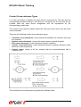
1. Editing Schematics
The ability to graphically display devices as symbols is the most important function in
the creation of schematics. In EPLAN you can only graphically show devices as
symbols on "logic" type pages (for example, on the Schematic or Single-pole page
type). In the following sections we will explain the multipole display. For information
on schematics in single-pole display, please refer to the section entitled "Creating
Schematics in Single-pole display".
Schematic extract with examples for the display of devices
Terminology:
The following terms are particularly important when working with symbols and
devices:
Symbols, device designations:
Electrical and mechanical devices are represented by graphics symbols in EPLAN.
A device in the project is identified by EPLAN by means of the device designation
(DD) you always have to specify in order to receive error-free evaluations.
Symbol files
EPLAN manages most symbols in symbol libraries - the so-called symbol files. You
can extend or edit them. Apart from the symbols you can insert from symbol files into
the schematic, there are symbols that are not linked to a symbol file, for example the
black box, the interruption point, or the device-end terminal.
Symbol properties
When inserting a symbol into the schematic, EPLAN opens a dialog box into which
EPLAN 5 Basic Training
you must enter symbol-specific texts or identifiers. These data are called symbol
properties. EPLAN evaluates the symbol properties during the various generation
runs. One of the most important symbol properties is the device designation.
Depending on the symbol you insert into the schematic, EPLAN displays various
fields for inserting symbol properties.
Wires
If the connecting points for device symbols lie opposite one another either vertically
or horizontally, connections between the symbols are generated automatically
("autoconnecting"). Angles and nodes are used to branch and divide wires. You can
use interruption points to continue a wire over a number of pages of the schematic.
Texts and hyperlinks
In addition to devices and wirings, it is also possible to insert special objects such as
texts and hyperlinks into the schematic in order to get a documentation that is
structured more clearly and to obtain additional information.
A hyperlink is a text inserted in the schematic providing a link to a document.
EPLAN 5 Basic Training
Using Macros
Macros are used in EPLAN to facilitate your work, as is the case in other programs.
You can combine several steps, such as the insertion of various components and
schematic elements with the assignment of device designations, to one step, that is
save as a macro and insert at a later point.
In general, macros consist of any sections of schematic or graphics pages in EPLAN
or include the entire contents of a whole project page. Furthermore, there are various
other macros, which provide specific functions.
The following sections first introduce these various macro types.
Then, further sections will follow dealing with the following subjects:
•
•
Defining a new macro
Using macros
Finally you will be familiarized with a specialized application of macros - the
Schematics Generator. With the Schematics Generator you can use standardized
macros to create your plant documentation without any drawing effort.
Macro types:
In EPLAN you can use six basic macro types and three special macro types. The
basic macro types are:
Macro type
Page macro
Window macro
PLC macro
Path macro
Variable macro
Combined macro
Character Schematic Graphics
S
x
x
F
x
x
L
x
P
x
V
x
Z
x
EPLAN 5 Basic Training
Every macro is saved in a separate file in the directory which you set for saving
macros in the parameter management module. The extension of a macro file name
provides information on the type and possible uses of the macro:
•
•
•
The first character of the extension is always M (for "macro").
The second character specifies the macro type - this is the Character column in
the table.
The third character of the extension specifies the page type on which the macro is
to be inserted: E for schematics pages and F for graphics pages. The table
columns Schematic and Graphics indicate whether a certain macro type is
suitable for the respective page type.
Not every type of macro can be created and inserted on every type of page. In
addition to the specified types there are further special macro types for which the
above rule on the file extension does not apply:
Macro type
Plot frame
Symbol macro
Control panel macro
Rittal control panel macro
Extension Schematic Graphics
SK?
x
x
MYS
x
MRS
x
DXF
x
Symbol Macros:
A symbol macro combines several individual symbols which represent a unit into one
object. Symbol macros are intended as a supplement to the symbol files. They are
saved with the .mys file extension.
Utilities > Parameters > Personal > Graphics
If you use the personal parameter "Symbol macros directory", you can specify that
symbol macros are not to be filed below the directory N for master data, but rather,
below the actual macro directory M.
For saving symbol macros we recommend to file them in a directory that is named
after the used symbol file in order to have a good overview.
\EPLAN4\N\<customer code>\DIC_WUP<X>\M3.MYS
EPLAN 5 Basic Training
Generating Cross-references and Associated Lists
Generate > Cross-references/wiring list
In this chapter you will learn how to update cross-reference data with various
generation runs and how to carry out several other functions. The respective module
is accessed by selecting the menu path Generate > Cross-references/wiring list
from the main menu.
Select Generate > Generate to open a selection dialog box. Here, you can decide
whether you want to start the listed generation functions as shown in the following
figure, individually or together.
If a generation run has been carried out before, EPLAN indicates this by setting a
check in the grayed fields on the right of the dialog box.
EPLAN 5 Basic Training
In the following sections you will find detailed information on the topics:
•
•
•
•
•
•
•
•
•
•
•
•
•
•
•
Generating cross-references
Creating wiring lists
Updating the text database and checking function texts
Creating and deleting wire numberings
Automatically correcting cross-reference errors in the schematic
Creating a list of special components
Deleting cross-reference databases
Editing cross-reference data
Outputting formatted cross-references
Deleting the contactor contact arrangement in the schematic
Outputting wiring lists as graphics pages
Evaluating messages produced during cross-reference generation
Setting parameters for the cross-reference display and output
Online cross-references when copying schematic pages
Online-updating of cross-references when renaming and deleting schematic
pages.
Generating cross-references:
EPLAN produces two types of cross-references in the schematic:
•
•
Contact cross-references
Interruption point cross-references.
EPLAN 5 Basic Training
The program automatically (online) inserts both cross-references into the schematic
while the project is being edited. Nevertheless we advise you to update the contact
and interruption point cross-references with a generation run. This is of particular
importance if:
•
•
•
Cross-reference changes result from loading macros and the individual
symbols/interruption points have not been confirmed with
in the graphics
editing module
You have modified page numbers, path numbers, or positions via the numbering
program
Projects have been created or modified by other programs.
In addition, EPLAN creates an exact error list when generating cross-references.
Error-free cross-references are a prerequisite for evaluating the following program
sections:
•
•
•
•
Wiring list
Contactor selection
Terminal and interconnect diagram
Device list.
You can use the correction function to have some cross-reference errors (as a
general rule, those errors that mostly occur) automatically eliminated.
Please refer to the following sections for more information on the topics:
•
•
•
Generating Contact Cross-references
Creating Interruption Point Cross-references
Generating Cross-references according to IEC 1082-1.
Generating Contact Cross-references
This subchapter is about the creation of contact cross-references. First, you will get
to know the various types of contact cross-references, and afterwards, you will learn
how to generate contact cross-references according to the IEC 1082-1 standard.
Finally, we will describe how to start a contact cross-reference run.
EPLAN 5 Basic Training
Contact Cross-reference Types
It is often necessary to display the same device several times. The fact that the
corresponding symbols belong to this device is recognized by the fact that all the
symbols have the same device designation and are represented by the
corresponding symbol type.
The contact cross-reference shows where the other part of the device can be found
in the schematic.
There are the following contact cross-reference types:
•
•
•
•
•
Contactor cross-references: (cross-references between the contactor coils and
the contacts)
Symbol cross-references: (cross-references between general symbols)
Pair cross-references: (cross-references between contacts).
Counter cross-references: (cross-references between symbols that were made
able to be cross-referenced)
Contact image: (image of all the contacts that are cross-referenced with a
contactor coil).
The individual cross-references are generated in different ways:
EPLAN 5 Basic Training
Contactor Cross-references
Coils and contacts are marked correspondingly when the symbol is designed in the
symbol editor. Here, the symbol type is specified which defines the symbol as coil or
contact symbol. A cross-reference to a coil symbol is drawn in the form of a contact
image whose appearance is defined in the graphics parameters.
Thus, coils and contacts are "by their nature" able to be cross-referenced, while other
cross-references are generated as a result of the respective elements having been
"made able to be cross-referenced".
Symbol Cross-references
General symbols can have a cross-reference assigned during schematic editing (can
be made able to be cross-referenced). This is the only case in which two symbols
(graphics symbols) can have the same device designation. The connections on the
symbols representing the device connections must have different connection
designations.
In symbol cross-referencing the individual symbols are identified as having a main
and one or more auxiliary elements. The settings required for this can be specified in
the Symbol properties input window that you call up in the Symbol type dropdown list.
Depending on the symbol type this list may contain different elements.
EPLAN 5 Basic Training
The following table lists the possible identifiers for the symbol type of the main and
auxiliary elements:
Symbol type
Standard symbol (not cross-referenceable)
Symbol as main element cross-referenceable
Symbol as auxiliary element cross-referenceable
Identifier
255
150
153
You can only enter part-specific (component-specific) data, such as the part number,
for a main element. You can assign n+1 components with the same DD to act as
auxiliary elements.
Pair Cross-references at Contacts
Cross-references between contacts are used to represent the interdependencies
between contacts when the component in question is not a contactor. This applies for
instance to the auxiliary contacts of a motor overload switch. In this case, two
contacts with the same connection designations are used in the schematic. That is,
the same DD or the same contact occurs twice.
Pair cross-references are entered in the same way as symbol cross-references:
Symbol type
Contact as a contactor contact
Contact with cross-reference below the symbol
(main element)
Contact with cross-reference next to the symbol
Contact with cross-reference below the symbol,
but rotated by 90°
Identifier
0-15
151
152
154
Notes:
Note that two symbols with both the same device designation and the
same connection designation may only be used if contacts have been
pair cross-referenced. In addition, the use of the same device
designation means that only half as many pairs can be used as the
maximum number specified in the "Maximum number of contactor
contacts" parameter.
Furthermore please note that it is not allowed to use symbol and pair
cross-references at the same time for one device designation.
EPLAN 5 Basic Training
Counter Cross-reference
The cross-references of contacts are placed below the device designation. For
symbols that have been made cross-referenceable, the same method is used as for
contacts.
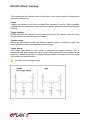
Contact Image
A contact image containing all cross-references to a coil is drawn below the
respective coil in the schematic. The appearance of the contact image is governed by
parameter settings. The contacts are listed in ascending alphanumeric sequence of
the connection designations. An exception to this are changeover contacts.
Extract from a schematic page with contact image
EPLAN 5 Basic Training
Starting a Contact Cross-reference Run
Generate > Cross-references/wiring list > Generate > Generate
Proceed as follows to start the generation process: Select Generate > Generate in
the Cross-references module. Then activate the Contact cross-reference / online DD
check box in the subsequent Generate dialog box. A checkmark in the grayed Run
carried out field indicates that a contact cross-reference run has been carried out
before. Once you confirm the dialog box by clicking [OK], EPLAN starts the contact
cross-reference run. If contact cross-reference errors occur in the project, EPLAN
outputs messages during the evaluation.
Creating Interruption Point Cross-references
This subchapter is about the creation of interruption point cross-references. First of
all, the terminology of the interruption point cross-reference is explained in the
following section. Finally, we will describe how to start a interruption point crossreference run.
Terminology of the Interruption Point Cross-reference
Interruption points are used to represent wires that go across more than one page.
The cross-references represent the reference to the page in the schematic on which
the wire continues. Target tracking is carried out at the same time. Target tracking
means that a target is searched for each interruption point. The target leads from this
interruption point to the next component.
EPLAN 5 Basic Training
The following section defines some of the terms used in the creation of interruption
point cross-references:
Target:
Targets are defined as all those symbols that represent a device. Other graphics
symbols such as angles and nodes cannot be targets, although they influence target
tracking.
Target tracking:
EPLAN searches for a target for every interruption point. The search continues along
the generated wires until a target is detected.
Counter target:
Where two interruption points that belong together appear on different pages, the
target DD always has a corresponding counter-target.
Target wiring:
The target information for the wiring is important for target tracking. This is
particularly true when nodes are used. If point wiring was used to draw nodes in the
graphics, a sensible definition for target tracking must be included so that the wiring
will produce the desired results.
Incorrect / Correct target wiring
EPLAN 5 Basic Training
Target Tracking along Interruption Points
Target tracking along interruption points is important for the following functions:
•
Display of the counter-target: You can use parameters to change the
information at the interruption point. Among other things you can also have the
counter-target displayed.
•
Determination of the wiring target: If a wire between interruption points leads to
another schematic page, the relationship between targets must be determined in
order for the wiring list to be generated.
Determination of the terminal targets: If an interruption point is connected to a
terminal, the interruption point's counter-target will be entered as the target during
the evaluation of the terminal data.
•
Identifier for the Interruption Point Check
Use the "Identifier for interruption point check" parameter to specify what kind of
interruption point check EPLAN is to carry out during the cross-reference run. The
individual options are explained in detail in the chapter entitled "Setting Parameters
for the Cross-references".
EPLAN 5 Basic Training
Starting an Interruption Point Cross-reference Run
Generate > Cross-references/wiring list > Generate > Generate
Interruption point cross-references are generated in a procedure analogous to that
for contact cross-references. Simply select Generate > Generate in the crossreference module, and activate the Interruption point cross-reference check box in
the subsequent dialog box. Here, too, a checkmark in the Run carried out field
indicates that you have already generated interruption point cross-references at an
earlier point in time. Once you confirm the dialog box by clicking [OK], EPLAN starts
the interruption point cross-reference run. If interruption point cross-reference errors
occur in the project, EPLAN outputs messages during the evaluation.
Generating Cross-references according to IEC 1082-1
Up to now, a cross-reference has in general been represented by a page and a path
specification, separated by a specific character.
The so-called path specification is the subdivision of a schematic page into several
columns marked by a number or a letter.
In many cases, an additional subdivision in line areas is required. This requirement is
based on the IEC 1082-1 standard, which corresponds to the EN 61082-1 standard
and which is supported by EPLAN as from version 5.50.
EPLAN now adds one letter to the cross-reference, which is placed ahead of the
path specification. This letter specifies the line area of the counter element.
EPLAN 5 Basic Training
In order to determine the line area, the current page is subdivided into equal
sections. The line sections are designated with ascending letters (A - F). The counting direction is from top to bottom.
A specific plot frame is required to subdivide the schematic page into line areas. For
this reason, the EPLAN installation includes the plot frame ESSG004D.SKG for the
cross-reference display according to ICE 1082-1.
EPLAN 5 Basic Training
The line division is carried out in the project-specific graphics parameters by making
an entry in the Line size input field. For detailed information on this parameter, refer
to the section "The Parameters on the Graphics 1 Tab" (User Guide II).
Notes:
The path and line specifications contained in the cross-reference do not
have an additional separator.
The specified cross-reference format applies to the schematic as well
as to all cross-reference specifications in databases or on generated
pages.
There isn't an offset for the desired subdivision. The subdivision starts
at the upper zero point and goes to the lower end of the sheet. The
beginning of the sheet (upper zero point) is the top edge of the plot
frame. The bottom edge of the plot frame represents the lower end of
the sheet.
EPLAN 5 Basic Training
Contactor Selection
Selecting Contactors Off-line
For off-line selection start the procedure after the schematic has been completed.
This lets you select all contactors in the entire project in one pass.
Generate > Contactor selection > Contactor > Select
Select the Contactor > Select menu items. EPLAN reads the project schematic
pages, starts a selection run (based on the parameter settings) for each contactor it
finds, and presents the part numbers and type designations of the appropriate
contactors or the appropriate combinations of auxiliary blocks in the Contactor
selection window.
It may occasionally occur that EPLAN cannot find a suitable contactor,
mainly if only a project-specific or general contactor list is used.
EPLAN then asks if the search should be continued, suggests all the
suitable contactors from the contactor specification file and changes
the selection run to the specified selection file for the next contactor.
The DD dropdown list box in the upper area of the Contactor selection dialog box
lists all the DDs contained in the schematic. The number of the currently highlighted
DD is displayed in the Contactor text box; under From: you will find the number of
DDs; this however only applies to the off-line selection.
EPLAN 5 Basic Training
The three list boxes below show the technical data for the contactor currently set
under this DD.
The window on the left lists the available contacts with the coils indicated before the
other elements of the contactor. The number of every element within the contactor is
displayed (Available) as well as the number of the already used and the unused
elements contained in the schematic.
EPLAN 5 Basic Training
The windows in the middle and on the right show the contact image of the contactor,
the window in the middle for the elements of the contactor, and the window on the
right for the elements of an auxiliary block possibly assigned to this contactor.
The upper two window entries are reserved for the coils and the other entries for the
remaining elements of the contactor or auxiliary block. In addition to its designation,
the two connection designations are displayed for each element.
An element is shown against a gray background in the contact image if it is already
used in the schematic. In addition, a red check mark is displayed on the left-hand
side of the element if the connection designation in the schematic is identical to the
connection designation in the contactor.
Furthermore the coil voltage and the contact rating are displayed for the selected
contactor. Depending on the parts program specified (EPLAN parts management or
other ERP) these data are taken either from the master parts file of from a transfer
file (extension .TDT). This requires that you have entered the contactor in the parts
file under a part number that is identical to the part number you entered in the
contactor specification file.
You will find a list box below in which you can select the contactors. For each contactor (and possibly the associated auxiliary block) the part number and the type designation is displayed. For the part number a variant may be defined (column "Var.")
Note that EPLAN also displays combinations of a single contactor with various auxiliary blocks.
Please note that you only transfer the contactor for the current device
by clicking on the [OK] or [Apply] button. Therefore it is not
sufficient to select several contactors and confirm the transfer of all
contactors by clicking on [OK].
At the bottom of the dialog you will find a group box. Here, you can adapt the
settings for the contactor selection selected in the parameter management for this
selection process. Only the selection file to be used cannot be changed here.
Please note that the two options Minimize unused contacts and Number
of unused contacts permitted have no effect in this case. In the case
of power contacts, all contacts are offered for selection.
EPLAN 5 Basic Training
When you click on the [Display] button the settings will become effective. Afterwards
the list box will be filled with the contactors valid under the selected parameter
setting. A warning message may also appear informing that no contactor could be
found for these settings.
In this case you have to use less "restrictive" parameter settings.
Online Contactor Selection
EPLAN also allows you to select contactors online. That is, while you are creating a
schematic. When specifying the properties of the main coil select the [Contactor
selection] button in the Symbol properties window.
EPLAN 5 Basic Training
EPLAN then initiates the selection run for the current contactor and loads the part
number, the connection designations, as well as the technical characteristics. You
can also use the online process to correct any errors found in individual contactors
during the off-line selection.
Using Existing Contacts
Once you have selected a contactor ([Contactor selection] button in the Symbol
properties dialog box for the main coil) you can have the unused contacts displayed
by clicking on the [Reserve contacts] button (in the Symbol properties for the other
contactor elements dialog box) and select them with the cursor after having highlighted a contact.
Contactor data are automatically updated online. This means that not only will the
part number and type designation be written back to the schematic, but all
connection designations as well. This applies to all pages on which contacts of the
contactor being currently edited are located.
Correcting the Contactor Selection
Generate > Contactor selection > Contactor > Correct
You can change individual contactor selections at the end of a selection run without
having to repeat the selection process for the whole project. First activate the
Correct menu item. A list containing the already selected contactors will be displayed.
In addition to the DD, the part number as well as the type designation are displayed
in the list for each contactor.
In this list you highlight those contactors that are to be corrected; it is possible to
highlight several contactors at once.
After having clicked on the [OK] button, change over to the familiar Contactor
selection dialog in which you can repeat the contactor selection.
Note that direct assignment of the part number without a check is only
possible in the graphic when you input the symbol!
EPLAN 5 Basic Training
Setting Parameters for the Contactor Data Output
Utilities > Parameters > Project > Contactor/cross-reference/wiring
On the Contactor 2 tab you can specify the parameters that influence the output of
the part numbers and of the type designations of the contactors in the schematic.
You can access the parameters either from the contactor selection module or via the
parameter-management function.
EPLAN 5 Basic Training
These parameters include:
Output identifier:
By entering "1" or "2", you can have the part numbers and the type designations
output above or below the contact image in the schematic. If "0" is specified, no
number will be output.
Output auxiliary block:
If you activate the check box, the auxiliary block will be output in addition to the part
numbers and type designations. In order for this to occur, you must have specified
either a "1" or "2" in the Part no. output identifier field.
Font size:
Use the dropdown list box to specify the font size in which the part numbers and type
designations of the contactors will be displayed in the schematic.
Alignment:
Here again you use a dropdown list box to specify whether the information will be
output left-justified, centered, or right-justified (relative to the path on which the
contactor coil is located).
Documenting the Contactor Selection
The Print option offers the following functions for printing the contactor data:
Print contactor specification file
Print selected contactors
Print contactors not selected.
The procedure is the same for all lists. The lists can be output to the printer, the
screen, or a file. Refer to the section "Specifying the Output Format for Printing" in
the User Guide II.
EPLAN 5 Basic Training
Defining Contactor Lists
Generate > Contactor selection > Contactor > Contactor lists
Contactor lists are used to limit the contactor selection to a part of the contactor
specification file in order to, for example, meet specific customer requirements
concerning the types of contactors you can use or to speed up the selection. EPLAN
offers two types of lists that you can define and activate after you have selected the
Contactor lists function from the Contactor pulldown menu.
•
•
Project-specific contactor list
General contactor list.
The file name of the project-specific contactor list is a fixed one. You can specify the
name of a general contactor list by either entering it in the text field under General or
by using the [...] button. Enter a new file name here in order to create a new general
contactor list.
EPLAN 5 Basic Training
You define a contactor list by highlighting data of the contactor specification file in the
left-hand area of the dialog box and then copying them to the area on the right-hand
button. You can also delete elements from a
side with a click on the
contactor list by highlighting them in list box in the right-hand half of the dialog box
and then clicking the
button.
By activating the Preview check box you can have the contact image for the currently
highlighted contactor displayed.
By clicking on [Apply] the selected contactors are saved in the respective contactor
list. In contrast to the [OK] button the window will not be closed so that you can
select and copy additional contactors or undo the selection.
Defining Contactors
This section describes the structure of the contactor specification file, how you can
add and modify contactor specifications, and how to import/export the contactor
specification data.
Entries in the contactor specification file are arranged by part number. These part
numbers should conform to the part numbers of the corresponding contactors in the
master parts file or in the TDT file (depending on the parts management used) so that
EPLAN can load the technical data for the contactor from this file.
EPLAN 5 Basic Training
Editing the Contactor Specification File
Generate > Contactor selection > Contactor specification > Edit
Select the Edit option from the Contactor specification pulldown menu. EPLAN
opens a dialog box in which you can enter the following information:
EPLAN 5 Basic Training
Part number:
The part number is the key field for the contactor specification file, that is EPLAN
uses the part number as the search criterion for contactor specifications. Therefore,
each part number must be unique and must be the same as the part number for the
corresponding contactor in the master parts file. (Among other things, the master
parts file manages information such as coil voltage and contact rating. In other
words, technical data for the contactor.) If the two numbers do not correspond or if no
number has been included in the master parts data, the bill of materials cannot be
generated correctly!
Type designation:
Like the part numbers, the type designation must be unique.
Contactor type / Group:
The identifier in this field specifies the type of contactor in question and the various
possible contactor/auxiliary block combinations.
Any three alphanumerical characters can be entered for the group. This way, you
divide the contactors into groups so that you can define possible combinations of
contactors and auxiliary blocks.
The following contactors were entered in a contactor specification file:
EPLAN 5 Basic Training
Part No. Contactor type
Group
AAA
Aux. contactor
(aux. block)
X
BBB
Aux. contactor
(aux. block)
Y
CCC
Auxiliary contactor
DDD
EEE
FFF
Auxiliary block
Auxiliary block
Auxiliary block
Explanation
Auxiliary contactor onto which
an auxiliary block can be
added. If the number of
contacts is insufficient, this
contactor is displayed
together with the auxiliary
block DDD for selection
(grouping X).
As for AAA, but can be
combined with the auxiliary
blocks EEE and FFF.
This contactor cannot be
combined. Grouping is
therefore not possible.
X
Y
Y
Part type:
Use this field to specify the part type under which the contactor or relay will be
managed in the master parts data. You can define the part as either an individual
part ("I") or as an assembly ("A").
Variation:
This field is used to define multifunction relays. Since these relays are all listed under
the same part number but can have a variety of contact configurations, this field is
used to differentiate between the individual variants so that EPLAN can also include
multifunction relays in the contactor selection process. EPLAN can then also use
multi-function relays during contactor selection.
Coil 1 / Coil 2:
Use these fields to define the coils for the contactor or relay, as well as the
corresponding upper and lower connection designations. By using the dropdown list
box you can select the symbol names of the coils from the symbol file specified in the
parameters under Symbol file.
EPLAN 5 Basic Training
Note that during contactor selection EPLAN compares symbol
numbers of the coils. In other words, if it encounters the coil symbol
"KT" in the schematic, EPLAN will also search the contactor
specification file for a coil designated as "KT". If you have not
defined a coil with this designation in the contactor specification file,
EPLAN cannot find a matching contactor. You should therefore take
care not to make any incorrect entries when making a manual entry.
Contacts 1 to 12:
Use these fields to define the contact configuration of the contactor or relay as well
as the contact's connection designations.
Note that during contactor selection EPLAN compares contacts by the symbol
number and symbol type. For example, for the contact symbol "SL" (normally open
power contact) with a symbol type of "0" (normally open power contact) in the
schematic, EPLAN will look for a contactor with an "SL" contact with symbol type "0"
in the contactor specification file.
If you have not specified a contactor with this contact in the specification file, EPLAN
cannot find a matching contactor. Note that while the symbol "S" (normally open) and
symbol type "0" also represent a normally open power contact, this designation is not
the same as "SL" and "0". Therefore ensure that you only enter valid symbol names
when entering them manually, and that you adapt the symbol type of the contact.
EPLAN 5 Basic Training
Symbol type:
In the Symbol type column you can have the symbol types of the entered coils and
contacts displayed and check them.
If a specific contact is to remain free assign the first entry (blank entry)
from the dropdown list box to it.
The individual command buttons of the dialog have the following effect:
[
[New]:
This function lets you re-create contactor specifications. The data of the contactor
last selected are retained as default values and can be revised.
[Change]:
Use this button to accept changes.
[Blank entry]:
Use this button to empty all fields in the dialog box. The previously displayed field of
the contactor specification file remains unchanged. After having filled the fields you
can transfer the entries by clicking on the [New] button.
[Delete]:
This function allows you to delete the record displayed in the Contactor specification
window after a prompt for confirmation.
[Close]:
Use this function to close the dialog box. A prompt for confirmation is displayed if you
have not yet saved the changes you made in the current record.
If you have specified new contactors or renamed existing contactors in
the contactor specification file, you should also enter the
corresponding records for the new contactors in the parts master
data.
EPLAN 5 Basic Training
Terminals
The next sections will provide you with information on the following topics:
•
•
•
•
Inserting Terminals
Multi-level Terminals in EPLAN
Defining Terminal Properties
Inserting PLC End Terminals.
Inserting Terminals
Terminals are considered to be devices and are inserted from the symbol file in the
same way as general symbols. The symbol name always begins with an X. Note that
EPLAN only evaluates these terminals for the terminal diagram. (However, the
evaluation programs recognize the terminal properties from the information on the
symbol type, not from the symbol name.)
EPLAN 5 Basic Training
Terminals are added in the same way as "normal" devices. Here too, a list window is
displayed from which you select the desired terminal, whereby the terminal's graphic
appearance is shown in a preview window on the screen.
When you have inserted a terminal at the desired position by single-clicking it, a
dialog box opens in which you have to enter the terminal's properties. You can
subsequently change these properties by positioning the cursor on the terminal's
or the left-hand mouse button.
insertion point and pressing
Since terminals and terminal strips are managed by EPLAN in a project-specific
database, you can use the system-supported terminal assignment function ([...] in
the Designation input field) to have the existing data displayed and to assign new
terminal numbers.
EPLAN 5 Basic Training
Note that an up-to-date terminal and interconnect diagram must exist!
In contrast to "X" terminals, device-end terminals that you add by either pressing
or activating the appropriate icon in the Insert toolbar are not treated as
devices. Instead, these terminals merely represent connections for devices and are
therefore not shown in the terminal diagram (cf. the section entitled "Inserting Deviceend Terminals").
Multi-level Terminals in EPLAN
Multi-level terminals are used when specific control panel or mounting panel
measurements must not be exceeded and thus a space-saving wiring is required.
A large number of terminal types is offered by the manufacturers which differ in the
field of application and in the designation. A rough difference is made between multilevel terminals with independent levels and multi-level terminals with connected
levels.
Multi-level Terminals with Independent Levels
This terminal type includes several terminals that lie one upon the other but have no
conducting connection.
The names usual in trade are:
•
•
•
•
•
•
Double-level terminals
Installation terminals
Initiator terminals
Actuator terminals
Shield terminals
Three-wire terminals etc.
A special form of these terminals integrates all connections of an initiator (e.g.
proximity switches) or actuator (e.g. valve coil). This results in an extremely high
wiring density. The highest level is used as passage for the signal line, whereas, for
example, on the middle level the minus potential and on the lowest level the plus
potential of the initiator power supply is distributed over snappable insertion bridges.
EPLAN 5 Basic Training
Multi-level Terminals with Connected Levels
A multi-level terminal with connected levels is a terminal that disposes of more than
two physical screwing possibilities. Since, according to DIN, two conductors can be
clamped under each screw, up to 12 conductors can be wired to a three-level
terminal (3 levels x 2 screws/level x 2 conductors).
The names usual in trade are also:
•
•
•
•
Distributor terminal
Shunting terminal
Three-wire terminal
Potential connector etc.
In EPLAN, multi-level terminals are defined by using the terminal properties (see next
chapter).
The special text 450 ("Levels") is available for the graphics output of multi-level
terminals into the terminal diagram. This allows you to define the level as well as the
jumper.
The following table provides an overview:
Definition in
form
Special text
450
Not available
Value = 0
Value <> 0
Output
Special text 400
As before
As before
All wire jumpers
(same position
as before)
Remark
Special text
450
No change to existing outputs
"0" corresponds to the
"standard terminal"
Output of level
as numeric
value
All jumper bars To graduate the circle diameter
(open circle, if more finely, the double
no jumper)
diameter for the font in relation
to the wire jumpers must be
selected!
EPLAN 5 Basic Training
Defining Terminal Properties
The properties of the terminal are defined in the Symbol properties dialog box. That
is, you determine how EPLAN will evaluate this terminal for display in the terminal
diagram.
Please note that specific fields in the Symbol properties dialog box
cannot be displayed or edited when you insert terminals /
connectors from a "single-pole" symbol file into a schematic page of
the "X = Single-pole display" type.
The following input possibilities are available on the Terminal / connector pin tab:
EPLAN 5 Basic Training
Designation:
Enter the terminal's device designation here. The designation can consist of the
higher-level assignment, location designation, terminal number, and terminal
subnumber. You can use the [...] button located next to the Designation field to
assign terminal designations system-supported.
Connection of the external output position in form:
In this entry you define the direction that is considered to be "external" when viewed
from the terminal in the schematic. The term "external" is used to specify a specific
location on the terminal diagram form. The terminal targets found by the EPLAN
search in the specified direction will be entered on the external side (position "A" and
"C") on the terminal diagram.
Connection for cable generation:
In this entry you specify in which direction from the terminal in the schematic cables
will be generated automatically.
The automatic cable generation is not possible on single-pole pages!
Utilities > Parameters > Project > Terminals/cables
The cable that will be used is defined by your entries in the Standard cable type,
Standard number of conductors, and Standard conductor cross-section fields of the
project-specific terminal-diagram parameters.
EPLAN 5 Basic Training
PLC designation:
If you use a terminal-diagram form which provides for the PLC designations to be
output, the text entered here will be output.
The text in this field can be translated online. The online translation function (see the
chapter on "Translating Texts Online" in the User Guide II) is started by pressing the
right-hand mouse button to call up the Foreign languages pop-up menu.
EPLAN 5 Basic Training
Function text:
Enter a function text of up to 255 characters for this terminal into this field. This text is
output in the "Function text" column of the standard terminal diagram. The function
text entered here can also be translated online.
Symbol number:
This field indicates the internal position of the symbol in the symbol file. Click on [...]
to change the current selection.
Angle variant:
This dropdown list box shows the existing angle variants for the current terminal.
Note that a change of this setting has an influence on autoconnecting!
Symbol type:
Enter the symbol type for the terminal here. The symbol type is evaluated during the
generation of the terminal line-up diagram. The type is used to differentiate between
the individual terminal types.
You can also launch the Selection of the terminal symbol type dialog box via the [...]
button and select the symbol type of the terminal there. The section "Symbol Type:
Terminal and Accessories" of the System Manual provides an overview of the
terminal symbol types.
Multi-level terminal on level:
If you activate this check box after having entered a "normal" terminal, this terminal is
defined as multi-level terminal. When specifying the level you determine the clamping
point in the terminal housing, thus the story or level.
If you select a level > 1 the Part tab disappears from the terminal
properties dialog box.
EPLAN 5 Basic Training
Terminal strip search direction:
Use the appropriate identifier to enter the direction in which EPLAN should search to
find the strip designation for this terminal.
Sorting identifier:
Use this identifier to specify how the terminal is to be sorted into the terminal
diagram. You can open the Terminal positioning dialog box via the [...] button, where
the position of the terminal on the associated strip can be changed.
Check identifier:
Use this identifier to specify whether the terminal may occur only once or several
times in the terminal diagram.
Jumper bars:
By entering the appropriate identifier in this field, you can specify whether you want
to define jumper bars for this terminal, regardless of the automatic evaluation. The
possible entries can be selected from the dropdown list box.
In addition to the terminal properties you can specify the display of the terminal
number or of the terminal-strip designation in the properties dialog box. This is done
by using the Text display tab, as is the case for "general" symbols from the symbol
file (see the section on "Defining the Display of the Symbol Texts" in this chapter).
Assigning Terminal/Connector Designations System-supported
Just like device designations, terminal or connector designations can be assigned
system-supported, too.
To do so, highlight the terminal or connector of any strip in the schematic, or insert a
new terminal or connector into an existing strip.
EPLAN 5 Basic Training
Afterwards click on the [...] button located next to the Designation field in the Symbol
properties dialog box for terminals or connectors (Terminal / Connector pin tab).
The Terminal selection dialog box that comes up provides an overview of all terminal
designations/connector designations used in the project for the terminal
strip/connector strip highlighted in the schematic or to which you have added a
terminal/connector in the schematic. Entries in round brackets signify that the
corresponding terminal/connector is actually used in the project. Entries without
brackets indicate spare terminals or spare connectors.
If you activate the Supplementary data check box, the cross-reference data and
connection targets for each terminal strip/connector strip that has been assigned are
displayed in the lower window.
Click on [Strip] to open the Strip selection dialog box which gives an overview of all
terminal strips/connector strips used in the project. Here you can select the strip
which you wish to assign to the inserted terminal/connector.
If you click the [Next] button, EPLAN will automatically suggest the next available
terminal number/strip number.
Confirm the suggested designation by clicking [OK]; it is then entered into the
Designation field of the Symbol properties dialog box. Finally click [OK] again, and
the new terminal/connector designation is read into the schematic.
You should already have generated a terminal diagram beforehand in
order to ensure that the terminal database has been updated and is
error-free.
EPLAN 5 Basic Training
Insert PLC End Terminals
PLC end terminals are used to display the circuit of sensor or actuator components at
PLC assemblies in the schematic. In EPLAN, PLC end terminals are used on pages
of the page type "Q = PLC page" as well as on pages of the page type "T = PLC
overview". Insert PLC end terminals on pages of the "Q" type to realize the byte-wise
connection assignment of PLC inputs and outputs of an I/O board. This is different for
page of the "T" type: you will need them here to create a board-oriented complete
overview of the connection assignment of all PLC input or output boards.
In EPLAN COMPACT you can also insert PLC end terminals in project
pages of the type "Q = PLC page" that have been created with the
full version. However, due to the limited functions compared to the
full version, EPLAN COMPACT does not allow to evaluate PLC end
terminals during generation runs.
In general, you must insert PLC end terminals into a black box to make PLC
assignments visible on T or Q pages. On PLC overview pages this black box is
inserted as "PLC box".
Note that after having inserted the black box into a PLC page you must
set the symbol number to "-13 = I/O boards" in the Symbol
properties dialog box. For detailed information on how you insert
black boxes into the schematic in EPLAN, refer to the section
"Inserting Black Boxes" in this chapter.
Now insert a PLC end terminal into the black box (or the PLC box) by following the
menu path Insert > PLC end terminal in the graphics editing module.
When the terminal has been placed, the Symbol properties dialog box is opened. In
the PLC end terminal tab specify the properties of the inserted terminal which EPLAN
requires for generating PLC cross-references.
EPLAN 5 Basic Training
Entering Symbol Properties for PLC End Terminals
The following entries can be made in the PLC end terminal tab:
Address:
Enter the full address of the PLC end terminal here. The address usually consists of
an identifier which marks the connection as input or output, a number for the byte
address, a separator, and a number for the bit address, e.g. O8.4 (Output, Byte 8, Bit
4).
By means of the PLC generator you can edit PLC addresses and write
them back to the schematic.
As an alternative to manual input you can also click the [...] command button to make
a system-supported address selection. EPLAN then displays all the PLC addresses
still available in the subsequent PLC address selection window. Which entries the
selection list contains, depends on the respective insertion situation:
Situation 1
You insert the PLC end terminal into an I/O board (black box with symbol type "-13"),
which already contains a device designation. In this case, the list in the selection
dialog box only shows the free addresses of the I/O board currently edited. Select the
desired address and confirm it by clicking [OK]. The address will then be written to
the PLC end terminal.
Situation 2
You insert the PLC end terminal into an I/O board which does not contain a device
designation. The list of the selection dialog box then shows the free addresses of all
I/O boards used in the project. When you highlight an address in the selection
dialog box and confirm with [OK], EPLAN takes over the device designation of the
I/O board contained in the address and writes it to the I/O board currently edited.
Please note that no DD is taken over at the I/O board if you manually change the
address after a system-supported selection has been made.
EPLAN 5 Basic Training
Situation 3
You insert the PLC end terminal outside an I/O board. The list of the selection dialog
box then also shows the free addresses of all I/O boards used in the project. Once
you select an address in the selection dialog box and confirm the dialog box with
[OK], EPLAN takes over the selected address at the currently inserted PLC end
terminal without considering the device designation.
If you want to change the symbol properties of several PLC end
terminal at one go by using the block editing function, it is not
possible to make a system-supported PLC address selection.
Corresponding address:
Numerous PLC manufacturers allow to feed sensors directly via operating-voltagecarrying terminals which are also contained on the I/O board. You can specify a socalled "Corresponding address" for these supply terminals to assign them to the
signal-transferring (addressed) PLC terminal. This field can only be edited if you have
selected Power supply for the Type of connection!
Connection description:
This field is used to enter a connection designation for one of the following
connection types:
•
•
•
•
•
•
•
Not specified
Digital input
Digital output
Analog input
Analog output
Board power supply
Bus
This field cannot be edited if the Power supply type of connection is selected!
EPLAN 5 Basic Training
Type of connection:
You can select among various types of connection for a PLC end terminal. The
following options are available:
•
•
•
•
•
•
•
•
Not specified
Digital input
Digital output
Analog input
Analog output
Power supply
Board power supply
Bus
Connection subtype:
In addition connection subtypes can be selected for the Power supply, Board power
supply, and Bus types of connection.
In case of Power supply and Board power supply you can determine whether the
connection has a plus potential, minus potential, or PE conductor potential, if it is
intended for the connection of a shielding or if it is not specified at all.
In case of Bus you can decide whether the connection is an input or an output or is
not specified at all.
Symbolic address: (not available on PLC overview pages)
If necessary, enter the symbolic address of the PLC end terminal here. Symbolic
addresses may contain symbolic names. This makes it easier to identify PLC
connections, e.g. "FEEMED2" for "Feeder Medium 2".
Supplementary field: (not available on PLC overview pages)
Use this field to enter general information for the PLC end terminal. This information
is displayed and plotted if the Show supplementary field parameter is activated under
Utilities > Parameters > Project > Graphics, Graphics 4 tab.
The text in this field can be translated online. The online translation function (see the
chapter on "Translating Texts Online" in the User Guide II) is started by pressing the
right-hand mouse button to call up the Foreign languages pop-up menu.
EPLAN 5 Basic Training
Function text: (not available on PLC overview pages)
A function description for the PLC end terminal is entered in this field. The text you
enter here, which may contain 255 characters, takes precedence over the function
text in the same path, which you can enter as a Function text text type. This
information is displayed and plotted if the Show function text project parameter is
activated (Utilities > Parameters > Project > Graphics > Graphics 4 tab).
The function description entered here can also be translated online.
Terminal display: (not available on PLC overview pages)
You can select between the following display modes in this dropdown list box:
•
•
•
With graphics: A terminal with a connecting point is drawn. If required, this
terminal is also shown in a black box.
Without graphics, designation lying outside: Only a connecting point is
specified. The wiring ends at this point. If you place this terminal inside a black
box, the connection terminates at the edge of the box. The designation of the
device-end terminal appears outside the black box.
Without graphics, designation lying inside: Same as above, but the terminal
designation appears inside the black box.
Connection designation: (only available on PLC overview pages)
Using this field you can specify the connection designations or numbers (pin
numbers) of the PLC end terminals on the I/O board.
Connection direction:
After the Insert > PLC end terminal or Insert > Device-end terminal function has
been selected, keep the
key pressed down and move the mouse up, down,
right, or left to rotate the connection direction. The original connection direction is
displayed in this field and can be modified.
EPLAN 5 Basic Training
By means of the property dialog box you can not only influence the PLC end terminal
properties but also the display of the PLC addresses. This is done by using the Text
display tab, as is the case for "general" symbols from the symbol file (see the section
on "Defining the Display of the Symbol Texts" in this chapter).
Notes:
To generate a cross-reference between schematic page and PLC overview page, the address and type of connection/connection subtype as
well as the device type must be identical.
A function text (Function text text type) can be specified at a PLC end
terminal when a PLC end terminal is inserted as well as when a text is
inserted in graphics editing. The function text for the PLC end terminal
takes precedence during the evaluation.
The connection designation entered on the PLC overview page at the
PLC end terminal can be written back to the PLC page by selecting the
menu path (from the main menu) Generate > PLC generator >
Generate > Write connection numbers back to schematic.
The function text as well as the symbolic address can be displayed on
PLC pages by opening the PLC generator module and then selecting
Parameters > PLC data.
EPLAN allows you to generate symbolic addresses by means of the
PLC generator. You can decide whether a DD target tracking is to be
carried out.
EPLAN 5 Basic Training
Cables
In EPLAN you can define the characteristics of cable definitions and of the wiring,
which will be used during the evaluation runs.
Use the Cable definition function to add specific cable definitions to the schematic by
hand. These definitions deviate from the general entries you made in the parameters
program. Definitions you add in this way will then be evaluated in both the terminal
and interconnect diagrams. In addition, you can also define a cable between two
symbols that are no terminals. Proceed as follows to define a cable:
•
•
•
•
Press
, or click the
icon in the Insert toolbar, or select the Cable
definition option in the Insert pulldown menu.
Use the mouse to specify the desired line.
Enter the corresponding data in the Symbol properties dialog box.
Finally, use the mouse to dynamically specify the text position.
Input Fields for the Cable Definition
Enter the cable-specific data, for example the cable designation, cable type, etc., in
the Cable tab. The following fields are available:
EPLAN 5 Basic Training
Designation:
Enter the cable designation into this field. When editing in accordance with DIN, you
can assign higher-level assignments and/or location designations by using "=" and
"+" as prefixes. The cable designation may consist of both numbers and letters. If the
cable designation does not start with a letter, the identifying cable letter defined in the
terminal-/cable-specific Cable identifier parameter is used. If you do not enter
anything in this field, the cable designation will be generated automatically for the
terminal or interconnect diagram. In this case the cable designation will be based on
the cable designation defined in the terminal/cable parameters.
The cable designation can also be assigned with the support of the system. For
detailed information refer to the following section "System-supported Assignment of
Cable Designations".
Type:
The cable type defines what kind of cable is being used. This is important when
assigning color codes and when the maximum number of conductors is considered. If
color codes are to be assigned or if there is a maximum conductor number, the cable
file must have an entry containing the name specified here and the corresponding
data. Use [...] to access the data already created.
No. of conductors:
If the form used contains a corresponding entry, the number of conductors entered
here will be imported into the terminal and interconnect diagrams. Enter the number
first. You can then enter an "x" as a separator between the number of conductors and
the cross-section. You must enter this "x" if you are using the standard forms
supplied by EPLAN Software & Service. In order to specify conductor pairs, you can
enter a second "x". If you do not want to use the unit of measure for the cross-section
that is specified in the parameters, enter the "x" separator as a capital letter.
The number of conductors specified for the respective cable type can be viewed, and
applied, by clicking on [...]. The "x" separator is then added automatically by EPLAN.
EPLAN 5 Basic Training
Cross-section:
If the form used contains a corresponding field, the cross-section entered here will be
imported into the terminal and interconnect diagrams. The maximum cross-section is
655. If the cross-section of a PE conductor is different to those of the other
conductors, you can use a "+" as a separator and thus enter two different crosssection values (e.g., 150+80mm2).
Keep the no. of conductors in mind for this specification. If, for example,
you entered a "4" into the No. of conductors field, and the entire
entry is therefore 4 x 1,5+2mm², the cable does not dispose of 4 but
of 5 conductors!
Length:
The value you specify in this field will be used during cable definition in the terminal
or interconnect diagram if a corresponding field exists in the diagram form. The
length can be entered with decimal values, or you can enter a unit in this field. An
entry depends on the type of form you are using. If you are using the standard forms
supplied by EPLAN Software & Service, you must define the unit of measurement. If
you do not specify a particular unit of measure, the value specified in the
corresponding parameter will be used.
EPLAN 5 Basic Training
Voltage:
The value for the voltage is entered in this field. It is not evaluated at present.
Special cable:
Use this check box to specify whether the cable is to be evaluated as a special cable.
This means that if the data of this cable differ from those of a cable of the same type
and this check box is activated, the "Differing cable data" message is suppressed.
PE conductor / Shielding:
Use the dropdown list box of these fields to specify whether the respective value in
the cable type file is to be used or whether you want to specify a different value.
There are the following selection possibilities:
• Automatic: The definition of the PE conductor / shielding is imported from the
cable type defined in the Cable type input field.
• Without: Even if the cable defined under Type provides for a shielding or PE
conductor, it is not created in the interconnect diagram.
• 1 PE / One-end: If this entry is selected, a shielding / PE can be generated.
• 2 PE / Both ends: Select the 2 PE entry if two PE conductors are to be allowed
for the cable. If the shielding is connected to both ends, this entry suppresses the
message "Two/several shielding conductors intersected".
Source/target:
Use this entry to specify whether the target designations in the interconnect diagram
should correspond to those of the terminal diagram or whether the target
designations are to be exchanged.
Use for print and graphics output:
If you activate this check box EPLAN will consider the cable specified here and
includes it in the printout as well as in the graphics output of the interconnect
diagram. This is the default setting. If the check box is deactivated the cable is
ignored during output.
Remark:
You can use this field to enter additional information about the specified cable
definition. The maximum length is 80. You can use any character except control
codes.
EPLAN 5 Basic Training
The entries made in the Designation, Type, Length, No. of conductors, Crosssection, Voltage, and Remark fields are displayed as cable definition texts on the
schematic page once the dialog box has been closed. If you want to display the cable
definition texts in several lines you must enter a line feed behind the respective field
or select the Line feed option
entry. To do this, press the key combination
from the pop-up menu after you have entered the text. In the text field, a line break is
represented by a " " symbol.
Text Display of the Cable Definition
In addition to the cable properties, you can also influence the display of the cable
definition texts in the properties dialog box. This is done by using the Text display
tab, as is the case for "general" symbols from the symbol file (see the section on
"Defining the Display of the Symbol Texts" in this chapter).
EPLAN 5 Basic Training
Line Data of the Cable Definition
You can determine the line type and thickness as well as the pattern length for the
actual line in the Line data tab (see the section on "Defining Line Data of Black Boxes
and Wirings" in the User Guide I).
The extension of an already defined cable line can also be
subsequently edited by calling up the pop-up menu on the insertion
point of the line and activating the Change size option.
EPLAN 5 Basic Training
Parts Data of the Cable Definition
Finally enter the part-specific information concerning the part number, number of
units, etc. in the Part tab. Use the [Select] button here to branch to the parts
management function and access the data saved there.
EPLAN 5 Basic Training
Displaying Cable Properties
The most important cable properties are displayed if you place the cursor on the
insertion point of the cable line, right-click to call up the pop-up menu, and select the
Display properties menu item.
Note that the Cable information window is only a display window, i.e. the cablespecific data cannot be edited here!
EPLAN 5 Basic Training
System-supported Assignment of Cable Designations
Apart from the manual assignment of cable designations, EPLAN also offers a
system-supported solution to designate defined cables.
If you want to use it click on the selection button ([...]) next to the Designation field in
the symbol properties dialog box for the cable. EPLAN then opens the Cable
selection dialog box.
This dialog box provides an overview of all cable designations assigned in the
schematic that have been defined by means of a cable definition line in the graphics.
EPLAN displays the cable properties of the currently highlighted cable in a separate
field below.
Wires that do not contain a cable definition line but that have been
generated by the automatic assignment of the cable designation are
not displayed in this dialog box.
There are two alternatives for the system-supported cable designation:
1.
2.
Highlight a designation listed in the selection dialog box, and confirm by
clicking [OK].
You want to use a designation that is not contained in the overview. To do so,
click the [Next] button. EPLAN then automatically suggests the next
designation that has not been assigned yet.
After you have confirmed with [OK] the selection dialog box is closed and the
selected or suggested designation is entered into the Designation field of the Symbol
properties dialog box. Finally click [OK] again, and the new designation is read into
the schematic.
EPLAN 5 Basic Training
Defining Shieldings
The Shieldings function lets you add the graphics symbol for the shielding of wirings.
You can use the mouse to define the size of the shielding. You must activate this
function next to the wires for which you want to add a shielding. You can use the
mouse to expand and rotate the shielding as required.
Shieldings can also be created by clicking the
button of the Insert toolbar.
The designation for shieldings entered in the terminal and cable parameters (menu
path: Utilities > Parameters > Project > Terminals/cables) is evaluated in the
terminal or interconnect diagram as the target designation.
In order to subsequently change the width or height of the shielding, position the
cursor on the shielding's insertion point and press
or the left mouse button. You
can then use the mouse to dynamically change the size.
To modify the graphics data of a shielding right-click on the insertion point of a
shielding to call up the pop-up menu and select the Attachment line type option.
Afterwards left-click on the insertion point of the shielding and modify the current data
for line type, line thickness, and pattern length.
EPLAN 5 Basic Training
Creating a Table of Contents
EPLAN allows you to enter page-specific information, for example for the page
designation or the supplementary page fields, on every page of your project. The
function for the table of contents creation is used to read out these data and present
them in the form of separate overview pages.
Extract from a table of contents
The next sections will provide information on the following topics:
•
•
•
•
Setting Graphics Output Parameters for the Table of Contents
Creating a Table of Contents
Updating a Table of Contents
Editing Special Text Coordinates in the Table of Contents Form
EPLAN 5 Basic Training
Setting Graphics Output Parameters for the Table of Contents
Various graphics output parameters allow you to adapt the format and the type of
output of the table of contents to suit your requirements. The following options are
available:
Using a Plot Form
To output the table of contents in project pages you must specify a corresponding
plot form using which you can influence the format of the table of contents.
Starting from the EPLAN main menu, follow the menu path Utilities > Parameters >
Project > Graphics output > Graphics form tab.
Enter the name of the desired plot form into the Table of contents field, or select the
plot form via the [...] button. The forms have the extension *.SKJ and are saved in
the directory EPLAN4\N. The check box in front of the field indicates whether the
respective form exists.
Influencing the Output
The output of the table of contents can be controlled via parameters that are located
in the Table of contents group box on the Graphics output tab. This tab is also
offered in the Graphics output parameters dialog box.
EPLAN 5 Basic Training
EPLAN 5 Basic Training
The following options are available:
Create subpages:
This parameter is important if the table of contents is longer than one page. You use
it to specify whether subsequent pages will be numbered as subpages or will be
sequentially numbered.
Character for subpages:
This parameter becomes important if the Create subpages check box was activated.
You can then specify the numbering style to be used for subpages.
If subpages have numerical designations, EPLAN can manage up to 9 subpages for
each primary page. In this case, the table of contents can have a total of 10 pages for
each primary page (the primary page itself + 9 subpages).
If the designations on subpages are alphabetical, EPLAN can manage up to 26
subpages for each primary page ("A" through "Z" or "a" through "z"). In this case, the
table of contents can have a total of 27 pages for each primary page (the primary
page itself 26 subpages).
If the project table of contents is too large to be displayed on the available subpages,
EPLAN automatically creates a follow-on page. In this case, EPLAN recommends a
starting page for the insertion of the table of contents, so that all pages in the table of
contents appear sequentially in the project.
Number of blank pages:
Use this parameter to specify how many pages will be left blank between the most
recently used page and the table of contents.
EPLAN 5 Basic Training
Round up to page:
This parameter, which operates together with the Number of blank pages parameter,
is used to specify the page number from which you want the table of contents to
start.
Both parameters are set as follows:
"Number of blank pages" = "4"
"Round up to page" = "10"
Case 1:
Let us assume the last page number is "47" --> The table of contents
will then start on Page "61".
Explanation:
The last page number is "47". You have to add 4 blank pages, which
results in "51" as last page number. This result is rounded up the
next full "10" so that the last page is "60". Therefore, "61" is the first
page number of the table of contents.
Case 2:
Let us assume the last page number is "46" --> The table of contents
will then start on Page "51".
Explanation:
The last page number is "46". You have to add 4 blank pages, which
results in "50" as last page number. This result is rounded up the
next full "10" so that the last page number is "50". Therefore, "51" is
the first page of the table of contents.
Output method:
Use this parameter to adjust the output of the table of contents to your project type. It
is, for example, possible to output a separate table of contents for each higher-level
assignment of your DIN project.
EPLAN 5 Basic Training
The dropdown list offers the following options:
• Entire output: This option enables you to output the entire table of contents at a
defined position.
• By higher-level assignment: This option allows you to output the table of
contents separately for each existing higher-level assignment.
• By location designation: This option allows you to output the table of contents
separately for each existing location designation.
• KKS: Using this option, you can output the table of contents separately for each
document and documentation type.
• Entire output and by higher-level ass.: This option enables you to output the
entire table of contents at a defined position and, in addition, by higher-level
assignments.
• Entire output and by location des.: Using this option you can output the entire
table of contents at a defined position and, in addition, by location designations.
• Entire output and KKS: This option enables you to output the entire table of
contents at a defined position and, in addition, KKS-oriented.
• Manual: Using this option you can highlight the pages to be output in the page
overview of graphics editing and manually define the page designation, the
starting page, and the output positions.
Creating and Deleting a Table of Contents
Project > Graphics editing, output > Extras > Table of contents > Create
The table of contents is an overview of all pages contained in the project. You create
it by following the menu path Extras > Table of contents > Create in graphics
editing.
EPLAN then reads the pages of your project and searches for a free space at which
the directory can be inserted. You can either accept or change the page EPLAN
suggests as the first page.
EPLAN 5 Basic Training
Check the results of the creation by calling the table of contents pages up in the
graphics editing module. You can change the parameter settings at any time and
repeat the generation run. The previous table of contents pages will be deleted
permanently from the project.
Furthermore, you can remove the table of contents from the project by following the
menu path Extras > Table of contents > Delete.
EPLAN 5 Basic Training
Updating a Table of Contents
Project > Graphics editing, output > Extras > Table of contents > Update
If you had already created a table of contents and added additional pages to the
project afterwards, the table of contents must be updated.
To this purpose, EPLAN provides an update function, which can be called up in
graphics editing under Extras > Table of contents > Update.
This function is also used if the page designation or the name of the creator was
changed on an already existing page.
EPLAN 5 Basic Training
Backing up Data
Much has been written about backing up your data. We will only spend a few minutes
adding our thoughts. Losing data as a result of, for example, damage to the hard
drive, a virus, or accidental deletion can have disastrous results for your company. In
order to lose as little as possible if the worst happens, you should:
•
•
•
•
Back up all projects that you are working on daily.
Back up projects prior to initiating global processing functions such as numbering
and evaluation runs.
Back up completed projects.
Back up master data such as symbol files after any modification.
Utilities > Backup
To access the data backup menu, first go to the main EPLAN menu, then select
Utilities and Backup. Before describing the various data backup functions we will
start by explaining a number of terms used when working with the data backup
module.
Terminology
File group
Project backup tasks differentiate between project-specific and non-project-specific
data (master data). File groups are stored behind the directories defined for EPLAN,
and each group contains files associated with specific task steps such as the macros
group, whose files are located behind the \EPLAN4\M directory.
EPLAN 5 Basic Training
Documentation Database
This database is managed by the EDOC program function and is used to provide an
overview of the projects. In particular, this includes information about when and
where a project was backed up, filed-off, or archived. For detailed information on
EDOC, please refer to the section "Editing the Project Documentation" earlier in this
chapter.
In the subsequent section you will find information on the various data backup
functions.
•
•
•
•
•
Defining Default Settings
The Backup Dialog Box
Backing up and Reloading Data
Compressing and Extracting Projects
Executing Special Functions of the Data Backup.
Defining Default Settings
Utilities > Backup > Parameters
Prior to a data backup, you may have to make various default settings. For this
purpose, the Data backup utility offers the following menu items or parameters:
•
•
Drive
Input / Output.
If you want to carry out a data backup via a control file, you must adjust the control
file beforehand. The following section gives details on the above-mentioned
parameters and the control file for the data backup.
EPLAN 5 Basic Training
Drive:
You can use the Drive menu item to temporarily change the "Data exchange drive"
(see below) specified in the input / output parameters.
To do this, select the drive on which you want to carry out a data backup or from
which you want to reload data in the Drive selection dialog box. All the available
drives are displayed.
If you click on the Save permanently check box, the drive selected here is applied as
Data exchange drive in the input and output parameters.
Input / Output:
Use the Input / Output menu item to define the workstation-specific parameters for
the data backup. The following parameters are available:
•
•
•
•
Data exchange drive
(This is the drive on which the data are saved during the data backup process or
from which the data are read during a reload process.)
Compress data
Use old backup format
Compression program directory.
EPLAN 5 Basic Training
Notes:
You can also specify the workstation-specific input and output
parameters in the parameter management under Workstation / I/O
parameters.
If you carry out the data backup with the COMPACT version, a
compression of the data is not carried out via the internal compression
program, even if the Compress data check box is activated
For further information on these parameters refer to the section "Specifying I/O
Parameters" in this User Guide.
Editing the Control File DATSICH.INF
In order to specify the extent of the backup you can the edit the control file
DATSICH.INF (in the customer-specific directory for the master data). Use the menu
items Extras > Edit control file in the Data backup dialog box. This function allows
you to define the extent of backup separately for each data group.
Utilities > Backup > Extras > Edit control file
EPLAN 5 Basic Training
The control file is an ASCII file that must be built up on a line-by-line basis. Each line
contains either a file specification or a control sequence.
All control sequences must begin with a period and define the respective file group.
The respective file group character is entered after the period. The following
assignments apply:
P
N
M
L
F
O
Projects
Master data
Macros
Parts data
Print and control forms
Personal and workstation parameters.
Each control sequence line is followed by one or more lines containing file
specifications. The use of the wildcard characters "*" and "?" is allowed in accordance with standard DOS conventions. "*.*" means that all the files of the directory are
to be backed up.
Example of a DATSICH.INF file
.P
Project directory
seiten.*
Graphics database
projekt.ppd
Project parameter file
ort.*
DIN file of location designations
anlage.*
DIN file of higher-level assignments
.N
Directory for master data
*.*
all files
.M
Macro directory
ESS????D.MSF
Page macros graphics pages
.L
Parts directory
*.*
all files
.F
Directory for print and control forms
EPLAN\*.*
All EPLAN form files
EPPS\*.*
All ERP form files
.O
Personal and workstation directories
*.*
all files.
EPLAN 5 Basic Training
Files specified with a preceding ":" will not be backed up. All other listed files will be
backed up.
If a colon is used for the identification, only the combinations of a colon with the
"file_name.*" or with the "*.file_extension" are allowed.
Examples of the identification with a colon for an extract from another
DATSICH.INF file.
.P
Project directory
:backup.*
e.g. backup.spl
:*.err
e.g. Epl0004.err
*.*
.M
"..."
Macro directory
This means that, in the project directory, all files except for the backup files and the
error files are backed up.
EPLAN 5 Basic Training
The Backup Dialog Box
The Backup dialog is called up when you have selected a project and wish to save it
or to send it by e-mail or when you wish to save non-project-specific data such as
macros.
The various options of this dialog box will be explained below. Depending on the
backup selected you do not always have all options available.
EPLAN 5 Basic Training
Specifying the Backup Method
There are three backup methods available:
Backup:
Backing up copies the project to the target data medium. In other words, the project
remains available in exactly the same form.
File off:
The file-off function is used to copy the project to the target data medium for
additional external editing or modification. The original project is then locked to
prevent any modifications being made to it. Thus, only the filed-off project can be
changed. You can, however, open the original project on a read only basis.
Filed-off projects are marked by special graphics symbols in the project selection
windows. If the project has been compressed additionally, a different symbol is used.
(Cf. the listing of symbols in the section "Backing up and Reloading Data" in this
chapter.)
Archive:
Archiving is used to file completed projects to a target data medium. The entire
original project is deleted from the current hard disk, leaving only an information file.
Archived projects are also identified by a special symbol in the project selection
windows.
Specifying the Extent of the Backup
You can specify the extent of the backup operation. That is, you can define which
files are to be included during data backup. Your options here are:
EPLAN 5 Basic Training
According to control file:
When this option is used, the system backs up only those files in the directories
specified in the control file. The control file allows you to precisely define which files
from which file groups are to be backed up.
The section on "Editing the Control file" in the previous chapter provides you with
more detailed information about the control file structure.
All files:
This option backs up all files belonging to the respective file group. This option is
primarily used when archiving data.
Selected files:
If you use this option, you can only back up those files that are required for project
pages. Files derived from the project pages, such as cross-references, terminal
diagram, and bill of materials, are not included in the backup.
Individual selection:
This radio button can only be activated if master data, macros, parts data, print and
control forms, or data from the personal directory are backed up. You can then
individually select the directories and files which are to be included in backing up.
Deleting files no longer required
The following settings are possible here:
Backup files:
This includes various backup files that are created during the execution of the
program, such as the backup pages, which are created before a compression is
carried out, etc.
Back-up pages (*.ASS):
Select this check box if you want to delete the backup pages that EPLAN generates
automatically in accordance with the setting of the personal 'Number of page in page
buffer' backup parameter.
EPLAN 5 Basic Training
Search databases:
This check box can be used to specify that the project-specific search results which
are written into the search database during certain actions are to be deleted.
Compressing a Project
You can use the radio buttons in this group box to compress your project during the
data backup.
This compression is a completely separate action from the project compression
function, and is performed by a separate EPLAN module which reorganizes the
project database. The function irretrievably removes any deleted pages from the
project and removes gaps in the database. The project can be examined at the same
time for data consistency.
In addition, you can continue to edit a compressed project with the standard EPLAN
graphics functions. Only the deleted pages can no longer be accessed.
The database compression can be started in the EPLAN main menu by
selecting Project > Compress page database. The section on
"Revising the Page Database" in this documentation will provide you
with further information on this topic.
Backing up General Type Files
If you have used general, not project-specific, cable- and connector-type files in your
project, you can use the two check boxes in this area to specify whether these are to
be backed up with the project data.
EPLAN 5 Basic Training
Backing up Associated Files
When you back up projects, you can also include certain files from other file groups
in the project. These files are required to display a project. These include symbol
files, combined and variable drawing macros and forms for terminal diagrams,
interconnect diagrams, etc. The following possibilities are available:
No backup:
The associated files will not be backed up. Select this option if you have already
separately backed up the other file groups.
Backup:
The associated files from the N: Master data and M: Macros file groups are backed
up. Their names are read from the project parameters (symbol files, plot forms) and
the project pages (symbol macros). Select this option if you want to send a project to
another EPLAN user, e.g. to allow him to edit it.
Backup with print forms:
This option will include all the print forms used in the project (as defined in the
parameters), together with the master data and the project macros.
Updating the Documentation Database
In order to update the information in the documentation database after a data
backup, you must create a log and activate the log function as well as create an
EDOC database before the projects are backed up and reloaded.
Backing up data also has an effect on the documentation database, since, for
example, archiving projects must be recorded in this database. The database
contains input fields for projects in which specific information concerning data backup
is recorded. If, in addition, you have also activated the logging function, the data
backup procedures will also be recorded in the log.
EPLAN 5 Basic Training
The fields in the right-hand area of the Backup dialog box have the following
meaning:
Backup number:
You can document up to three backup processes for each project. Each backup
action is given a number. You can enter this number in the input window that appears
when you initiate a data backup. The entry associated with the number you input is
replaced in the documentation database.
Backup medium:
The backup medium on which backing up is to be carried out is entered in this field.
The possible entries can be selected from the dropdown list box.
Number of media:
Use this field to enter the number of media needed.
Stored at:
You can enter the storage location of the medium into this field, e.g. Project archive,
Data safe, Personal archive. In addition, the data and time at which the backup was
carried out are entered in the documentation database.
EPLAN 5 Basic Training
Filing off Projects
If you have activated the File off for external processing radio button under Backup
method, you can enter the corresponding information for the project in the File off
group box.
Use the [...] button to launch the Customer selection dialog in which you can select
the customers for the To customer field. In this dialog box all customers are listed
who are stored in the customer master data of the parts management.
Saving the Defaults of the Backup Settings
In order to save the current backup settings as the default values, click the [Save
default setting] command button as soon as all the check boxes and radio buttons
have been set in accordance with your requirements. Whenever you call up the
Backup option again, these settings are then offered as the defaults.
Selecting a drive or sending an e-mail
Using the dropdown list box of the To field you can select the drive on which the data
are to be saved. If the data are to be sent as e-mail the @E-mail entry must be
selected from the list. How to send e-mails is explained under "Sending projects by email" in the section "Editing Projects" in this chapter.
EPLAN 5 Basic Training
Backing up and Reloading Data
Backing up a Project
When backing up projects to diskettes, we recommend that you have an adequate
number of already formatted diskettes available before you begin the backup
procedure. Then select the Backup > Projects menu items in the Data backup
module.
Irrespective of the project you are currently editing it is possible to select any project
on the current drive or via the [Drives] button also on another drive in the
subsequent Selection of the projects to be backed up dialog. Use [Reset] to set the
selection back to the project that was originally set in the Project selection dialog box.
Graphics Symbols in the Project Selection Function
The following graphics symbols are used to display the backup mode of a project in
the tree view of the selection dialog box:
Symbol
Backup mode
Current projects
Compressed projects
Archived projects
Filed-off projects
Filed-off projects, which have been compressed.
Afterwards the Backup dialog is called up in which you can specify the various
backup parameters. Also refer to the information on the Backup dialog box. Confirm
with [OK] to start the backup action. If necessary, you will be asked beforehand to
insert a backup diskette.
If the system notices that the backup medium is not empty, a message is displayed
and you can decide whether you still want to use it for the backup.
The result of the data backup is documented in the message management and
output to a window. When you confirm with [OK] you will be returned to the backup
module.
EPLAN 5 Basic Training
If all your project files do not fit on a single diskette, the additional diskettes will be
assigned the designation P and be given a sequential number. Note the name on the
label of the respective diskette.
Copying Projects for Data Exchange
When you copy projects to diskettes for the purposes of exchanging data, you should
take note of the following points when backing up the project:
•
If you use your own, unique symbol files, macros, plot forms, etc. in your project,
you must also supply the corresponding files so that the recipient can actually
work with the project. To this purpose select the Backup or Backup with print
forms radio button in the Project-specific files group box of the Backup dialog box.
•
If you only use those files that form part of the standard EPLAN delivery to create
your projects, you do not need to select the options mentioned above for backing
up associated files.
Backing up Further Data
In addition to those data already mentioned, the following file groups can also be
backed up with the data backup module (in each case, the base directory is shown):
Master data
Macros
Parts data
Print and control forms
Personal and workstation data
\EPLAN4\N
\EPLAN4\M
\EPLAN4\L
\EPLAN4\F
\EPLAN4\O
Once the desired menu item (e.g. Macros) has been selected from the Backup
menu, the Backup dialog box appears. Compared to the project data backup only a
few parameters can be specified here.
In the subsequent Directory selection dialog you can select the directory whose files
are to be stored. If the Individual selection option was set in the Backup type group
box of the Backup dialog box, a file selection must be made afterwards.
The further procedure to back up data corresponds to the procedure when backing
up project data.
EPLAN 5 Basic Training
Reloading Projects
To reload data, use the Reload menu of the Data backup module.
Utilities > Backup > Reload > Projects
If necessary, you will be asked to insert a diskette. After project selection in a
subsequent dialog box you can decide while reloading projects whether the project is
to be reloaded under its original name or whether you want to assign a new name.
If you confirm the original name, the project files are written back to the original
directory. If you enter a project name that already exists (or confirm of the original
name), a window appears asking you if you want the project directory to be
overwritten.
When reloading projects for which "project-associated files" were backed up as well
you will we prompted in subsequent dialog boxes how to proceed with the associated
files.
The reloading result is documented in the message management and output to a
window. Click [OK] to return to the data backup module.
EPLAN 5 Basic Training
Specifying Directories for Shared Data
When reloading projects, an additional dialog box is called up once the project name
has been specified. The Specify directories dialog box only appears for projects for
which the "project-specific files" were included in the backup. Enter the directories
manually here, or use the [...] buttons that will open a selection dialog box.
Use this dialog box to specify the directories for the shared data. By doing this, you
also determine the directories into which the associated files can be copied
afterwards.
Select an option from the Directory structure group box. The following options are
available:
Original as saved:
The directory structure of the reloaded project is applied.
Project-related:
The directory structure is copied from the directory that was specified in the previous
dialog box for the project name.
EPLAN 5 Basic Training
Currently set:
The directory structure of the currently selected project is applied.
The directories of the selected directory structure are shown in the fields below.
These directories can be changed which is useful if a different directory is to be used
e.g. for the macros. When you click [OK], the reload procedure will be continued and
you will be asked what should be done with the associated files.
Reloading Additional Data
Reloading other data (master data, macros, parts data, print and control forms,
personal and workstation files) is done in the same way.
After having selected the corresponding menu item from the Reload menu, you must
choose the directory of the data to be reloaded in the selection dialog box.
Afterwards you may change the target directory, if required. When doing so, the
respective base directory e.g. \EPLAN4\M for macros cannot be changed. When
finished, click on [OK] to return to the data backup module.
Compressing and Extracting Projects
Compressing Projects
You can reduce the space requirements of project files by compressing projects. This
function uses a so-called "compression program" to compress the files.
Decompressing the files extracts them from the compressed file.
Please note that you cannot edit compressed projects!
Select the Backup > Compress menu items to compress the current project in the
current working directory. To do this, the Clean project dialog box is launched. In this
dialog you can specify which of the files that are not needed for the data backup can
be deleted. After the prompt whether the existing backup files are to be deleted the
compression process is started.
EPLAN 5 Basic Training
In project selection, compressed projects are identified by a special
graphics symbol ( ) as well as by the text "Compressed" in the
project properties.
Example for the display of a compressed project in the project selection
Extracting Projects
If you select a compressed project for graphics editing, EPLAN points this out and
offers to extract it in a subsequent dialog box. As an alternative, the decompression
can also be directly started via the Reload > Decompress menu items of the Data
backup module.
EPLAN 5 Basic Training
Please note that in case you decompress data that were packed by the ARJ
compression program in an earlier EPLAN version (prior to EPLAN 5.50), you must
set a certain workstation-specific parameter. If this is the case, specify the directory
in which the ARJ compression program is loaded in the input and output parameters.
As an alternative, the directory can also be determined by a corresponding entry in
the PATH system variable (Control Panel).
Notes:
Projects can also be compressed and extracted within the project
management. To do this, select the Select, create, copy project
option under the Project menu item to call up project management.
Highlight the desired project(s) in the directory tree, and select the
respective Compress or Decompress menu item from the pop-up
menu. Unlike the process in the data backup module the Compress or
Decompress queries will not appear but the projects will be compressed
or extracted immediately.
If the project-specific directories do not correspond to the current
directories for the compression, the Directory selection dialog box
comes up. Select the Project-related setting here to backup the correct
directories during the compression.
EPLAN 5 Basic Training
Executing Special Functions of the Data Backup
Reloading the Backup
The Reload backup dialog shows a list of the last backup copies of the entire project.
The display contains the user, date, time, and the executed function.
To retrieve a backup copy highlight the corresponding line in the dialog box. Then
click on the [OK] command button. The process is started and the dialog box closed.
If you wish to delete a copy click on the [Delete] command button after having
highlighted the corresponding line.
The Reload backup dialog box can be called up as follows:
•
•
•
In the data backup module via the menu path Extras > Backup management
In the cross-reference module and in the terminal and interconnect diagram
module by following the same menu path
In the Move, Number, and Position functions of the generation runs by using the
[Undo] button.
In order to undo changes it is possible to create a backup copy for the project before
executing the Correction function, Move, Number and Position functions. To do this,
the Create backup check box must be activated before carrying out the respective
function. A backup is also generated when the page database is compressed.
Notes:
In EPLAN COMPACT, the backup management is not included in the
backup module, but can only be launched by clicking the [Undo] button
of the generation runs.
You can specify the number of backup copies to be created in the
parameter management function under Personal > Backup parameters > Number of backups.
Cleaning up Projects
Select Extras > Clean project to activate the Clean project dialog box used for
project maintenance. Files that are not needed for the data backup can be removed
from the current project through this dialog.
EPLAN 5 Basic Training
Furthermore this dialog box contains a function for compressing the databases.
Using this function the project requires less storage space and is examined at the
same time for data consistency. Database compression was already discussed under
"Compressing a project" in the section "The Backup Dialog Box".
The backup files, backup pages, as well as the search databases are also
described in the above-mentioned section since the deletion of these files can also
be carried out in the Backup dialog box (see subsection on "Deleting files on longer
required").
The following additional files can be removed through the Clean project dialog box:
Data exchange files (*.EXF):
When exporting a project to the data exchange format EXF the entire project is
converted to a file. This file that, by default, is called EPL_ASC.EXT and is stored in the
project directory can therefore become quite large and should be removed before the
data backup is carried out.
ASCII files (*.ASC):
Through the corresponding check box, ASCII files that may have been created in
different ways are removed from the project directory.
Page filter (*.SNS):
A page filter file is created in the project directory if a page selection is permanently
saved in graphics editing.
To clean the project activate the corresponding check boxes and confirm with [OK]. If
all functions are to be carried out click the [Mark all] button first and then click [OK].