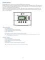
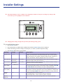
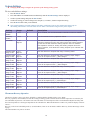
1
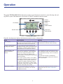
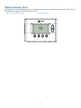
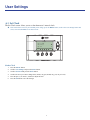
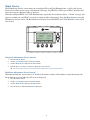
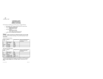
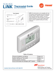
Thermostat Model TZEMT400BB32MAA User Guide Contents Product Specifications.............................................2 Operation...................................................................3 Thermostat Control Screen Function Control Buttons........................................................................ 4 Minimized Display Mode........................................... 5 Menu Map..................................................................6 User Settings............................................................7 Set Clock..................................................................... 7 Filter Service.............................................................. 8 Maint Service.............................................................. 9 Screen Timeout......................................................... 10 F/C Settings...............................................................11 Sensor Calibration.................................................... 12 Backlite/Display........................................................ 13 Usage Graph...........................................................14 ESM Setpoints........................................................15 ZWave Install...........................................................16 Inclusion.................................................................... 16 Exclusion................................................................... 16 Inclusion and Exclusion........................................... 16 Thermostat Info......................................................17 Installer Settings.....................................................18 System Settings........................................................ 19 Thermostat Recovery Operation.............................. 19 Mechanical Settings................................................. 20 Fan Cycler Settings.................................................. 20 Schedules................................................................21 Installation...............................................................24 Warranty..................................................................25 Index........................................................................26 1 Product Specifications Specification Description Product Model: TZEMT400BB32MAA Product: Thermostat for Heating and Cooling HVAC System control. Z-Wave™ RF communications enabled Thermostat Size: 5.7” wide x 4.0” height x 1.2” depth Display: Graphical LCD, 2.75” x 1.5”, 64x128-pixel Backlight: Yes, Blue/white, Controllable, on, off, timeout Contrast: Adjustable on screen Buttons: 6 Power: 24VAC from HVAC System HVAC System Type Compatible: Standard (gas/electric) or Heat Pump Multistage System Compatible: Standard HVAC Systems: 2 stage heating, 2-stage cooling Heat Pump Systems: 3 stage heating (2-compressor, 1 aux heat), 2-stage cooling Heat Pump change over valve: Selectable change over with cool or with heat Communications: Z-Wave™ RF 2 Operation The model TZEMT400BB32MAA thermostat provides typical thermostat control of a central heating and cooling HVAC system. This thermostat also features a Z-Wave™ module for remote control. Clock Display Ambient Temperature Display 11:15 PM Sys Off Run Filter MENU 72 AUTO MODE Setpoint Up/Down Buttons 77 H 74 C AUTO FAN RUN Dynamic Labels Temperature Setpoint Display Function Control Buttons Normally, the thermostat displays the thermostat control screen as shown above. Item Description Clock Display The current time is displayed in the upper See "User Settings", Set Clock for left corner of the main screen. The time will instructions to set time, date, and day. blink when the clock has not been set. Notes Function Control Buttons and Dynamic Labels As you press the function buttons and navigate through menus, the button labels will change. Dynamic button labels are displayed above or beside each button. Setpoint Display and Setpoint Up/Down Buttons The current heat and cool temperature setpoints are displayed. These setpoints may be set using the Z-Wave control system, by pressing the Setpoint Up/ Down buttons, or through the thermostat’s internal schedule Note: If the system mode is set to HEAT the setpoint Up/Down buttons change the heat setpoint. If the system mode is set to COOL the setpoint Up/Down buttons change the cool setpoint. In AUTO mode, the buttons change the heating or cooling setpoint of the last active mode. Temperature Display The thermostat displays the ambient temperature as sensed by the internal temperature sensor. 3 The setpoints will push each other if they are adjusted to within the minimum heat/ cool separation setting. This is normally 3 degrees. The internal schedule is disabled by default. See system setting H/C Delta for more information. The internal temperature sensor can be calibrated. See the Sensor Calibration section. Thermostat Function Control Buttons 11:15 PM Sys Off Run Filter MENU Menu Button 72 AUTO MODE System Mode Button AUTO FAN 77 H 74 C RUN Fan Mode Button Schedule Mode Button Button Description Menu Other thermostat menus can be accessed by pressing the MENU button. System Mode Used to change the system mode Off: System off Heating: Heating only on Cooling: Cooling only on Auto: Heating/Cooling on as necessary Fan Mode Used to change the fan mode Auto: Fan on when cooling/heating is necessary On: Fan constantly on Schedule Mode Used to change the schedule mode Hold: System maintains the current temperature setpoints. Schedules are disregarded. Run: Run the system schedule (or Z-Wave controlled schedule) Energy Saving Mode: Temperature setpoints in ESM Setpoints are maintained. See ESM Setpoints for more information. 4 Minimized Display Mode Optionally, you can set the thermostat to show only the temperature in minimized display mode. This mode can be enabled or disabled in the Users Settings screen. ÎÎ See Screen Timeout on page for more information. for more information. 72 5 Menu Map The menus are accessed by pressing the MENU button on the main screen. A. "User Settings" 1. Set Clock F. "Installer Settings" (hidden) 1. Display Lock 2. Filter Service 3. Maint. Service 4. Screen Timeout 5. F/C Settings 6. Sensor Callibration 7. Backlite/Display 2. System Settings a. Mechanical Settings 1. Type 2. Fan Type 3. C/O Type 4. 2nd Stage Heat 5. Aux Heat 6. 2nd Stage Cool b. Sched Enable c. Recovery Enable d. H/C Delta e. H Delta Stg1 ON f. H Delta Stg1 OFF g. H Delta Stg2 ON h. H Delta Stg2 OFF i. H Delta Stg3 ON j. H Delta Stg3 OFF k. C Delta Stg1 ON l. C Delta Stg1 OFF m. C Delta Stg2 ON n. C Delta Stg2 OFF B. "Usage Graph" C. "ESM Setpoints" D. "ZWave Install" E. "Thermostat Info" 3. Fan Cycler 4. Min Cool SP 5. Min Run Time 6. Min Off Time 7. T-Sense Match 8. Fan Cycler a. Fan ON Time b. Fan OFF Time 9. Restore Defaults G. "Schedules" (disabled by default) 1. Heat and Cool 2. Preset: Comfort 3. Preset: EnergyStar 4. Copy (small c on each schedule screen) 6 User Settings A.1 Set Clock The Set Clock screen allows you to set the thermostat’s internal clock. ÎÎ If the clock has been reset by an extended power outage, press the MENU button, scroll to the User Settings button and select, select the Set Clock screen and set clock. Set Clock + - Time 11: 15 AM Date 01/01 / 09 Day Thu Back Set Set the Clock 1. Press the MENU button. 2. Scroll to User Settings and press the Select button. 3. Scroll to Set Clock and press the Select button. 4. Scroll to the item you want to change (hour, minute, day part, month, day, year, day of week). 5. Press the plus (+) or minus (-) buttons to adjust the item. 6. Press the Set button to save the changes. 7 Filter Service The Filter Service screen will show the accumulated Filter Runtime hours as well as the Service Interval that will be used to trigger a Filter Message. Any type of HVAC operation that causes the HVAC system fan to run will cause the Filter Runtime value to increase. When the Runtime hours equals the Service Interval hours, a “Filter” message will appear to remind you to replace the media filter or service the air cleaner. Once the filter has been replaced, press the Reset button to reset the Filter Runtime value to zero. Filter Service Filter Runtime Service Interval Done 184 HRS 300 HRS + - Reset View/Reset Filter Runtime 1. Press the MENU button. 2. Scroll to User Settings and press the Select button. 3. Scroll to Filter Service and press the Select button. The Filter Runtime is displayed in hours. 4. To reset the Filter Runtime counter, press the Reset button. ÎÎ The Filter Runtime counter should be reset each time the filter is changed. Change the Filter Service Interval 1. Press the MENU button. 2. Scroll to User Settings and press the Select button. 3. Scroll to Filter Service and press the Select button. 4. Press the plus (+) or minus (-) buttons to adjust the service interval. ÎÎ The service interval can be set between 100 and 4000 hours in 100 hour increments. Factory default is 300 hours. Disable the Filter Service Interval When the filter service interval is disabled, the runtime counter will continue to count the runtime, but the filter service indicator will never be displayed. 1. Press the MENU button. 2. Scroll to User Settings and press the Select button. 3. Scroll to Filter Service and press the Select button. 4. Press the minus (-) button until Disabled is displayed 8 Maint Service The Maintenance Service screen shows the accumulated Heat and Cool Runtime hours as well as the Service Interval that will be used to trigger a Maintenance Message. Any HEAT or COOL type of HVAC operation will cause the respective Runtime values to increase. When the combined HEAT and COOL Runtime hours equals the Service Interval hours, a “Maint” message will appear to remind you your HVAC system may require periodic maintenance. Press the Menu button to enter the Maintenance Service screen. The Reset button can be pressed and the HEAT and COOL Runtime values will be reset to zero. Maintenance Service Heat Runtime Cool Runtime Service Interval Done + 200 HRS 300 HRS 3000HRS - Reset Change the Maintenance Service Interval 1. Press the MENU button. 2. Scroll to User Settings and press the Select button. 3. Scroll to Maint Service and press the Select button. 4. Press the plus (+) or minus (-) buttons to adjust the service interval. ÎÎ The service interval can be set between 200 and 4000 hours in 100 hour increments. Disable the Maintenance Service Interval When the maintenance service interval is disabled, the runtime counter will continue to count the runtime, but the maintenance service indicator will never be displayed. 1. Press the MENU button. 2. Scroll to User Settings and press the Select button. 3. Scroll to Maint Service and press the Select button. 4. Press the minus (-) button until Disabled is displayed 9 Screen Timeout This is the time before any screen reverts to the Minimized Screen (temperature display only), after you stop pushing buttons. Minimized Screen feature is disabled by setting this time to “0”. User Settings Set Clock Filter Service Maint Service Screen Timeout 0 Done Select Change the Screen Timeout 1. Press the MENU button. 2. Scroll to User Settings and press the Select button. 3. Scroll to Screen Timeout 4. Press the plus (+) or minus (-) buttons to adjust the time (in seconds). ÎÎ The screen time-out can be set between 0 and 120 seconds. Zero (0) is the default setting. When set to Zero (0), the minimized screen feature is disabled. Disable the Minimized Display 1. Press the MENU button. 2. Scroll to User Settings and press the Select button. 3. Scroll to Screen Timeout 4. Press the minus (-) button until zero (0) is displayed. 10 F/C Settings The F/C Settings screen is use to select the temperature display mode. Fahrenheit (F) or Celsius (C) are the two available modes. F/C Settings F/C Mode Done F + - Change the Temperature Mode 1. Press the MENU button. 2. Scroll to User Settings and press the Select button. 3. Scroll to F/C Settings and press the Select button. 4. Press the plus (+) or minus (-) buttons to change the temperature mode. Select F for Fahrenheit or C for Celsius. 11 Sensor Calibration The Sensor Calibration screen is used to change the temperature calibration of the internal temperature sensor. The temperature calibration can be changed by +/- 7 degrees. When the Sensor Calibration screen is selected, the current temperature calibration is displayed. In the example screen, the calibrated temperature is 77 and the number of degrees of offset being applied is 1. Sensor Calibration Internal (77) Done 1 + - Change the Sensor Calibration 1. Press the MENU button. 2. Scroll to User Settings and press the Select button. 3. Scroll to Sensor Calibration and press the Select button. 4. Press the plus (+) or minus (-) buttons to change the sensor calibration. ÎÎ After this screen is closed, it may take a few seconds for the temperature displayed on the main thermostat screen to update to the new temperature. 12 Backlite/Display The Backlite/Display screen is used to set the backlight time-out and contrast. Backlite Timeout is the time (in seconds) from the last button press to the backlight going out. The time-out can be set between zero (0) and one hundred and twenty (120) seconds. Thirty (30) is the default setting. When set to zero (0), the backlight will remain always on. Contrast sets the contrast level of the LCD display. The contrast can be set between zero (0) and twenty (20). Ten (10) is the default setting. If the display is too light, using a higher number. If dark lines appear in the display, use a lower number. Backlite/Display Backlite Timeout Contrast Done + 60 10 - Adjust the Backlight 1. Press the MENU button. 2. Scroll to User Settings and press the Select button. 3. Scroll to Backlite/Display and press the Select button. 4. Scroll to Backlite Timeout. 5. Press the plus (+) or minus (-) buttons to change the number of seconds. ÎÎ The backlight time-out can be set between 0 and 120 seconds. Thirty (30) is the default setting. When set to Zero (0), the backlight will remain always on. Adjust the Contrast 1. Press the MENU button. 2. Scroll to User Settings and press the Select button. 3. Scroll to Backlite/Display and press the Select button. 4. Scroll to Contrast. 5. Press the plus (+) or minus (-) buttons to change the contrast value. ÎÎ The contrast can be set between 0 and 20. Ten (10) is the default setting. 13 Usage Graph The Usage Graph shows daily heating and cooling runtime hours for a week. 20 15 10 Heating time (Hrs) 5 Sun Mon Tue Wed Thu Fri Sat Done Cool The button in the lower right corner will change depending on what is being displayed. When the heating time is displayed, the button will read Cool. When the cooling time is displayed, the button will read Heat. Press the Heat/Cool button to display the heating/cooling time. 14 ESM Setpoints Energy Saving Mode (ESM) Setpoints are the setpoints used when the Energy Saving Mode schedule is selected in the Schedule Mode screen. Energy Saving Mode Setpoings ESM - Heat ESM - Cool Done 80 + 65 - Adjust ESM Setpoints 1. Press the MENU button. 2. Scroll to ESM Setpoints and press the Select button. 3. To adjust the heat setpoint, scroll to ESM - Heat. Press the plus (+) or minus (-) buttons to adjust the setpoint. 4. To adjust the cool setpoint, scroll to ESM - Cool. Press the plus (+) or minus (-) buttons to adjust the setpoint. 15 ZWave Install Z-Wave™ controllers from various manufacturers may support the Z-Wave™ Thermostat General V2 Device class used by the Trane Z-Wave™ Thermostat. The following procedure will allow the thermostat to be added to a Z-Wave™ network. ÎÎ If you are using a controller that is not a Schlage bridge, consult the instructions that came with the controller to find out how to enroll a new device. Inclusion 1. Install a new, high-quality 9-volt battery into the bridge. 2. Hold the bridge within 6 feet (1.8 meters) of the thermostat throughout the entire inclusion process. ÎÎ After you begin the inclusion process, you have 30 seconds to complete the remainder of the steps. Study the steps below before beginning. 3. Press and release the plus (+) button on the bridge. 4. Press the MENU button on the thermostat. 5. Scroll to ZWave Install. Then press the Select button. 6. Press the Yes button. 7. Observe the lights on the bridge. The orange light will blink while enrollment is taking place. Enrollment is complete when the orange light becomes solid. Exclusion 1. Install a new, high-quality 9-volt battery into the bridge. 2. Hold the bridge within 6 feet (1.8 meters) of the thermostat throughout the entire exclusion process. ÎÎ Note: After you begin the enrollment process, you have 30 seconds to complete the remainder of the steps. Study the steps below before beginning. 3. Press and release the minus (-) button on the bridge. 4. Press the MENU button on the thermostat. 5. Scroll down to Z-Wave Install and press the Select button. 6. Press the Yes button to exclude the thermostat. 7. Observe the lights on the bridge. The orange light will blink while exclusion is taking place. Exclusion is complete when the orange light becomes solid. Inclusion and Exclusion with Other Controllers Inclusion or exclusion is started by putting the controller into add node or remove node state and performing the procedure outlined above. As part of the process, the thermostat sends a node information frame at normal power. Low power inclusion or low power exclusion is not possible. 16 Thermostat Info The Thermostat Info screen displays information about the thermostat and the system the thermostat controls. This information will be helpful if you need to contact customer support. Thermostat Info TZEMT400BB32 Ver: 01.00.10 ZVER: 02.00.9 ZNID: 004 ZHID: 01.07.37.bd System Type: Standard Fan Type: Gas Thermostat Info TZEMT400BB32 Ver: 01.00.10 ZVER: 02.00.9 ZNID: 004 ZHID: 01.07.37.bd System Type: Standard Fan Type: Gas Done Done Item Description TZEMT400BB32 Model Number Ver: 01.00.10 Firmware version ZVER: 02.00.9 Z-Wave version ZNID: 004 Z-Wave node ID ZHID: 01.07.37.bd Z-Wave Home ID System Type: Standard System type may be Standard or Heatpump Fan Type: Gas Fan type may be Gas or Elect (electric) ÎÎ This number may vary. ÎÎ This number may vary. ÎÎ This number may vary. ÎÎ This number may vary. 17 Installer Settings ÎÎ The Installer Settings screen is a hidden screen designed for installer use only. Do not change any settings in this screen unless you are a qualified service technician. Installer Settings Display Lock System Settings Max Heat SP Min Cool SP 90 60 Done - + N ÎÎ Changing these settings will affect the operation of the heating/cooling system. To view and edit these settings: 1. Press the MENU button. 2. Press and hold the two middle buttons simultaneously until the Installer Settings menu is displayed. 3. Scroll to the setting you want to change. Press the plus (+) or minus (-) button to adjust the setting. 4. Press the Done button when you are finished. Setting Range Default Description Display Lock Y or N N Locks or unlocks the thermostat buttons. When the buttons are locked, the main menu can still be accessed, but no menu options may be selected. The Installer Settings hidden button operation is always operational, allowing Display Lock to be turned off. Max Heat SP 55F to 90F (12C-32C) 90F (32C) Sets the maximum heating setpoint value. Will not ramp or accept setpoints higher than this maximum. Min Cool SP 60F to 99F (15C-37C) 60F (15C) Sets the minimum cooling setpoint value. Will not ramp or accept setpoints lower than this minimum. Minimum Run Time (MRT) 1- 9 Minutes 3 Sets the minimum run time before a heating/cooling cycle can turn off to prevent rapid cycling. Thermostat screen will display Cool ON or Heat ON while the minimum run time is being enforced. Minimum Off Time (MOT) 5-9 Minutes 5 Sets the minimum off time before another heating/cooling cycle can begin to provide compressor short cycle protection. Thermostat screen will display WAIT when minimum off time is being enforced. T-Sense Match 1-6 2 Sample rate of temperature sensor Low Sample Rate = Less sensitive (slower response) High Sample Rate = More sensitive (faster response) Restore Defaults n/a n/a Sets all of the thermostat settings back to the factory defaults. 18 System Settings ÎÎ Changing these settings will affect the operation of the heating/cooling system. To view and edit these settings: 1. Press the MENU button. 2. Press and hold the two middle buttons simultaneously until the Installer Settings menu is displayed. 3. Scroll to System Settings and press the Select button. 4. Scroll to the setting you want to change. Press the plus (+) or minus (-) button to adjust the setting. 5. Press the Done button when you are finished. ÎÎ Note on Delta Settings: The Delta T Setting is the delta, or difference between, the setpoint and current temp for determining when a heat or cool call comes on. The “delta” is the number of degrees away from setpoint. Setting Range Default Description Schedule Enable Y or N N When enabled, the local thermostats scheduler function is enabled. Recovery Enable Y or N N See Thermostat Recovery Operation below. H/C Delta 3 - 15 degrees 3 Sets the minimum separation between heating and cooling setpoints. Attempts to lower the cooling below the heating setpoint by this amount will PUSH the heating setpoint down to maintain this separation. Same for setting the heating setpoint above the cooling setpoint, it will PUSH the cooling setpoint up to maintain this separation. Heating Delta Stage 1 ON 1 to 8 degrees 1 Sets the delta from setpoint that stage 1 heating starts. Heating Delta Stage 1 OFF 0 to 8 degrees 0 Sets the delta from setpoint that stage 1 heating stops. Stage 1 turns off at setpoint minus (-) Delta Stage 1. Heating Delta Stage 2 ON 1 to 8 degrees 2 Sets the delta from setpoint that stage 2 heating starts. Heating Delta Stage 2 OFF 0 to 8 degrees 0 Sets the delta from setpoint that stage 2 heating stops. Stage 2 turns off at setpoint minus (-) Delta Stage 2. Heating Delta Stage 3 ON 1 to 8 degrees 3 Sets the delta from setpoint that stage 3 heating starts. Heating Delta Stage 3 OFF 0 to 8 degrees 0 Sets the delta from setpoint that stage 1 heating stops. Stage 3 turns off at setpoint minus (-) Delta Stage 3. Cooling Delta Stage 1 ON 1 to 8 degrees 1 Sets the delta from setpoint that stage 1 cooling starts. Cooling Delta Stage 1 OFF 0 to 8 degrees 0 Sets the delta from setpoint that stage 1 Cooling stops. Stage 1 turns off at setpoint plus (+) Delta Stage 1. Cooling Delta Stage 2 ON 1 to 8 degrees 2 Sets the delta from setpoint that stage 2 cooling starts. Cooling Delta Stage 2 OFF 0 to 8 degrees 0 Sets the delta from setpoint that stage 2 Cooling stops. Stage 2 turns off at setpoint plus (+) Delta Stage 2. Thermostat Recovery Operation The Recover feature is active only when “Schedule” is enabled and the schedule mode is set to “RUN” Recovery operation, when enabled, will start the cooling or heating system so that the desired comfort temperature is reached by the next scheduled set point time. The advance start time calculation is a learned process that is recalculated and adjusted each day until the room temperature is at the target temperature at the schedule time. When the thermostat is in Recovery mode the display will show “Recov”. Recovery works for all scheduled periods (1-4) and in HEAT, COOL or AUTO modes. While in Recovery the Aux-Heat stage will not engage. The maximum Recovery time is one hour. 19 Mechanical Settings ÎÎ Changing these settings will affect the operation of the heating/cooling system. To view and edit these settings: 1. Press the MENU button. 2. Press and hold the two middle buttons simultaneously until the Installer Settings menu is displayed. 3. Scroll to System Settings and press the Select button. 4. Scroll to Mechanical Settings and press the Select button. 5. Scroll to the setting you want to change. Press the plus (+) or minus (-) button to adjust the setting. 6. Press the Done button when you are finished. Setting Range Default Description Type Gas/Elec or Heatpump Gas/Elec Selects HVAC type, Gas/Electric or Heatpump Fan Type Gas or Elec Gas Selects the Fan type if system is Gas or Electric C/O Type w/Cool or w/ Heat w/Cool Set the Heat pump Changeover type 2nd Stage Heat Y or N N Enables the 2nd Stage Heat operation Aux Heat (HP) Y or N Y Enables the Auxiliary Heat operation. Typically the Aux Heat will be heat-strips in a Heatpump system 2nd Stage Cool Y or N N Enables the 2nd Stage Cool operation Fan Cycler Settings ÎÎ Changing these settings will affect the operation of the heating/cooling system. To view and edit these settings: 1. Press the MENU button. 2. Press and hold the two middle buttons simultaneously until the Installer Settings menu is displayed. 3. Scroll to Fan Cycler and press the Select button. 4. Scroll to the setting you want to change. Press the plus (+) or minus (-) button to adjust the setting. 5. Press the Done button when you are finished. Setting Range Default Description Fan ON Time 0-120 minutes 0 (=OFF) Fan OFF Time 10-120 minutes 10 The fan cycler function cycles the HVAC system fan for an ON period followed by an Off period continuously. Used to provide minimum air ventilation requirements. When the Fan ON time is set to a value greater than 0, an additional Cycler FAN mode is present when pressing the FAN button. 20 Schedules Scheduling is usually controlled by your Z-Wave system. See the instructions that came with your Z-Wave system for more information. However, scheduling may also be controlled by the thermostat. ÎÎ The Schedules menu is hidden by default, but may be enabled in the Installer Settings. See Enable/Disable the Schedules Menu on page 19 for more information. for more information. The thermostat has a 4 x 7 schedule, meaning the setpoints can be changed up to four times a day each day. Each day has a separate schedule. Schedules may be copied from one day to another day or group of days. See Copy a Day Schedule on page 23 for more information. for more information. Select Schedule Heat and Cool Preset:Confort Preset:Energy Star Done Select Enable/Disable the Schedules Menu Because the Schedules menu is disabled by default, you must first enable it before any scheduling can be done at the thermostat. If you want to use your Z-Wave system for scheduling, scheduling must be disabled in the thermostat. 1. Press the MENU button. 2. Press and hold the two middle buttons simultaneously until the Installer Settings menu is displayed. 3. Scroll to Systems Settings and press the Select button. 4. Scroll to Sched Enable and press the plus (+) button to enable scheduling or the minus (-) button to disable scheduling. ÎÎ When scheduling is enabled in the thermostat, a Y will be displayed next to Sched Enable. When scheduling is disabled in the thermostat, an N will be displayed next to Sched Enable. 21 Load a Preset Schedule There are two possible schedules that may be loaded: Preset Comfort and Preset Energy Star. These schedules may not be changed. When a schedule is loaded, it changes the current Heat and Cool schedule settings. You can then edit the Heat and Cool schedule, if necessary. ÎÎ Selecting Preset Comfort or Preset Energy Star schedules will overwrite the current Heat and Cool schedule. 1. Press the MENU button. 2. Scroll to Schedules and press the Select button. 3. Scroll to the schedule you want to load and press the Select button. 4. Press the Yes button. Monday Schedule Time Heat Cool Wake 06 :00 A 70 78 Day 08 :00 A 70 78 Eve 04 :00 P 70 78 Sleep 10 : 00 P 66 81 Done + c Select Preset Schedule Description Preset: Comfort This is a preset schedule with mild setbacks, designed to maintain a comfortable temperature. Preset: Energy Star This is a preset schedule with deeper setbacks, designed to conserve energy. View the Current Schedule 1. Press the MENU button. 2. Scroll to Schedules and press the Select button. 3. Scroll to Heat and Cool and press the Select button. 4. The schedule for the current day will be displayed. To view other days, press the Next button. Set a Heat and Cool Schedule 1. Press the MENU button. 2. Scroll to Schedules and press the Select button. 3. Scroll to Heat and Cool and press the Select button. 4. The schedule for the current day will be displayed. To view other days, press the Next button 5. To change a setting (hour, minute, day part, heat setpoint or cool setpoint), scroll to that setting using the left () or right () arrow buttons. Then press the plus (+) or minus (-) buttons as necessary. ÎÎ Continue pressing the left () or right () arrow buttons to move to the next line. 22 Copy a Day Schedule 1. Press the MENU button. 2. Scroll to Schedules and press the Select button. 3. Scroll to Heat and Cool and press the Select button. 4. The day of the week is displayed at the top of the screen. Press the Next button until the day you want to copy is displayed. 5. Highlight the small c in the lower right corner by pressing the left arrow () button once. The Next button will change to Copy. 6. Press the Copy button. 7. For each day to which you want to copy the day schedule, change the N (no) to Y (yes). Use the left () or right () arrow buttons to scroll to the day and the use the Yes or No buttons on the side of the screen. 8. Press the Copy button. 23 Installation For complete installation instructions, browse to part2.schlage.com and download Trane Thermostat Installation Instructions. 24 Warranty Trane Remote Energy Management Thermostat Limited One (1)-Year Electronics and Mechanical Warranty U.S.A. and Canada Only Subject to the terms and conditions of this Limited One (1)-Year Electronics and Mechanical Warranty, Trane warrants that, if within one (1) year from Original Date of Purchase, the Purchased Product fails due to defect in manufacture, material or workmanship, Trane will provide a replacement for the Purchased Product or refund the Original Purchase Price, at its sole option, to the Original Purchaser occupying the premises in which the Purchased Product was originally installed. This warranty applies to the Original Purchaser only and is nontransferable. The one (1)-year limited warranty period begins from Original Date of Purchase, confirmed by sales receipt or other dated proof of purchase. Exclusions: The following costs, expenses and damages are not covered by the terms and conditions of this One(1)-Year Limited Electronics and Mechanical Warranty: (i) labor and costs including, but not limited to, original initial installation, removal and reinstallation of Purchased Product; (ii) shipping and freight expenses for any required return of Purchased Product; (iii) failures, defects, or damages (including, but not limited to, any security failure or loss of data) caused by any third party product, service, or system connected or used in conjunction with the Purchased Product; and (iv) any other incidental, consequential, indirect, special and/or punitive damages, whether based on contract, warranty (express or implied), tort (including, but not limited to, strict liability or negligence), patent infringement, or otherwise, even if advised of the possibility of such damages. Additionally, this limited warranty does not cover scratches, abrasions, or deterioration due to the use of paints, solvents or other chemicals. Further, the terms and conditions of this One (1)-Year Limited Electronics and Mechanical Warranty do not apply to Purchased Product when: (1) used in common area applications (2) used for purposes for which it was not designed or intended; (3) subjected to alteration, modification, abuse, misuse, negligence or accident, improper storage, improper installation or maintenance or operation or unauthorized repair; (4) used in violation of written instructions provided for Purchased Product; (5) subjected to improper temperature, humidity or other environmental conditions; or (6) damaged as a result of acts of God. This One (1)-Year Limited Electronics and Mechanical Warranty is the only express warranty Trane makes on this product. THE DURATION OF ANY IMPLIED WARRANTIES, INCLUDING THE WARRANTIES OF MERCHANTABILITY AND FITNESS FOR A PARTICULAR PURPOSE, IS HEREBY LIMITED TO THE ONE-YEAR DURATION OF THIS WARRANTY. IF THIS PURCHASED PRODUCT IS CONSIDERED A CONSUMER PRODUCT, SOME STATES DO NOT ALLOW THE EXCLUSION OR LIMITATION OF INCIDENTAL OR CONSEQUENTIAL DAMAGES, SO THIS LIMITATION MAY NOT APPLY TO YOU. REFER TO YOUR LOCAL LAWS FOR YOUR SPECIFIC RIGHTS UNDER THIS WARRANTY. Additional items: Trane does not authorize any person to create for it any obligation or liability in connection with the Purchased Product. Trane’s maximum liability hereunder is limited to the Original Purchase Price of the Purchased Product. No action arising out of any claimed breach of this warranty by Trane may be brought by the Original Purchaser more than one (1) year after the cause of action has arisen. If you have a claim under this warranty, please return the Purchased Product to place of purchase for replacement or refund of the Original Purchase Price in exchange for the return of the Purchased Product, including sales receipt or other dated proof of purchase. Contact Schlage Customer Service at 877-288-7707 in U.S.A. and Canada for assistance with set-up and installation, or questions regarding your warranty claim. 25 Index Symbols 2nd Stage Cool 20 2nd Stage Heat 20 A Adjust Backlight 13 Contrast 13 ESM Setpoints 15 Aux Heat (HP) 20 B Backlight Adjust 13 Backlite 13 Backlite/Display 13 Button Menu 4 Buttons Function Control 4 Setpoint 3 C Calibration Sensor 12 Celsius 11 Change Filter Service Interval 8 Maintenance Service Interval 9 Screen Timeout 10 Sensor Calibration 12 Temperature Mode 11 Clock Display 3 Set 7 Comfort Schedule 22 Contrast 13 Adjust 13 Cooling Delta Stage 1 OFF 19 Cooling Delta Stage 1 ON 19 Cooling Delta Stage 2 OFF 19 Cooling Delta Stage 2 ON 19 Copy Schedule 23 C/O Type 20 D Defaults Restore 18 Disable Filter Service Interval 8 Maintenance Service Interval 9 Minimized Display 10 Schedules 21 Display Clock 3 Setpoint 3 Temperature 3 Display Lock 18 Dynamic Labels 3 E Enable Recovery 19 Schedule 19 Schedules 21 Energy Star Schedule 22 ESM (Energy Savings Mode) Setpoints 15 Adjust 15 Exclusion 16 F Fahrenheit 11 Fan Mode 4 Fan Cycler Settings 20 Fan OFF Time 20 Fan ON Time 20 Fan Type 20 F/C Settings 11 Filter Service 8 View/Reset Filter Runtime 8 Filter Service Interval Change 8 Disable 8 Function Control Buttons 4 Thermostat Control Screen 3 H H/C Delta 19 Heating Delta Stage 1 OFF 19 Heating Delta Stage 1 ON 19 Heating Delta Stage 2 OFF 19 Heating Delta Stage 2 ON 19 Heating Delta Stage 3 OFF 19 Heating Delta Stage 3 ON 19 I Inclusion 16 Installation 24 Installer Settings 18 L Labels Dynamic 3 Load Preset Schedule 22 M Maintenance Service 9 Maintenance Service Interval Change 9 Disable 9 Maint Service 9 Max Heat SP 18 Mechanical Settings 20 26 Menu Button 4 Menu Map 6 Min Cool SP 18 Minimized Display 5 Disable 10 Mode 5 Minimum Off Time 18 Minimum Run Time 18 Mode Fan 4 Minimized Display 5 Schedule 4 System 4 Temperature 11 MOT 18 MRT 18 O Operation 3 P Preset Schedule Load 22 R Recovery Enable 19 Restore Defaults 18 S Schedule Comfort 22 Copy 23 Energy Star 22 Load Preset 22 Mode 4 Preset 22 Set 22 View 22 Schedule Enable 19 Schedules 21 Disable 21 Enable 21 Screen Timeout 10 Change 10 Sensor Calibration 12 Change 12 Service Maintenance 9 Set Clock 7 Schedule 22 Setpoints Display 3 ESM (Energy Savings Mode) 15 Up/Down Buttons 3 Settings Fan Cycler 20 Installer 18 Mechanical 20 User 7 Specifications 2 System Mode 4 System Settings 19 T T-Sense Match 18 Temperature Display 3 Mode 11 Temperature Mode Change 11 Thermostat control screen 3 Thermostat Control Screen Function Control Buttons 4 Thermostat Info 17 Type 20 U Usage Graph 14 User Settings 7 V View Filter Runtime 8 Schedule 22 W Warranty 25 Z Z-Wave Exclusion 16 Inclusion 16 ZWave Install 16 27 FCC Notice FCC ID WIBTZW008 INFORMATION TO USER This device complies with Part 15 of the FCC Rules. Operation is subject to the following two conditions: (1) This device may not cause harmful interference, and (2) This device must accept any interference received, including interference that may cause undesired operation. This equipment has been tested and found to comply with the limits for Class B Digital Device, pursuant to Part 15 of the FCC Rules. These limits are designed to provide reasonable protection against harmful interference in a residential installation. This equipment generates and can radiate radio frequency energy and, if not installed and used in accordance with the instructions, may cause harmful interference to radio communications. However, there is no guarantee that interference will not occur in a particular installation. If this equipment does cause harmful interference to radio or television reception, which can be determined by turning the equipment off and on, the user is encouraged to try to correct the interference by one or more of the following measures. • • • • Reorient or relocate the receiving antenna Increase the separation between the equipment and receiver Connect the equipment into an outlet on a circuit different from that to which the receiver is connected Consult the dealer or an experienced radio/TV technician for help Any changes or modifications not expressly approved by the party responsible for compliance could void the user’s authority to operate the equipment. IC Notice IC 9374A-TZ45 This device complies with Industry Canada license-exempt RSS standard(s). Operation is subject to the following two conditions: (1) this device may not cause interference, and (2) this device must accept any interference, including interference that may cause undesired operation of the device. Le présent appareil est conforme aux CNR d'Industrie Canada applicables aux appareils radio exempts de licence. L'exploitation est autorisée aux deux conditions suivantes : (1) l'appareil ne doit pas produire de brouillage, et (2) l'utilisateur de l'appareil doit accepter tout brouillage radioélectrique subi, même si le brouillage est susceptible d'en compromettre le fonctionnement. ©2011 Schlage Lock Company TZEMT400B User Guide Rev. 06/11-b 32-5082-01 28