1
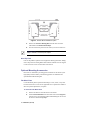
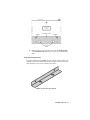
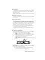
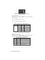
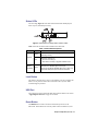
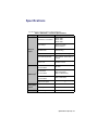
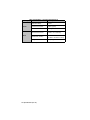
SHC-9642 SDI to HDMI Converter User Manual SHC-9642 User Manual • Ross Part Number: 9642DR-004-02 • Release Date: August 9, 2012. The information contained in this manual is subject to change without notice or obligation. Copyright © 2012 Ross Video Limited. All rights reserved. Contents of this publication may not be reproduced in any form without the written permission of Ross Video Limited. Reproduction or reverse engineering of copyrighted software is prohibited. Patents This product is protected by the following US Patents: 4,205,346; 5,115,314; 5,280,346; 5,561,404; 7,034,886; 7,508,455; 7,602,446; 7,834,886; 7,914,332. This product is protected by the following Canadian Patents: 2039277; 1237518; 1127289. Other patents pending. Notice The material in this manual is furnished for informational use only. It is subject to change without notice and should not be construed as commitment by Ross Video Limited. Ross Video Limited assumes no responsibility or liability for errors or inaccuracies that may appear in this manual. Trademarks • • 1 is a registered trademark of Ross Video Limited. is a trademark of Ross Video Limited. • Ross, ROSS, ROSS®, and MLE are registered trademarks of Ross Video Limited. • SAM-BA® is a registered trademark of Atmel® Corporation or its subsidiaries, in the US and/or other countries. • VELCRO® is a registered trademark of Velcro Industries B.V. • All other product names and any registered and unregistered trademarks mentioned in this manual are used for identification purposes only and remain the exclusive property of their respective owners. Important Regulatory and Safety Notices to Service Personnel Before using this product and any associated equipment, refer to the “Important Safety Instructions” listed below to avoid personnel injury and to prevent product damage. Product may require specific equipment, and/or installation procedures to be carried out to satisfy certain regulatory compliance requirements. Notices have been included in this publication to call attention to these specific requirements. Symbol Meanings Protective Earth — This symbol identifies a Protective Earth (PE) terminal, which is provided for connection of the supply system’s protective earth (green or green/yellow) conductor. This symbol on the equipment refers you to important operating and maintenance (servicing) instructions within the Product Manual Documentation. Failure to heed this information may present a major risk of damage or injury to persons or equipment. Warning — The symbol with the word “Warning” within the equipment manual indicates a potentially hazardous situation which, if not avoided, could result in death or serious injury. Caution — The symbol with the word “Caution” within the equipment manual indicates a potentially hazardous situation which, if not avoided, may result in minor or moderate injury. It may also be used to alert against unsafe practices. Warning Hazardous Voltages — This symbol is intended to alert the user to the presence of uninsulated “dangerous voltage” within the product enclosure that may be of sufficient magnitude to constitute a risk of shock to persons. ESD Susceptibility — This symbol is used to alert the user that an electrical or electronic device or assembly is susceptible to damage from an ESD event. 2 Important Safety Instructions 1. Warning – Read these instructions. 2. Keep these instructions. 3. Heed all warnings. 4. Follow all instructions. 5. The safe operation of this product requires that a protective earth connection be provided. A grounding conductor in the equipment's supply cord provides this protective earth. To reduce the risk of electrical shock to the operator and service personnel, this ground conductor must be connected to an earthed ground. 6. Do not defeat the safety purpose of the grounding-type plug. A grounding type plug has two blades and a third grounding prong. The third prong is provided for your safety. If the provided plug does not fit in to your outlet, consult an electrician for replacement of the obsolete outlet. Protect the power cord from being walked on or pinching particularly at plugs, convenience receptacles, and point where they exit from the apparatus. 7. Warning – Indoor Use: WARNING: To reduce the risk of fire or electric shock, do not expose this apparatus to rain or moisture. 8. Do not block ventilation openings. Install in accordance with manufacturer's instructions. 9. Do not install near heat sources such as radiators, heat registers, stoves, or other apparatus (including amplifiers) that produce heat. 10. Do not use this apparatus near water. 11. Only use attachments/accessories specified by the manufacturer. 12. Unplug this apparatus during lightning storms or when unused for long periods of time. 13. Clean only with a dry cloth. 14. To avoid electrical shock, disconnect the A/C power cord before any servicing. 15. Refer all servicing to qualified personnel. Servicing is required when the apparatus has been damaged in any way, such as power-supply cord or plug damage, liquid has been spilled or objects have fallen into the apparatus, the apparatus has been exposed to rain or moisture, does not operate normally, or has been dropped. 3 EMC Notices United States of America FCC Part 15 This equipment has been tested and found to comply with the limits for a class A Digital device, pursuant to part 15 of the FCC Rules. These limits are designed to provide reasonable protection against harmful interference when the equipment is operated in a commercial environment. This equipment generates, uses, and can radiate radio frequency energy and, if not installed and used in accordance with the instruction manual, may cause harmful interference to radio communications. Operation of this equipment in a residential area is likely to cause harmful interference in which case the user will be required to correct the interference at his own expense. Notice — Changes or modifications to this equipment not expressly approved by Ross Video Limited could void the user’s authority to operate this equipment. CANADA This Class “A” digital apparatus complies with Canadian ICES-003. Cet appariel numerique de la classe “A” est conforme a la norme NMB-003 du Canada. EUROPE This equipment is in compliance with the essential requirements and other relevant provisions of CE Directive 93/68/EEC. INTERNATIONAL This equipment has been tested to CISPR 22:1997 along with amendments A1:2000 and A2:2002, and found to comply with the limits for a Class A Digital device. Notice — This is a Class A product. In domestic environments, this product may cause radio interference, in which case the user may have to take adequate measures. Maintenance/User Serviceable Parts Routine maintenance to this GearLite product is not required. This product contains no user serviceable parts. If the module does not appear to be working properly, please contact Technical Support using the numbers listed under the 4 “Contact Us” section on the last page of this manual. All GearLite products are covered by a generous 3-year warranty and will be repaired without charge for materials or labor within this period. See the “Warranty and Repair Policy” section in this manual for details. Environmental Information The equipment that you purchased required the extraction and use of natural resources for its production. It may contain hazardous substances that could impact health and the environment. To avoid the potential release of those substances into the environment and to diminish the need for the extraction of natural resources, Ross Video encourages you to use the appropriate take-back systems. These systems will reuse or recycle most of the materials from your end-of-life equipment in an environmentally friendly and health conscious manner. The crossed-out wheeled bin symbol invites you to use these systems. If you need more information on the collection, reuse, and recycling systems, please contact your local or regional waste administration. You can also contact Ross Video for more information on the environmental performances of our products. 5 Introduction Overview The SHC-9642 SDI to HDMI Converter is a high-quality signal conversion solution within the family of GearLite compact, self-contained modular products. The SHC-9642 is the ideal solution for converting an SDI input signal to output an HDMI Type A signal to another device. A universal power adaptor and line cord, suitable for the country of use, is supplied with each module. Various mounting options are included that enable a wide range of installation choices. Simplified Block Diagram SDI OUT SDI IN EQ RECLOCKER HDMI OUT SDI TO HDMI AUDIO DECODE / SELECT AUDIO RIGHT AUDIO LEFT Figure 1 Simplified Block Diagram of SHC-9642 Functions Features The SHC-9642 SDI to HDMI Converter includes the following features: • • • • • • • • • • • • • One HDMI Type A connector One BNC connector for an SDI input One BNC connector for a reclocked SDI output One USB port for upgrades Two RCA connectors for analog audio output Supports major SDI formats up to 1080p 60Hz Automatically applies correct color spaces for SD, HD, and 3G video formats User-selectable RGB and YCbCr output User-selectable HDMI or DVI formatting, allowing use with a wide variety of monitors Power and SDI Input Status indicator LEDs Small brick form factor 5V universal adapter with locking DC connector 3-year warranty Introduction (Iss. 02) • 6 Installation Static Discharge Whenever handling the SHC-9642 SDI to HDMI Converter and other related equipment, please observe all static discharge precautions as described in the following note: ESD Susceptibility — Static discharge can cause serious damage to sensitive semiconductor devices. Avoid handling circuit boards in high static environments, such as carpeted areas, and when wearing synthetic fiber clothing. Always exercise proper grounding precautions when working on circuit boards and related equipment. Unpacking Unpack each SHC-9642 you received from the shipping container and ensure that all items are included. If any items are missing or damaged, contact your sales representative or Ross Video directly. Mounting and Installation The SHC-9642 SDI to HDMI Converter can be mounted in any convenient location. However, to ensure long life for this product, observe the following precautions and operating requirements: • • Maintain an ambient temperature of 0°C to 40°C (32°F to 104°F). Allow for air circulation around the chassis for convectional cooling. Many different mounting positions are possible with the included mounting hardware. Some installation options are permanent and require careful consideration of the final positioning before installation. Please note that in some mounting locations, the power adaptor must be affixed in a similar manner as the chassis. Other possible options include the use of adhesive magnetic sheets (not included) affixed to the chassis and the power adaptor, for removable mounting on metal cabinets etc. Cable ties may be necessary in some applications to relieve strain on the mounting hardware and the connectors. 7 • Installation (Iss. 02) Tie-wraps The SHC-9642 provides two convenient slots, one on each side of the chassis, that allow the chassis to be attached to a suitable surface using a tie-wrap. (Figure 2) Figure 2 Tie-wrap Slots Surface Mount Strips The included VELCRO® brand surface mount strips allow the GearLite module and power supply to be affixed to a permanent location during use and easily removed for adjustments. Carefully consider the installation location before proceeding; the adhesive is very aggressive and is not easily removed. The adhesive will cure fully in 24 hours. To install the Surface Mount Strips 1. Remove the Protective Backing Film from the adhesive on the bottom of the two VELCRO® brand Surface Mount Strips. 2. Adhere the Surface Mount Strips to the bottom side of the chassis. (Figure 3) Installation (Iss. 02) • 8 Figure 3 Surface Mount Installation Option 3. Remove the Protective Backing Film from the other side of the VELCRO® brand Surface Mount Strips. 4. Press the chassis into position on the surface you want to mount it to. Operating Tip — An additional VELCRO® brand Surface Mount Strip is available to mount the power adapter. Non-Slip Pads Four non-slip adhesive pads have been supplied for desktop placements. Simply remove the protective backing film from the adhesive and affix one non-slip pad to each of the four corners on the bottom of the chassis. Optional Mounting Accessories Ross Video is committed to providing practical solutions for the needs of your high-quality broadcast facility. The following products are included in the optional MNT-9642 Mounting Kit. Flat Metal Plate Use the flat metal plate for permanent mounting to a rack, a desk, or any other location where bolts or screws can be applied. Be sure to position the module to allow for operator adjustments, if required. To install the Flat Metal Plate 1. Remove the 2 screws from the bottom of the chassis. 2. Install the Flat Metal Plate onto the bottom of the chassis (Figure 4) using the screws provided in the MNT-9642 Mounting Kit. Do not use the screws removed during Step 1. 9 • Installation (Iss. 02) Figure 4 Flat Metal Plate Installation Option 3. Install the chassis in the desired location using the Mounting Holes on the Flat Metal Plate. Mounting screws are not provided by Ross Video. Angle Mounting Bracket The Angle Mounting Bracket (Figure 5) allows a single GearLite module to be installed in positions not possible with the flat metal plate. The bracket has a 90° angle. Mounting screws are not provided by Ross Video. Figure 5 Angle Mounting Bracket Installation (Iss. 02) • 10 Setup and Operation Power Adapter and Supply Connect the PS-9000 power adaptor to the power supply connector. The PS-9000 provides regulated +5V DC (5%) @ up to 2A. The DC power cord has a locking connector that securely fastens into the power supply DC jack on the SHC-9642. The SHC-9642 has a standard miniature power jack (center pin positive). Refer to the section “Important Regulatory and Safety Notices to Service Personnel” at the front of this manual for details. If using an adaptor other than the PS-9000, ensure that: • • • the polarity is correct the voltage is +5V DC regulated to 5% sufficient current for the SHC-9642 is supplied Caution — Use of improper adaptors may damage the SHC-9642 and will void the warranty. Cable Connections Overview There are five connections to the SHC-9642: • • • • • An HDMI Type A output A BNC jack for the SDI input A BNC jack for the SDI output Two RCA connections for Analog Audio output A power supply connection to the GearLite PS-9000 power adaptor ANLG AUDIO LEFT OUT ANLG AUDIO RIGHT OUT POWER SUPPLY SDI IN SDI OUT HDMI OUT SDI IN LOCKED LED Figure 6 SHC-9642 Cable Connections HDMI Connection Connect the HDMI output cable to the SHC-9642 according to the designations indicated on the chassis label and Figure 6. 11 • Setup and Operation (Iss. 02) SDI Connections Connect the SDI source to the SDI IN BNC. If the input source is successfully detected, the SDI LOCKED LED will light solid green. Refer to Figure 6 for BNC and LED locations. If desired, connect the SDI OUT. It is not necessary to terminate unused outputs. Analog Audio Connections Optionally, connect the two analog audio RCA outputs to a line-level amplifier or receiver input. Notes on Video Formats The SHC-9642 produces exactly the same video format at its HDMI output as you apply to its SDI input. It performs no scaling or other modification of the image. If there is no image displayed on your monitor, or the image is unstable, the most likely cause is that the monitor is incapable of displaying the video format that is present in your SDI signal. The display may also have an unexpected appearance, or no image at all, if the SHC-9642 has been set for YCbCr and the monitor does not support this mode. The formats that the SHC-9642 can convert are listed in Table 4 on page 18. DIP Switch Configuration The SHC-9642 includes four DIP switches located on the front edge. (Figure 7) These switches are used to configure the SHC-9642 as follows: • • • SW4 selects RGB or YCbCr format for the HDMI output SW3 selects HDMI or DVI formatting in the HDMI output. The DVI setting enables the SHC-9642 to be connected, using a passive HDMI-DVI converter, to a DVI monitor. SW2 and SW1 specify which audio channels are routed to the analog outputs Figure 7 DIP Switch Location on the SHC-9642 SW1 to SW4 are set in the UP () position by default as illustrated in Figure 8. This configures the SHC-9642 as follows: • • Specifies the HDMI output as RGB 4:4:4, with HDMI formatting Analog audio Channels 1-2 are routed to the outputs Setup and Operation (Iss. 02) • 12 1 2 3 4 Figure 8 DIP Switches — Set in the UP Position Audio Configuration Table 1 outlines how to set SW1, and SW2 for audio output and the following conventions are used: Set the DIP switch in the UP position Set the DIP Switch in the DOWN position Table 1 Audio Config — DIP Switch Positions HDMI Audio SW1 SW2 Analog Audio Out CH 1-8 * * CH 1, 2 CH 3, 4 CH 5, 6 CH 7, 8 *= Default setting HDMI Output Configuration Table 2 outlines how to set SW3 and SW4 to specify the HDMI output mode. Note that DVI settings require a passive HDMI-DVI adaptor. Table 2 HDMI Output Configuration SW3 SW4 HDMI Output * * RGB 4:4:4 HDMI format YCbCr 4:4:4 HDMI format RGB 4:4:4 DVI format RGB 4:4:4 DVI format *= Default setting 13 • Setup and Operation (Iss. 02) Status LEDs The front edge (Figure 9) of the SHC-9642 includes LEDs that display the status of power, and SDI input activity. Figure 9 SHC-9642 Front Edge Status Indicator LEDs Table 3 describes the status LEDs available on the SHC-9642. Table 3 Status LED Descriptions LED Color Function Green POWER When this LED is continually lit green, the SHC-9642 is operating correctly. When this LED is lit red: Red • an error is occurring or • SHC-9642 is currently in Upgrade Software mode SDI IN LOCKED Green LED is continually lit when the SHC-9642 determines that there is a valid SDI signal on the input. There are two SDI IN LOCKED LEDs (one on each end of the SHC-9642) that report the same information. Load Button This button is used for factory service in the unlikely event of a complete unit failure. Do not press this button unless instructed to do so by Ross Video Technical Support personnel. USB Port The USB port is used to upgrade the SHC-9642 software. Refer to the section “Upgrading the Software” on page 15 for details. Reset Button The Reset button is used to reboot the internal microprocessor in the SHC-9642. This should not be necessary under normal circumstances, but is Setup and Operation (Iss. 02) • 14 available if the SHC-9642 no longer appears to respond to changing DIP Switch settings or input changes. Similar results can also be achieved by cycling power to the SHC-9642. Upgrading the Software The SHC-9642 can be upgraded in the field via the USB port connected to a PC. During the upgrade, your SHC-9642 is taken temporarily offline. There are five steps to upgrading your SHC-9642 software: 1. Install the GearLite Upgrade Utility on your PC. 2. Reset the SHC-9642. 3. Connect the SHC-9642 to your PC. 4. Run the GearLite Upgrade Utility. 5. Re-boot the SHC-9642. Requirements To upgrade your SHC-9642 software, you require the following items: • • • • GearLite Upgrade Utility *.bin file for the SHC-9642 Mini-B USB Interface cable PC with Microsoft® Windows XP® or Microsoft® Windows 7® OS Install the GearLite Upgrade Utility Software 1. Contact Ross Video Technical Support for the latest GearLite Upgrade Utility. The *.bin file for your SHC-9642 is included with the GearLite Upgrade Utility. 2. Copy the GearLite Upgrade Utility to the C:\ root directory of your PC. 3. Navigate to the run.bat file on your PC. 4. Double-click the run.bat file to launch the GearLite Upgrade Utility. Reset the SHC-9642 1. Ensure that your SHC-9642 is currently not in use within your workflow. 2. Press and hold the LOAD button on the SHC-9642. Refer to Figure 9 for button locations. 3. Press the Reset button. 4. Release the LOAD button. 15 • Setup and Operation (Iss. 02) 5. Wait 3 seconds. 6. Press the Reset button. The POWER LED is lit red. Connect the SHC-9642 to your PC 1. Locate the USB port on the SHC-9642. Refer to Figure 9 for port location. 2. Connect one end of a Mini-B USB interface cable to the USB port on the SHC-9642. 3. Connect the other end of the Mini-B interface cable to the USB port on the PC with the GearLite Upgrade Utility installed. The Found New Hardware Wizard window displays. 4. Follow the on-screen instructions on the Found New Hardware Wizard to install the driver for the SHC-9642 on your PC. • 5. If you are running Microsoft® Windows XP®, the Hardware Installation dialog may display. Click Continue Anyway to continue the driver installation on your PC. Ensure that the driver is correctly installed and that the SHC-9642 is recognized as connected to the USB port of your PC. Run the GearLite Upgrade Utility Software 1. If you do not already have the GearLite Upgrade Utility running, launch it by double-clicking the run.bat file. 2. From the GearLite Upgrade Utility tool bar, select File > Select. 3. Select Choose a File. 4. Navigate to the *.bin file for your SHC-9642. 5. Click Update. 6. Click OK in the dialog. The upgrade process can take up to a minute. 7. Wait for the pop-up message “The upgrade has been successfully sent to the SHC-9642” to display in the GearLite Upgrade Utility window to confirm that the upgrade process is complete. Re-boot the SHC-9642 1. Disconnect the SHC-9642 from your PC. 2. Press the Reset button on the SHC-9642. Setup and Operation (Iss. 02) • 16 Verify the Upgrade 1. Verify that the POWER LED is lit green. If this LED is lit red, the upgrade has failed and you must repeat the upgrade process. 2. Disconnect the DC power source to the SHC-9642. 3. Connect an HDMI or DVI monitor to the SHC-9642 via the HDMI port. 4. Re-connect the DC power source to the SHC-9642. 5. Ensure that: • the POWER LED is lit green • the SHC-9642 successfully converts the SDI input to HDMI output. 17 • Setup and Operation (Iss. 02) Specifications Specifications are subject to change without notification. Table 4 SHC-9642 — Technical Specifications Category Parameter Specification SDI Input/ Output HDMI Outputa Analog Audio Outputs USB Port Standards Accommodated SMPTE 259M SMPTE 292M SMPTE 424M Input Voltage 800mV p-p (typical) 950mV maximum SDI Data Rate 270MHz/1.485GHz/2.97GHz (auto selecting) Impedance 75ohms (input terminating) Input Cable Equalization >80m of Belden 1694A cable to 2.97GHz Return Loss >15dB to 1.48GHz >10dB to 2.97GHz SD Standards Accommodated 525i, 625i HD Standards Accommodated 720p (50/59.94/60) 1080i (50/59.94/60) 1080p (23.98/24/25/30) 3G Standards Accommodated 1080p (50/59.94/60) Output Color Space RGB 4:4:4 or YCbCr 4:4:4 Output Level -10dBV, unbalanced Sampling Rate 48KHz Connector Type Mini-B, receptacle Specifications (Iss. 02) • 18 Table 4 SHC-9642 — Technical Specifications Category Parameter Specification Power Other Required Voltage +5v DC Current Consumption 500mA (typical) Total Power 2.5W typical Thermal Environment 0°C to 40°C (32°F to 104°F) ambient, non-condensing Dimensions (LxWxH) 4.0” x 5.65” x 1.25” (10.16cm x 14.35cm x 3.18cm) Weight 15oz (425g) a.Standard set by SDI input. 19 • Specifications (Iss. 02) Appendix A. This appendix provides software license information for your SHC-9642. This product includes software components which are individually licensed under the licenses included in this appendix. Atmel® Microcontroller Software License Copyright (c) 2011, Atmel Corporation All rights reserved. Redistribution and use in source and binary forms, with or without modification, are permitted provided that the following conditions are met: • Redistributions of source code must retain the above copyright notice, this list of conditions and the disclaimer below. Atmel’s name may not be used to endorse or promote products derived from this software without specific prior written permission. DISCLAIMER: THIS SOFTWARE IS PROVIDED BY ATMEL "AS IS" AND ANY EXPRESS OR IMPLIED WARRANTIES, INCLUDING, BUT NOT LIMITED TO, THE IMPLIED WARRANTIES OF MERCHANTABILITY, FITNESS FOR A PARTICULAR PURPOSE AND NON-INFRINGEMENT ARE DISCLAIMED. IN NO EVENT SHALL ATMEL BE LIABLE FOR ANY DIRECT, INDIRECT, INCIDENTAL, SPECIAL, EXEMPLARY, OR CONSEQUENTIAL DAMAGES (INCLUDING, BUT NOT LIMITED TO, PROCUREMENT OF SUBSTITUTE GOODS OR SERVICE; LOSS OF USE, DATA, OR PROFITS; OR BUSINESS INTERRUPTION) HOWEVER CAUSED AND ON ANY THEORY OF LIABILITY, WHETHER IN CONTRACT, STRICT LIABILITY, OR TORT (INCLUDING NEGLIGENCE OR OTHERWISE) ARISING IN ANY WAY OUT OF THE USE OF THIS SOFTWARE, EVEN IF ADVISED OF THE POSSIBILITY OF SUCH DAMAGE. Appendix A. (Iss. 02) • 20 Service Information Warranty and Repair Policy The GearLite SHC-9642 is warranted to be free of any defect with respect to performance, quality, reliability, and workmanship for a period of THREE (3) years from the date of delivery to the customer. In the event that your GearLite SHC-9642 proves to be defective in any way during this warranty period, Ross Video Limited reserves the right to repair or replace this piece of equipment with a unit of equal or superior performance characteristics. Should you find that this GearLite SHC-9642 has failed after your warranty period has expired, we will repair your defective product should suitable replacement components be available. You, the owner, will bear any labor and/ or part costs incurred in the repair or refurbishment of said equipment beyond the THREE (3) year warranty period. In no event shall Ross Video Limited be liable for direct, indirect, special, incidental, or consequential damages (including loss of profits) incurred by the use of this product. Implied warranties are expressly limited to the duration of this warranty. This GearLite SHC-9642 User Manual provides all pertinent information for the safe installation and operation of your GearLite Product. Ross Video policy dictates that all repairs to the GearLite SHC-9642 are to be conducted only by an authorized Ross Video Limited factory representative. Therefore, any unauthorized attempt to repair this product, by anyone other than an authorized Ross Video Limited factory representative, will automatically void the warranty. Please contact Ross Video Technical Support for more information. In Case of Problems Should any problem arise with your GearLite SHC-9642, please contact the Ross Video Technical Support Department. (Contact information is supplied at the end of this publication.) A Return Material Authorization number (RMA) will be issued to you, as well as specific shipping instructions, should you wish our factory to repair your GearLite SHC-9642. If required, a temporary replacement module will be made available at a nominal charge. Any shipping costs incurred will be the responsibility of you, the customer. All products shipped to you from Ross Video Limited will be shipped collect. The Ross Video Technical Support Department will continue to provide advice on any product manufactured by Ross Video Limited, beyond the warranty period without charge, for the life of the equipment. 21 • Service Information (Iss. 02) Notes: Service Information (Iss. 02) • 22 Contact Us Contact our friendly and professional support representatives for the following: • Name and address of your local dealer • Product information and pricing • Technical support • Upcoming trade show information Technical Support Telephone: +1 613 • 652 • 4886 After Hours Emergency: +1 613 • 349 • 0006 Email: [email protected] Telephone: +1 613 • 652 • 4886 General Information Fax: +1 613 • 652 • 4425 Email: [email protected] Website: http://www.rossvideo.com Visit Us Visit our website for: • Company information and news • Related products and full product lines • Online catalog • Testimonials