1
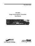
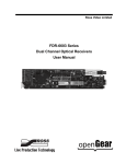
FDR-9647-LC, FDT-9648-LC, and
FDB-9649-LC
3G/HD/SD Dual Channel Fiber Receivers,
Transceivers, Transmitters User Manual
FDR-9647-LC, FDT-9648-LC, and FDB-9649-LC User
Manual
•
Ross Part Number: 9647DR-004-03
•
Release Date: June 20, 2013.
The information contained in this manual is subject to change without notice or
obligation.
Copyright
© 2013 Ross Video Limited. All rights reserved.
This work is proprietary and confidential to Ross Video Limited, its subsidiaries
and its other affiliated corporations and may not be copied, distributed, sold or
otherwise used or relied upon without the express written permission of Ross
Video Limited. Reproduction or reverse engineering of copyrighted software is
prohibited.
Patents
This product is protected by the following US Patents: 4,205,346; 5,115,314;
5,280,346; 5,561,404; 7,034,886; 7,508,455; 7,602,446; 7,834,886; 7,914,332.
This product is protected by the following Canadian Patents: 2039277;
1237518; 1127289. Other patents pending.
Notice
The material in this manual is furnished for informational use only. It is subject
to change without notice and should not be construed as commitment by Ross
Video Limited. Ross Video Limited assumes no responsibility or liability for
errors or inaccuracies that may appear in this manual.
Trademarks
•
•
1
is a registered trademark of Ross Video Limited.
is a trademark of Ross Video Limited.
•
Ross, ROSS, ROSS®, and MLE are registered trademarks of Ross
Video Limited.
•
VELCRO® is a registered trademark of Velcro Industries B.V.
•
All other product names and any registered and unregistered
trademarks mentioned in this manual are used for identification
purposes only and remain the exclusive property of their respective
owners.
Important Regulatory and Safety Notices to Service
Personnel
Before using this product and any associated equipment, refer to the
“Important Safety Instructions” listed below to avoid personnel injury and to
prevent product damage.
Product may require specific equipment, and/or installation procedures to be
carried out to satisfy certain regulatory compliance requirements. Notices have
been included in this publication to call attention to these specific requirements.
Symbol Meanings
Protective Earth — This symbol identifies a Protective Earth (PE)
terminal, which is provided for connection of the supply system’s
protective earth (green or green/yellow) conductor.
This symbol on the equipment refers you to important operating and
maintenance (servicing) instructions within the Product Manual
Documentation. Failure to heed this information may present a major
risk of damage or injury to persons or equipment.
Warning — The symbol with the word “Warning” within the
equipment manual indicates a potentially hazardous situation which, if
not avoided, could result in death or serious injury.
Caution — The symbol with the word “Caution” within the
equipment manual indicates a potentially hazardous situation which, if
not avoided, may result in minor or moderate injury. It may also be
used to alert against unsafe practices.
Warning Hazardous Voltages — This symbol is intended to alert
the user to the presence of uninsulated “dangerous voltage” within the
product enclosure that may be of sufficient magnitude to constitute a
risk of shock to persons.
ESD Susceptibility — This symbol is used to alert the user that an
electrical or electronic device or assembly is susceptible to damage
from an ESD event.
2
Important Safety Instructions
1.
Warning – Read these instructions.
2.
Follow all instructions.
3.
Refer all servicing to qualified personnel.
4.
The safe operation of this product requires that a protective earth
connection be provided. A grounding conductor in the equipment's
supply cord provides this protective earth. To reduce the risk of
electrical shock to the operator and service personnel, this ground
conductor must be connected to an earthed ground.
5.
The AC appliance inlet on the product’s power supply is the means to
disconnect the supply from the AC Mains. It must remain readily
operable for this purpose.
6.
Warning – Indoor Use: WARNING: To reduce the risk of fire or
electric shock, do not expose this apparatus to rain or moisture.
Important Laser Safety Measures and Notices
Before using this product and any associated equipment, refer to the sections
below so as to avoid personnel injury and to prevent product damage. For
further safety information when using fiver products, consult the following
publications:
•
IEC-60825-2, Safety of Laser Products - Part 2: Safety of Optical
Fiber Communication Systems (OFCS) (for use outside of the U.S.A.)
•
ANSI Z136.2, Safe Use of Optical Fiber Communication Systems
Utilizing Laser Diode and LED Sources (for use in the U.S.A.)
Products may require specific equipment, and/or installation procedures be
carried out to satisfy certain regulatory compliance requirements.
Caution — Before operating or servicing this product, all personnel
should be familiar with laser safety and fiber handling practices.
Safety Measures for Operation
During normal operation of this product, heed the following safety measures:
3
•
Do not stare at, or into, broken or damaged, fibers.
•
Do not stare at, or into, optical connectors.
•
Only properly trained and authorized personnel shall be permitted to
perform laser/fiber optic operations.
•
Ensure that appropriate labels are displayed in plain view and in close
proximity to the optical port on the protective housing/access panel of
the terminal equipment.
Safety Measures for Maintenance and Servicing
Warning — Do not use optical equipment, such as a microscope or
an eye loupe, to stare at the energized fiber end. Doing so may
damage your eyes.
During maintenance and servicing of this product, only properly trained and
authorized personnel shall be allowed to use optical test or diagnostic
equipment.
Laser Information
CLASS 1 LASER PRODUCT
IEC 60825-1:2007
Caution — INVISIBLE LASER RADIATION WHEN OPEN. AVOID
EXPOSURE TO THE BEAM.
EMC Notices
United States of America
FCC Part 15
This equipment has been tested and found to comply with the limits for a class A
Digital device, pursuant to part 15 of the FCC Rules. These limits are designed
to provide reasonable protection against harmful interference when the
equipment is operated in a commercial environment. This equipment generates,
uses, and can radiate radio frequency energy and, if not installed and used in
accordance with the instruction manual, may cause harmful interference to radio
communications. Operation of this equipment in a residential area is likely to
cause harmful interference in which case the user will be required to correct the
interference at his own expense.
Notice — Changes or modifications to this equipment not expressly
approved by Ross Video Limited could void the user’s authority to
operate this equipment.
CANADA
This Class “A” digital apparatus complies with Canadian ICES-003.
Cet appariel numerique de la classe “A” est conforme a la norme NMB-003 du
Canada.
4
EUROPE
This equipment is in compliance with the essential requirements and other
relevant provisions of CE Directive 93/68/EEC.
INTERNATIONAL
This equipment has been tested to CISPR 22:2009 and found to comply with
the limits for a Class A Digital device.
AUSTRALIA
This equipment has been tested to AS/NZS CISPR 22:2009, and found to
comply with the limits for a Class A Digital device.
Maintenance/User Serviceable Parts
Routine maintenance to this GearLite product is not required. This product
contains no user serviceable parts. If the module does not appear to be working
properly, please contact Technical Support using the numbers listed under the
“Contact Us” section on the last page of this manual. All GearLite products are
covered by a generous 3-year warranty and will be repaired without charge for
materials or labor within this period. See the “Warranty and Repair Policy”
section in this manual for details.
Environmental Information
The equipment that you purchased required the extraction and use
of natural resources for its production. It may contain hazardous
substances that could impact health and the environment.
To avoid the potential release of those substances into the environment and to
diminish the need for the extraction of natural resources, Ross Video encourages
you to use the appropriate take-back systems. These systems will reuse or
recycle most of the materials from your end-of-life equipment in an
environmentally friendly and health conscious manner.
The crossed-out wheeled bin symbol invites you to use these systems.
5
If you need more information on the collection, reuse, and recycling systems,
please contact your local or regional waste administration.
You can also contact Ross Video for more information on the environmental
performances of our products.
6
Introduction
The GearLite Dual Channel Fiber Receivers/Transmitters are high-quality signal
conversion solutions within the family of GearLite compact, self-contained
modular products.
A universal power adaptor and line cord, suitable for the country of use, is
supplied with each module. Various mounting options are included that enable a
wide range of installation choices.
FDR-9647-LC Overview
The FDR-9647-LC is a fiber optic receiver to SDI converter capable of
equalizing all common serial digital signals. Each channel of the module
equalizes the incoming SDI signal. Each channel of the module provides one
output each.
The FDR-9647-LC provides the ability to transport digital video baseband
signals over a fiber optic link, allowing for longer transport distances. SDI
outputs are re-clocked providing excellent jitter and return loss specifications.
SD/HD/3G SDI
FIBER IN 1
SD/HD/3G SDI
FIBER IN 2
OPTICAL
TO
ELECTRICAL
CONVERTER
OPTICAL
TO
ELECTRICAL
CONVERTER
HD/3G/SD SDI
OUT (BNC 1)
RECLOCKER
BUFFER
DRIVER
HD/3G/SD SDI
OUT (BNC 2)
RECLOCKER
BUFFER
DRIVER
Figure 1 Simplified Block Diagram of FDR-9647-LC Functions
7 • Introduction (Iss. 03)
FDT-9648-LC Overview
The FDT-9648-LC is a SDI to fiber optic converter capable of equalizing and
re-clocking all common serial digital signals. Each channel of the module
equalizes the incoming SDI signal, re-clocks the signal with automatic rate
detection for all popular data rates. Each channel is fully independent and can
run at different data rates.
The FDT-9648-LC provides the ability to transport digital video baseband
signals over a fiber optic link, allowing for longer transport distances. SDI
outputs are re-clocked providing excellent jitter and return loss specifications.
HD/3G/SD SDI
IN 1 (BNC 1)
EQUALIZER
RECLOCKER
BUFFER
ELECTRICAL
TO
OPTICAL
CONVERTER
BUFFER
ELECTRICAL
TO
OPTICAL
CONVERTER
HD/3G/SD SDI
IN 2 (BNC 2)
EQUALIZER
RECLOCKER
SD/HD/3G SDI
FIBER OUT 1
SD/HD/3G SDI
FIBER OUT 2
Figure 2 Simplified Block Diagram of FDT-9648-LC Functions
FDB-9649-LC Overview
The FDB-9649-LC provides one fiber optic receiver to SDI converter capable of
equalizing all common serial digital signals and one SDI to fiber optic converter
capable of equalizing and re-clocking all common serial digital signals.
HD/3G/SD SDI
IN (BNC 1)
EQUALIZER
SD/HD/3G SDI
FIBER IN
OPTICAL
TO
ELECTRICAL
CONVERTER
RECLOCKER
BUFFER
ELECTRICAL
TO
OPTICAL
CONVERTER
SD/HD/3G SDI
FIBER OUT
HD/3G/SD SDI
OUT (BNC 2)
RECLOCKER
BUFFER
DRIVER
Figure 3 Simplified Block Diagram of FDB-9649-LC Functions
Introduction (Iss. 03) • 8
Features
Each module includes the following standard features:
•
•
•
•
•
•
•
Supports major SDI formats up to 1080p 60Hz
Supports single-mode fiber
Re-clocking on all outputs at 270Mbps, 1.483Gbps, 1.485Gbps,
2.967Gbps, and 2.970Gbps
Input status indicator LEDs
Small brick form factor
5V universal adapter with locking DC connector
3-year warranty
FDR-9647-LC
In addition to the standard features, the FDR-9647-LC also includes:
•
•
Two BNC jacks for SDI outputs
Two LC/UPC PIN connectors for fiber optic inputs
FDT-9648-LC
In addition to the standard features, the FDT-9648-LC also includes:
•
•
Two BNC jacks for SDI inputs
Two LC/UPC PIN connectors for fiber optic outputs
FDB-9649-LC
In addition to the standard features, the FDB-9649-LC also includes:
•
•
•
•
One BNC jack for an SDI input
One BNC jack for an SDI output
One LC/UPC PIN connector for fiber optic input
One LC/UPC PIN connector for fiber optic output
9 • Introduction (Iss. 03)
Installation
Static Discharge
Whenever handling the modules and other related equipment, please observe all
static discharge precautions as described in the following note:
ESD Susceptibility — Static discharge can cause serious damage
to sensitive semiconductor devices. Avoid handling circuit boards in
high static environments, such as carpeted areas, and when wearing
synthetic fiber clothing. Always exercise proper grounding precautions
when working on circuit boards and related equipment.
Unpacking
Unpack each module you received from the shipping container and ensure that
all items are included. If any items are missing or damaged, contact your sales
representative or Ross Video directly.
Working with Fiber Optic Connectors
Keep the following in mind when working with fiber optic connectors:
•
•
•
Every time you are required to insert a connector into a device or
mating sleeve, you must clean the connector. All exposed surfaces of
the ceramic ferrule must be clean. Follow your facility practices of
cleaning fiber optic connectors.
Connectors must always be inserted into a device or have a dust cap on.
A poor optical connection is often similar to a poor electrical
connection. Try removing the connector, cleaning, and re-inserting the
connector. A bad connection can result in experiencing instability of
signal, high loss, or a noisy signal.
Mounting and Installation
The module can be mounted in any convenient location. However, to ensure
long life for this product, observe the following precautions and operating
requirements:
•
•
Maintain an ambient temperature of 0°C to 40°C (32°F to 104°F).
Allow for air circulation around the chassis for convectional cooling.
Installation (Iss. 03) • 10
Many different mounting positions are possible. Some installation options are
permanent and require careful consideration of the final positioning before
installation. Please note that in some mounting locations, the power adaptor
must be affixed in a similar manner as the chassis.
Other possible options include the use of adhesive magnetic sheets (not
included) affixed to the chassis and the power adaptor, for removable mounting
on metal cabinets etc.
Cable ties may be necessary in some applications to relieve strain on the
mounting hardware and the connectors.
Surface Mount Strips
The included VELCRO® brand surface mount strips allow the GearLite module
and power supply to be affixed to a permanent location during use and easily
removed for adjustments. Carefully consider the installation location before
proceeding; the adhesive is very aggressive and is not easily removed. The
adhesive will cure fully in 24 hours.
To install the Surface Mount Strips
1.
Remove the Protective Backing Film from the adhesive on the
bottom of the two VELCRO® brand Surface Mount Strips.
2.
Adhere the Surface Mount Strips to the bottom side of the chassis.
(Figure 4)
SURFACE MOUNT
STRIPS
SERIAL NUMBER
LABEL
PROTECTIVE
BACKING FILM
Figure 4 Surface Mount Installation Option
3.
Remove the Protective Backing Film from the other side of the
VELCRO® brand Surface Mount Strips.
4.
Press the chassis into position on the surface you want to mount it to.
Operating Tip — An additional VELCRO® brand Surface Mount
Strip is available to mount the power adapter.
Non-Slip Pads
Four non-slip adhesive pads have been supplied for desktop placements. Simply
remove the protective backing film from the adhesive and affix one non-slip pad
to each of the four corners on the bottom of the chassis.
11 • Installation (Iss. 03)
Setup and Operation
Power Adapter and Supply
Connect the PS-9000 power adaptor to the power supply connector. The
PS-9000 provides regulated +5V DC (5%) @ up to 2A. The DC power cord has
a locking connector that securely fastens into the power supply DC jack on the
GearLite chassis. The chassis has a standard miniature power jack (center pin
positive). Refer to the section “Important Regulatory and Safety Notices to
Service Personnel” on page 2 for details.
If using an adaptor other than the PS-9000, ensure that:
•
•
•
the polarity is correct
the voltage is +5V DC regulated to 5%
sufficient current for the GearLite module is supplied
Caution — Use of improper adaptors may damage your GearLite
module and will void the warranty.
Cable Connections Overview
Caution — Never attempt to look down the barrel of a connected
fiber or device transmitting an optical signal. The transmitted light is
not in the visible spectrum and may cause permanent eye damage.
Turn off all laser sources before disconnecting devices.
BNC Connections
There are five connections on each module:
•
•
•
Two BNC jacks for the SDI signals
Two single-mode, LC/UPC PIN connectors for the fiber optic signals
A power supply connection to the GearLite PS-9000 power adaptor
BNC 1
OPTIC
PORT 1
BNC 2
Figure 5 BNC Connections
OPTIC
PORT 2
POWER
SUPPLY
Figure 6 Fiber and Power Connections
Setup and Operation (Iss. 03) • 12
Connect the BNC cables to the module according to the designations indicated
on the chassis label, Figure 5, and Table 1. If the input source is successfully
detected, the corresponding LOCK SDI LED will light solid green. It is not
necessary to terminate unused outputs.
Table 1 BNC Cabling Designations
Product
BNC
Connection
1
SDI OUT 1
2
SDI OUT 2
1
SDI IN 1
2
SDI IN 2
1
SDI IN
2
SDI OUT
FDR-9647-LC
FDT-9648-LC
FDB-9649-LC
Fiber Connections
Before connecting your fiber optic signals:
•
•
•
Refer to the section “Important Laser Safety Measures and Notices”
on page 3 for safety information before handling fiber optic devices.
Remove the dust cap from the fiber port connectors on the module
before connecting your fiber optic signals.
Ensure that the exposed surface of the ceramic ferrule of each
connector is clean. Refer to the section “Working with Fiber Optic
Connectors” on page 10 for cleaning tips.
Connect the fiber optic cables to the module according to the designations
indicated on the chassis label, Figure 6, and Table 2. If the input source is
successfully detected, the corresponding LOCK OPTO LED will light solid
green.
Table 2 Fiber Cabling Designations
Product
Fiber Port
Connection
1
FIBER OPTIC IN 1
2
FIBER OPTIC IN 2
1
FIBER OPTIC OUT 1
2
FIBER OPTIC OUT 2
1
FIBER OPTIC IN
2
FIBER OPTIC OUT
FDR-9647-LC
FDT-9648-LC
FDB-9649-LC
13 • Setup and Operation (Iss. 03)
Status LEDs
Each module includes two LEDs that display the status of the input signal
activity. These LEDs are located above the fiber optic connectors (Figure 7).
Table 3 describes the functions the LEDs for each module type.
LED 1
LED 2
Figure 7 Right-edge Status Indicator LEDs
Product
LED
1
Table 3 LED Descriptions
Reports
LED Color
Status of
Function
Green
LED is lit green when there
is a valid video signal on
the IN 1 fiber connector
Red
LED is lit red when there is
an invalid fiber optic signal
Green
LED is lit green when there
is a valid video signal on
the IN 2 fiber connector
Red
LED is lit red when there is
an invalid fiber optic signal
Green
LED is lit green when there
is a valid SDI signal on the
IN 1 BNC
Red
LED is lit red when there is
an invalid SDI signal
Green
LED is lit green when there
is a valid SDI signal on the
IN 2 BNC
Red
LED is lit red when there is
an invalid SDI signal
FIBER
OPTIC IN 1
FDR-9647-LC
2
1
FIBER
OPTIC IN 2
SDI IN 1
FDT-9648-LC
2
SDI IN 2
Setup and Operation (Iss. 03) • 14
Product
LED
1
Table 3 LED Descriptions
Reports
LED Color
Status of
Function
Green
LED is lit green when there
is a valid video signal on
the IN fiber connector
Red
LED is lit red when there is
an invalid fiber optic signal
Green
LED is lit green when there
is a valid SDI signal on the
SDI IN BNC
Red
LED is lit red when there is
an invalid SDI signal
FIBER
OPTIC IN
FDB-9649-LC
2
SDI IN
15 • Setup and Operation (Iss. 03)
Specifications
Table 4 provides the technical specifications for all modules unless otherwise
noted. Specifications are subject to change without notification.
Table 4 Technical Specifications
Category
Parameter
Specification
SDI Inputs/
Outputs
Fiber Inputs/
Outputs
Standards
Accommodated
SMPTE 259M, SMPTE 292M, SMPTE 424M
Input Voltage
800mV, nominal
SDI Data Rate
270Mbps, 1.5Mbps, and 3Gbps
Impedance
75ohm
Input Cable
Equalization
SD: 100m
HD: 100m
3G: 80m
Return Loss
-12dB (all formats)
Standards
Accommodated
SMPTE 259M, SMPTE 292M, SMPTE 424M
Operating Wavelength
Range
1310nm
Input Power Operating
Range (Color Bars)
-3dBm to -18dBm @ 2.97Gbps
-3dBm to -19dBm @ 270Mbps and 1.5Gbps
Input Power Operating
Range (Pathological)
-3dBm to -17dBm @ 2.97Gbps
-3dBm to -18dBm @ 270Mbps and 1.5Gbps
Receiver Overload
At values above -3dBm
Output Center
Wavelength
+/- 20nm
Output Power
-7dBm to -2dBm
Output Laser Type
Fabry-Perot (FP)
Connector Types
Single Mode, LC/UPC PIN
Required Voltage
+5v DC
Maximum Power
5W
Thermal Environment
0°C to 40°C (32°F to 104°F) ambient,
non-condensing
Power
Environment
Specifications (Iss. 03) • 16
Category
Table 4 Technical Specifications
Parameter
Specification
Dimensions
13cm x 4cm x 2cm
(5.25” x 1.75” x 0.75”)
Weight
170g (6oz)
Other
17 • Specifications (Iss. 03)
Service Information
Warranty and Repair Policy
The GearLite Product is warranted to be free of any defect with respect to
performance, quality, reliability, and workmanship for a period of THREE (3)
years from the date of delivery to the customer. In the event that your GearLite
module proves to be defective in any way during this warranty period, Ross
Video Limited reserves the right to repair or replace this piece of equipment
with a unit of equal or superior performance characteristics.
Should you find that this GearLite Product has failed after your warranty period
has expired, we will repair your defective product should suitable replacement
components be available. You, the owner, will bear any labor and/or part costs
incurred in the repair or refurbishment of said equipment beyond the THREE (3)
year warranty period.
In no event shall Ross Video Limited be liable for direct, indirect, special,
incidental, or consequential damages (including loss of profits) incurred by the
use of this product. Implied warranties are expressly limited to the duration of
this warranty.
This GearLite User Manual of our Digital Products line provides all pertinent
information for the safe installation and operation of your GearLite Product.
Ross Video policy dictates that all repairs to the GearLite module are to be
conducted only by an authorized Ross Video Limited factory representative.
Therefore, any unauthorized attempt to repair this product, by anyone other than
an authorized Ross Video Limited factory representative, will automatically
void the warranty. Please contact Ross Video Technical Support for more
information.
In Case of Problems
Should any problem arise with your GearLite Product, please contact the Ross
Video Technical Support Department. (Contact information is supplied at the
end of this publication.)
A Return Material Authorization number (RMA) will be issued to you, as well
as specific shipping instructions, should you wish our factory to repair your
GearLite Product. If required, a temporary replacement module will be made
available at a nominal charge. Any shipping costs incurred will be the
responsibility of you, the customer. All products shipped to you from Ross
Video Limited will be shipped collect.
The Ross Video Technical Support Department will continue to provide advice
on any product manufactured by Ross Video Limited, beyond the warranty
period without charge, for the life of the equipment.
Service Information (Iss. 03) • 18
Contact Us
Contact our friendly and professional support representatives for
the following:
•
Name and address of your local dealer
•
Product information and pricing
•
Technical support
•
Upcoming trade show information
Technical
Support
Telephone: +1 613 • 652 • 4886
After Hours Emergency: +1 613 • 349 • 0006
Email: [email protected]
Telephone: +1 613 • 652 • 4886
General
Information
Fax: +1 613 • 652 • 4425
Email: [email protected]
Website: http://www.rossvideo.com
Visit Us
Visit our website for:
•
Company information and news
•
Related products and full product lines
•
Online catalog
•
Testimonials