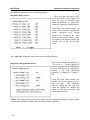
1
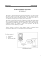
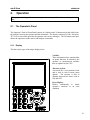
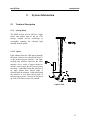
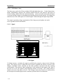
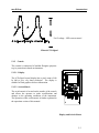
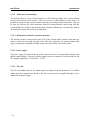
OPERATING AND SERVICE MANUAL
MPR E-S CAN
Microprocessor Refractometer with Color Display
Designed and Manufactured by
THE ELECTRON MACHINE CORPORATION
15824 CR 450 West
Post Office Box 2349
Umatilla, FL 32784-2349
110525
(352)-669-3101
FAX: (352)-669-1373
E-Mail: [email protected]
http://www.electronmachine.com
MPR E-SCAN
INTRODUCTION
Introduction
The Electron Machine Corporation
MPR E-SCAN
The E-Scan is a microprocessor driven critical angle refractometer. It is used to measure
the refractive index of process fluids which directly correlate with customer request for
dissolved solids, Brix or other meaningful measurement. The E-Scan may be used as an
error indicator or an integral part of a complete process control system.
The E-Scan is equipped with a broad range of diagnostics to aid in fault isolation without
the use of special test equipment. The instrument is calibrated before leaving the factory
and should not need recalibration unless some modification is made to the sensing head.
Calibration procedures are available to change system parameters and allow the
refractometer to measure different process fluids.
Extensive literature is available for various industries listing the correlation between
refractive index, degrees Brix, or % solids and specific process parameters.
The E-Scan consists of:
•
•
•
Sensing head
Console
Interconnecting cable
MPR E-Scan Overview
1
MPR E-SCAN
INTRODUCTION
Important Manual Information
The Chapter title is at the top of each page for quick reference through the manual.
Important points, reminders, and warning messages are printed in bordered boxes as:
NOTE: Box indicates important messages.
This is a general use manual. In the back of the manual are addendums and
configuration information specific to the individual unit.
CAUTION
When removing the sensing head from an operating line, do not assume that
the line is empty or that the isolation or bypass means is working properly.
If an EMC isolation valve is used, be sure its travel is not limited by any
external attachments or other interference and the valve is closed tightly. No
pressure should be felt on the head as the mounting nut is being removed.
ANY PRESSURE FELT WHEN THE NUT IS LOOSENED MUST BE
INVESTIGATED BEFORE PROCEEDING. Steam should be turned off
before attempting to remove the head.
Use a face shield and protective clothing. Stand to the side when removing
the sensing head.
Clean all black liquor residue from spud-piece on adapter prior to re- insertion
of sensing head. The o-ring seal should be replaced before re- installation.
2
Table of Contents
1.
Installation............................................................................................................... 1 - 1
1.1 Site Selection..............................................................................................1 - 1
1.2 Power Requirements...................................................................................1 - 1
1.3 Attaching the Sensing Head .......................................................................1 - 1
1.4 Steam Purge Attachment ............................................................................1 - 2
1.5 Interconnection...........................................................................................1 - 3
1.5.1 Analog Outputs............................................................................... 1 - 3
1.5.2 Printer Output .................................................................................1 - 4
1.6 Prism Clean ................................................................................................1 - 4
1.6.1 Steam Pressure................................................................................1 - 4
1.7 Start-Up ......................................................................................................1 - 4
2.
Operation................................................................................................................. 2 - 1
2.1 The Operator's Panel...................................................................................2 - 1
2.1.1 Display............................................................................................ 2 - 1
2.1.2 Button Touch Pad Function Chart ..................................................2 - 2
2.1.3 Measurement Signal Graphing for the MPR E-Scan .....................2 - 3
2.2 Normal Mode..............................................................................................2 - 4
2.2.1 What Normal Mode Does................................................................2 - 4
2.2.2 System Indicators ...........................................................................2 - 4
2.2.3 The Menu Options in Normal Mode ..............................................2 - 5
2.2.4 Overview of Menu Options ............................................................2 - 6
2.3 Product Selection........................................................................................2 - 7
2.4 Calibration Selection................................................................................2 - 10
2.5 Configuration Selection............................................................................2 - 15
2.6 Print Selection ..........................................................................................2 - 20
2.7 Diagnostic Selection.................................................................................2 - 21
2.8 Offset Selection........................................................................................2 - 24
2.9 Purge Selection.........................................................................................2 - 25
2.10 Hold Selection..........................................................................................2 - 26
3.
Problem Analysis .................................................................................................... 3 - 1
3.1 Procedures ..................................................................................................3 - 1
3.2 Trouble Shooting Chart ..............................................................................3 - 2
4. Service..................................................................................................................... 4 - 1
4.1 EMC Warranty ...........................................................................................4 - 1
4.2 Return of Defective Parts ...........................................................................4 - 1
4.3 Service in the Field .....................................................................................4 - 1
4.4 Spare Parts ..................................................................................................4 - 2
4.4.1 How to Order Parts .........................................................................4 - 2
4.4.2 Available Spare Parts .......................................................................4 - 2
4.5 Preventive Maintenance .............................................................................4 - 3
4.6 Caution .......................................................................................................4 - 3
4.7 Maintenance Log Sheet ..............................................................................4 - 4
5.
System Information................................................................................................. 5 - 1
5.1 Technical Description................................................................................5 - 1
5.1.1 Sensing Head ................................................................................5 - 1
5.1.1.1 Optics ........................................................................... 5 - 1
5.1.1.2 CCD Linear Array.......................................................... 5 - 2
5.1.1.3 Signal ............................................................................. 5 - 2
5.1.2 Console ..........................................................................................5 - 3
5.1.2.1 Display........................................................................... 5 - 3
5.1.2.2 Switch Matrix................................................................. 5 - 3
5.1.2.3 Cable entry and mounting .............................................. 5 - 4
5.1.2.4 IB (interface board) for external connection................. 5 - 4
5.1.2.5 Power supply.................................................................. 5 - 4
5.1.2.6 I/O card .......................................................................... 5 - 4
5.1.2.7 CPU Card ....................................................................... 5 - 5
5.1.2.8 Supplemental Card Information..................................... 5 - 6
5.2 Refr actometer Specifications ......................................................................5 - 7
5.3 Available Options .......................................................................................5 - 7
6.
Drawings List .......................................................................................................... 6 - 1
MPR E-SCAN
1.
Installation
1.1
Site Selection
INSTALLATION
The E-Scan console can be mounted in any area where ambient conditions allow personnel to
remain for extended periods. The cabinet is Nema 4X rated and should be kept closed.
MPR E-Scan Instrument
1.2
Power Requirements
The A.C. power should be supplied from a line which is not
subjected to power interruptions or heavy inductive loads. A.C.
power can be 120/220 VAC at 50 or 60 Hertz.
1.3
Attaching the Sensing Head
Care must be taken not to damage the thermistor probe
protruding from the sensing head on units so equipped.
The sensing head as received will have a protective sleeve
around the probe area.
To facilitate fast thermal response the tip and walls of the probe
are very thin making it somewhat fragile.
The sensing head is attached to the process line by an adapter
which can be carbon steel, stainless steel (316) or a material
specified by the customer. This adapter must not be placed in an
area where vibration is severe or excessive.
Sensing Head to Adapter
Positioning.
The adapter should be oriented to place the head in a horizontal
plane to assure that deposit buildup and air pocket creation will be
minimal.
If the sensing head is to be mounted on a vertical pipe, the fluid
flow should be upward. The arrow on the adapter should point in
the direction of fluid flow. (See Head to Adapter Positioning.)
1-1
MPR E-SCAN
INSTALLATION
The probe end of the sensing head has a groove for an interface o-ring.
This o-ring must be in place prior to installing the head into the adapter to prevent the process
leaking out.
The head is attached to the adapter by a 2- inch sanitary nut.
The nut should be tightened with a wrench (supplied by EMC) to a maximum 50 foot pounds
of torque (68 Newton-Meter).
Alignment marks are provided for units utilizing a steam purge cleaning cycle to ensure that
the thermistor probe will not be in a direct line of the steam blast. (See drawing below.)
The sensing head houses optical components which are susceptible to the effects of moisture.
The cover is moisture proof and contains a small amount of desiccant to absorb any moisture
remaining in the head after assembly. The sight glass on the head allows inspection of the
desiccant. Light orange indicates that it remains effective. Clear indicates it is no longer
effective and must be changed. The desiccant can be renewed by heating to approximately
250° F (121° C) until it recovers its orange color.
1.4 Steam Purge Attachment
Steam Purge Attachment - for liquids
which exhibit a tendency to "coat"
The steam purge valve must be similarly
mounted to the adapter with a minimum of 6"
and a maximum of 18" from the steam port on
an adapter preferably with 1/4" tubing.
It is essential that NO LEAKS be present in this
line that could allow evaporation of liquids,
thereby plugging the purge line .
Steam pressure must be at least 50 psi (3.44 bar)
above process pressure but less than 100 psi
(6.89 bar) above process pressure with adequate
condensate drainage at the steam valve in order
to ensure hot steam for cleaning the prism. Trial
and error must, of necessity, be employed in
determining the minimum steam time necessary
for proper steam cleaning of the prism due to
variables from application to application.
Steam purge time must be kept at a minimum typically from 1 to 10 seconds duration, to avoid
excessive prism deterioration, while at the same time keeping the intervals between these purge
times at maximum, which may vary from minutes to many hours.
1-2
MPR E-SCAN
1.5
INSTALLATION
Interconnection
The E-Scan offers many options for external device connections.
1.5.1 Analog Outputs
In addition to voltage outputs, the EScan also offers current outputs for the
measurement and also the temperature.
The measurement is a standard output
and temperature is an option. Output
for these readings is a 4 to 20 mA
signal that is referenced to ground
(non- isolated) so that any device that is
connected to these outputs must have a
floating (or isolated) input. Isolated
current output modules are available as
an option.
The output for the measurement
reading is found on TB 3 terminals 1
and 2. Terminal 1 is the positive output
for both the isolated output option and
the standard non isolated output
module. The output for the temperature
is located on TB 3 terminals 3 and 4, 3
being the positive output in this case.
The modules on the top of the interface
board represent the output modules.
The one on the left U1 is the output
module for the measurement. U2 is the output module for the temperature. The other modules
(U3 and U4) are for optional features and are explained in the optional addendums to this
manual. It is an easy process to change from a non- isolated module to an isolated output module.
You must first remove the power supply, then unplug the non- isolated module and replace it with
the isolated module. The isolated modules are blue potted modules while the non- isolated
modules are bare board modules. If a 0-10 voltage output is desired then TB 4 terminal 1 is the
measurement output and terminal 2 is the temperature output. Terminal 3 is the common for
both of these outputs.
The cable should not be placed in a tray or conduit with wires attached to heavy inductive loads
or SCR drives. A separate conduit is recommended.
1-3
MPR E-SCAN
INSTALLATION
1.5.2 Printer Output
The E-Scan offers a printer output as an option via CPU card parallel port J17. The connector is
easily installed either in the field or at the time the instrument is manufactured. The standard
printer output is via the Com/LPT card. Please refer to interconnection drawing for the Com/LPT
Card for the proper connection of a printer to the E-Scan. The printer output should be used for
short runs only, less than 50 feet (15.2 meters). If a longer cable is desired then a printer buffer
should be used to extend the cable length.
1.6
Prism Clean
The following refers to steam, however, other mediums may be used as the prism cleaning agent:
The E-Scan provides two normally open contacts for prism clean. These contacts are intended to
directly operate the steam (TB2-11,12) and condensate drain (TB2-9,10) valves. Electrical
interconnection for these devices is also shown in the interconnection drawing. These contacts
are dry contacts and power must be supplied from an external source as shown on the drawing.
1.6.1 Steam Pressure
The steam pressure must be no less than 50 psi (3.44 bar) and no greater than 100 psi (6.89 bar)
above the process line pressure. Both the steam and condensate drain valves should be located
as close to the steam purge fitting as possible. The condensate drain valve is provided to remove
water from the steam line to allow free passage of steam to the head. See also Steam Purge
Attachment in Installation Section.
1.7
Start-Up
Turn power on. Allow sufficient time for the sensing head to stabilize at the process
temperature. It is recommended that no adjustments be made for at least 15 minutes after startup.
Compare the reading against a sample taken from the process line close to where the unit is
installed and at the process operating temperature. If the sample does not equal the displayed
reading, adjust the analog zero per Operation/Calibration section.
Important: Prior to shipment the sensing head is matched to the console and factory calibrated.
DO NOT ATTEMPT TO RE-CALIBRATE
1-4
MPR E-SCAN
2.
OPERATION
Operation
This equipment is designed for continuous operation and may be left on for extended periods of
time.
2.1
The Operator's Panel
The Operator’s Panel or Front Panel consists of a display and a 20-button touc h pad which form
the interface between the operator and the instrument. The display consists of a 640 x 480 pixel
TFT LCD screen which provides the operator with various messages. The 20 button touch pad
allows the operator to make entries and instigate commands.
2.1.1 Display
The three basic types of messages displayed are:
Variable :
These information lines contain either
set points that may be altered by the
operator, or measurement variables
that are updated by the CPU.
Alternate Action:
Acts much like a two position switch
and is used to select various menu
options. The operator is able to
alternate between two states, such as
ON and OFF.
Error Display:
Flashes continuously to attract
operator’s attention to an error
condition.
2-1
MPR E-SCAN
OPERATION
2.1.2 Button Touch Pad Function Chart
Scrolls cursor horizontally to the left
and also used to initiate editing of calibration voltages in
the calibration table, and temperature values in the
compensation table.
Scrolls cursor horizontally to the
right and also used to initiate editing of all system
parameters excluding those accessed by the LEFT
ARROW.
Scrolls cursor vertically in the “Up” direction.
Scrolls
cursor
vertically
in
the
“Down” direction.
ENTER
Used to select all cursor items and to save edited data.
Esc
Used to abort to previous
operation without saving edited data.
Menu
Used to immediately display the normal
mode of operation without saving information or main
menu selections if already in normal mode.
PgUp
Displays previous screen of information or
mode of operation when indicated on the screen. Used to
exit graph mode and return to normal mode.
PgDn
Displays the next screen of information or
mode of operation when indicated on the screen. Used to
enter graph mode from normal mode.
+/-
Allows data fields to be either
positive or negative. Toggles configuration and diagnostic
options as well as control modes, if configured for P.I.D.
control. Also used to record sample readings used for
analog zero adjustment.
0-9
Numeric keys used to input data.
2-2
MPR E-SCAN
OPERATION
2.1.3 Measurement Signal Graphing for the MPR E-Scan
Graph Mode Screen
The MPR E-Scan offers a
graphical mode display which
can be accessed from the normal
mode of operation via the PgDn
button on the front panel switch
matrix. PgUp will then return to
the normal mode display. The
graphical mode display comes
equipped with all the essential
information
including
the
current product, error status, and
measurement
reading,
in
addition to the graph span and
time.
The graph span limits are derived
from the analog low and high
limits in calibration and are drawn on the display at the top and bottom of the graph area as
dotted lines.
The graph time can range from 5 minutes to 9999 minutes and can be accessed via
the button on the front panel switch matrix.
The calibration alarm limits are also displayed graphically within the graph area and are drawn
as red dashed lines to differentiate them from the graph span limits. The alarm limit lines are
drawn 20 pixels apart horizontally, which gives the added feature of breaking the graph time into
20 equal parts. Thus, if the graph time were 20 hours, each alarm limit segment would represent
1 hour.
Finally, the measurement signal itself is drawn in the graph area and can be recognized as a
single continuous stream of information that is 2 pixels thick. The measurement graph offers a
high quality display with 574 pixels of horizontal and 295 pixels of vertical resolution.
2-3
MPR E-SCAN
2.2
OPERATION
Normal Mode
2.2.1 What Normal Mode Does
In normal mode the system displays the following information:
•
•
•
•
•
•
•
•
•
Name of the current product being measured along with an associated product number.
Software version number.
Current time and date.
On-line measurement such as BRIX, SOLIDS....
On-line temperature in Degrees Fahrenheit and Centigrade.
Alarm points for measurement and temperature.
Error status for system measurement, temperature and voltage levels.
Graphics menu to allow access to other MPR E-Scan system features.
Purge information when configured for purge operation.
Note: In normal mode set points cannot be changed or adjustment s made.
2.2.2 System Indicators
C
Isolation valve is closed. The MPR E-Scan will not initiate a prism clean.
T
Below min purge temperature limit. No prism clean allowed.
H
Measurement Hold. Current readings and analog outputs are maintained until complete.
Can be invoked by menu selection in normal mode or by external input if configured for
on demand hold. Measurement Hold can also indicate a cleaning cycle in progress which
is indicated by a purge message as well as a current measurement voltage display while
in normal mode.
P
Purge failed. This means the previous purge cycle did not properly clean the prism. This
indicator is used only when smart prism cleaning is configured.
O
Measurement over range. Current reading above last calibration point for MPR E-Scan
in the calibration table.
U
Measurement under range. Current reading below first calibration point for MPR E-Scan
in the calibration table.
S
Measurement sample reading has been recorded as the reference for analog zero
adjustment.
2-4
MPR E-SCAN
OPERATION
2.2.3 The Menu Options in Normal Mode
Normal mode is entered by default, upon power up. To gain access to other system features
select the MENU button on the Front Panel To uch Pad.
Note: The screen names and setpoints below are just an example, they will vary from
application to application.
Normal Mode Screen With Menu Options
When the MENU button is
selected, the following menu
options are displayed on the
normal mode screen:
Normal Mode Screen With Purge and Hold Options
If
“Purge” and
“Hold”
options are configured, the
following menu options are
displayed on the normal mode
screen:
2-5
MPR E-SCAN
2.2.4
OPERATION
Overview of Menu Options
PRODUCT option allows the operator to select a product from a list of previously calibrated
products. When a new product is chosen, all operating parameters are automatically loaded so
that the E-Scan can immediately be ready to measure the “new” product selected. This menu
option also allows the operator to enter actual product names which are attached to associated
product numbers. In addition, this option enables the operator to create new products by storing
product information into unused product numbers.
CALIB option allows the operator to enter calibration set points. This consists of calibration
limits, measurement, temperature compensation, and analog zero adjustment. Since a complete
calibration is performed in advance by EMC, it would be a rare condition for the operator to
access calibration measurement and temperature compensation. However, system limits may be
changed more frequently if the operator chooses to change the alarm limits, analog output limits,
alarm delays, purge cycle information, or other limits. An analog zero adjustment is provided to
“zero in” the instrument to match lab samples or reach a target measurement if needed.
CONFIG option allows the operator to configure the E-Scan to perform various functions. Such
configurations would include: purge/hold interface, smart cleaning, measurement and
temperature alarms, 232 output and associated baud rates, measurement title, and displayed
reading decimal format. Other configuration options are selected in advance by EMC and would
not normally be changed by the operator. Thus, access to other system configurations is gained
only by entering a correct password.
PRINT option allows the operator to print all system calibration and configuration settings as
well as current measurement and temperature readings with a time and date stamp.
DIAG option provides the operator with data that can be used to test and troubleshoot system
problems. The operator can display all voltages from the sensing head, test relays on the
interface board, output min., mid., and max. analog data to test and calibrate chart recorder
output, and enter system time and date in cases of battery failure.
ANLG. 0 Same as “ANLG. 0” in calibration menu
OFFSET option allows the operator to add an adjustment to the current reading in order to reach
a target value.
PURGE option allows the operator to initiate a purge from normal mode in addition to the
automatic purge cycle timing setup in calibration limits. The purge function cleans the sensing
head prism and if configured for smart cleaning will automatically start another purge cycle if
the previous purge was unsuccessful. Purge can be aborted using the Front Panel ESC button.
HOLD option allows the operator to initiate a hold condition from normal mode, which will
freeze system information. This freezes both displayed readings as well as analog output. Hold
can be aborted using the Front Panel ESC button.
2-6
MPR E-SCAN
2.3
OPERATION/PRODUCT SELECTION
Product Selection
P Product Screen
The product menu displays the
current product selected, a list of all
available products, and three menu
options: “Get”, “Store”, and
“Name”. Using the Front Panel
buttons the operator can highlight
and then select specific menu
options.
The “Get” option allows the
operator to choose a specific
product, provided this product has
been previously calibrated and
configured for on demand use. In
this example, only two products
(“PRODUCT 1 NAME” and
“PRODUCT 2 NAME") are
available.
When the “Get” option is selected, the following is displayed:
Get Mode Screen
The product menu options have
been replaced by the “Get Mode”
and “Enter Product #” messages.
Using the Front Panel buttons the
operator can enter a product number
and then “Get” that product.
NOTE: The operator can only
“Get” products that are available
which are identified by a product
name.
2-7
MPR E-SCAN
OPERATION/PRODUCT SELECTION
The second menu optio n, “Store”, allows the operator to create a new product by selecting a
product number that will be the destination for the current product calibration and configuration
information.
When the “Store” option is selected, the following is displayed:
Store Mode Screen
The product menu options have been
replaced by the “Store Mode” and
“Enter Product #:” messages.
Using the Front Panel buttons, the
operator can select a product number
that will be the destination of the
current calibration and configuration.
In this example, all of product 01
information will be copied to product
03 thus creating a new product.
The next step would be to assign a meaningful name to the newly created product which can be
accomplished by selecting the third product menu option, “Name”.
Name Mode Screen
The product menu options have been
replaced by the “Name Mode” and
“Enter Product#:” messages.
In this example we will assign a
meaningful name to a newly created
product. Notice product 03 is
designated by the message “NEW
PRODUCT”, indicating that it has
been newly created by the “Store”
product menu option.
2-8
MPR E-SCAN
OPERATION/PRODUCT SELECTION
Using the Front Panel buttons, product 03 can be selected which would result in the following
display:
Name Mode Alphabet Screen
This is the product name mode alphabet menu.
It displays the current product selected
in the upper left corner, the alphabetic
characters available for assigning a
product name in the center, and the
product name at the bottom which is
updated as characters are selected.
Using the Front Panel ARROWS and
the ENTER button a product name
can be selected and then saved. The
“PgDn” and “PgUp” messages at the
bottom right indicate the status of the
editing mode. Toggling between these
modes allows the operator to move
the edit cursor to a desired position
either in the alphabet or the product name. When the “-Save-” option is selected the product
name is saved.
Note: Up to 99 products are available. The operator can use the “PgDn” and “PgUp” buttons
to view a set of 20 products per page.
2-9
MPR E-SCAN
2.4
OPERATION/CALIBRATION
Calibration Selection
Calibration Mode Screen
The calibration menu contains four
menu options:
1. Limits - This option contains
the system limits for alarms, purge
cycle, analog output, filter weight,
measurement scale and offset.
2. Meas. - This option allows entry
to the calibration measurement
routine. This is used to calibrate
the process measurement so that a
linear interpolation can be made to
get the Refractive Index based on
the current measurement voltage.
3. Temp. - This option allows entry to the calibration temperature compensation routines. This
is used to compensate the process measurement changes that are caused by temperature changes.
4. Anlg. 0 (Analog Zero) - This option is used to adjust or “zero in” the instrument to match a
target value.
Calibration Limits Screen 1
Using the Front Panel buttons, the
operator can highlight and then select
the specified calibration menu
options. Selecting the “Limits” menu
option would generate the following
display:
Using the Front Panel arrow buttons,
the operator can scroll through and
edit selected system limits. In this
example, Measurement Alarm Low
can now be changed using the
RIGHT ARROW button and the
numeric keys.
Measurement Alarm Low: If the measurement falls below this limit, a system alarm is
activated. An error message will appear in the status window in normal mode, and the low
measurement alarm relay will be turned on.
2-10
MPR E-SCAN
OPERATION/CALIBRATION
Measurement Alarm High: If the measurement exceeds this limit, a system alarm is activated.
An error message will appear in the status window in normal mode, and the high measurement
alarm relay will be turned on.
Measurement Alarm Delay: This is the alarm delay time in seconds for the process
measurement that must expire while a limit is exceeded before an error is activated.
Temperature Alarm Low: If the temperature falls below this limit, a system alarm is activated.
An error message will appear in the status window in normal mode, and the low temperature
alarm relay will be turned on.
Temperature Alarm High: If the temperature exceeds this limit, a system alarm is activated.
An error message will appear in the status window in normal mode, and the high temperature
alarm relay will be turned on.
Temperature Alarm Delay: This is the alarm delay time in seconds for the process temperature
that must expire while a limit is exceeded before an error is activated.
Purge Cycle Time : This is the time interval in minutes between automatic purging. During
purging, all system readings and analog outputs are frozen. A “0" setting disables automatic
purging.
Condensate Drain Time: When the purge cycle is activated, this is the time in seconds that
elapse before a prism clean occurs. During this time the condensate drain relay is activated and
condensation is allowed to drain before steam cleaning.
Prism Clean Time : This is the time in seconds during which cleaning of the prism occurs and
the prism clean relay is activated.
Calibration Limits Screen 2
Page 2 contains the following limits:
Hold Delay Time : This is the time in
seconds that elapse after a prism clean
occurs. This time allows a delay to
occur before resuming normal process
measurement.
Meas. Anlg. Min. Output: This is the
measurement reading that will
produce a 4 mA or 10 volt output.
Meas. Anlg. Max. Output: This is
the measurement reading that will
produce a 20 mA or 10 volt output.
2-11
MPR E-SCAN
OPERATION/CALIBRATION
Temp. Anlg. Min. Output: This is the temperature reading that will produce a 4 mA (optional)
or 0 volt output.
Temp. Anlg. Max. Output: This is the temperature reading that will produce a 20 mA
(optional) or 10 volt output.
Filter Weight: This is a value that controls system response time to process measurement
changes. The larger the value the slower the response time. The filter weight divided by 10 will
give approximate response time in seconds to achieve 63% output of a step input change.
Meas urement Scale Base: This is a base value for the measurement scale. If set to zero, the
measurement will be scaled from the calibration table or else from the given base.
Measurement Scale: This is a scale for the process measurement that allows fine tuning so that
the reading can be adjusted to match lab samples. The default is 100%. The formula for scaling
is as follows: NEW MEAS = (((Current Meas. - Base) * Scale) + Base)
Measurement Offset: This is the value that is added to the current measureme nt in order to
“zero-in” a target reading.
Page 3 of calibration limits screen contains:
Min. Purge Temperature: This is the value that causes the “T” indication to come on and
limits any further purging
Selecting the “Meas.” option from the calibration menu results in the following display:
Calibration Measurement Screen
The calibration measurement table is
created when you place actual
solution samples to be measured on
the sensing head and then save the
desired measurement reading for that
sample along with the current
measurement voltage. This table is
graphically
equivalent
to
approximating a measurement curve
with a series of straight lines.
Use the RIGHT ARROW button on
the Front Panel to edit the sample
value, and ENTER to capture the
measurement voltage. To give the
operator more flexibility, the voltages
can also be edited by using the LEFT ARROW button. Select the ENTER button to
permanently save calibration.
2-12
MPR E-SCAN
OPERATION/CALIBRATION
An example of what is displayed while calibrating Sample #1 is shown below:
Calibration Sample Example Screen
At this point, sample #1 should be
on the sensing head, and a sample
value should be entered. When the
ENTER button is selected, the
measurement voltage displayed at
the bottom is put in the table as the
measurement voltage for the
current sample. This measurement
voltage is a raw voltage without
analog zero or temperature
compensation adjustment.
Note:
To
save
sample
calibration enter Password
“0000”.
Selecting the “Temp.” option from the calibration menu
results in the following display:
(Circulation bath with temperature adjustment and pump is needed for temperature
compensation.)
Compensation Table Screen
This
is
the
temperature
compensation
table.
The
“VALUE” column represents the
compensation values, and the
“DEG. C” column represents the
temperatures at which those
compensations occurred.
Using the Front Panel buttons, both
columns of data can be edited and
saved. Since these values are
generated by an actual temperature
run, any changes made should be
done with extreme caution!
Note: To save sample compensation enter Password “0000”.
2-13
MPR E-SCAN
OPERATION/CALIBRATION
The final option of the calibration menu is “Anlg. 0" which activates the following display:
Analog Zero Adjustment Screen
The analog zero is used to adjust the
displayed reading to agree with
customer testing methods.
The
analog zero function can be thought
of as a fine zero adjustment of the
measurement reading, whereas the
R61 potentiometer on the sensing
head analog board is used for course
zero adjustments.
Auto Adjustment
To perform an automatic analog zero
adjustment, press the “+/-” button
while viewing the main screen. This
will display an “S” character
indicating the current displayed reading is stored. This should be done at approximately the same
time as the lab sample is taken for optimum accuracy. Once the sample has been read by the lab,
the operator can adjust the stored measurement reading to match by pressing the “right arrow”
button, entering the desired lab reading using the numeric keys, and pressing “enter” when
complete. The display will show the change at the bottom of the screen. Press “enter” again to
store the changes.
The adjustment is only capable of changing the measurement voltage plus or minus 1.5 volts or
from 1433 to 2661 counts with 2047 being no correction.
If the adjustment requires more than plus or minus 1.5 measurement volts, an alarm “LAB
READING OUT OF ANALOG 0 RANGE” will be displayed. If this occurs then the course
zero adjustment R61 on the analog board in the sensing head will need to be adjusted.
Manual Adjustment
This allows the operator to directly adjust the 1433 to 2661 counts. This function is normally
only used to return the count to the 2047 “no correction” setting.
2-14
MPR E-SCAN
2.5
OPERATION/CONFIGURATION
Configuration Selection
Configuration Screen
The configuration
eight menu options.
menu
contains
1. Features - This contains system
feature options that can be
configured by the operator such as
purge/hold and smart cleaning.
2. Head - This configuration option
is password protected and is to be
used by EMC technicians only.
3. Decimal - This option allows the
measurement readout
to
be
displayed in various resolutions by
selecting a decimal place format.
4. Meas. Title - This option allows the operator to assign a meaningful title to the measurement
readout such as Brix, Solids, R.I., Scale ...
5. I/O - This option is used to configure all RS-232 / 422 communications.
6. Alarms - This allows the operator to choose the type of alarms for both measurement and
temperature readings such as High/Low, Low/Low, or High/High.
7. Special - This option allows custom features to be added to the standard system features and is
password protected for EMC technician access only.
8. Initialize - This is used for system initialization and is password protected for EMC technician
access only.
2-15
MPR E-SCAN
OPERATION/CONFIGURATION
The first configuration option, “Features” activates the following display:
Configuration Features Screen
Purge/Hold allows the system to
work with a purge interface and also
allows all readings to be frozen or
placed on hold. Both menu options
can be selected from normal mode.
The purge option can also be
activated by the automatic purging
cycle defined by the purge cycle time
in the system limits calibration.
NOTE: Either the purge or hold
option can also be activated remotely
by the configuration of a system
input. EMC must be notified in all
cases
tha t
require
custom
configuration.
Smart Clean option activates an intelligent prism clean process. This will cause the system to
automatically initiate another cleaning cycle if the previous cleaning was unsuccessful. After
three unsuccessful attempts, purging will be aborted and a “P” system indicator will appear in
the normal mode display.
Alarm A and Alarm B Fail-safes invert the standard relay configuration. Thus, the relay will
be activated during normal operation and deactivated in the event of an alarm or loss of power
condition.
2-16
MPR E-SCAN
OPERATION/CONFIGURATION
The next available configuration menu option “Decimal” activates the following display:
Decimal Setup Screen
The decimal place option allows the
operator to configure various
measurement
readout
formats.
When selected, all measurement
readings as well as calibration limits
will reflect the chosen format. The
format chosen will depend on the
resolution desired by the operator.
NOTE: The decimal format affects
displayed readings only. Maximum
resolution
is
still
maintained
internally for accurate output.
Choosing the “Meas. Title” configuration option will activate the following display:
Configuration Measurement Title Screen
This is the measurement title alphabet
menu. It displays the alphabetic
characters available for designating a
title, and the measurement title itself
at the bottom which is updated as
characters are selected.
Using the Front Panel ARROW and
ENTER buttons a measurement
title can be selected and then saved.
The “PgDn” and “PgUp” messages at
the bottom right indicate the status of
the editing mode. Toggling between
these modes allows the operator to
move the edit cursor to a desired position either in the alphabet or the measurement title. When
the “-Save-” option is selected, all characters from the edit cursor position in the measurement
title onward are erased, thus saving only the measurement title characters that precede the edit
cursor position.
2-17
MPR E-SCAN
OPERATION/CONFIGURATION
The next available configuration option is “I/O” which produces the following display:
Configuration I/O Screen
available.
There
are
three
“I/O”
options
1. Comm. Setup - This allows the
operator to specify RS-232/422
options.
STD. Comm. option activates a
continuous 232 output stream which
includes the product number, the
process
measurement,
and
temperature.
The format is as
follows: [01 35.13, 43.6]
For this example, 01 is the product
number, 35.13 is the process
measurement, and 43.6 is the
temperature.
PC Comm. option allows communication with a remote PC. This option requires a remote PC
with EMC software installed to establish communications. The PC software is a statistical
analysis package that can be used to monitor up to 4 on- line MPR E-Scan units.
2. Baud Rate - Is the selectable transmission rate for the communications.
The 232/422 is preset to a default setting displayed. However, the baud rate is user selectable
and is used for all communications configured in the “Comm. Setup” option.
3. Unit Num - This is used to identify the instrument by a number when configured for PC
communications. This option is used to identify the MPR E-Scan when configured for PC
communication. Each MPR connected to the remote PC would have a designated unit number.
The PC software will communicate with up to four on- line MPR E-Scan units.
In cases where a remote protocol interface is used in place of the PC communications software
from EMC, each MPR being addressed can have a designated unit number in the range of 1-255.
In addition the decimal base 10 unit number is converted to support ASCII hex protocol to
comply with standard fieldbus applications. The ASCII hex equivalent is displayed in
parenthesis above. (See RS-232/422 Protocol addendum.)
2-18
MPR E-SCAN
OPERATION/CONFIGURATION
The final configuration menu option is “Alarms”. When selected, it activates the following
display:
Configuration Alarms Screen
There are two alarm options.
1. Meas. Alr.
- The process
measurement
alarms
can
be
configured as High/Low, Low/Low,
High/High, Deviation/Setpoint, and
No Meas. Alarms.
High/Low Alarm - An error occurs
if the process measurement falls
below a low limit or exceeds a high
limit.
Low/Low Alarm - An error occurs if
the process measurement falls below
a low limit. An additional error occurs below a low- low limit.
High/High Alarm - An error occurs if the process measurement exceeds a high limit. An
additional error occurs beyond a high- high limit.
Dev/Setpt Meas. Alarm - An error occurs when the process measurement exceeds above or
below a setpoint by a fixed amount.
The deviation is applied to both sides of the setpoint equally. The setpoint can be remotely
changed using the Remote Display Panel option. This also is the setpoint used in the PID
Controller option and can be remotely changed using the Remote Display Panel.
2. Temp. Alr. - The process temperature alarms can be configured as High/Low, Low/Low,
High/High, and No Temp. Alarms.
High/Low Alarm - An error occurs if the process temperature falls below a low limit or exceeds
a high limit.
Low/Low Alarm - An error occurs if the process temperature falls below a low limit. An
additional error occurs below a low- low limit.
High/High Alarm - An error occurs if the process temperature exceeds a high limit.
additional error occurs beyond a high- high limit.
An
2-19
MPR E-SCAN
2.6
OPERATION / PRINT SELECTION
Print Selection
Print Mode Screen
The print menu consists of three
options
1. Calib & Config - This option will
print all calibration information
including
system
limits,
the
calibration
table,
temperature
compensation, and analog zero
adjustment. It will also print out all
of
the
system
configuration
information. This includes system
features, sensing head setup, decimal
format, measurement title, I/O, and
alarm setup, as well as all special or
custom configurations.
2. OnLine - This option will automatically print out the online measurement and temperature
readings at specified time intervals. Selecting the “Online” option activates the following
display:
Print Online Screen
This is the “Online” printer time
interval menu. Pressing the right
arrow button allows the operator to
specify an interval time in seconds
that will control the printing of online
measurement
and
temperature
readings. At each expiration of this
interval, the measurement and
temperature
readings
will
be
automatically printed with a time and
date stamp.
3. Clear Error - This option will purge any previous printer error messages from the normal
mode display screen
2-20
MPR E-SCAN
2.7
OPERATION /
DIAGNOSTIC SELECTION
Diagnostic Selection
Diagnostic Mode Screen
The Diagnostics menu contains the
following options:
1. Voltages - This displays all
pertinent system voltages such as:
measurement voltage, temperature
voltage, and lamp voltage.
2. Relays - This allows the operator to
toggle system relays for testing or
troubleshooting purposes. The toggled
relays can be visually checked by
examining the relay LEDS on the
interface board. This option also
allows the operator to test custom
inputs.
3. Anlg. Out - This option enables the operator to test system output as well as calibrate the
output to work with various chart recorders.
4. Time/Date - This option enables the operator to reset the system clock with a valid time and
date. Such adjustments may be necessary as a result of time zone differences or when the system
clock batteries fail.
The “Voltages” option results in the following display:
Diagnostic Voltages Screen
Measurement Voltage: The voltage
produced when measuring a solution
sample. The first voltage displayed is
the raw sensing head voltage. The
voltage in brackets is the compensated
voltage. Range is (0-10 volts). See
also Analog O menu.
Temperature Voltage: A voltage
that produces the process temperature
readout as follows:
(Voltage - .5v) * 50 = Deg. C.
Lamp Voltage: A nominal voltage
needed to maintain a signal of proper
amplitude.
2-21
MPR E-SCAN
OPERATION / DIAGNOSTIC SELECTION
The “Relays” option activates the following display:
Diagnostic Relay Screen
There are eight total relays, two of
which are used for custom inputs. The
other six relays are activated when
either measurement or temperature
alarms are occurring or when purging.
Using the Front Panel buttons, all
relays can be tested by toggling the
output conditions and visually
checked by examining the relay
LEDS on the interface board. Also,
by supplying an external voltage, the
operator can test the custom input
relays.
The “Anlg. Out" diagnostic option activates the following display:
Diagnostic Analog Output Screen
There are two outputs that produce a 0
- 10 volt or 4 - 20 mA signals for
process measurement and temperature.
Process measurement is displayed as
Analog 1 Out and temperature
(optional) is displayed as Analog 2
Out.
Using the Front Panel buttons, the
operator can test the outputs in min..,
mid., and max., value conditions.
Also, by editing the min. and max.
values, the operator can calibrate the
output to work more accurately with
various chart recorders.
NOTE: The information displayed at the bottom gives the operator the output resolution which
is useful when editing the output values for chart recorder calibration.
2-22
MPR E-SCAN
OPERATION / DIAGNOSTIC SELECTION
Finally, the “Time/Date” diagnostic option activates the following display:
This menu enables the operator to set
the system time and date.
System Time: This is the time
displayed in military format in normal
mode.
System Date: This is the date
displayed in normal mode.
2-23
MPR E-SCAN
2.8
OPERATION / OFFSET SELECTION
Offset Selection
Offset Mode Screen
Selecting “Offset” from normal
mode activates the offset line in the
calibration limits menu, which is
visually highlighted by the edit
cursor in the offset value field. This
enables the operator to make
adjustments to the measurement
reading in order to “zero in” a target
reading.
NOTE: As the offset is changed, the
displayed measurement reading at
the bottom left will be adjusted to
reflect the offset change.
2-24
MPR E-SCAN
2.9
OPERATION / OFFSET SELECTION
Purge Selection
Purge Mode Screen
Selecting the “Purge” option from
normal mode adds purge information
to the current display and starts the
purge cycle.
When purging, the “H” system
indicator (measurement hold) is
displayed to the far right of the
displayed
reading,
and
the
measurement voltage as well as the
current purge mode is displayed at the
bottom. The timing information for
purging is set in the calibration limits
menu.
During the purge process, all
readings and analog output are
“on hold” or frozen.
Each purge operation mode can be aborted before the selected time expiration by selecting the
ESC button from the Front Panel at which time the system will resume normal operation.
Following the termination of the purge cycle, the “H” indicator and the information at the
bottom is removed. When smart cleaning is activated, successive purge cycles will be started if
the previous purge was unsuccessful. This will continue for three entire purge cycles, at which
time a “P” system indicator is displayed if all purges were unsuccessful.
The purging consists of three internal modes:
1. Condensate Drain Time: This time allows any condensation to drain before steam cleaning if
steam is being used as the cleaning agent.
2. Prism Clean Time: This is the actual time during which cleaning of the prism occurs.
3. Hold Delay Time : This time allows a delay to occur before resuming normal operation.
NOTE: Purging can be automatically initiated by setting up a purge cycle time in the calibration
limits menu or when activated remotely using a custom input.
2-25
MPR E-SCAN
OPERATION / HOLD SELECTION
2.10 Hold Selection
Hold Mode Screen
When the “Hold” option is selected
from normal mode, the “H” system
indicator is added to the right of the
displayed reading. This option allows
the operator to freeze system readings
and analog output at any time using
the Front Panel buttons. Selecting the
ESC button terminates the hold
condition.
NOTE: The hold condition can also
be activated on demand remotely by
using a custom input.
2-26
MPR E-SCAN
PROBLEM ANALYSIS
3.
3.1
Problem Analysis
Procedures
The following analysis procedures are meant to aid in isolating E-Scan failures down to the
board, or in the case of the sensing head--device level. Board or device replacement with a fast
turnaround is available from EMC. (See “Repair/Replacement Policy”)
These abbreviations are used:
I/O
Main E-Scan I/O board
Conditions analog voltages for digital microprocessor.
CPU CPU card
Microprocessor, plugs into the I/O board.
IB
Most external connections are made to this board.
Interface board
Typical display ranges for voltages in test mode are:
LED voltage
2.5 - 4.8 vdc (Varies slightly with temperature and cable length.)
Measure voltage
Varies with process 0-10v range with 1-9 vdc nominal.
Temperature voltage
0 to 5 vdc = -25 to 225°C
Before any troubleshooting always check that all cards are properly plugged in, ribbon cables are
properly socketed and that correct power is supplied.
3-1
MPR E-SCAN
3.2
PROBLEM ANALYSIS
Trouble Shooting Chart
SYMPTOM
POSSIBLE CAUSE
No display, failsafe LED off.
No display, backlighting
Fuse blown.
Power supply failure, check 15vdc and 5vdc.
No display and failsafe LED on.
Display failure.
Video cable failure.
Display on but is garbled
CPU card failing.
Buttons do not respond properly.
Connector from overlay to I/O board not, or
improperly mated with J5.
Front panel overlay defective.
Defective I/O board (keyboard section).
E-Scan does not appear to take calibration
Replace CPU card.
“NO TEMP. VOLTAGE” flashing on
display
If voltage between TB1-3 and TB1-10 on the
IB is less than 0.2 volt and the process
temperature is above 25° C, check 2.5 volt
regulator VR-1 in the head.
Sensing head failed.
I/O card failed.
“NO MEAS. VOLTAGE” flashing on
display
If positive voltage does not exist between
TB1-12 and TB1-3 on the IB, check for
process flow across prism.
Sensing head failed.
I/O card failed.
Measurement incorrect.
Check display for O, U, or T indicators.
Check for large digital offset value.
Rezero using analog zero (in software).
Rezero head using zero pot in sensing head.
“NO LAMP VOLTAGE” flashing on
display
Sensing head failed.
Check for AGC voltage on LED.
Preamp card failed.
I/O card failed.
3-2
MPR
E-SCAN
SERVICE
4.
4.1
Service
EMC Warranty
The Electron Machine Corporation warrants that the equipment manufactured by EMC is free of defects in
material and workmanship. Should such fault appear within one year of date of shipment from our factory,
the Electron-Machine Corporation will repair or replace the defective part upon its prepaid return to
Umatilla, Florida USA. (This warranty does not apply to equipment which has been tampered with or
abused).
4.2
Return of Defective Parts
No return authorization is necessary. Pack defective parts carefully to avoid damage in transit. The shipper
will be liable if, in the opinion of the carrier, insufficient packing was used. Attach a letter stating the nature
of the difficulty encountered, the reason for failure (if known), the date of delivery of original equipment, and
the approximate number of hours of operation.
Please include model number and serial number in all correspondence.
All return shipments must be prepaid.
4.3
Service in the Field
Services of factory trained field engineers are available at standard rates upon request.
Requests should be addressed to:
Technical Services Department
The Electron-Machine Corporation
P O Box 2349
Umatilla, FL 32784-2349
For after hours emergency technical service please call 352-669-3101 to obtain the Technical Service
Phone Number.
4-1
MPR E-SCAN
4.4
SERVICE
Spare Parts
4.4.1 How to Order Parts
Orders for parts should be addressed to:
Sales Dept.
The Electron-Machine Corporation
P O Box 2349
Umatilla, FL 32784-2349
Purchase orders should include the model number and the serial number of the equipment that
the part is to be used with, in addition to the part number or drawing number and the chassis
number.
If the part drawing number is not known, give a detailed description including a sketch, if possible. All
orders will receive prompt attention.
Phone: (352)-669-3101 Fax: (352)-669-1373 E-Mail: [email protected]
4.4.2 Available Spare Parts
Description
Catalog #
MPR E-Scan Door Assembly w/Electronics
511010
Sensing Head E-Scan
511002
O-Ring 03-030 Viton (other materials available)
96405
Fuses – 5 Amp Pico (Little Fuse)
46601
Fuses – 1 Amp Slo Blo (Little Fuse)
45801
4-2
MPR
4.5
E-SCAN
SERVICE
Preventive Maintenance
The MPR E-Scan requires very little maintenance, but should be checked periodically for proper working
conditions. We suggest that the measurement, temperature, and lamp voltages be checked every month in
the diagnostics mode and recorded on the log sheet or copy of the sheet at the end of this section. The
condition of the desiccant in the cover of the head should be observed and recorded also. Normal
operating conditions will be indicated by a light orange color of the desiccant. If the desiccant becomes
clear it should be dried or changed. A continuous changing of the desiccant would indicate a leak in the
head. A continuous increase in the lamp voltage would indicate that the optical intensity is deteriorating or
the prism is being coated.
4.6
Caution
CAUTION
When removing the sensing head from an operating line, do not assume that the line is empty or
that the isolation or bypass means is working properly. If an EMC isolation valve is used, be sure
its travel is not limited by any external attachments or other interference and the valve is closed tightly.
No pressure should be felt on the head as the mounting nut is being removed.
ANY PRESSURE FELT WHEN THE NUT IS LOOSENED MUST BE INVESTIGATED
BEFORE PROCEEDING. Steam should be turned off before attempting to remove head.
Use a face shield and protective clothing. Stand to the side when removing the sensing head.
Clean all process residue from spud-piece on adapter prior to re-insertion of sensing head. The o-ring
seal should be replaced before re-installation.
CAUTION
Close off isolation valve or remove the sensing head and replace with maintenance plug
prior to steam cleaning process lines to prevent prism breakage.
4-3
MPR E-SCAN
4.7
Maintenance Log Sheet
Date
4-4
SERVICE
Time
Measurement
Voltage
Temperature
Voltage
Lamp
Voltage
Desiccant
Color
Initials
INFOR MATION
MPR E-SCAN
5.
System Information
5.1
Technical Description
5.1.1
Sensing Head
The MPR E-Scan uses an LED as a light
source and utilizes state of the art CCD
(charge coupled device) technology to
accomplish scanning the reflected light
returned from the prism.
5.1.1.1 Optics
Light radiated from the LED passes through
the prism surface to be reflected off mirror 1
to the prism-to-process interface. The light
reaching this interface intersects the same
interface over a series of angles chosen to
include critical angle for the process being
measured. Light intersecting the interface at
an angle greater than critical angle is
refracted into the solution. Light intersecting
the interface at less than critical angle is
reflected up to mirror 2 and out of the prism
up to the CCD linear array to be scanned.
Optical Path
5-1
INFOR MATION
MPR E-SCAN
5.1.1.2 CCD Linear Array
The linear array used in the E-Scan includes 2048 individual photo sites. Each of these photodiodes independently measures the incident radiation between scan intervals and stores an
electrical charge which reflects the measured intensity. At the end of this interval the shift gate
is activated and the charges are simultaneously transferred into the shift register. The charges are
transferred out of the shift register in "bucket brigade" fashion through the signal output buffer.
The output is an analog voltage representative of the charge per pixel (photo site) and is
reset to ground between each transfer.
5.1.1.3 Signal
CCD Signal
To further increase resolution the signal is rectified and averaged as shown in the following
figure. This signal is used to control the LED current to eliminate the effects of process color
changes, suspended solids, entrained air and other problems associated with non scanning
refractometers. The refractive index information is also contained in this signal in the form of
the ratio of A to B. The signal is passed through circuitry to develop a DC voltage which is
related to the ratio of the time of A to B. This voltage is sent to the console to be processed by
the microprocessor and displayed in the customers preferred units of measurement.
5-2
INFOR MATION
MPR E-SCAN
P to P voltage - LED current control
Filtered CCD Signal
5.1.2
Console
The console is constructed of molded fiberglass polyester
to give protection in harsh environments.
5.1.2.1 Display
The LCD (liquid crystal display) has a pixel count of 640
by 480 to give very sharp resolution. The display is
suitable for both graphics and text information.
5.1.2.2 Switch Matrix
The switch matrix is located on the outside of the console
and allows the operator to make modifications and
changes to the operating conditions of the instrument.
The operation of this switch matrix is further explained in
the operations section of this manual.
Display and Switch Matrix
5-3
MPR E-SCAN
INFOR MATION
5.1.2.3 Cable entry and mounting
The E-Scan console is set up to be mounted to a wall or other mounting device by the bracket
located on the bottom of the console. This also serves as a cable and power entry plate. It is
possible to change out the console without removing any wiring from the connectors. This can
be done by removing the cable connectors from the internal interface board along with the
screws holding the console to the mounting plate. Another method may be to utilize the stainless
steel connector option offered for the sensing head.
5.1.2.4 IB (interface board) for external connection
The interface board is located on the back wall of the console. Most external connections are
made to connectors that plug into this board. The only exceptions are optional features that
require connections to optional available connectors located on the side of the console.
5.1.2.5 Power supply
The power supply is located in the top of the console and serves as a hold down clamp for the
analog output modules. The power supply supplies power to both the I/O card and also the IB.
The voltages supplied are +5 vdc and +/- 15 vdc.
5.1.2.6 I/O card
The I/O card handles most of the signal inputs and outputs from the instrument. Two ribbon
cables route these signals from the IB to the I/O card and power is supplied through a power
cable from the power supply.
5-4
INFOR MATION
MPR E-SCAN
5.1.2.7 CPU Card
The CPU card is fo und plugged into the PC/104 bus connectors of the I/O card. The CPU card
Ampro CoreModule 420 PC/104 CPU/VGA Card
operates with a microprocessor running at 133 MHz. The CPU card has a built- in flash hard disk
drive which contains the operating software, parameters and calibration points for the system.
The processing power of the MPR E-Scan is performed by the microprocessor on the CPU core
module. The layout for this card, with standard cable connections, is shown on the above figure
for the CPU card layout. When the Comm/LPT card connection board is supplied, cables also
run between the parallel printer port and the connector board. The optional com ports cable also
connects to the CPU core module card, as shown in the RS232 Terminal Block Mounting Kit
addendum.
This card is always installed on the I/O board and additional cards such as the 422 optional card
are then installed above the CPU card.
The CPU card is supplied with a Compact Flash memory card that plugs into the socket on the
bottom side of the CPU card.
Please note that all arrows point to Pin 1 of each connector in the above drawing.
5-5
MPR E-SCAN
5.1.2.8 Supplemental Card Information
Additional cards may be used for special features and options.
5-6
INFOR MATION
INFOR MATION
MPR E-SCAN
5.2
Refractometer Specifications
Accuracy
Span
Repeatability
Sensitivity
Stability
Response time
console
head
+/- 1% of span or .000075 R.I., whichever is greater
.0015 R.I. minimum (1 Brix)
.132 R.I. maximum ( 70 Brix)
.5% of span or better
.5% of span or better
No recorded drift /24 hour period.
250m.s. to 15 min.
<500m.s.for .0015 R.I. change with 90% recovery on .015 R.I. span.
Process temperature Up to 300° F (150°C)
Ambient temperature Up to 125°F ( 52°C)
Console - 32°F to 120°F (0°C to 50°C)
Processor
200 Mhz System On Chip
Calibration
See Engineering Order Sheet
Sensing head
Wetted materials
of Construction
316 SS, sapphire, Teflon, Viton (other alloys and elastomers ava ilable)
Outputs
5.3
4-20ma non- isolated
0 - 10vdc non- isolated
Available Options
Optional E-Scan Outputs
Optional E-Scan Features
1.
2.
3.
4.
1.
2.
3.
4.
5.
6.
Printer output
Remote display
Computer interface
Isolated 4-20 ma output for
measurement
Isolated 4-20 ma output for
temperature
4-20 ma output for control (isolated
or non isolated)
Measurement PID control
Temperature PID control
Multirange calibration as requested
SS NEMA IV head connector
5-7
INFOR MATION
MPR E-SCAN
- N O T E S-
5-8