1
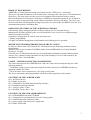
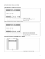
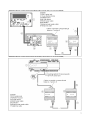
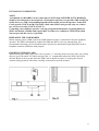
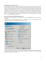
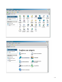
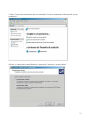
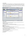
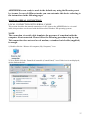
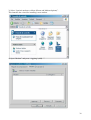
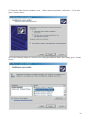
ACCESSORY
Installation and usage
Connection system with serial connection
Connection system with remote connection
Connection system with GSM modem connection
AERWEB30 Connection KIT
AERWEB. 0811. 5154620_00
1
INSTALLATION AND USAGE
Dear customer,
Thank you for buying an AERMEC product. This product was designed based on our
multiannual experience and on special engineering studies; it was built using very
high quality materials and state-of-the-art technologies.
The product quality level is constantly monitored; this is why AERMEC
products mean Safety, Quality and Reliability.
Any information could be modified anytime without prior notice with the
purpose of improving this product.
Thank you again.
AERMEC S.p.A
2
PRODUCT DESCRIPTION
AERWEB is a control and monitoring system based on the “WEB server” technology.
The server can send information to an external client, working in the same way as a normal Internet
Web server. The only need is for the server to be equipped with an Internet browser such as
Microsoft Explorer® o Netscape®. Web pages, including all information attached, are included in
the server; the µc-Linux operating system ensures maximum efficiency and safety. The server can
read, file and check all information coming from any device connected to the RS485 serial line. The
communication protocol is Modbus-Rtu.
OPERATING FEATURES OF THE AERWEB ACCESSORY
• Monitoring, filing, management and recording of alarms for all connected devices.
Management of alarms defined by the user; the possibility to use e-mail, fax or SMS messages
ensures maximum flexibility.
• Interactive management of controls from and for devices
• Tabular programming.
• Graphic and tabular management of information stored during device operation.
MINIMUM SYSTEM REQUIREMENTS FOR THE PC CLIENT
In order to connect from a PC client, the PC client must meet the following minimum system
requirements:
Windows 98® or later, Pentium II 300MHz with at least 64 MB RAM, Java Virtual Machine,
Explorer 5.5 or later.
If needed, the CD- ROM includes the Java Virtual Machine distribution by Sun® Microsystems.
Aermec S.p.a. cannot be held responsible for any kind of damage or loss of data caused by the
installation of Java Virtual Machine.
CLIENT – SERVER CONNECTION POSSIBILITIES
The connection between the AERWEB device and a PC client can be managed using one of the
following methods:
- Via Modem: point-to-point connection using the modem connected to AERWEB and the one
equipped with the PC client;
- Via serial cable: direct connection to a PC using a serial cable.
The above mentioned connecting methods will be described separately in this manual.
CONTENTS OF THE AERWEB 30 KIT
No 1 AerWeb30 device
No 1 RS485 serial cable
No 1 CD-ROM for installing data monitoring software.
No 1 Installation and usage manual
No 1 "Omega" guide, 35 mm
No 1 Shielded, 2-pole cable, 1.5 m
CONTENTS OF THE GSM AERMODEM KIT
No 1 GSM MODEM with mini CD-ROM
No 1 Component for securing the device to the Omega guide
No 1 GSM antenna with connection cable
No 1 power supply cable with power-supply unit
No 1 RS485 serial cable
3
CONTENTS OF THE AERMODEM KIT
No 1 Analog MODEM AERMODEM
No 1 “Omega” guide, 35 mm
No 1 Telephone cable
No 1 RS485 serial cable
No 1 Installation Instruction Sheet
NOTE
For each board connected to AERWEB 30, the board accessory AER485 is needed for GR3
boards and the AER485P2 accessory is needed for pCO2 boards
1. AERWEB30
4. TELEPHONE CABLE
7. GSM ANTENNA
2. AERMODEM
5. GSM AERMODEM
8.AER485
3. RS 485 CABLE
6. AERMODEM
POWER SUPPLY
9. OMEGA GUIDE
10.AER485P2
4
DEVICE INDICATOR LIGHTS
AERWEB 30 DEVICE INDICATOR LIGHTS
AER MODEM DEVICE INDICATOR LIGHTS
GSM AER MODEM DEVICE INDICATOR LIGHTS
5
CONNECTIONS
AERWEB 30 DEVICE CONNECTION WITH GR03 BOARD (SERIAL CONNECTION TO PC)
AERWEB 30 DEVICE CONNECTION WITH PCO2 BOARD (SERIAL CONNECTION TO PC)
6
AERWEB 30 DEVICE CONNECTION WITH GR03 BOARD (CONNECTION VIA ANALOG MODEM)
AERWEB 30 DEVICE CONNECTION WITH PCO2 BOARD (CONNECTION VIA ANALOG MODEM)
7
AERWEB 30 DEVICE CONNECTION WITH GR03 BOARD (CONNECTION VIA GSM MODEM)
AERWEB 30 DEVICE CONNECTION WITH PCO2 BOARD (CONNECCTION VIA GSM MODEM)
8
INSTALLING COMPONENTS
NOTE:
A maximum of 9 BOARDS can be connected to EACH single AERWEB 30. The RS485 line
should reach all boards to be monitored. All telephone operators can provide SMS and DATA
traffic; however, SIM Card enabling depends on the model and on the operator. Some SIM
Cards provide VOICE and DATA traffic, while other SIM Cards provide only one of these
two services at a time (VOICE or DATA).
Contacting your telephone operator, you can get updated information regarding different
SIM Card models available and request DATA traffic to be enabled on a SIM Card which
does not provide this service, if possible.
PREPARING THE GSM MODEM
Before starting, insert a SIM Card in the GSM modem to make a connection with your telephone
operator. The SIM Card should be enabled for SMS and DATA two-way transmission. We
recommend contacting your local mobile phone operator for information regarding SIM Cards or
telephone contracts enabled to such purpose.
INSERTING THE SIM CARD
When inserting the SIM Card, please refer to picture “1” showing the device lower side; use a sharp
object to press the small “B” button and open the “A” compartment where the SIM Card will be
inserted. Remove the tray and insert the SIM Card as shown in picture 2, keeping the electric
contacts facing upwards. After that, carefully reinsert the tray in the modem.
9
INSTALLING THE MODEM ON GUIDES
POSITIONING AND MOUNTING THE AERWEB30/AERMODEM KIT
The AerWeb30 and AerModem devices should be secured using the Omega guide. The Omega
guide should be secured using two self-threading screws on the device electric compartment.
If missing, please make two holes of 3.3 mm on the above mentioned compartment.
If you need to install a GSM AERMODEM, the GSM antenna should be taken outside, in open
field; the antenna is equipped with a magnet on its basis. We recommend positioning the antenna on
the electrical switchboard side and eventually making a hole for the cable.
POSITION FOR MOUNTING THE AER 485/AER485 P2 BOARDS
The AER485 board should be installed in the device electrical compartment and secured using an
“Omega” guide near the AERWEB30 device. The AER485P2 board should be connected inside the
pCO2.
10
AUTOMATIC SERIAL CONNECTION
3.1 AUTOMATIC CONNECTION WITH SERIAL CABLE
This section describes how to automatically connect a PC client to the AERWEB device using a
serial cable; use this procedure with all Microsoft® operating systems, excluding Windows 95 and
NT.
NOTE
The connection with serial cable simulates the presence of a modem inside the computer client
performing the connection. Please follow the following wizard step by step. You do not need a
real modem for this connection; you just need a standard serial cable (supplied).
1) Insert the AERWEB CD-ROM supplied and go to the “Tools/Serial-link” section; select
“SETUP.exe”.
2) The following window will be displayed; press “Successivo (Next)”.
3) Select the serial port where the connection cable will be plugged (please use a standard serial
cable, NOT laplink) and press “Successivo (Next)”.
11
4) Press the following logo again (if Windows testing is displayed); press “Continua (Continue)”.
5) “DISPOSITIVO INSTALLATO (DEVICE INSTALLED)” will be displayed. Press “Successivo
(Next)” again.
6) When "PROCEDURA ESEGUITA CON SUCCESSO (PROCEDURE SUCCESSFULLY
CONCLUDED)" is displayed, press "Fine (Done)".
7) At the end of the automatic connection procedure, the following icon will be displayed on the
desktop. Double click this icon to connect to AERWEB30
Should the automatic connection procedure fail, please connect using a serial connection, as
described on page ?
12
MODEM REMOTE CONNECTION
We recommend using a dedicated telephone line for this type of connection. Please use only the
modem supplied by Aermec. Connect the modem to the serial port located on the back of the device
using the cable supplied with the modem. Connect the modem to the telephone line using the cable
supplied by the manufacturer; please verify if a telephone exchange is installed for accessing the
external line. The connection procedure is divided into two stages. In the first stage a remote access
connection on the PC is created. The second stage corresponds to the procedure which will be
normally used for accessing web pages. Launch the remote access connection which will connect
the PC to the AERWEB30 server through the telephone line; run the Internet Browser and digit
http : // 192.168.0100 on the address bar.
DIAL-UP CONNECTION FOR WINDOWS XP
Following is the set-up procedure to connect the PC client to the AERWEB device using a remote
connection.
1) Please use the “New Connection Wizard” for creating the remote access connection. Open
“Pannello di Controllo (Control Panel)” from the Start menu.
2) If the Control Panel Classic view is displayed, double click “Connessioni di rete (Network
connections)”; if the Control Panel Category view is displayed, click “Rete e connessioni Internet
(Networks and Internet Connections)”.
13
14
3 Click “Creare una connessione alla rete aziendale (Create a connection to the network at your
workplace)”.
4 Select “Connessione remota (Remote Connection)” and press “Avanti (Next)”.
15
5) Click “Avanti (Next)”.
6) Select “Connessione a Internet (Connect to the Internet)” and click “Avanti (Next)”.
16
7) Select “Imposta connessione manualmente (Set up my connection manually)” and click “Avanti
(Next)”.
8) Select “Connessione tramite modem remoto (Connect using a dial-up modem)” and click
“Avanti (Next)”.
17
9) Write “AERWEB 30 DIRECT MODEM” in the “”Nome ISP (ISP Name)” field.
10) Digit the telephone number of the line to which AERWEB is connected. If the number is 9833
and the dialling code is 0437, digit the following number: 04379833. If there is a telephone
exchange and the number to digit for the external line is 0, digit: 0,04379833. After that, press
“Avanti (Next)”.
18
11) Use Aermec as Username and Password. Confirm the password and check the boxes as shown
above.
12) Create a shortcut on the desktop checking the corresponding box.
19
13) Manage the type of connection to be used each time you connect to the Internet. Open Explorer,
“Strumenti (Tools)” menu, “Opzioni Internet (Internet Options)”. Fill in as shown in the window
above. Make sure that the “default” connection is the one suggested by the operating system each
time you connect to the Internet. Anyway, you can always connect manually double clicking the
“AERWEB direct modem” icon in “Risorse di rete (My Network Places)”. At the end of the
connection stage, open the browser and digit 192.168.0.100 in the address bar.
20
SET UP AND ACCESS
Please read the following notes before accessing AERWEB 30.
The user interface is the same for both connections, so there is no difference between the local
connection via serial cable and the remote connection via modem.
Please make sure that Java Virtual Machine is installed in the PC. Run the browser and load the
address 192.168.0.100. As soon as the system is powered, the software loading process starts. The
“Alarm” and “Power” leds blink for a few seconds. When the “Power” led stops blinking, the
system is ready to accept an external connection. After turning on the device for the first time, the
user has to set up AERWEB 30.
ACCESS
When the connection is active, please digit the default IP address in your browser address bar. The
first window displayed asks for User Name and Password. By default, the system allows access
using the following:
- User Name: Aermec
- Password: Aermec
Please consider changing the above mentioned access data, previously checking administrator
privileges.
HOME PAGE
Based on the user privileges, the system can be fully accessed or accessed with some restrictions
(i.e. some sections could not be displayed). The only user who can operate with no restrictions is the
administrator.
21
AERWEB 30 SET UP
Click “Configurazione sistema (System set up)”; the “Configurazione corrente (Current set up)”
window will be displayed, see below (picture 16).
Click “Sistema (System)” to set the system name, description and IP address. The default IP address
is 192.168.0.100. The device is supplied with the English and Italian languages loaded. Please set
the correct Time/Date; these values are very important because AERWEB 30 refers to them
whenever sending an alarm.
22
LIBRARY SECTION FOR AERWEB30
In order for AERWEB30 to work properly, you should install libraries suitable for the type of unit
where AERWEB30 is installed. For example, if a heat pump unit is associated with a library “only
cold”, it will be impossible to find the cycle inversion valve, the fluid probe, etc. Therefore, it is
fundamental to pay careful attention when selecting the file, referring to the rating included. Click
the “hsetup.exe” icon inside the supplied CD-ROM.
The following window will be displayed:
23
If necessary, unlock the Windows protection program. Follow the program step by step until
automatically obtaining the library file to be saved.
Please note that you need to know the machine where the device will be installed.
Example 1:
As for screw compressor machines (PCO2 board), we need to know the circuit where the file will
be saved (master, slave1, slave2)
Example 2:
As for machines with GR3 board, you need to know how many water pumps are installed on the
machine.
24
25
Choose where to save the file in your computer, then save it.
Now you have obtained the file you need (.xwb), which is ready to be installed on AERWEB30
26
INSTALLING LIBRARIES ON AERWEB30
WARNING
DURING THIS STAGE, PLEASE MAKE SURE THAT AERWEB30 IS NOT ACTIVE;
PLEASE REFER TO “LETTURA DATI (DATA READING)” AND "REGISTRAZIONE
DATI (DATA RECORDING)” IN THE FOLLOWING PICTURE.
Open the set up menu using the button on the top left corner of the initial screen and click “Modelli
Dispositivi (Device models)”.
- Click the “Importa (Import)” button.
- Select the library file previously saved and press the “Apri (Open)” button.
27
- The installation program is launched; progress is shown in the progress bars .
At the end, press “Chiudi (Close)”. The file name of the file that you just installed, together with its
identification data (family, parameter map and model) will be displayed in the table.
Exit.
Exit.
- Return to the “Configurazione (Set up)” menu and click “Dispositivi (Devices)”.
- On the top left corner you will see the “Azione (Action)” box. Open it and click “Nuovo (New)”.
28
Enter the machine name, the model name (the file previously loaded) and the address assigned to
the board in the window displayed.
Press the “Add” button.
As for the GR3 board, the address is provided in the set up of the dip-switch with 8 positions on the
display.
As for pCO2 boards, open the "Prog." menu, go to the "Indirizzo seriale per supervisore (Serial
address for supervisor)" screen, digit the desired address (1 to 256) and always set the baud rate to
9600.
If more than one library is installed on the AERWEB 30, please pay careful attention to the address
in order to avoid overlapping.
29
A window with a general recap of all Aerweb30 parameters regarding the unit is displayed. You can
modify the parameter names and the recording times.
(The recording time defines a series of entries; the recording interval which will be associated with
a device corresponds to the above mentioned series of entries.
Example: “Standard = 15 min.”, “Fast = 3 min.”.
You can define up to 5 recording intervals).
Exit.
Now you are ready to monitor the chiller.
-Open the “Dispositivi (Device)” menu from the Home page and click the “Visualizza (Show)”
button.
30
Click “Seleziona un dispositivo (Select a device)”; all the boards that have been set up will be
displayed (you can connect up to 9 devices to AERWEB30). Please select the device to be checked.
AERWEB30 will now connect and all machine operating data will become available.
If you are using AERWEB 30 alone as a data-logger, please modify the serial connection status
with board, activating it (you can do this on the Home page, from the “Lettura dati e registrazione
dati (Data reading and data recording)” section).
You will need to repeat all operations done until now (selecting as well as installing) for each board
to be added to the device.
31
SETTING UP THE MODEM
Click “Modem” and select the modem which is currently in use. If you want to use the GSM
modem together with the option for sending SMS messages, activate the corresponding option.
AERWEB 30 uses the modem for sending e-mails, fax and SMS messages. The modem can also set
up the remote connection.
SETTING UP THE DIAL UP CONNECTION
Click “Dial up” to set the Internet connection for sending e-mails. In order to do this, you need a
valid Internet account. If you don’t have an SMTP server, please leave this field empty. In this case,
AERWEB 30 will try to send the e-mail directly to the recipient. Not all ISPs (Internet Service
Providers) support this sending option. For this reason, we recommend using an SMTP server, if
possible.
PERMANENT LOCAL CONNECTION
AERWEB 30 can also be used as a permanent local connection via serial cable. With this operating
mode, whenever an alarm is generated, the local connection will be automatically deactivated and
priority will be given to the modem. Local access will be disabled during the whole period in which
the modem sends alarms. Depending on the operating system used, you can set connection options
for automatic reconnection. After having set the local connection again, you will not need to input
User Name and Password again. However, if, during a local working session, AERWEB 30
receives a remote connection request, priority is given to the modem again and the local connection
is interrupted . After this interruption, User Name and Password will have to be input again. If you
don’t log in again, an error message will be displayed (see below).
32
SETTING UP AUTOMATIC REDIALLING
Please refer to the following procedure for setting up automatic connection in Windows XP:
1) Right click the “Risorse di rete (My Network Places)” icon and select "Proprietà (Properties)".
2) Right click the AERWEB 30 Serial Cable icon and select “Proprietà (Properties)”. After that,
select the “Opzioni (Options)” tab.
3) Set parameters as needed in the “Proprietà (Properties)” window:
- “Numero tentativi (Redial attempts):”.
- “Intervallo prima di ricomporre (Time between redial attempts):”.
- “Tempo di inattività prima della disconnessione (Idle time before hanging up):”.
- “Ricomponi se cade la linea (Redial if line is dropped)”.
33
CATEGORIES
This function can be used for managing devices, associating options and features specified in the
“Categorie (Categories)” database. After that, in the “Configurazione Dispositivi (Device set up)"
stage, each device can be associated with a specific entry chosen from specific device categories.
For many categories, an entry can be set as the "Default" entry, so that such entry is automatically
used for each device when associated.
TYPOLOGIES
This software identifies some categories related to typologies of the client where the device is
installed; up to 5 categories can be specified.
To input a new entry:
1) Go to the "Nome (Name)" field and input the desired entry.
2) For setting this entry as the default entry when associating a category to the devices, check the
"Default" box.
To modify an existing entry:
1) Select the entry to be modified from the “Selezione (Selection)” list;
2) Modify the entry in the “Nome (Name)” field;
For modifying this entry and making it the default entry when associating a category to the devices,
check the "Default" box and press “Modifica (Modify)”.
To delete an entry from the list:
1) Select the entry to be deleted from the “Selezione (Selection)” list;
2) Press “Cancella (Delete)”;
3) Confirm on the deletion confirmation box.
To reset the list:
Press “New”;
34
To delete all entries
1) Press “Cancella All (Delete All)”;
2) Confirm on the deletion confirmation box.
ALARMS
Setting alarms is one of the most important stages of the setting up procedure. The user has to create
a recipient phonebook and specify the corresponding alarm typologies.
RECIPIENT PHONEBOOK
Here you can specify if the alarm message should be sent to a mobile phone, to a fax or to a
computer. This system allows receiving an SMS message on a mobile phone, a fax or an email
regarding the alarm generated by the machine.
The “Rubrica Destinatari (Recipient Phonebook)” contains all recipients enabled to receive alarms.
Up to 5 recipients can be specified.
AERWEB 30 can transfer alarms via SMS message, e-mail and fax.
AERMODEM can send fax and e-mails.
AERMODEM GSM can only send SMS messages.
To input a new entry
1) Go to the "Nome (Name)" field and input the desired entry.
2) Press “Inserire (Input)”.
To modify settings
1) Choose the user whose settings you want to modify.
2) Digit the new values or status in the appropriate fields.
3) Press “Modifica (Modify)”.
To delete a user
1) Choose the user to be deleted.
2) Press ”Cancella (Delete)”.
To delete all users from the list
1) Press “Cancella (Delete)”.
To reset all entries
1) Press “New”.
NOTE
Each user can be associated to a calendar, if needed.
35
ALARM TYPOLOGIES
The alarm typologies are a list of entries chosen by the user that can be associated with different
cases of alarm; they allow to group together alarms with similar features. Alarm typologies can be
useful to group alarms such as: Temperature, Pressure, No-Link, etc. Difference among typologies
can be further specified adding details such as: High Temperature, Low Temperature, High
Pressure, Low Pressure, etc. The user can also customize the accuracy for different cases of alarm.
Up to 5 different alarm typologies can be specified. Based on the effective setting chosen by the
user, alarms can be sent immediately or after a specific accumulation time. “Ritardo (Delay)” is
used to avoid sending a large number of messages. If an alarm lasts less than the value specified for
“Ritardo (Delay)”, such alarm will only be registered in the system History but it will not be sent to
the recipient. After the "Accumulo (Accumulation)" interval has lapsed, the alarm is sent.
To input a new alarm typology:
1) Click “Nome (Name)” and input the relevant text.
2) Set the “Ritardo (Delay) and “Accumulo (Accumulation)” values.
3) Input the text for the e-mail, SMS message and/or fax.
4) Check the name of the corresponding “Destinatario (Recipient)”. If necessary, set the default
value.
To modify an existing alarm typology:
1) Select the corresponding entry in the “Selezione (Selection)” box.
2) Modify the desired fields.
3) Press the “Modifica (Modify)” button.
To delete an existing alarm typology:
1) Select the corresponding entry in the “Selezione (Selection)” box.
2) Press the “Cancella (Delete)” button.
To delete all entries from the list
1) Press “Cancella (Delete)”.
To reset all entries:
Press “New”.
To activate the “Open Collector” output:
1) Check the corresponding field. When an alarm is active, the Open collector will switch its status.
WARNING
The Open Collector needs external power, 12V DC on PIN 5 (please refer to the sticker). The
maximum output current is 50mA.
START RECORDING
Now the general set up is complete and you can activate the data reading/recording options for data
coming from the RS485 serial line. Click “Modifica (Modify)”.
Select/deselect the desired options and press “Applica (Apply)”:
Data reading:
Data recording:
Alarm TX:
AERWEB 30 only reads data from the RS 485 line
AERWEB 30 records data from the RS 485 line
AERWEB 30 sends alarms from the RS 485 line
36
AERWEB30 is now ready to work in the default way using the libraries preset
by Aermec. In case of different needs, you can customize this device referring to
the instructions in the following pages.
MANUAL SERIAL CONNECTION
LOCAL CONNECTION WITH SERIAL CABLE.
This section describes the manual connection of a PC client to the AERWEB device via serial
cable; this procedure can be used with the Microsoft® Windows XP operating systems.
NOTE
The connection via serial cable simulates the presence of a modem inside the
computer client connected. Please follow the following procedure step by step.
This connection does not need a real modem; a standard serial cable (supplied)
is enough.
1) Double click the “Risorse del computer (My Computer)” icon.
2) Now double click the “Pannello di controllo (Control Panel)” icon. If this icon is not displayed,
use the link on the left.
37
3) Select “Opzioni modem e telefono (Phone and Modem Options)”.
This launches the wizard for installing a new modem.
4) Open “Modem” and press “Aggiungi (Add)...”.
38
5) Check the “Non rilevare il modem: verrà… (Don’t detect my modem: I will select....)" box and
press "Avanti (Next)".
6) Use the following image as a reference for setting the different fields; after setting, press "Avanti
(Next)".
39
7) Select the serial port where the cable will be connected and press “Avanti (Next)”.
8) Press “Fine (Done)” to conclude the modem installation wizard.
40
9) Select the modem you just installed as shown in the picture below and press "Proprietà
(Properties)".
10) Check that 57600 is set for “Velocità massima (Maximum speed)”. In several cases we
observed anomalies in the operating system, which automatically resets an incorrect value after the
parameter has been set correctly.
41
11) Press OK until all windows are closed. Look for the “Risorse di rete (My Network Places)” icon
on the desktop and right click it, then select "Proprietà (Properties)".
12) Click “Crea una nuova connessione (Create a new connection)”. This will launch an automatic
wizard for creating a dial-up connection.
13) This will launch an automatic wizard for creating a dial-up connection. Press “Avanti (Next)”.
42
14) Select “Connessione a Internet (Connect to the Internet)” and press “Avanti (Next)”.
43
15) Select “Imposta connessione manualmente (Set up my connection manually)” and press “Avanti
(Next)”.
.
16) Select “Connessione tramite modem remoto (Connect using a dial-up modem)” and press
“Avanti (Next)”.
44
17) Digit “AERWEB30 cavo seriale (AERWEB30 serial cable)” in the “Nome ISP (ISP Name)”
screen. Press “Avanti (Next)”.
18) Digit 123 in the “Numero di telefono (Phone Number to Dial)” screen. The phone number is a
dummy number, since the modem and the phone line are only simulated. Press “Avanti (Next)”.
45
19) Digit Aermec as User Name and Password.
Check the boxes as shown in the picture below. Press “Avanti (Next)”.
20) The procedure is now complete. Check the “Aggiungi collegamento… (Add a shortcut to this
connection...)" box and press "Fine (Done)".
46
21) The following window is displayed on the desktop. DO NOT PRESS “COMPONI (DIAL)”,
press “Proprietà (Properties)”.
22) Press “Configura (Configure)” and make sure that the values correspond to the ones shown in
the picture below.
Press “OK”.
47
48
23) Open the “Opzioni (Options)” tab and set the fields as shown in the picture below:
Press “OK” and go back to the connection window.
When you want to connect to AERWEB30, launch the connection you just created.
Wait until the procedure is successfully completed and digit the default IP address 192.168.0.100 in
the address bar.
You can also use the icon on the desktop:
49
CALENDAR FUNCTION
The Calendar function is used for setting specific activity or inactivity intervals for a specific
resource or event. You can create customized calendars for people as well as for specific system
functions. The resources associated with a calendar will be made available only on the days and in
the time periods marked as “Enabled”; as for the “Not Enabled” days, the resource will never be
activated or called. When the system has to activate a resource which is associated with a calendar,
it will check first that such resource is available, which means that the time in which the system
wants to call is included in the profile preset as Enabled. If the resource is enabled, the system will
call it, otherwise not. This applies, for example, for calls to a Help Centre associated to a specific
calendar and for calls to the “Lights on” function, which will be associated with a different
calendar. You can create as many calendars as you need. Each calendar can be associated with one
or more resources. Each calendars works on a sheet, on a weekly basis for each month; each “Day”
box is associated to a specific colour, based on the setting of that day.
Days can be set as follows:
• Enabled days - green box;
• Partly-enabled days – yellow box;
• Not Enabled days – grey box.
On the “Not enabled” days, the resource will not be made available for 24 hours. As for “Enabled”
and “Partly enabled” days, you can set the times in which the resource will be available.
50
Setting a typical repetitive week
(Example: setting Saturday and Sunday as always disabled and Wednesday partly enabled).
1) Select a random month.
2) Point the mouse on the “Saturday” pink box on the first top row.
3) Left click with the mouse and choose "Imposta a non abilitato settimanale (Set As Weekly Not
Enabled)".
Do the same operation for “Sunday”.
Do the same operation for “Wednesday” but choose “Set As Weekly Partly Enabled”. The
correspondent boxes become grey and yellow respectively, for all months and all years.
51
Setting the enabling interval for enabled and partly enabled days
(Example: specify the enabling interval 08:00 to 20:00 for enabled days and 08:00 to 13:00 for
partly enabled days).
1) On the top right box, “Individual Day Time Band”, set the “From” box at 08:00 and the “To” box
at 20:00.
2) Press the “Set for All Enabled” button.
This sets the above mentioned enabling interval for all working days. Repeat the same operations
for partly enabled days and at the end press the “Set for All Partly Enabled” button.
Viewing daily options
In order to view the options set for every single day, point the mouse on the corresponding box and
right click.
52
Setting/modifying each single day
You can change settings for each single day at any time:
1) Point the mouse on the desired day box;
2) Left click and choose the desired setting:
Set As Enabled: sets only this day as Enabled.
Set As Not Enabled: sets only this day as Not enabled.
Set As Yearly Not Enabled: sets this day as always Not Enabled for all years.
Set As Partly Enabled: sets only this day as Partly Enabled.
Set As Yearly Partly Enabled: sets this day as always Partly Enabled for all years.
Setting a series of days
You can select a series of following days and set the same option.
For example, you can specify a holiday period for any month during the year:
1) Point the mouse on the first day of the period and, left clicking with the mouse, scroll until the
last day of the period, then release the button.
2) Choose the option for the selected period. All boxes of this period will be coloured accordingly.
Managing the Calendar
The buttons for managing the calendar are the ones in the corresponding box (picture 72) in the
bottom right corner.
53
Open New: opens a new calendar. By default, all Saturdays and Sundays are set as holidays.
Save Actual: saves the currently displayed calendar, including any changes made.
Delete Actual: deletes the calendar displayed from the system calendar list.
Save As: allows you to save the calendar displayed with a name chosen by the User.
54
VIEWING AND MANAGING DEVICES
SETTING UP DEVICES
In the Device Set up stage, you can associate specific options and functions to each device installed
in the System. Please make sure that all controllers connected to the RS485 line have been detected.
As for the selected device, AERWEB 30 will display only such options (categories, alarms, inputs,
etc.) associated to that specific device. Moreover, this window allows you to associate the
previously created device categories and Alarm Typologies to a device. The options to be assigned
to analog and digital inputs are made available in this windows as well. If a category entry is not
available or if you want to assign a new one to a specific device, the corresponding window can be
re-opened and the new input can be made.
FIRST DEVICE SETTINGS
Click “Nome (Name)” and modify the corresponding values as needed. Assign the reading speed
selecting an entry from the “Intervallo (Interval)” menu. Decide if this device shall be used only for
reading data (check the “Lettura Dati (Data reading)” box) or also for recording data (check the
“Registrazione Dati (Data Recording)” box).
“Data Buffer” is a very useful function when an alarm is generated: the system records data
transmitted from the RS485 line at the maximum speed available for 10 minutes before and 5
minutes after the alarm. This means that, even if the “Interval” value is set to 5 minutes and the
average serial line inquiry time is set to around ten seconds, AERWEB 30 will store data for 15
minutes (before and after the alarm) with a much higher frequency, using more storage space in the
system. In order to save the changes made so far, press the “Modifica (Modify)” button.
55
ASSIGNING CATEGORIES TO DEVICES
After having selected a device, you can associate previously created categories to it. For example, in
the previous paragraph the device was associated with the correct value for “Intervallo (Interval)”.
In the set up page there are 3 menus for assigning a category to a device: "Intervallo (Interval)",
"Tipologia (Typology)" and "Tipologia (Typology)" for the alarm section. The user should now
find all information needed in these menus. If this is not the case, please go back to the
corresponding page and input any missing entry.
ASSIGNING ALARM TYPOLOGIES
If you haven’t done it already, select the desired device from the list. Only alarms that can be
generated from the source device selected are automatically displayed in the corresponding
windows. Each alarm can be associated with a tag, which will be displayed together with the alarm
name on all screens. Select the desired Alarm Typology, so that all actions of the alarm associated
with the Alarm Typology assigned correspond to the alarm. If there is no Alarm Typology suitable
for the selected alarm, go back to the “Allarmi (Alarms)” window and create a new Alarm
Typology with the features you need.
ORIGINE (SOURCE): based on the device model, you can manage different alarms; if the desired
alarm is not displayed, this means that such alarm is not available for that specific device.
NOME (NAME): each alarm can be associated with a customized user caption. The system will
display this caption whenever the alarm is generated.
TIPOLOGIA (TYPOLOGY): link to the corresponding “Tipologie Allarmi (Alarm Typologies)”.
VIS. (SH) (visualizza - show): if enabled, it displays the relevant quantity.
REG. (REC) (registra - record): if enabled, alarms are recorded.
56
SETTING DIGITAL INPUTS, OUTPUTS AND DEVICE STATUS
The central section can be used to customize analog and digital inputs and the device operating
status.
NOME (NAME): when displayed for the first time, each device is associated with the standard
values stored in the AWEB 30 database. Users can rename captions simply clicking on them and
assigning them the name they find more appropriate. Please pay careful attention to the difference
between whole and decimal values. Decimal resolution is the factory setting for all devices; if you
modify this value and set the whole resolution, please make sure to make the same change in
AERWEB 30. All captions use decimal values.
VIEWING A DEVICE
1) Click “Dispositivi (Devices)” -> “Visualizza (View)” to choose the controller to be displayed.
AERWEB 30 will show all the device quantities.
57
Selecting a device
Use the “Filtro Dispositivi (Device Filter)” menu. The page with data regarding the selected device
is displayed. The first top section is divided into bands referring to typical device quantities. This is
a “static” page, since the values shown are the ones recorded when the page is open. You can
update such data checking the "Auto" box; in this way, the page will be updated using the value set
in the box next to it. You can also press the "Aggiorna (Update)" button any time.
Controls
The selected device controls are shown in the bottom section of the page; these controls can be
selected and activated on the device itself. The page boxes update automatically showing the new
device status.
PARAMETERS
The “Parametri (Parameters)” function is used to manage parameters associated with device
operation. From the “Home Page”, select “Parametri (Parameters)” from the “Dispositivi
(Devices)” menu. Click “Carica dispositivo (Load device)”.
58
Carica da Dispositivo (Upload from a Device): • uploads parameters from a device;
Carica da file (Upload from a file): uploads parameters from a file saved in the user PC hard disc;
Scrivi su Dispositivo (Write on Device): • writes new parameters on the device;
Scrivi su Dispositivi (Write on Devices): • writes new parameters on compatible devices;
Salva su File (Save as File): saves parameters in a file in the user PC hard disc;
Stampa (Print): prints the parameter list.
Use the following criteria to filter parameters:
Tipologie (Typologies): to filter by category (“All” includes all devices);
Dispositivo (Device): to select the desired device;
Gruppo (Group): to load only a specific parameter group;
Menu tutti (All menu): • to upload a specific programming level (Pr1, Pr2, All)
Press the “Read” button to load the parameter page. Loading time depends on the number of
parameters and the connection speed.
The parameter window includes the following columns:
Etichetta (Tag): parameter description;
Descrizione (Description): parameter function description;
Attuale (Current): current parameter value;
Nuovo (New): new value which can be set by the user;
Min /Max: parameter interval allowed;
59
Min /Max: parameter interval allowed;
UM: unit of measurement;
Pr: parameter programming level;
Salva (Save): to select the parameter to save.
Modifying a parameter
Input the desired value in the “New” column. Based on the type of parameter, you can select the
value from a scroll-down menu. Confirm the new value clicking outside the “New” area. You
cannot input a value above the standard parameter limits; doing this, an error message is displayed
and the value is highlighted in red. You can modify more than one parameter at once.
Modifying the programming level
Modify this value in the “Pr” column.
Saving new parameters for a device
1) Select “Write on Device” from the “Action” menu;
2) Confirm the operation pressing “OK”.
Saving parameters
Parameters can be saved on the user PC hard disc and they can be used on other devices.
1) Open an active parameter window, press the ”Action” menu and select “Save on File”.
2) Check the fields you want to save on the ”Save” column.
3) Press “Save” on the top left corner.
4) Press “Save All” to save all parameters.
The procedure to follow is the one normally used to save a file in Windows.
ALARM MENU
ALARM HISTORY
This function can be used to view the alarm history stored in AERWEB30.
Viewing and searching alarms
On the Home Page, select “Allarmi (Alarms)” and then “Archivio (Library)”.
This page is divided into 3 main sections.
“Filtro Dispositivi (Device Filter)” defines the group and device to search.
“Filtro allarmi (Alarm Filter)” defines the alarm typology to search.
“Azione (Action)” menu can be used to choose an action:
Saving in the hard disc in HTML format, displaying in the current window or printing alarms.
AERWEB 30 automatically loads all alarms and the user can use filters.
Values for the “Fine (End)” column:
Attivo (Active): alarm still active
Auto: alarm automatically stopped and not active anymore.
Stop Lett. (Stop reading): monitoring stopped by a user.
Riavv. Sist. (Restart sys.): system restarting
60
Device status from the alarm history page
If you want more detailed information regarding the device that generated an alarm, click on the
device name; the “Visualizza (View)” window will be displayed, showing all values recorded when
the alarm was generated. For an overview of the current system status, load the "Visualizza (View)"
window using the menu on the Home Page.
Printing the alarm list
Select “Stampa (Print)” from the “Azione (Action)” menu.
The file is printed from the user PC using any printer connected to the PC. Follow the Windows
printing procedure.
MANAGING ACCESS AUTHORIZATION TO AERWEB 30
Select “Configurazione (Set up)” from the Home Page, then select "Permessi (Authorizations)".
This is one of the most important sections in order to ensure that AERWEB 30 works correctly.
You can create up to 3 users and grant or deny them the possibility to interact with the monitoring
system.
We recommend creating a user authorized to only read system data and another user authorized to
modify the system as well. A third user, the administrator, should be the only user enabled to
interact with fundamental system sections such as managing alarms and devices, etc.
When powered on for the first time, AERWEB 30 is set up to accept an administrator user and two
standard users. If you want to change these settings, click the “Nome Utente (User Name)” and
“Password” fields and change them as needed.
61
Press “Applica (Apply)”.
In order to authorize or deny access to specific system areas, check or uncheck the corresponding
fields on the “Permessi (Authorizations)” window. Press “Applica (Apply)”.
MANAGING USERS
You can interact with a user in 3 different ways:
Granting/denying access privileges.
Disabling a user (“Enabling” control box).
Changing User Name and Password.
TOOLS SECTION
AERWEB 30 is equipped with a complete set of programs to help the user with server maintenance
and when searching potential connection problems on the RS 485 line.
LIBRARY STATUS
You can use this window to obtain important information on how long libraries are stored in the
system internal memory. The method used is the FIFO code (first stored data is deleted first); this
means that, when the available memory is full, older data is dynamically overwritten by newer data.
In order to change the library storage period, you can modify quantities or storage speed. The bigger
the quantity, the quicker will be the data acquisition interval and the shorter will be the library
duration. Please note that the system does not stop working when the memory is full, since older
data is overwritten. Users can download data any time using the “Data/Grafici (Data/Graphs)”
menu.
62
Value
Meaning
Library
First data
System memory used
First data available
Last data
Last data available
Estimated Library duration
How many days after storing the
last data can be managed by the
Library.
Minimum time required by the
system to search all devices
connected to the RS 485 line.
Alarm buffer size.
Minimum recording
interval
Buffer duration
Unit of
measureme
nt
Percentage
Date and
time
Date and
time
Date and
time
Minutes/sec
onds
Minutes/sec
onds
RS 485 TEST
You can carry out a diagnostic test on the RS 485 serial connection to check its status.
Select “RS 485”; the following window will be displayed.
Clicking “Test”, AERWEB 30 briefly checks the RS485 line exchanging data packets with the
device analyzed. If the test is positive, the following results will be displayed:
63
EVENTS LIBRARY
In this window you can check events and activities for each user authorized to access AERWEB 30.
The library is in FIFO format and it shows activities carried out by each user in a hierarchic way.
Pressing “Cancella (Delete)” the library is emptied and pressing “Aggiorna (Update)” the library is
updated in real time.
SERVER STATUS
Select “Stato Server (Server Status)”. This window displays any error message from AERWEB 30.
You can access this section in a quick way from the Home Page as well.
If there is a small red warning sign icon next to “Stato Server (Server Status)”, just click on it to
access the corresponding section.
64
MESSAGES STATUS
In this section you can check the alarm message sending status.
If any message has not been sent correctly, here you will find the reason and the current status of
the unsent message. The system automatically tries to send the message again, should the first
sending fail.
INFORMATION MENU
SYSTEM VERSION
On the Information menu, click “About”:
The example below shows that the system version is version 2.0
UPDATING THE SYSTEM
An important feature of AERWEB 30 is the possibility to update it via modem or serial cable. This
procedure can be activated by the administrator only.
From the Home Page, select the “Informazioni (Information)” menu, then select “System Update”.
In order to carry out the update, Java Virtual Machine should be installed in the PC used.
During the update procedure, which could require a few minutes, the system stops the RS 485
monitoring process.
65
GRAPHS
GRAPHS WITH AERWEB 30
Access this section from the “Data” -> “Grafici” (“Data” -> “Graphs”) menu.
Based on the value set for “Intervallo (Interval)”, the system stores values from RS 485. Please note
that these “graphic libraries” will increase in size, slowly using more and more system memory.
VIEWING GRAPHS
Select “Grafici (Graphs)” from the “Data” menu.
Select the desired device using the “Filtro dispositivi (Device Filter)” list and selecting the specific
device from the list.
The window will automatically update showing typical quantities for the device selected. The first
field displayed is “Intervallo disponibile (Available Interval)”, showing the whole history library
available; the second field is “Intervallo selezionato (Selected Interval)”, that can be used to select
only a specific interval to be displayed on the graph.
The bigger the interval to be displayed, the more the time required to create the graph. For a first
brief analysis, please select an interval for the period needed.
In this way you can view samples in an accurate way.
If needed, you can use the “Densità Grafico (Graph Density)” parameter to reduce samples used
when creating the graph. In this way you can reduce the time needed for creating the graph (useful
when connecting via modem), although the accuracy will be reduced as well.
There are 3 areas available to manage quantities to be displayed:
– Analog (analog probe inputs)
– Device Status (status of the device)
– Device Output (outputs of the device).
The system can manage up to 3 analog quantities (AG1 – AG2 – AG3) and two digital quantities
(DG1 – DG2).
You can choose the colour of the line for each value to be displayed in the graph; moreover, several
compatible quantities can be displayed in the same graph or separated.
Use the scroll-down menu to choose one of the following values: AG1, AG2, AG3, DG1 e DG2.
The maximum number of graphs is 5; there are no limitations to the number of quantities that can
be displayed on the graph.
In order to choose the graph accuracy, use the “Densità Grafico (Graph Density)” parameter; a
higher density corresponds to a longer download time.
Pressing the “View” button, the graph displaying procedure starts.
The graphic part is based on a Java Applet, which needs Java Virtual Machine correctly installed on
the user PC to work properly.
Based on the software version, a message will be displayed to confirm that the user accepts the
software usage terms.
Aermec S.p.a. ensures that the software is free from viruses; carry on pressing OK.
While downloading data, you can check the progress in the following window. At the end, the
graph will be displayed.
66
Zoom in/out
Before zooming, select the graph you want to zoom (if more than one graph is displayed).
Left click on the graph bar. To zoom in, keep the mouse left button pressed. To zoom out, keep the
mouse right button pressed.
67
Zooming one area
Make sure you selected the desired graph clicking on the header bar.
Point the mouse on the graph and, keeping the mouse left button pressed, circle the desired area
with a rectangle. If the size of the area selected is not appropriate, click with the mouse outside the
area and repeat the operation.
Left click inside the selected rectangle to activate the zoom.
Resetting the original scale
Select “Reset Size” from the “Scale” menu.
68
Manual scale
Axis are automatically scaled so as to represent the whole selected time interval and the minimum
and maximum values for the quantity selected. In order to customize the scale, choose ”Manual
Size” from the “Scale” menu.
You can set the X and Y values in the window that will be displayed.
Synchronizing graphs
When information related to one device is displayed in two graphs, axis are automatically
synchronized. If the user zooms in, the system adapts the scale to the new size, loosing its
uniformity with other graphs.
To use a single scale for all graphs displayed, check “Sync” in the “Tools” menu. Repeat this
operation for all graphs you intend to keep synchronized.
Each time you zoom, the graphs will be synchronized with one another.
Legend
The graph legend is automatically displayed at the top left corner.
If the legend is covering an important area, you can move it or close it as you would do with a
standard Windows box. To activate the Legend again, select it from the “Tools” menu.
69
Saving a graph
Use this function to save the current graph on the user PC hard disc. Select “Save” from the “Tools”
menu.
Please use the standard procedure used for saving a file in Windows.
On the bottom left corner of the window there is a dialog box where you can choose the format for
saving the file: test (TXT) or Web page (HTML).
Loading a saved graph
Use this function to load a graph previously saved on the user PC hard disc. Select “Load” from the
“Tools” menu.
This is the standard procedure used for loading a file in Windows.
Printing a graph
Use this function to print a graph on the user PC local printer.
Select “Print” from the “Tools” menu.
This is the standard procedure used for printing a file in Windows.
Deleting the graph library
Select “Canc. Arch. Dati (Delete Data Library)” from the “Azione (Action)” menu.
Warning: deleting data from the library frees up system memory; however, this operation is nonreversible.
Background colours
The graph background colours depend on the system status.
White indicates normal operation.
Green indicates that the device is Off.
Grey indicates that the device is in No-link status
Pink indicates that data capture is stopped.
Select “Help” from the ”Help” menu.
EXPORTING DATA
As mentioned in the previous paragraph, you can export data from AERWEB 30 to a PC.
You can export data in text format (TXT) as well as Web page format (HTML). Select “Salva su
disco (Save to disc)” and refer to the picture for operating details.
70
Example of data saved in text format:
DELETING DATA
To delete all data stored, open the “Dati” -> “Grafici” (Data” -> “Graphs)” menu. Select “Canc.
archivio dati (Delete data library)” from the “Azione (Action)”menu.
Please be careful, since this operation will delete all data stored in the devices and is non reversible.
VIEWING GRAPHS FROM PC
You can view graphs even if you are not connected to an AERWEB30 system. Before doing this
you need to save a graph on your PC.
If you are trying to display a graph on a local PC for the first time, you need to install a software
included in the CD-ROM supplied with the device.
Insert the CD-ROM and press “Graph viewer” in the “Programmi accessori (Accessory programs)”
section.
Confirm the software installation path pressing “Start”.
71
At the end of the procedure, the following window will be displayed:
Now you will be able to run the program from the PC “Start” menu, through “AERWEB30 graphs
viewer”:
Based on the PC security settings (the following example refers to Windows XP Service Pack 2),
you might need to authorize the software running operation.
72
Right click the header bar and authorize the software running operation. Answer “Sì” (Yes) to the
following question.
At the end, the following window is displayed:
73
Press “Open a graph”, confirm that Java Virtual Machine is running and search the graph previously
saved on your PC.
74
Use the Windows standard window to load the above mentioned file:
75